

Page 1
Quick Installation Guide
1 3
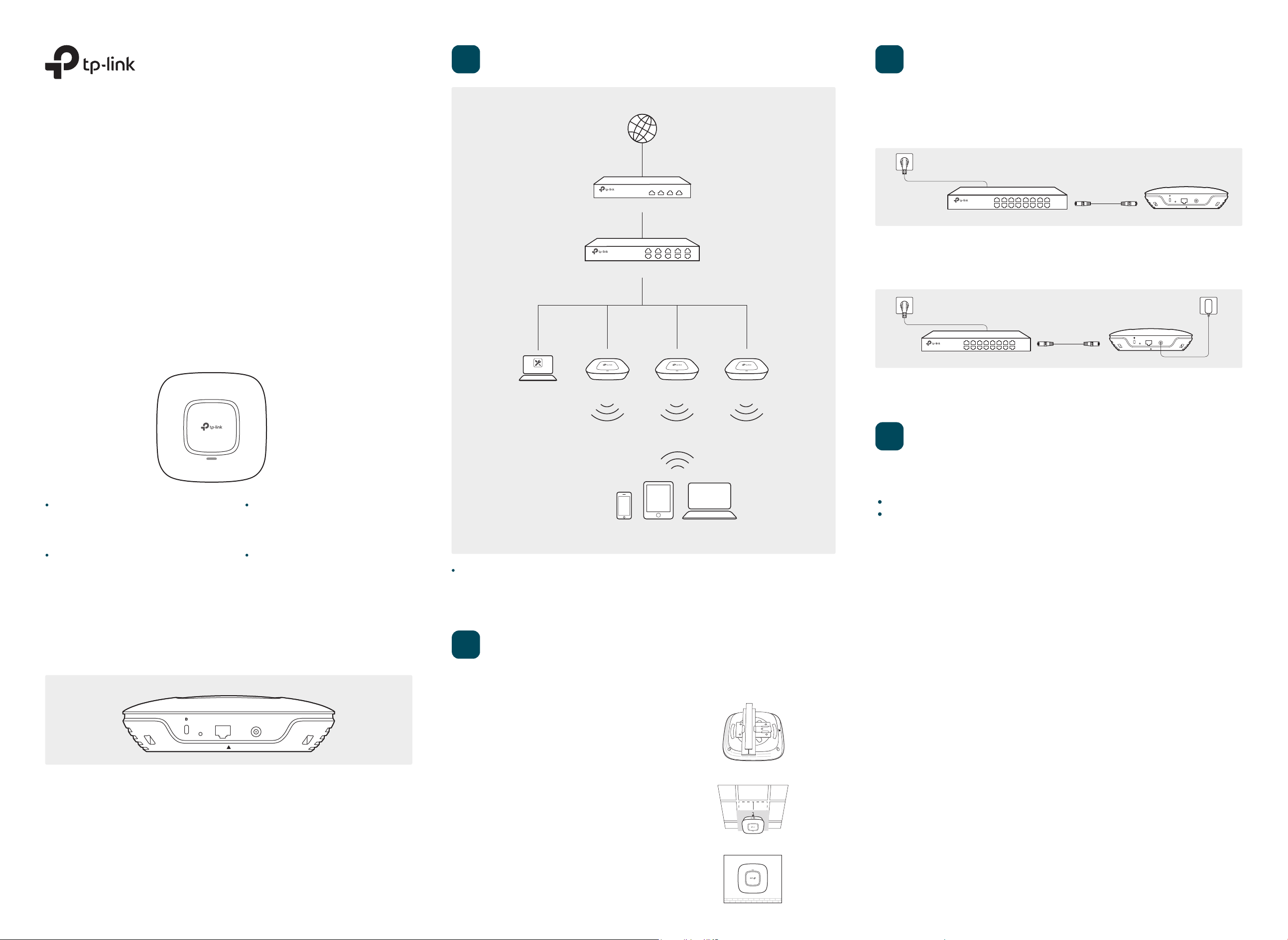
Typical Network Topology
The EAP can be powered via a PSE device (such as a PoE switch) or a power adapter.
Internet
Via PoE Switch
Connect an Ethernet cable from the PoE switch to the ETHERNET port.
Power Supply
AC1750 Wireless Dual Band Gigabit Access Point
EAP245
LED Indication
EAP Controller
PC
Router
Switch
PoE Switch
RESET ETHERNET
POWER
Via Power Adapter
Plug one end of the provided power adapter into the POWER port of the EAP and the other
end to a standard electrical wall outlet.
RESET ETHERNET
PoE Adapter
POWER
Switch
EAPEAPEAP
4
Software Configurations
Solid green
The device is working properly.
Flashing red
System errors. RAM, Flash,
Ethernet, WLAN or firmware may
be malfunctioning.
Interface Panel
RESET ETHERNET POWER
Flashing yellow
Firmware update is in progress. Do not
disconnect or power o the device.
Double-flashing red, green, yellow
The device is being reset to its
factory default settings.
Clients
A DHCP server (typically a router) with DHCP function enabled is required to assign IP addresses to the EAPs and
clients in your local network.
2
The EAP can be ceiling rail mounted, ceiling-mounted, or wall-mounted.
The instructions for various mounting options are on the back of this Quick Installation Guide.
Hardware Installation
Option 1: Ceiling Rail Mounting
The EAP supports two configuring options:
To configure and manage mass EAPs via centralized controller software, please refer to Option 1.
To configure a single EAP via a web browser directly, please refer to Option 2.
Option 1: Via EAP Controller
Step 1: Installing EAP Controller
On the PC, download the EAP Controller installation file from http://www.tp-link.com/en/download/EAP-Controller.html.
Run the file and follow the wizard to install the EAP Controller.
Step 2: Configuring EAP Controller
Launch the EAP Controller and follow the step-by-step instructions to complete the Quick Setup. After the wizard is
finished, a login screen will appear.
Step 3: Logging in to EAP Controller
Enter the admin name and password you created and click Sign In. Then you can further configure the EAP Controller.
For More Congurations
You can now manage your wireless network and view network statistics using the EAP Controller. Please refer to the
EAP Controller User Guide for more information about conguring and using EAP Controller.
Option 2: Via Web Browser
RESET
With the device powered on, press and hold the button for about 8 seconds until the LED
flashes red, then release the button. The device will restore to factory default settings.
ETHERNET
The port is used to connect to a router or a switch to transmit data or to a PSE (Power
Sourcing Equipment), such as a PoE switch, for both data transmission and Power over
Ethernet (PoE) through Ethernet cabling.
Option 2: Ceiling Mounting
Option 3: Wall Mounting
Step 1: Connecting to the EAP Device
Power on the EAP and connect wirelessly by using the default SSID (format: TP-LINK_2.4GHz/5GHz_XXXXXX).
Step 2: Logging in to the EAP Device
Launch a web browser and enter http://tplinkeap.net in the address bar. Use admin for both Username and Password to
log in.
Step 3: Configuring the EAP Device
Set up a new Username and Password for secure management purpose. Modify the wireless parameters and reconnect
your wireless devices to the new wireless network.
Page 2
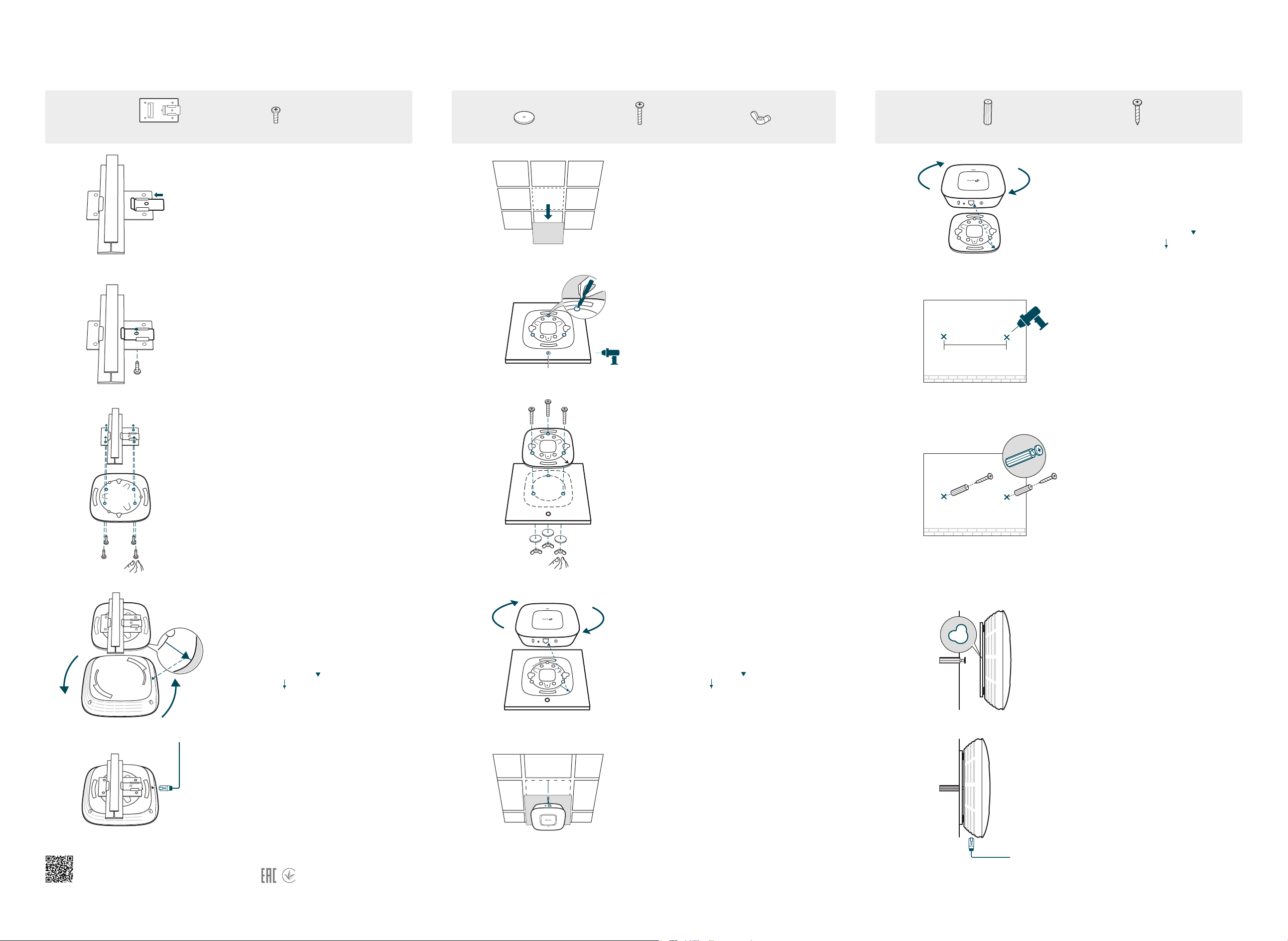
Option 1: Ceiling Rail Mounting
Option 2: Ceiling Mounting
Option 3: Wall Mounting
Note: We recommend that you install the EAP with the Ethernet port downward.
Ceiling T-rail Clip
M3×6 Pan-head Screws(Qty.5)
1
Position the Ceiling T-rail Clip and push
the movable part toward the rail base.
2
Use an M3×6 pan-head screw to secure
the T-rail Clip onto the ceiling rail.
Hole for Ethernet cable
X3
Wing Nuts (Qty.3)Washers(Qty.3) M3×30 Pan-head Screws (Qty.3)
1
Remove the ceiling tile.
2
Place the mounting bracket in the center
of the ceiling tile. Mark three positions for
the screw holes and a position for the
Ethernet cable hole.
Drill three 4mm holes for the screws and a
25mm hole for the Ethernet cable at the
marked positions.
M3×28 Plastic Wall Anchors(Qty.3)
98.6mm
M3×20 Self-tapping Screws (Qty.3)
1
Attach the EAP to the mounting bracket
by aligning the arrow mark on the EAP
with the arrow mark on the mounting
bracket, then rotate the EAP until it
locks into place, as shown on the left.
2
Make two small pencil marks on the
wall. Make sure the two marks are level
and 98.6mm apart.
Drill a 6mm hole through the center of
each mark.
3
Attach the mounting bracket to the
Ceiling T-rail Clip using four M3x6
pan-head screws.
4
Attach the EAP to the mounting bracket by
aligning the arrow mark on the EAP with
the arrow mark on the mounting bracket,
then rotate the EAP until it locks into place,
as shown on the left.
3
Secure the mounting bracket to the
ceiling tile using three M3x30 pan-head
screws, washers and wing nuts, as shown
on the left.
4
Attach the EAP to the mounting bracket by
aligning the arrow mark on the EAP with
the arrow mark on the mounting bracket,
then rotate the EAP until it locks into place,
as shown on the left.
3
Insert the plastic wall anchors into the
6mm holes and drive the self-tapping
screws into the anchors. Do not drive
the screws all the way in and leave
enough clearance to hang the EAP.
4
Hang the EAP on the screws. Make sure
the EAP is firmly seated against the
wall.
5
Connect the Ethernet cable to the
ETHERNET port.
For technical support and other information, please visit
The products of TP-Link partly contain software code developed by third parties, including software code subject to the GNU General Public License (“GPL”). As applicable, the terms of the GPL and any information on obtaining
access to the respective GPL Code used in TP-Link products are available to you in GPL-Code-Centre under (http://ww w.tp-link.com/en/support/gpl/). The respective programs are distributed WITHOUT ANY WARRANTY and are
©2017 TP-Link 7106507581 REV1.0.1
subject to the copyrights of one or more authors. For details, see the GPL Code and other terms of the GPL.
http://www.tp-link.com/support, or simply scan the QR code.
5
Feed the Ethernet cable through the hole
and set the ceiling tile back into place.
Connect the Ethernet cable to the
ETHERNET port.
5
Connect the Ethernet cable to the
ETHERNET port on the EAP.
 Loading...