


For TP-Link Auranet Access Points
User Guide
REV1.0.0
1910011897

COPYRIGHT & TRADEMARKS
Specifications are subject to change without notice. is a registered trademark
of TP-Link Technologies Co., Ltd. Other brands and product names are trademarks or
registered trademarks of their respective holders.
No part of the specifications may be reproduced in any form or by any means or used to
make any derivative such as translation, transformation, or adaptation without
permission from TP-Link Technologies Co., Ltd. Copyright © 2016 TP-Link Technologies
Co., Ltd.. All rights reserved.

FCC STATEMENT
This equipment has been tested and found to comply with the limits for a Class B digital
device, pursuant to part 15 of the FCC Rules. These limits are designed to provide
reasonable protection against harmful interference in a residential installation. This
equipment generates, uses and can radiate radio frequency energy and, if not installed
and used in accordance with the instructions, may cause harmful interference to radio
communications. However, there is no guarantee that interference will not occur in a
particular installation. If this equipment does cause harmful interference to radio or
television reception, which can be determined by turning the equipment off and on, the
user is encouraged to try to correct the interference by one or more of the following
measures:
• Reorient or relocate the receiving antenna.
• Increase the separation between the equipment and receiver.
• Connect the equipment into an outlet on a circuit different from that to which the
receiver is connected.
• Consult the dealer or an experienced radio/ TV technician for help.
This device complies with part 15 of the FCC Rules. Operation is subject to the following
two conditions:
1) This device may not cause harmful interference.
2) This device must accept any interference received, including interference that may
cause undesired operation.
Any changes or modifications not expressly approved by the party responsible for
compliance could void the user’s authority to operate the equipment.
Note: The manufacturer is not responsible for any radio or TV interference caused by
unauthorized modifications to this equipment. Such modifications could void the user’s
authority to operate the equipment.
FCC RF Radiation Exposure Statement:
This equipment complies with FCC RF radiation exposure limits set forth for an
uncontrolled environment. This device and its antenna must not be co-located or
operating in conjunction with any other antenna or transmitter.
“To comply with FCC RF exposure compliance requirements, this grant is applicable to
only Mobile Configurations. The antennas used for this transmitter must be installed to
provide a separation distance of at least 26 cm from all persons and must not be colocated or operating in conjunction with any other antenna or transmitter.”

CE Mark Warning
This is a class B product. In a domestic environment, this product may cause radio
interference, in which case the user may be required to take adequate measures.
RF Exposure Information
This device meets the EU requirements (1999/5/EC Article 3.1a) on the limitation of
exposure of the general public to electromagnetic fields by way of health protection.
The device complies with RF specifications when the device used at 20 cm from your
body.
National Restrictions
Restricted to indoor use.
Canadian Compliance Statement
This device complies with Innovation, Science and Economic Development Canada
license-exempt RSSs. Operation is subject to the following two conditions:
1) This device may not cause interference, and
2) This device must accept any interference, including interference that may cause
undesired operation of the device.
Le présent appareil est conforme aux CNR d’Industrie Canada applicables aux
appareils radio exempts de licence. L’exploitation est autorisée aux deux conditions
suivantes :
1) l’appareil ne doit pas produire de brouillage;
2) l’utilisateur de l’appareil doit accepter tout brouillage radioélectrique subi, meme si
le brouillage est susceptible d’en compromettre le fonctionnement.
Caution
1) The device for operation in the band 5150–5250 MHz is only for indoor use to
reduce the potential for harmful interference to co-channel mobile satellite
systems;
2) For devices with detachable antenna(s), the maximum antenna gain permitted for
devices in the band 5725-5850 MHz shall be such that the equipment still complies
with the e.i.r.p. limits specified for point-to-point and non-point-to-point operation
as appropriate; and

The high-power
5250-5350 MHz and 5650-5850 MHz and that these radars could cause interference
and/or damage to LE-LAN devices.
radars
are allocated as primary users (i.e. priority users) of the bands
Avertissement
1) Le dispositif fonctionnant dans la bande 5150-5250 MHz est réservé uniquement
pour une utilisation à l’intérieur afin de réduire les risques de brouillage préjudiciable
aux systèmes de satellites mobiles utilisant les mêmes canaux;
2) Le gain maximal d'antenne permis pour les dispositifs avec antenne(s) amovible(s)
utilisant la bande 5725-5850 MHz doit se conformer à la limitation P.I.R.E spécifiée
pour l’exploitation point à point et non point à point, selon le cas.
En outre, les utilisateurs devraient aussi être avisés que les utilisateurs de radars de
haute puissance sont désignés utilisateurs principaux (c.-à-d., qu’ils ont la priorité) pour
les bandes 5250-5350 MHz et 5650-5850 MHz et que ces radars pourraient causer du
brouillage et/ou des dommages aux dispositifs LAN-EL.
Radiation Exposure Statement
This equipment complies with ISEDC radiation exposure limits set forth for an
uncontrolled environment. This equipment should be installed and operated with
minimum distance 26cm between the radiator & your body.
Déclaration d'exposition aux radiations
Cet équipement est conforme aux limites d'exposition aux rayonnements ISEDC établies
pour un environnement non contrôlé. Cet équipement doit être installé et utilisé avec un
minimum de 26 cm de distance entre la source de rayonnement et votre corps.
Innovation, Science and Economic Development Canada
Statement
CAN ICES-3 (B)/NMB-3(B)
Продукт сертифіковано згідно с правилами системи УкрСЕПРО на відповідність
вимогам нормативних документів та вимогам, що передбачені чинними
законодавчими актами України.

Safety Information
When product has power button, the power button is one of the way to shut off the
product; When there is no power button, the only way to completely shut off power
is to disconnect the product or the power adapter from the power source.
Don’t disassemble the product, or make repairs yourself. You run the risk of electric
shock and voiding the limited warranty. If you need service, please contact us.
Avoid water and wet locations.
Adapter shall be installed near the equipment and shall be easily accessible.
The plug considered as disconnect device of adapter.
NCC Notice & BSMI Notice
注意!
依據 低功率電波輻射性電機管理辦法
第十二條 經型式認證合格之低功率射頻電機,非經許可,公司、商號或使用者均不得擅自
變更頻率、加大功率或變更原設計之特性或功能。
第十四條 低功率射頻電機之使用不得影響飛航安全及干擾合法通行;經發現有干擾現象時,
應立即停用,並改善至無干擾時方得繼續使用。前項合法通信,指依電信規定作業之無線電
信。低功率射頻電機需忍受合法通信或工業、科學以及醫療用電波輻射性電機設備之干擾。
安全諮詢及注意事項
●請使用原裝電源供應器或只能按照本產品注明的電源類型使用本產品。
●清潔本產品之前請先拔掉電源線。請勿使用液體、噴霧清潔劑或濕布進行清潔。
●注意防潮,請勿將水或其他液體潑灑到本產品上。
●插槽與開口供通風使用,以確保本產品的操作可靠並防止過熱,請勿堵塞或覆蓋開口。
●請勿將本產品置放於靠近熱源的地方。除非有正常的通風,否則不可放在密閉位置中。
●請不要私自打開機殼,不要嘗試自行維修本產品,請由授權的專業人士進行此項工作。
For EU/EFTA, this product can be used in the following countries:
Symbol
Explanation
electronic equipment (WEEE). This means that this product must be handled
pursuant to European directive 2012/19/EU in order to be recycled or dismantled
User has the choice to give his product to a competent recycling organization or
AT
BE
BG
CH
CY
CZ
DE
DK
EE
ES
FI
FR
GB
GR
HR
HU
IE
IS
IT
LI
LT
LU
LV
MT
NL
NO
PL
PT
RO
SE
SI
SK
Explanation of the symbols on the product label
DC voltage
RECYCLING
This product bears the selective sorting symbol for Waste electrical and
to minimize its impact on the environment.
to the retailer when he buys a new electrical or electronic equipment.

CONTENTS
About this User Guide .......................................................................................................................................... 1
Chapter 1 Introduction ...................................................................................................................................... 2
Chapter 2 Network Topology ....................................................................................................................... 3
Chapter 3 Management Mode ..................................................................................................................... 5
3.1 Standalone Mode.............................................................................................................................. 5
3.2 Managed Mode .................................................................................................................................. 5
3.3 Switch to Standalone Mode ........................................................................................................ 5
Chapter 4 Network ............................................................................................................................................. 6
Chapter 5 Wireless............................................................................................................................................. 7
5.1 Wireless Settings .............................................................................................................................. 8
5.1.1 Wireless Basic Settings .................................................................................................. 9
5.1.2 SSIDs...................................................................................................................................... 10
5.1.3 Wireless Advanced Settings ..................................................................................... 15
5.1.4 Load Balance ..................................................................................................................... 15
5.2 Portal .................................................................................................................................................... 16
5.2.1 Portal Configuration ...................................................................................................... 17
5.2.2 Free Authentication Policy ......................................................................................... 22
5.3 MAC Filtering .................................................................................................................................... 24
5.4 Scheduler ........................................................................................................................................... 27
5.5 QoS ........................................................................................................................................................ 31
5.5.1 AP EDCA Parameters .................................................................................................... 32
5.5.2 Station EDCA Parameters .......................................................................................... 34
5.6 Rogue AP Detection ..................................................................................................................... 35
5.6.1 Settings ................................................................................................................................ 36
5.6.2 Detected Rogue AP List .............................................................................................. 37
5.6.3 Trusted AP List ................................................................................................................. 37
5.6.4 Download/Backup Trusted AP List ........................................................................ 38
Chapter 6 Monitoring ..................................................................................................................................... 40
6.1 AP ........................................................................................................................................................... 40
6.1.1 AP List.................................................................................................................................... 41
6.2 SSID ....................................................................................................................................................... 45

6.2.1 SSID List ............................................................................................................................... 45
6.3 Client ..................................................................................................................................................... 46
6.3.1 User List ............................................................................................................................... 47
6.3.2 Portal Authenticated Guest ....................................................................................... 47
Chapter 7 Management ............................................................................................................................... 49
7.1 System Log ....................................................................................................................................... 49
7.1.1 Log List ................................................................................................................................. 50
7.1.2 Log Settings ....................................................................................................................... 50
7.2 Web Server........................................................................................................................................ 52
7.3 Management Access ................................................................................................................... 53
7.4 LED ON/OFF ..................................................................................................................................... 53
7.5 SSH ........................................................................................................................................................ 54
7.6 Management VLAN ....................................................................................................................... 55
7.7 SNMP .................................................................................................................................................... 55
Chapter 8 System ............................................................................................................................................ 58
8.1 User Account ................................................................................................................................... 58
8.2 Time Settings ................................................................................................................................... 58
8.2.1 Time Settings .................................................................................................................... 59
8.2.2 Daylight Saving ................................................................................................................. 60
8.3 Reboot/Reset ................................................................................................................................... 62
8.4 Backup & Restore .......................................................................................................................... 62
8.5 Firmware Upgrade ......................................................................................................................... 63

About this User Guide
Convention
More Info
When using this guide, please notice that features of the EAP may vary slightly
depending on the model and software version you have, and on your location, language,
and Internet service provider. All screenshots, images, parameters and descriptions
documented in this guide are used for demonstration only.
The information in this document is subject to change without notice. Every effort has
been made in the preparation of this document to ensure accuracy of the contents, but
all statements, information, and recommendations in this document do not constitute
the warranty of any kind, express or implied. Users must take full responsibility for their
application of any product.
Chapter 4 to Chapter 8 are only suitable for the EAP in Standalone mode. Refer to the
EAP Controller User Guide from our website at www.tp-link.com
managed by the EAP Controller software.
when the EAP is
Unless otherwise noted, the EAP or the device mentioned in this guide stands for
EAP245.
The latest software, management app and utility can be found at Download Center at
www.tp-link.com/support
The Quick Installation Guide can be found where you find this guide or inside the package
of the EAP.
Specifications can be found on the product page at http://www.tp-link.com
A Technical Support Forum is provided for you to discuss our products at
http://forum.tp-link.com
.
.
.
Our Technical Support contact information can be found at the Contact Technical
Support page at www.tp-link.com/support
.
1

Chapter 1 Introduction
EAP245:
Auranet series products provide wireless coverage solutions for small-medium
business. They can either work independently as standalone APs or be centrally
managed by the EAP Controller software, providing a flexible, richly-functional but
easily-configured enterprise-grade wireless network for small and medium business.
“Celling lamp” appearance and easily mounting design with chassis make EAP easy to
be installed on a wall or ceiling and blend in with most interior decorations.
Figure 1-1 Top View of the EAP
2
Chapter 2 Network Topology
EAPEAPEAP
Manangement Host
Switch
R
out
er
Internet
Clients
EAP Co ntro ller
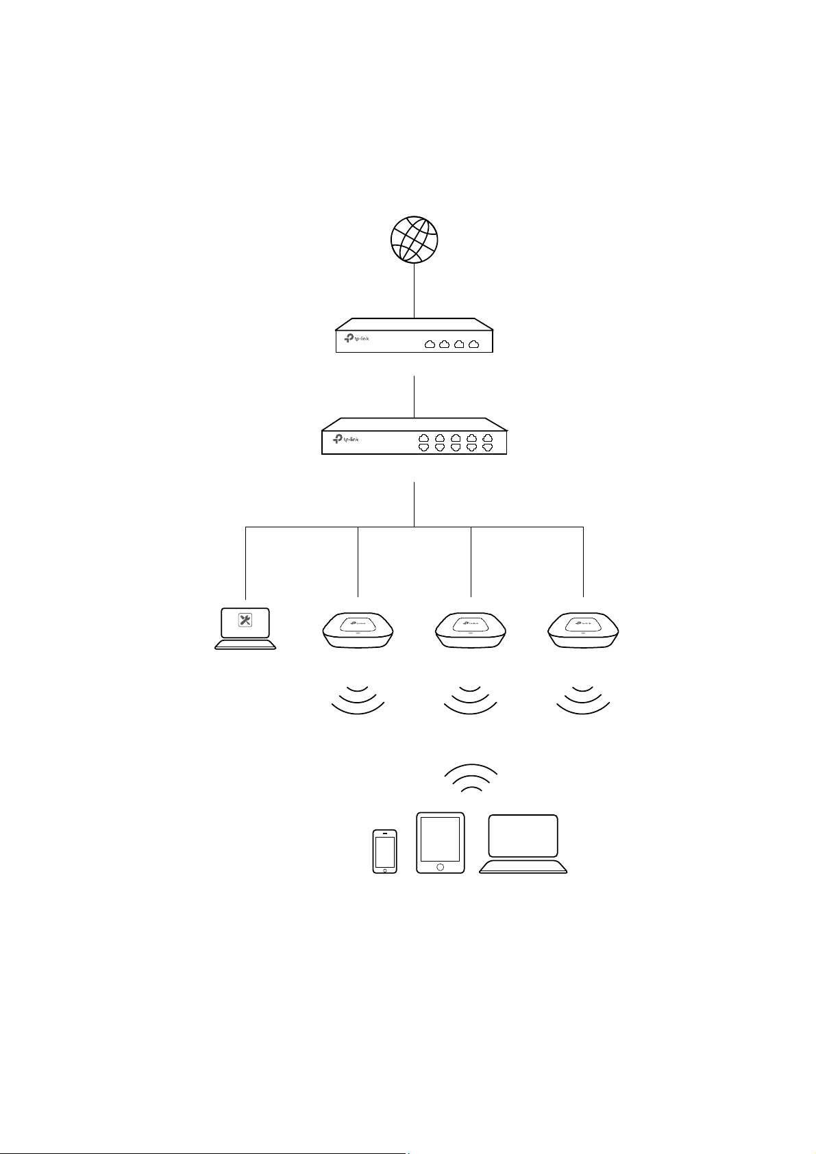
A typical network topology for the EAP is shown below.
Figure 2-1 Typical Topology
To deploy an EAP in your local network, a DHCP server is required to assign IP addresses
to the EAP and clients. Typically, a router acts as the DHCP server. A computer running
the EAP Controller software can locate in the same or different subnet with the EAPs.
3

The EAP can be managed by the EAP Controller software, which is a management
software specially designed for the TP-Link EAP devices on a local wireless network,
allowing you to centrally configure and monitor mass EAP devices using a web browser
on your PC. For more information about the EAP Controller, please find the EAP
Controller User Guide from our official website:
http://www.tp-link.com/en/support/download/
4

Chapter 3 Management Mode
TIPS:
Proceed to the following chapters for information on using the EAP in standalone mode.
Auranet series products can either work under the control of the EAP Controller software
or work independently as a standalone access point.
When user establishes a large-scale wireless network, the management of every single
AP in the network is complex and complicated. With the EAP Controller software, you
can centrally manage the mass APs simply in a web browser.
The Standalone mode applies to a relatively small-sized wireless network. EAPs in the
Standalone mode cannot be managed centrally by the EAP Controller software.
3.1 Standalone Mode
By default, the EAP works independently as a standalone access point. By entering the
IP address of the standalone EAP, you can log in to its web interface and perform
configurations.
The factory default IP address configuration of the EAP is DHCP (Dynamic Host
Configuration Protocol). Before you access the web interface of the EAP, please make
sure the DHCP server works properly. Typically, a router acts as the DHCP server.
Follow the steps below to log in to the web interface of a standalone EAP.
1. Launch a web browser, enter the DHCP address in the address field and press the
Enter key.
2. Enter admin (all lowercase) for both username and password.
3.2 Managed Mode
The EAP will become a managed AP once it is adopted via the EAP Controller software.
Users can manage the AP via a web browser. Refer to the EAP Controller User Guide
from our website at www.tp-link.com to know more about EAP Controller software.
3.3 Switch to Standalone Mode
The web interface of a specific EAP is not available once this EAP is adopted by the EAP
Controller. You can
AP. Refer to the EAP Controller User Guide from our website at www.tp-link.com to learn
more.
Forget
the EAP via the EAP Controller to turn it back as a standalone
5
On
Network
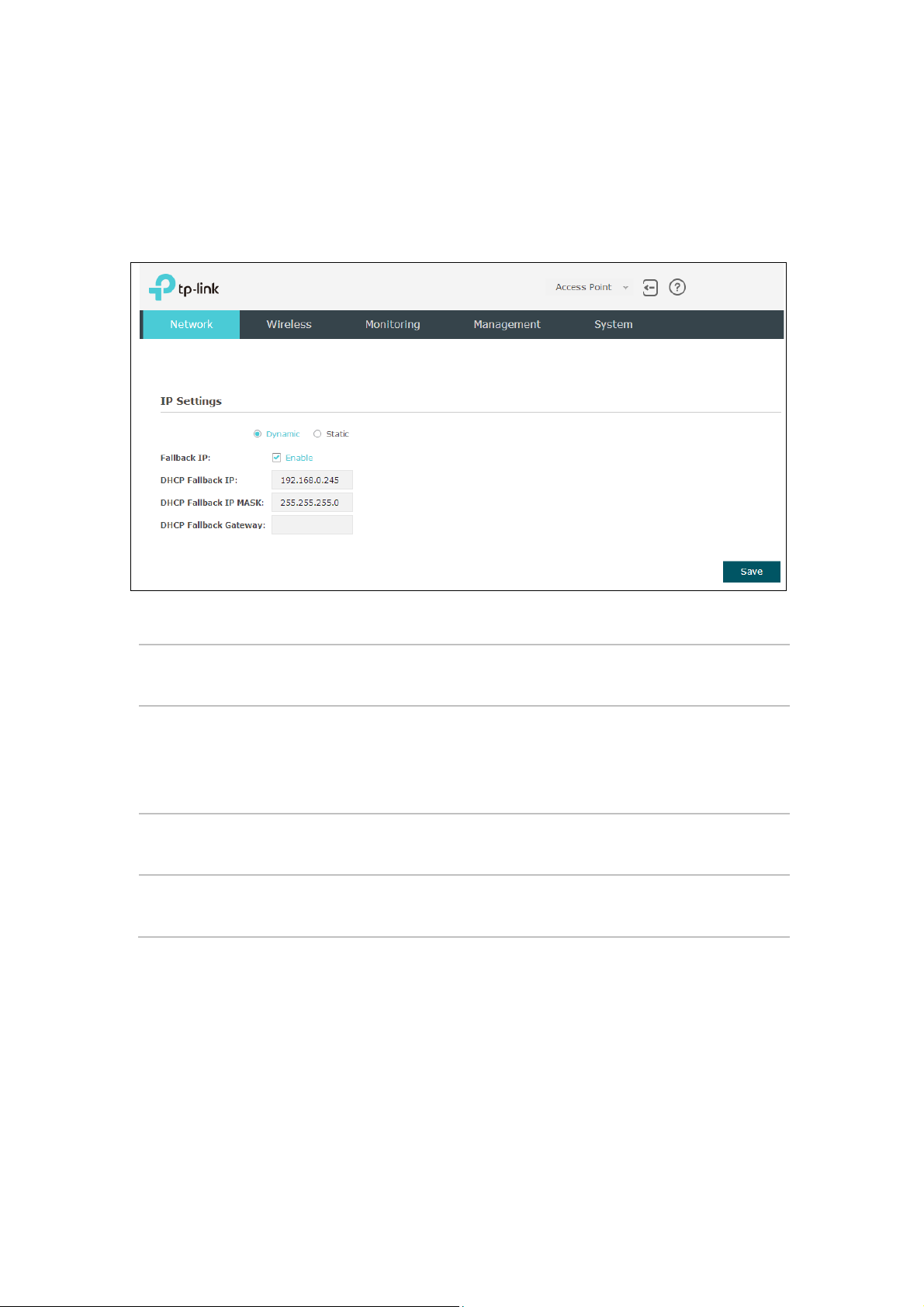
Chapter 4 Network
page you can configure the IP address of the standalone EAP.
Figure 4-1 Network Page
Dynamic/Static:
Fallback IP:
DHCP Fallback
IP/IP MASK:
DHCP Fallback
Gateway:
By default, the EAP device obtains an IP address from a DHCP server
(typically a router). Select Static to configure IP address manually.
If the EAP fails to get a dynamic IP address from a DHCP server within
ten seconds, the fallback IP will work as the IP address of the device.
After that, however, the device will keep trying to obtain an IP address
from the DHCP server until it succeeds.
Enter the fallback IP/IP mask.
Enter the fallback gateway.
6
Chapter 5 Wireless
Wireless
and Rogue AP Detection, is shown below.
page, consisting of Wireless Settings, Portal, MAC Filtering, Scheduler, QoS
Figure 5-1 Wireless Page
7
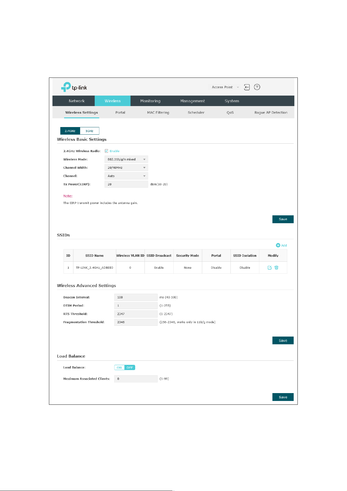
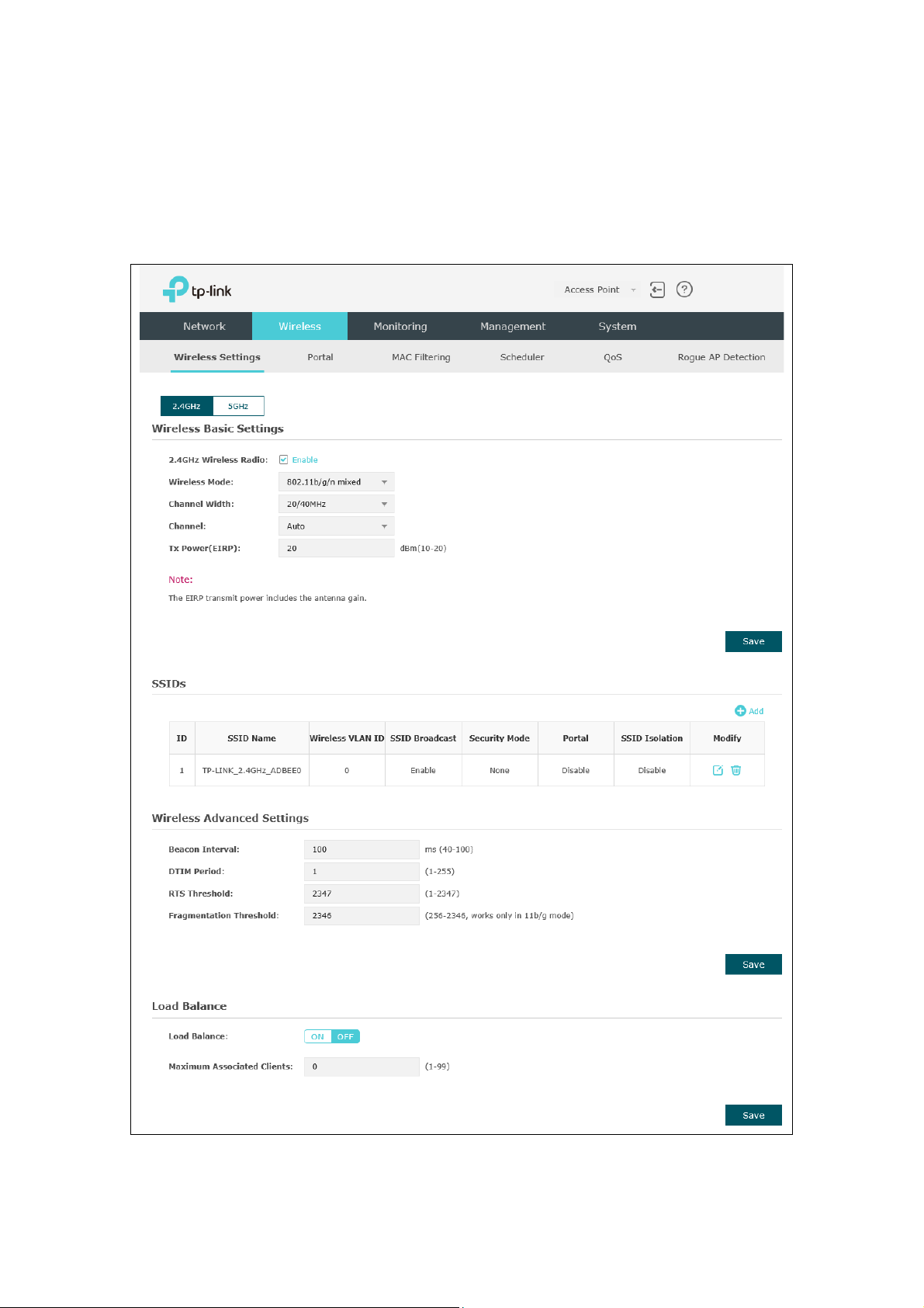
5.1 Wireless Settings
Wireless Settings
Following is the page of
.
Figure 5-2 Wireless Settings Page
8
way clients supporting any one of these modes can access your
802.11a/n/ac, in which way clients supporting any one of these modes
ut. However, users may choose lower
bandwidth can concentrate higher transmit power,
TIPS:
Proceed to the following chapter for information on configuring the wireless network of
the EAP. The configuring information of 2.4GHz is taken as the example.
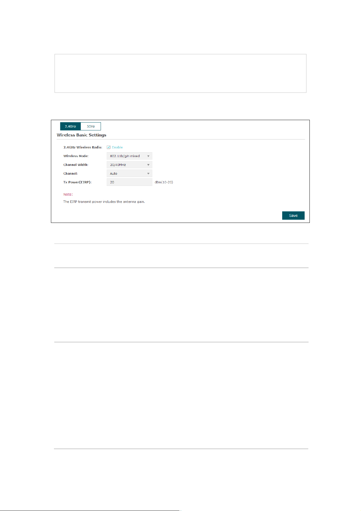
5.1.1 Wireless Basic Settings
Figure 5-3 Wireless Basic Settings
2.4GHz
Wireless Radio:
Wireless Mode: Select the protocol standard for the wireless network.
Channel Width: Select the channel width of this device.
Check the box to enable 2.4GHz Wireless Radio.
For 2.4GHz network, we recommend that select 802.11b/g/n, in which
wireless network.
For 5GHz network, we recommend that select 802.11a/n or
can access your wireless network.
According to IEEE 802.11n standard, using a higher bandwidth can
increase wireless throughp
bandwidth due to the following reasons:
1. To increase the available number of channels within the limited total
bandwidth.
2. To avoid interference from overlapping channels occupied by other
devices in the environment.
3. Lower
increasing stability of wireless links over long distances.
9
Channel:
Select the channel used by this device to improve wireless
If the maximum transmit power is set to be larger than local regulation
NOTE
In most cases, it is unnecessary to select maximum transmit
power. Selecting larger transmit power than needed may cause
interference to neighborhood. Also it consumes more power and will
reduce longevity of the device. Select a certain transmit power is
performance. 1/2412MHz means the Channel is 1 and the frequency is
2412MHz. By default, channel is automatically selected.
Tx power: Enter the transmit power value. By default, the value is 20.
allows, the maximum Tx power regulated will be applied in actual
situation.
:
enough to achieve the best performance.
5.1.2 SSIDs
SSIDs can work together with switches supporting 802.1Q VLAN. The EAP can build up
to eight virtual wireless networks per radio for users to access. At the same time, it adds
different VLAN tags to the clients which connect to the corresponding wireless network.
It supports maximum 8 VLANs per radio. The clients in different VLAN cannot directly
communicate with each other.
Clients connected to the device via cable do not belong to any VLAN. Thus wired client
can communicate with all the wireless clients despite the VLAN settings.
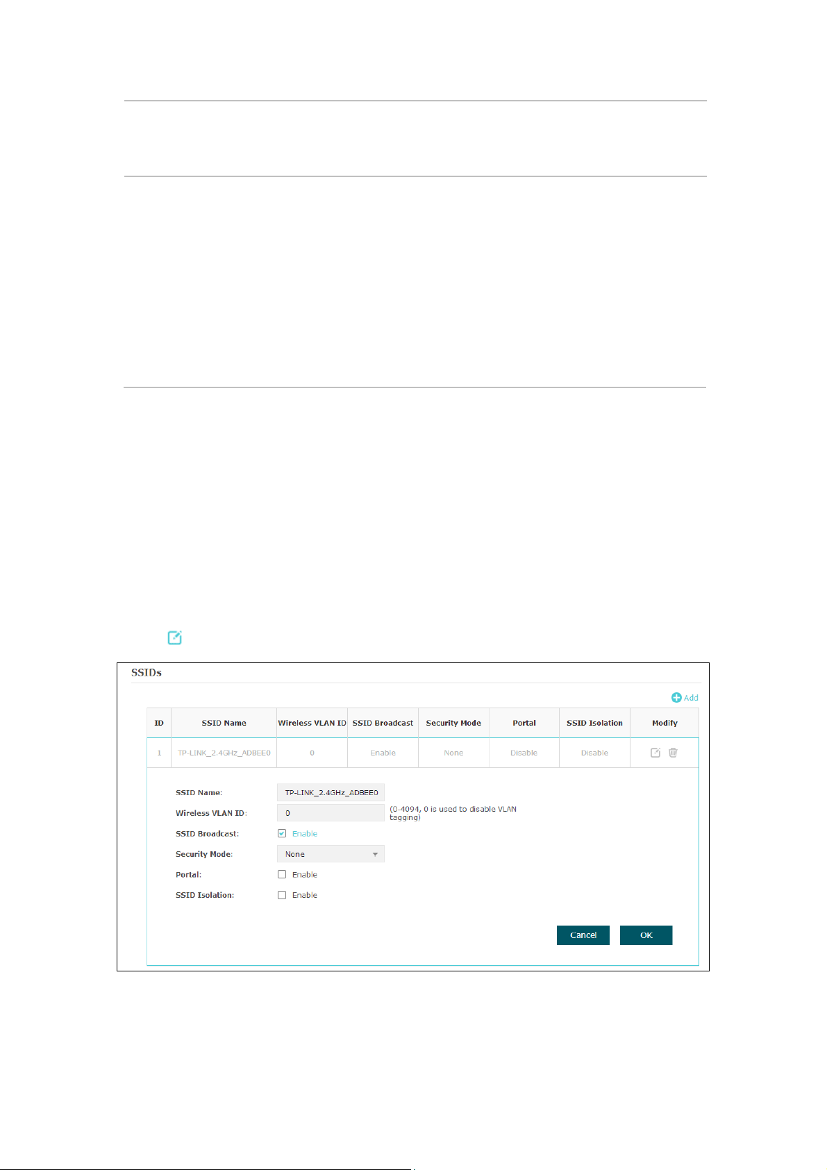
Click in the Modify column, the following content will be shown.
Figure 5-4 SSIDs
10

Click to add up to 8 wireless networks per radio.
environment, as thus hosts can find the wireless network identified by this
SSID. If SSID Broadcast is not enabled, hosts must enter the AP’s SSID
s network. For the security of
PSK is
Portal provides authentication service for the clients who want to access
NOTE:
not be able to access the wireless network. If WEP is applied in 11b/g/n mode (in the
2.4GHz frequency band) or 11a/n (in the 5GHz frequency band), the device may work at a
low transmission rate.
SSID Name: Enter up to 32 characters as the SSID name.
Wireless
VLAN ID:
SSID
Broadcast:
Security
Mode:
Portal:
SSID
Isolation:
Set a VLAN ID for the wireless network.
Wireless networks with the same VLAN ID are grouped to a VLAN.
Enable this function, AP will broadcast its SSID to hosts in the surrounding
manually to connect to this AP.
Select the security mode of the wireles
wireless network, you are suggested to encrypt your wireless network. This
device provides three security modes: WPA-Enterprise, WPA-PSK (WPA
Pre-Shared Key) and WEP (Wired Equivalent Privacy). WPArecommended. Settings vary in different security modes as the details are
in the following introduction. Select None and the hosts can access the
wireless network without password.
the wireless local area network. For more information, refer to 5.2 Portal.
After Portal is enabled, the configurations in 5.2 Portal will be applied.
After enabling SSID Isolation, the devices connected in the same SSID
cannot communicate with each other.
Modify:
Click to open the page to edit the parameters of SSID.
Click to delete the SSID.
Following is the detailed introduction of security mode: WEP, WPA-Enterprise and
WPA-PSK.
WEP
WEP (Wired Equivalent Privacy), based on the IEEE 802.11 standard, is less safe than
WPA-Enterprise or WPA-PSK.
WEP is not supported in 802.11n mode. If WEP is applied in 802.11n mode, the clients may
11
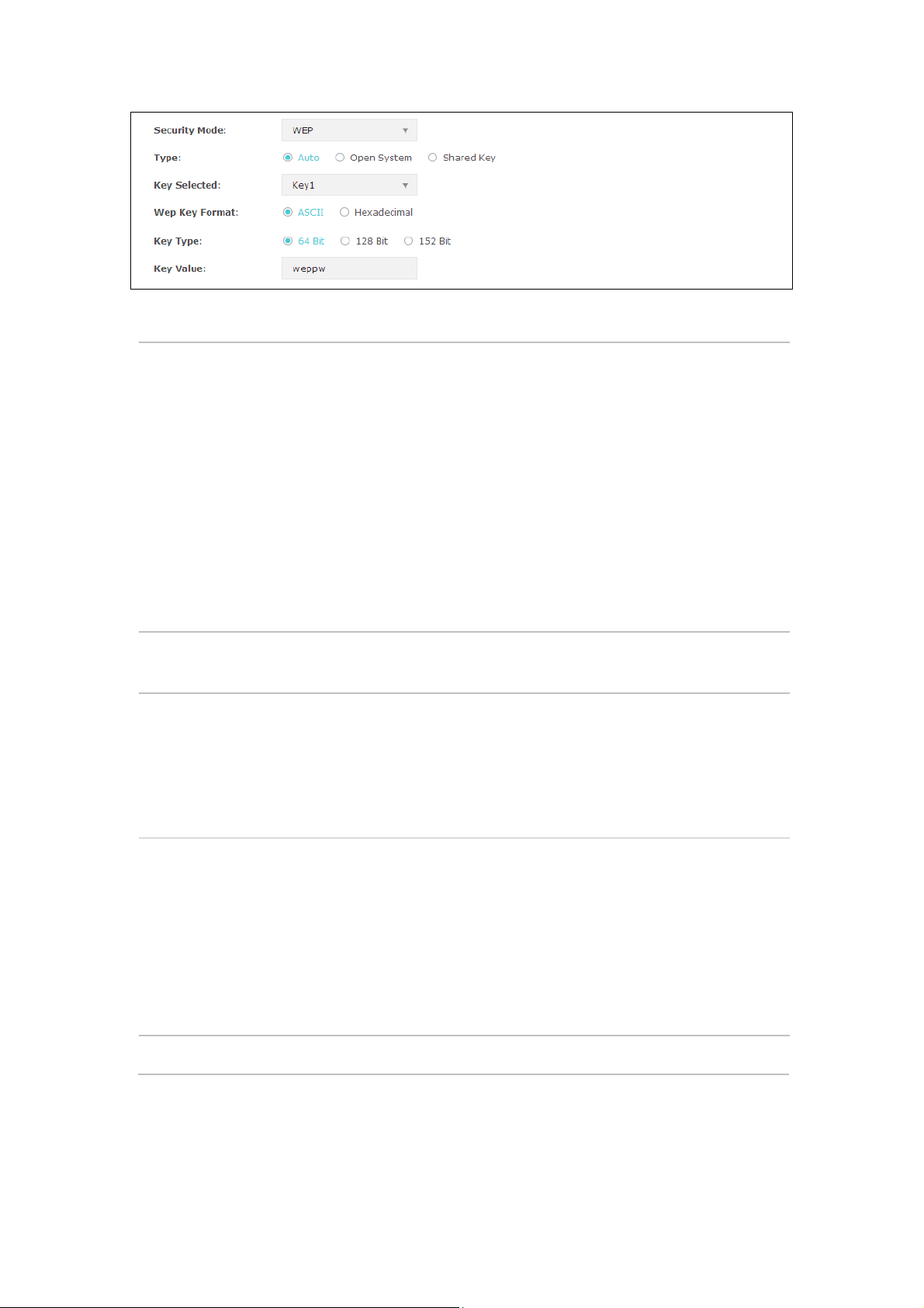
Figure 5-5 Security Mode-WEP
authentication and associate with the wireless network without
password. However, correct password is necessary for data
You can configure four keys in advance and select one as the present
: Hexadecimal format stands for any combination of
Type: Select the authentication type for WEP.
Auto: The default setting is Auto, which can select Open System or
Shared Key automatically based on the wireless station's capability and
request.
Open System: After you select Open System, clients can pass the
transmission.
Shared Key: After you select Shared Key, clients has to input password
to pass the authentication, or it cannot associate with the wireless
network or transmit data.
Key Selected:
valid key.
Wep Key
Format:
Select the wep key format ASCII or Hexadecimal.
ASCII: ASCII format stands for any combination of keyboard characters
in the specified length.
Hexadecimal
hexadecimal digits (0-9, a-f, A-F) in the specified length.
Key Type: Select the WEP key length for encryption.
64-bit: You can enter 10 hexadecimal digits (any combination of 0-9, a-
f, A-F without null key) or 5 ASCII characters.
128-bit: You can enter 26 hexadecimal digits (any combination of 0-9,
a-f, A-F without null key) or 13 ASCII characters.
152-bit: You can enter 32 hexadecimal digits (any combination of 0-9,
a-f, A-F without null key) or 16 ASCII characters.
Key Value: Enter the key value.
12
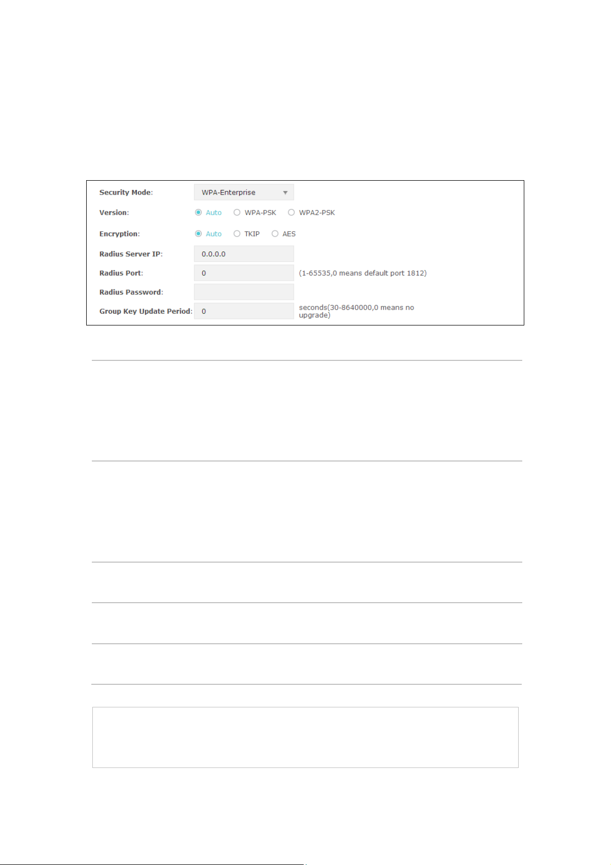
WPA-Enterprise
PSK automatically based on the
or AES (Advanced Encryption Standard) automatically based on the
NOTE:
the clients may not be able to access the wireless network of the EAP. If TKIP is applied in
Based on RADIUS server, WPA-Enterprise can generate different passwords for
different users and it is much safer than WPA-PSK. However, it costs much to maintain
and is more suitable for enterprise users. At present, WPA-Enterprise has two versions:
WPA-PSK and WPA2-PSK.
Figure 5-6 Security Mode_WPA-Enterprise
Version: Select one of the following versions:
Encryption:
RADIUS Server
IP/Port:
RADIUS
Password:
Group Key
Update period:
Auto: Select WPA-PSK or WPA2-
wireless station's capability and request.
WPA-PSK: Pre-shared key of WPA.
WPA2-PSK: Pre-shared key of WPA2.
Select the encryption type, including Auto, TKIP, and AES. The default
setting is Auto, which can select TKIP (Temporal Key Integrity Protocol)
wireless station's capability and request. AES is more secure than TKIP
and TKIP is not supported in 802.11n mode. It is recommended to select
AES as the encryption type.
Enter the IP address/port of the RADIUS server.
Enter the shared secret of RADIUS server to access the RADIUS server.
Specify the group key update period in seconds. The value can be either
0 or 30-8640000 seconds.
Encryption type TKIP is not supported in 802.11n mode. If TKIP is applied in 802.11n mode,
13
 Loading...