

Page 1

Installation Guide
Wireless N Access Point
EAP110/EAP120/EAP220
Page 2

Page 3

CONTENTS
Network Topology ————————————————————— 01
Hardware Overview ———————————————————— 02
Hardware Installation ——————————————————— 05
1. Installation Requirements ....................................................... 05
2. Mounting Bracket ................................................................... 05
3. Installation ............................................................................ 06
4. Power Supply ......................................................................... 11
Software Conguration —————————————————— 13
Q&A ——————————————————————————— 14
Specications ——————————————————————— 15
About This Installation Guide
This guide is designed to familiarize you with the general layout of the EAP110,
EAP120 and EAP220, describe how to perform the hardware installation, and how
to configure the EAP Controller software in your network. Your EAP has more
features and functionalities which can be found in the User Guide.
Conventions
Unless otherwise noted, the EAP or the device mentioned in this guide stands for
300Mbps Wireless N Access Point EAP110, Wireless N Gigabit Access Point EAP120
and EAP220.
Page 4
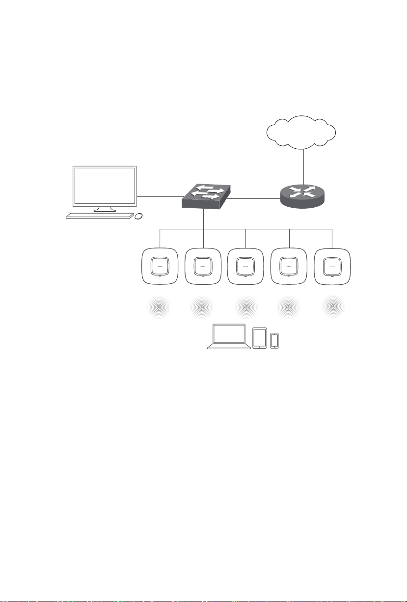
Network Topology
A typical network topology for the EAP is shown below.
Controller Host
Internet
EAP
Switch
Router
Controller
EAP
Clients
To deploy an EAP in your local network, a DHCP server is required to assign IP
addresses to the EAP and clients. Typically, a router acts as the DHCP server.
Ensure the EAPs are in the same subnet with the Controller Host in which the EAP
Controller software is installed.
The EAP can be managed by the EAP Controller software, which is a management
software specially designed for the TP-LINK EAP devices on a local wireless
network, allowing you to centrally configure and monitor mass EAP devices using
a web browser on your PC. The EAP can also work independently as a standalone
device.
01
Page 5
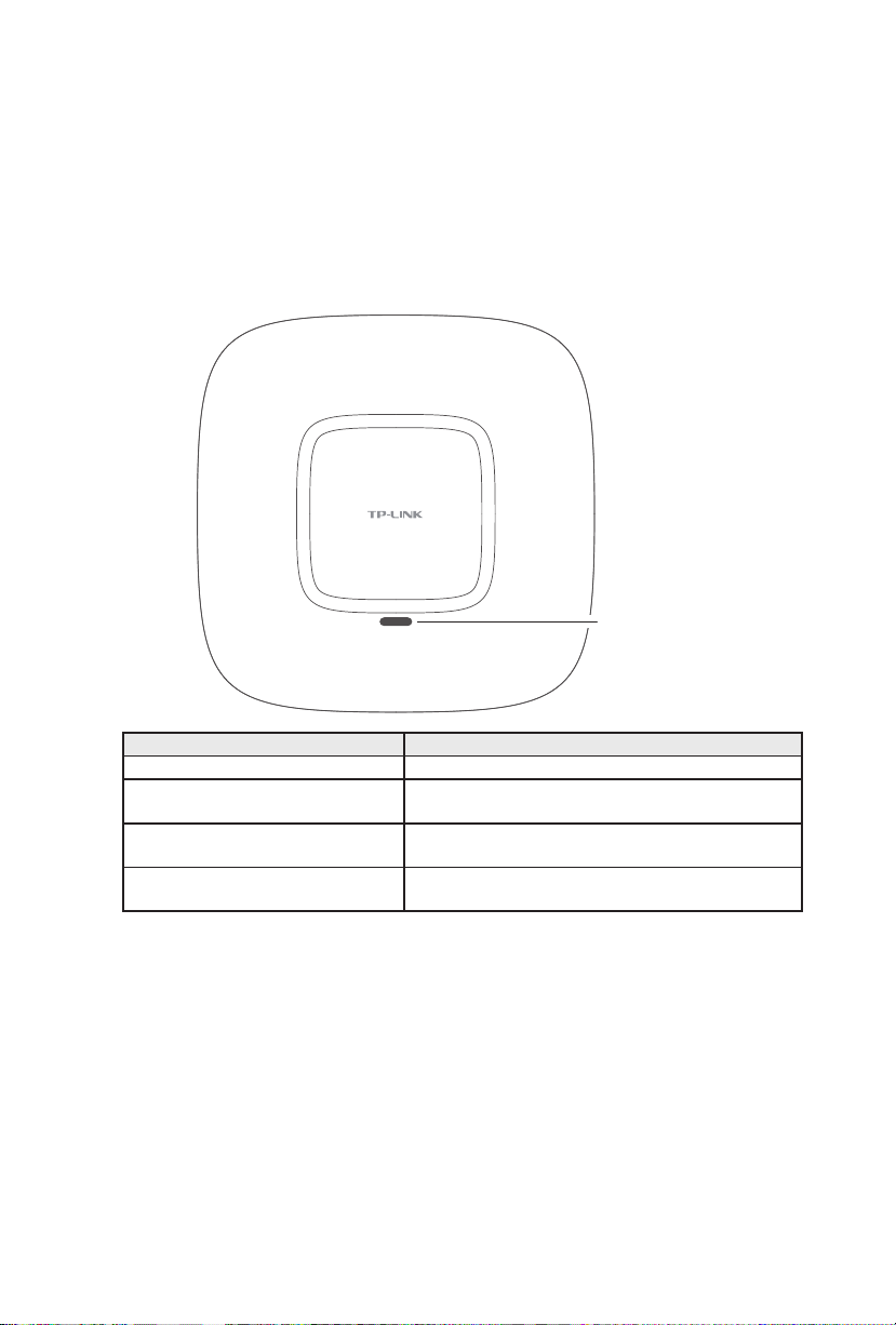
Hardware Overview
1. LED
EAP110, EAP120 and EAP220 have the same LED status and corresponding
indications.
System LED
LED Status Indication
Solid green The device is working properly.
Flashing red System errors. RAM, Flash, Ethernet, WLAN or
Flashing yellow Firmware update is in progress. Do not disconnect
Double-flashing red, green, yellow The device is being reset to its factory default
firmware may be malfunctioning.
or power off the device.
settings.
02
Page 6
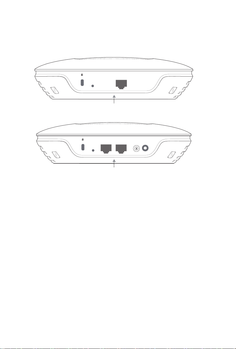
2. Interface Panel
ARROW 1
■
EAP110
RESET ETHERNET
■
EAP120/EAP220
ON/OFF
RESET
CONSOLE ETHERNET
ARROW 1
Please note that EAP110 does not have the CONSOLE port, POWER port or ON/OFF
button. The interface panel components of the EAP, from left to right, are described
in the following list.
POWER
Kensington Security Slot
Secure the lock (not provided) into the security slot to prevent the device from
being stolen.
RESET
With the device powered on, press and hold the RESET button for about 8 seconds
until the LED ashes red, then release the button. The device will restore to factory
default settings.
CONSOLE
This port is used to connect to the serial port of a computer or a terminal to check
and monitor system information of EAP120/EAP220.
Note: CLI commands are not available in current software version. We will release
a new version supporting CLI commands soon. Please pay close attention to our
ofcial website.
03
Page 7

ON/OFF
Press this button to turn on/off the EAP120/EAP220.
POWER
The power port is used to connect the EAP120/EAP220 to an electrical wall outlet
via power adapter. Please only use the provided power adapter. Refer to next
chapter 4.Power Supply to learn how to power the EAP120/EAP220 via power
adapter.
ARROW 1
This arrow is used to align with ARROW 2 on the mounting bracket to lock the EAP
into place. Please refer to next chapter 2.Mounting Bracket to locate ARROW 2.
ETHERNET
For EAP110, this port is used to connect to the POE port of the provided PoE
adapter for both data transmission and power supply through Ethernet cabling.
For EAP120/EAP220, this port is used to connect to a router or a switch to transmit
data or to a PSE (Power Sourcing Equipment), such as a PoE switch, for both data
transmission and Power over Ethernet (PoE) through Ethernet cabling.
■
Passive PoE Adapter
The PoE adapter is ONLY provided with EAP110 for power supply. Refer to next
chapter 4.Power Supply to learn more about power supply for EAP110.
Power LED
Power LED
The Power LED indicates the status of the electric current: green (0-0.8A), red
(0.8A-1A).
POE Port
This port is used to connect to the ETHERNET port of EAP110.
LAN Port
This port is used to connect to your LAN.
04
Page 8

Hardware Installation
The EAP can be wall-mounted or ceiling-mounted. Please suitably arrange your
wire layout before mounting the EAP. We take EAP110 as example to explain the
installation. EAP110 can be powered via the provided PoE adapter, while EAP120
and EAP220 can be powered via a PoE switch or the provided power adapter.
1. Installation Requirements
Before installation, check the package contents for the following items:
EAP Mounting Bracket
Wing Nuts (3) Washers (3)
Plastic Wall
Anchors (3)
Installation Guide
Self-tapping
Screws (3)
Pan-head
Screws (3)
Other installation equipments may require, including a pencil, ruler, drill, drill bit,
screwdriver and a ladder.
2. Mounting Bracket
The following figure describes the layout of the mounting bracket.
ARROW 2 is used to align
with ARROW 1 under the
interface panel
Ceiling mounting slot
Wall mounting slot
Locking clip
05
Page 9

3. Installation
■
Ceiling Mounting
Note:
■
Make sure the thickness of the ceiling is less than 18mm and
the ceiling can bear at least five kilograms.
■
It is NOT recommended to mount the EAP on a low-strength
material, such as gypsum ceiling panel. If no other choice is
available, make sure you add a piece of strong material under
the wing nuts to ensure the EAP is mounted solidly.
1. Remove the ceiling tile.
2. Place the mounting bracket in the center of the ceiling tile. Mark the positions
of the three mounting slots and a hole for the Ethernet cable to feed through.
L
L≈40mm
Mark of the hole for Ethernet
cable to feed through
06
Page 10

3. Use a drill with the appropriate size drill bit to drill three 4mm holes for
the pan-head screws, and drill a 10mm hole for the Ethernet cable to feed
through.
4mm hole for mounting bracket
10mm hole for Ethernet cable feed
4. Secure the mounting bracket to the ceiling tile using the pan-head screws,
washers and wing nuts, as shown below.
07
Wing nut
Washer
Hole to feed the Ethernet cable
Hole to feed the screw
Pan-head screw
Page 11

5. Attach the EAP to the mounting bracket by aligning ARROW 1 with ARROW 2,
as shown below.
ARROW 1
ARROW 2
RESET
ETHERNET
6. Turn the EAP clockwise until it locks into place.
08
Page 12

7. Feed the Ethernet cable through the hole and set the ceiling tile back into
place.
8. Connect the Ethernet cable to the ETHERNET port.
■
Wall Mounting
There are two wall-mounting slots on the back of the mounting bracket. To mount
the EAP on a wall, please follow the steps below.
1. Make two small pencil marks on the wall. Make sure the two marks are level
and should be 98.6mm apart.
2. Use a drill with the appropriate size drill bit to drill two 4mm holes through the
center of your marks.
Wall
4mm hole
3. Insert the plastic wall anchors into the 4mm holes and drive the self-tapping
screws into the anchors.
09
Page 13

4. Attach the EAP to the mounting bracket by aligning ARROW 1 with ARROW 2.
ARROW 1
ARROW 2
RESET
ETHERNET
5. Turn the EAP clockwise until it locks into place.
6. Hang the EAP on the screws. Make sure the EAP is firmly seated against the
wall.
7. Connect the Ethernet cable to the ETHERNET port on the EAP.
10
Page 14

4. Power Supply
POE LAN
■
EA P110
The EAP110 can be powered with the provided PoE adapter.
3
POE LAN
PoE Adapter
Switch
EAP110
1 2
(Up to 100m)
1. Connect the ETHERNET port of EAP110 to the POE port of the PoE adapter
through an Ethernet cable. The cable length can be up to 100 meters.
2. Connect the Ethernet cable from the switch to the LAN port of the PoE
adapter.
3. Plug the female connector of the power cord into the PoE adapter, and the
male connector to a power outlet.
11
Page 15

■
EAP120/EAP220
EAP120/EAP220 can be powered via a PSE device (such as a PoE switch) or a
power adapter.
Via PoE Switch
EAP120/EAP220
2
1
PoE Switch
1. Connect the Ethernet cable from the PoE switch to the ETHERNET port of
EAP120/EAP220.
2. Press the ON/OFF button on the interface panel of EAP120/EAP220.
Via Power Adapter
Switch
EAP120/EAP220
2
Socket
1
1. Plug one end of the provided power adapter into the power port of EAP120/
EAP220, and the other end to a standard electrical wall socket.
2. Press the ON/OFF button on the interface panel of EAP120/EAP220.
12
Page 16

Software Configuration
The following content will guide you to quickly set up a wireless network
connection with mass EAPs, and log in to the EAP Controller management interface
to manage the EAPs.
Internet
Controller Host
EAP
Switch
Router
Controller
EAP
Step 1: EAP Controller Installation
Follow the step-by-step instructions to complete the EAP Controller installation on
the Controller Host.
Note: The EAP Controller application file can be found on the resource CD or
downloaded from our website http://www.tp-link.com/en. Refer to the EAP
Controller User Guide to learn how to perform the installation.
Step 2: Configuring the Controller Software
Launch the EAP Controller and finish the configuration wizard to create a primary
wireless network.
Step 3: More Configurations
After the primary network is created, a login screen will appear. Enter the admin
name and password you created and click Sign In. You will be directed to the
management interface in which you can perform more advanced configurations.
Refer to the EAP Controller User Guide to learn more advanced configurations .
13
Page 17

Q&A
What is the maximum cable length between the EAP110 and
Q1.
the provided PoE adapter?
100 meters. The quality of the Ethernet cable may influence the
reception of the power supply.
Could the EAP work as a standalone device if it had been
Q2.
adopted by the EAP Controller?
No. By default, the EAP works as a standalone device. It will function
as a Managed AP once adopted by the EAP Controller. You can
this AP on the Controller management interface to turn it back as a
standalone device.
Can I manage the EAP devices on a host without the EAP
Q3.
Controller server?
Yes. Keep the EAP Controller software running on the Controller Host,
sign in to the EAP Controller using https://x.x.x.x:8043/login in
which x.x.x.x is the IP address of the Controller Host and 8043 is the
default port number for the server.
For example, the IP address of Controller Host is 192.168.0.100, you
can enter https://192.168.0.100:8043/login on other hosts in the
same LAN to reach the login page of the EAP Controller.
Forget
14
Page 18

Specifications
HARDWARE FEATURES
Model EAP110 EAP120 EAP220
Interface Kensington lock slot
RESET button
ETHERNET:
10/100Mbps
Ethernet port (RJ-
45)
Power Supply 24V/1A passive PoE
adapter (included)
Maximum Power
Consumption
Antenna 2*3dBi embedded 2*4dBi embedded 4*4dBi embedded
Mounting Ceiling/Wall mounting (kits included)
Certication CE, FCC, RoHS
Operating
Temperature
Operating
Humidity
WIRELESS FEATURES
Wireless
Frequency
Wi-Fi Standard IEEE 802.11b/g/n IEEE 802.11a/b/g/n
Maximum Data
Rate
Max RF
Transmission
(1)
Power
Multiple SSIDs Up to eight per radio
Captive Portal
Authentication
Wireless
Security
7.7 W 4.4W 9.6W
0℃~40℃ (32℉~104℉)
10%~90% non-condensing
2.4GHz 2.4GHz & 5GHz
Up to 300Mbps Up to 600Mbps
23dBm 2.4GHz:23dBm
Support
WEP
WPA/WPA2-PSK
WPA/WPA2-Enterprise
ETHERNET: 10/100/1000Mbps Ethernet port (RJ-
45)
CONSOLE port (RJ-45)
ON/OFF button
Power connector (DC-2)
PoE(802.3af-compliant,
36-57VDC, 0.2A Max)
or external 12VDC/1A
power supply
PoE (802.3af-compliant,
36-57VDC, 0.4A Max)
or external 12VDC/1.5A
power supply
5GHz:20dBm
15
Maximum transmission power may vary in different countries or regions.
Page 19

Page 20

COPYRIGHT & TRADEMARKS
Specifications are subject to change without notice. is a registered
trademark of TP-LINK TECHNOLOGIES CO., LTD. Other brands and product names
are trademarks of their respective holders. No part of the specifications may be
reproduced in any form or by any means or used to make any derivative such
as translation, transformation, or adaptation without permission from TP-LINK
TECHNOLOGIES CO., LTD. Copyright © 2015 TP-LINK TECHNOLOGIES CO., LTD.
All rights reserved.
Website: http://www.tp-link.com
Tel: +86 755 26504400
E-mail: support@tp-link.com
710650 5122 REV1. 0.0
 Loading...