

Page 1

User Guide
EAP Controller Software
REV1.0.0
1910011273
Page 2

EAP Controller User Guide Contents
CONTENTS
Chapter 1
1.1 System Requirements ...................................................................................................................................... 1
1.2 Network Topology ............................................................................................................................................ 1
1.3 Software Installation ........................................................................................................................................ 2
1.4 Quick Setup ......................................................................................................................................................... 4
System Setup ............................................................................ 1
Chapter 2 Interface .................................................................................... 7
Chapter 3 Monitor ..................................................................................... 9
3.1 Map Tab ................................................................................................................................................................ 9
3.1.1 Add Custom Maps ................................................................................................................................... 9
3.1.2 Set the Map Scale ................................................................................................................................. 10
3.1.3 Place APs onto the Map ..................................................................................................................... 11
3.2 Statistics Tab ..................................................................................................................................................... 13
3.2.1 View the Client Distribution on SSID............................................................................................. 14
3.2.2 Quick Look .............................................................................................................................................. 14
3.2.3 View Current Usage-Top APs ............................................................................................................ 15
3.2.4 View Recent Activities......................................................................................................................... 15
3.3 Access Points Tab ........................................................................................................................................... 16
3.4 Clients Tab ......................................................................................................................................................... 18
3.5 Insight Tab......................................................................................................................................................... 19
3.5.1 Clients Statistics .................................................................................................................................... 19
3.5.2 Untrusted Rogue APs .......................................................................................................................... 19
3.5.3 Trusted Rogue APs ............................................................................................................................... 19
3.6 Lo g Tab ............................................................................................................................................................... 20
Chapter 4 Global Setting ......................................................................... 21
4.1 Wireless Settings ............................................................................................................................................ 21
I
Page 3

EAP Controller User Guide Contents
4.1.1 Basic Wireless Setting ......................................................................................................................... 21
4.1.2 Advanced Wireless Setting ............................................................................................................... 24
4.2 Wireless Control .............................................................................................................................................. 25
4.2.1 Portal ......................................................................................................................................................... 25
4.2.2 Free Authentication Policy ................................................................................................................ 29
4.2.3 MAC Filter ................................................................................................................................................ 30
4.2.4 MAC Filter Association ........................................................................................................................ 31
4.2.5 Scheduler ................................................................................................................................................ 32
4.2.6 Scheduler Association ........................................................................................................................ 33
4.2.7 QoS ............................................................................................................................................................ 34
4.3 System ................................................................................................................................................................ 37
4.3.1 Log Setting.............................................................................................................................................. 37
4.3.2 Device Account ..................................................................................................................................... 38
4.3.3 LED ............................................................................................................................................................. 39
4.3.4 Backup&Restore .................................................................................................................................... 39
4.3.5 Batch Upgrade ....................................................................................................................................... 39
4.3.6 Country/Region .................................................................................................................................... 40
4.3.7 About ........................................................................................................................................................ 40
4.4 Admin ................................................................................................................................................................. 40
4.4.1 User Settings .......................................................................................................................................... 41
4.4.2 Role ............................................................................................................................................................ 42
4.4.3 Controller Settings ............................................................................................................................... 43
Chapter 5 AP Details ................................................................................ 45
5.1 Details ................................................................................................................................................................. 45
5.1.1 Overview ................................................................................................................................................. 45
5.1.2 LAN ............................................................................................................................................................ 45
5.1.3 Radio ......................................................................................................................................................... 46
5.2 User ..................................................................................................................................................................... 46
5.3 Guest ................................................................................................................................................................... 47
II
Page 4

EAP Controller User Guide Contents
5.4 Configuration .................................................................................................................................................. 47
5.4.1 Basic Config ............................................................................................................................................ 47
5.4.2 IP Setting ................................................................................................................................................. 48
5.4.3 Radio ......................................................................................................................................................... 49
5.4.4 Load Balance .......................................................................................................................................... 51
5.4.5 SSID Override ......................................................................................................................................... 51
5.4.6 Rogue AP Detection ............................................................................................................................ 52
5.4.7 Forget this AP ......................................................................................................................................... 53
Chapter 6 Application Example .............................................................. 54
6.1 Map Monitor .................................................................................................................................................... 54
6.2 Portal Authentication ................................................................................................................................... 54
III
Page 5
EAP Controller User Guide Chapter 1 System Setup
Chapter 1 System Setup
The EAP Controller is a management software specially designed for the TP-LINK EAP devices on a
business wireless network. It allows you to centrally manage masses of EAP devices using a web browser
on your PC. Moreover, it is particularly worth mentioning that it allows you to configure EAPs in batches.
The EAP Controller has sufficient monitoring features. Graphically displaying the location and visual
coverage of the managed EAP devices, the Controller can also real-time monitor the running condition of
each EAP in the LAN.
This User Guide is applicable to the EAP Controller software and all of the EAP series Business Wi-Fi Access
Point models.
1.1 System Requirements
The computer that installs the EAP Controller software has the following requirements:
Operating System
Microsoft Windows XP/Vista/7/8.
Web Browser
Mozilla Firefox 32 (or above), Google Chrome 37 (or above), Opera 24 (or above), or Microsoft Internet
Explorer 8-11.
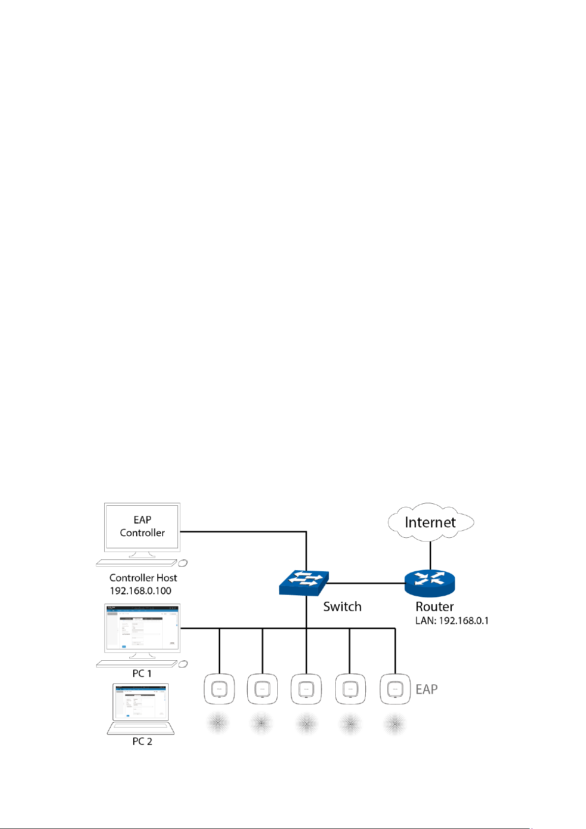
1.2 Network Topology
Typical network topology is shown below.
1
Page 6
EAP Controller User Guide Chapter 1 System Setup
A DHCP Server
To deploy EAPs in your local network, a DHCP server is required to assign IP addresses to the EAP devices
and clients. Typically, a router acts as the DHCP server. It’s assumed that the IP address of the LAN of the
router is 192.168.0.1.
Management Hosts
In the LAN, only one management host needs to install the EAP Controller software, called Controller Host.
For other hosts’ convenient login to the EAP Controller interface, it’s recommended to set a static IP
address to the Controller Host. The IP address must be in the same subnet with the DHCP server. We take
192.168.0.100 as an example in the topology figure.
PC 1 and PC 2 do not need to install the EAP Controller software. After you have configured the wireless
network with the EAP Controller on the Controller Host, other computers (PC 1 and PC 2) in the same LAN
can use the way of “IP:port” to log into the EAP Controller to monitor the wireless network. For the details,
please refer to the note of Step 6 at Quick Setup.
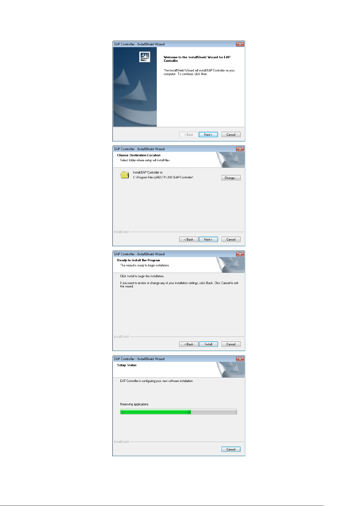
1.3 Software Installation
The EAP Controller software just needs to be installed once when you initially create an EAP network. You
can get the installation software of EAP Controller on the resource CD provided with your EAP device or
download it from our website http://www.tp-link.com/en/support/download/. Perform the following
installation steps to properly install the EAP Controller software:
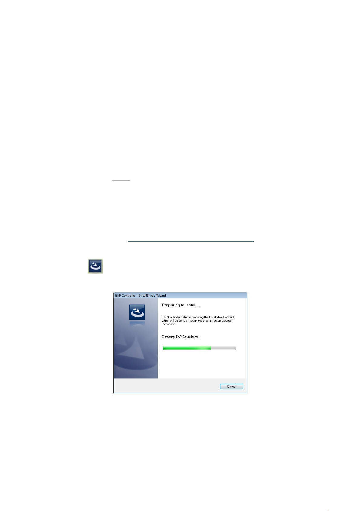
Step 1: Launch EAP Controller.exe. The InstallShield Wizard will install the EAP Controller shown
as the following windows.
2
Page 7
EAP Controller User Guide Chapter 1 System Setup
3
Page 8
EAP Controller User Guide Chapter 1 System Setup
Step 2: When the InstallShield Wizard window disappears and a shortcut icon of the EAP
Controller is created on your desktop, you have succeeded in installing the EAP Controller.
1.4 Quick Setup
Perform the following steps to log into the EAP Controller interface:
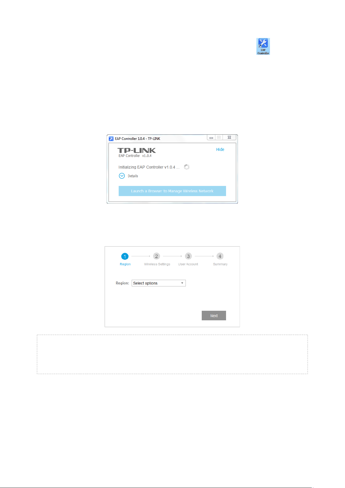
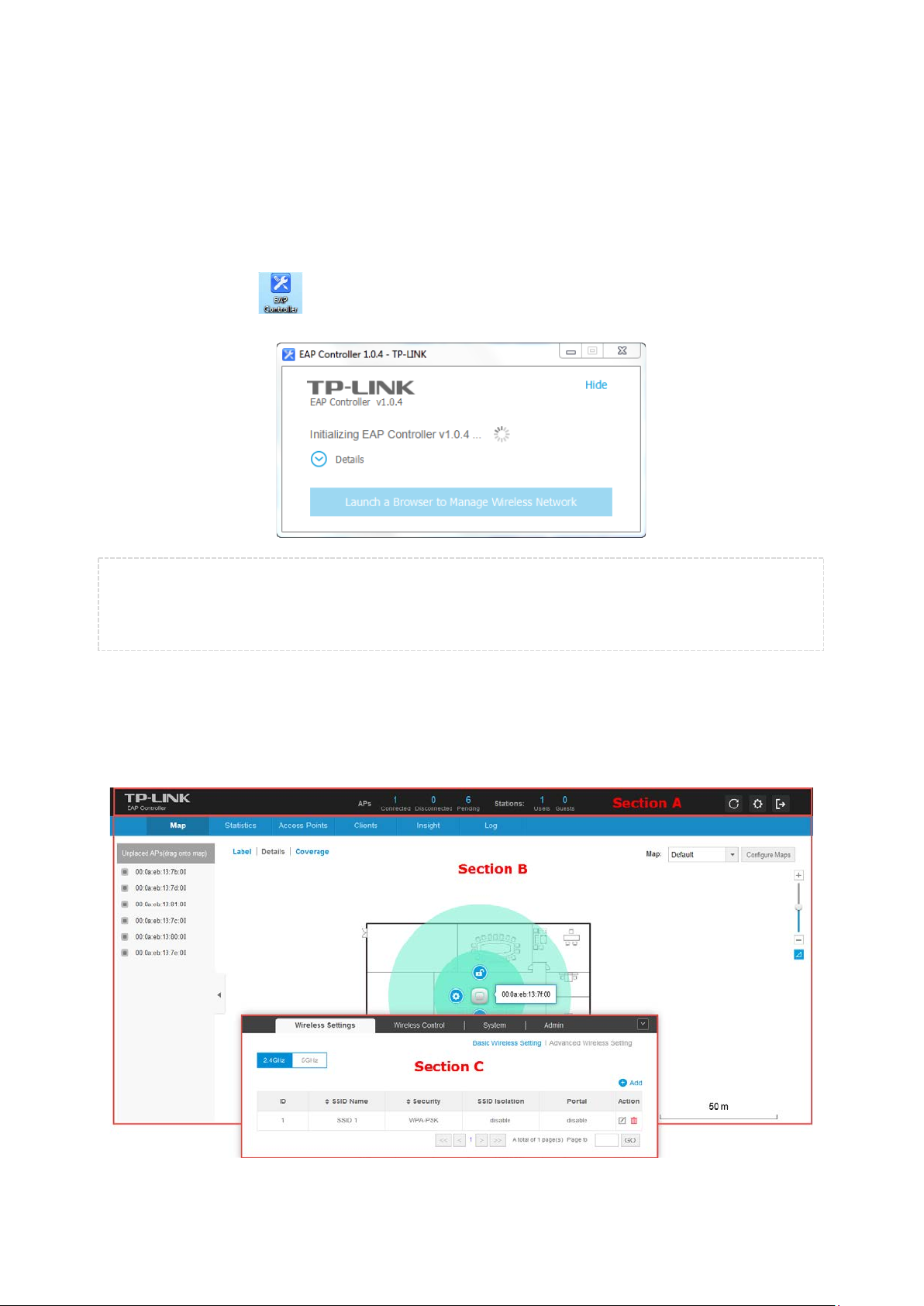
Step 1: Launch the EAP Controller on Controller Host and the following window will pop up. You can
click Hide to hide this window into the tray but DO NOT close it.
Step 2: After a while, your web browser will automatically open shown as the following screen. If it opens
but prompts a problem with this website’s security certificate, please continue to this website.
Select your country or region and click Next.
NOTE:
If your browser does not open, please click Launch a Browser to Manage Wireless Network.
Ensure that you select a correct Country/Region to comply with local laws.
4
Page 9
EAP Controller User Guide Chapter 1 System Setup
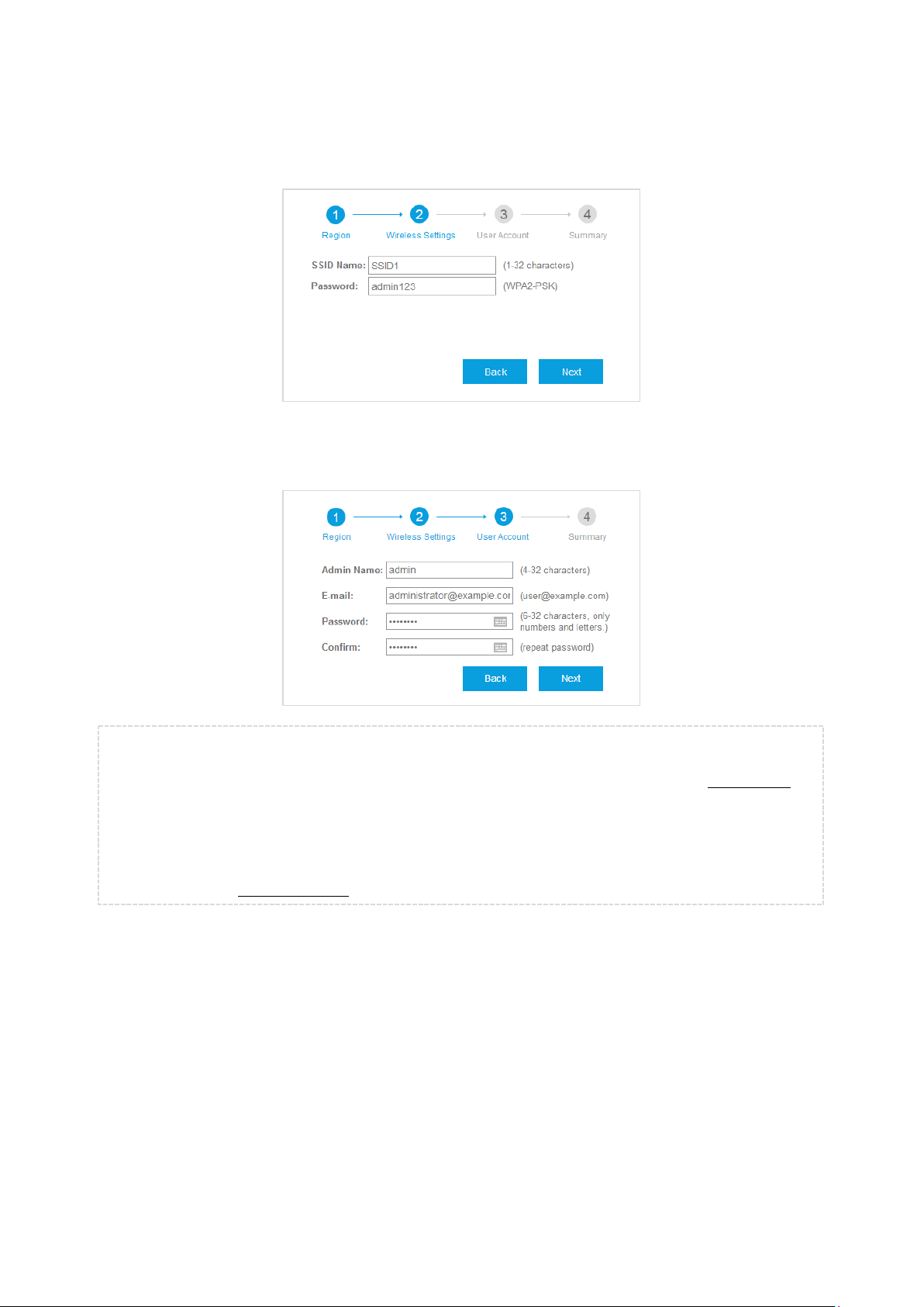
Step 3: Set an SSID name (wireless network name) and password. The EAP Controller will simultaneously
create two wireless networks, a 2.4GHz one and a 5GHz one both encrypted in the WPA2-PSK
mode. Click Next.
Step 4: Configure an admin name and password for login to the EAP Controller. Specify an email address
to receive the notification emails and reset your password if necessary. Click Next to continue.
NOTE:
Please remember well your password. After logging into the Controller, please set Mail Server on
the Controller Settings page so that you can reset the password if necessary.
The configured admin name and password will respectively serve as the username and password of
the adopted EAP devices for the first time. You can change the username and password of each EAP
device on the Device Account page.
5
Page 10

EAP Controller User Guide Chapter 1 System Setup
Step 5: Review your settings. Once the wizard is finished, the browser will be redirected to the
management interface.
Step 6: A login screen will appear for the EAP Controller management interface. Enter the admin name
and password you created and click Sign In. Then you will successfully log in the management
interface.
NOTE:
In addition to the Controller Host, other computers in the same LAN can also log into the management
interface to manage EAP devices. Before the login, the EAP Controller software must first keep running
on Controller Host. For example, when the IP address of the Controller Host is 192.168.0.100, enter
https://192.168.0.100:8043/login, or https://192.168.0.100:8043, or http://192.168.0.100:8088 in
the web browser for logging into the management interface.
6
Page 11
EAP Controller User Guide Chapter 2 Interface
Chapter 2 Interface
The EAP Controller software has a web-based interface for easy configuration and management.
To access the interface, perform the following steps:
Step 1: Double click from your windows desktop and the following screen will pop up.
NOTE:
Please do not close the EAP Controller window during configuring the EAP Controller and managing your
wireless network. Otherwise, the EAP devices cannot be managed.
Step 2: Your web browser will automatically open the EAP Controller login screen. Enter the admin name
and password you created and click Sign In.
Step 3: The EAP Controller’s management interface mainly divides into three sections as the following
screen.
7
Page 12
EAP Controller User Guide Chapter 2 Interface
Section A
Section A provides two common options: APs and Stations, accessible from all tabs on the EAP Controller
interface.
The APs option respectively displays the number of the EAPs that are connected, disconnected and
pending. You can click the number to go to the corresponding page on the Access Points Tab.
The Stations option separately displays the total number of users and guests. You can click the
number to go to the corresponding page on the Clients Tab.
On the right side of Section A, (Refresh), (Settings), and (Sign out) allow you to refresh the
current page, globally configure the wireless network, and sign out from the management interface.
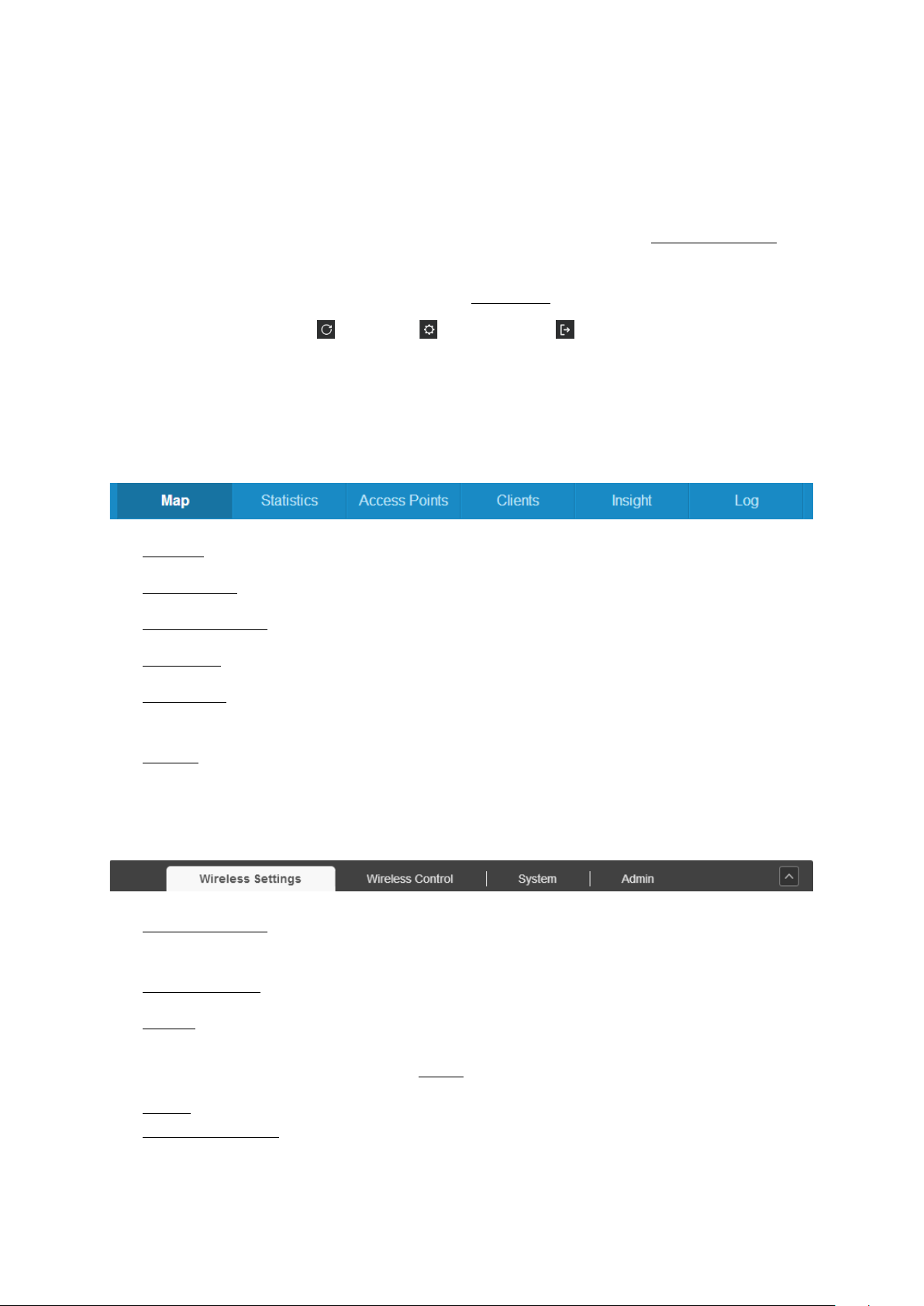
Section B
Section B divides into the monitor menu area (providing six monitor tabs) and the monitor display area
(where the detailed information under each tab displays).
Map Tab allows you to monitor the running condition of each EAP device.
Statistics Tab displays a visual representation of the network traffic of the managed EAPs.
Access Points Tab displays all the EAP devices on the local network for your management.
Clients Tab displays all the clients connected to the EAP wireless network.
Insight Tab displays the detailed information of all the previously connected clients and the
detected rogue APs.
Log Tab records the detailed information of the system logs for your troubleshooting.
Section C
Section C is the global setting area including four global setting pages.
Wireless Settings allows you to change the basic and advanced wireless setting. You can add the
2.4GHz or 5GHz wireless network and also configure their wireless parameters in details.
Wireless Control allows you to control the access of clients to your wireless networks.
System allows you to perform some configurations to the managed EAPs’ system, including Log
Setting, User Account, LED, Backup&Restore and Batch Upgrade. And you can also view the version
information of the EAP Controller on the About page.
Admin allows you to set permissions for the login accounts. You can also set mail server on the
Controller Settings page to reset your password.
8
Page 13
EAP Controller User Guide Chapter 3 Monitor
Chapter 3 Monitor
3.1 Map Tab
The EAP Controller software allows you to upload custom map images of your location(s) for a visual
representation of your wireless network. When you initially launch the EAP Controller application, a
default map is displayed. The legend at the bottom of the map shows the scale of the map.
The Map Tab can visually monitor the running condition and visual coverage range of each EAP device.
3.1.1 Add Custom Maps
The image formats that the EAP Controller software supports include .jpg, .gif, .png, .bmp and .tiff.
To upload a map to the EAP Controller, please perform the following steps:
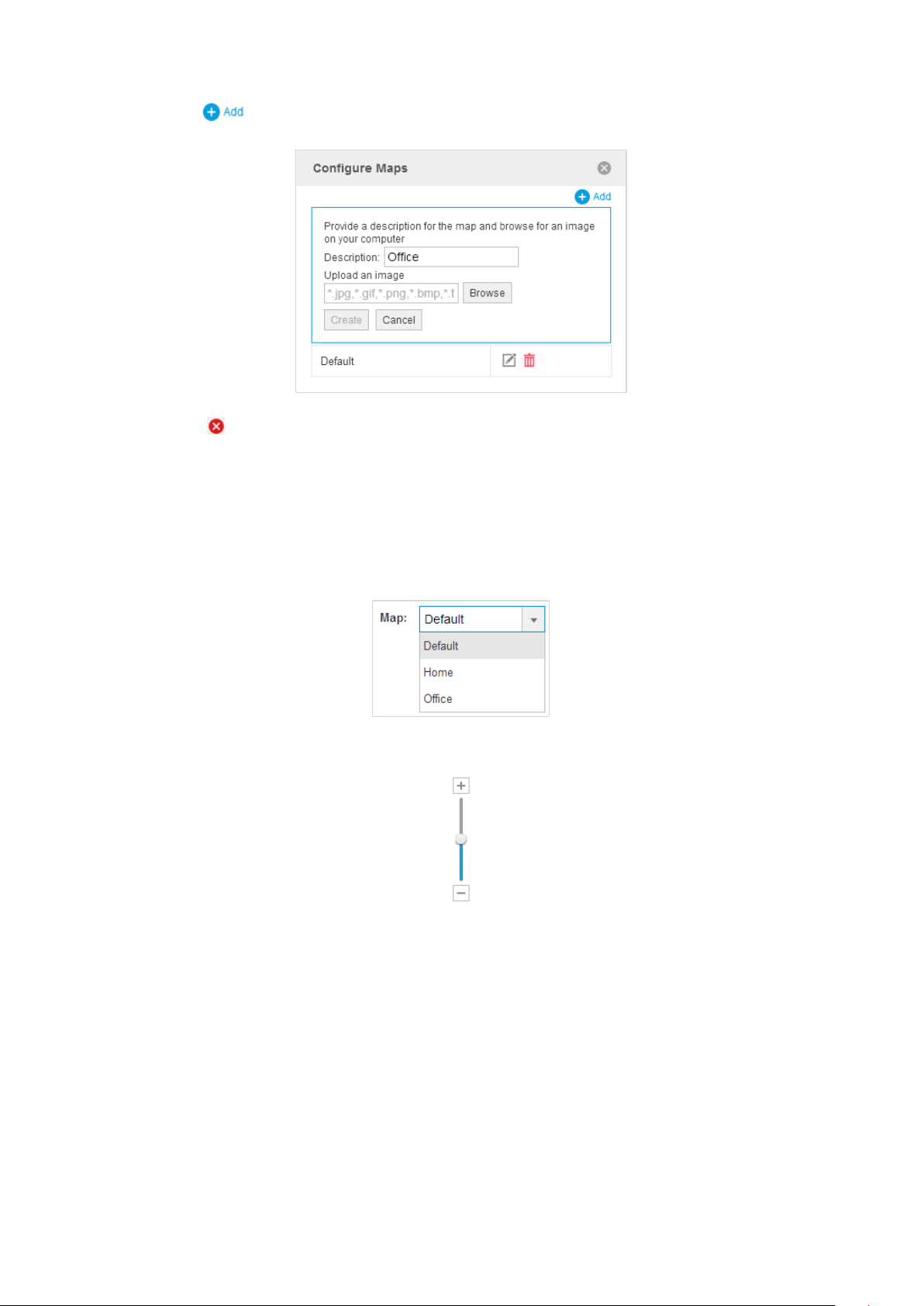
Step 1: Click Configure Maps on the upper right corner of map area to open the following window.
9
Page 14
EAP Controller User Guide Chapter 3 Monitor
Step 2: Click . Give a map description, select your customized map image, and click Create.
Step 3: Click to close the window.
3.1.2 Set the Map Scale
To set the map scale, perform the following steps:
Step 1: Select a map from the drop-down list.
Step 2: Use the zoom slider to zoom the map detail in and out.
10
Page 15
EAP Controller User Guide Chapter 3 Monitor
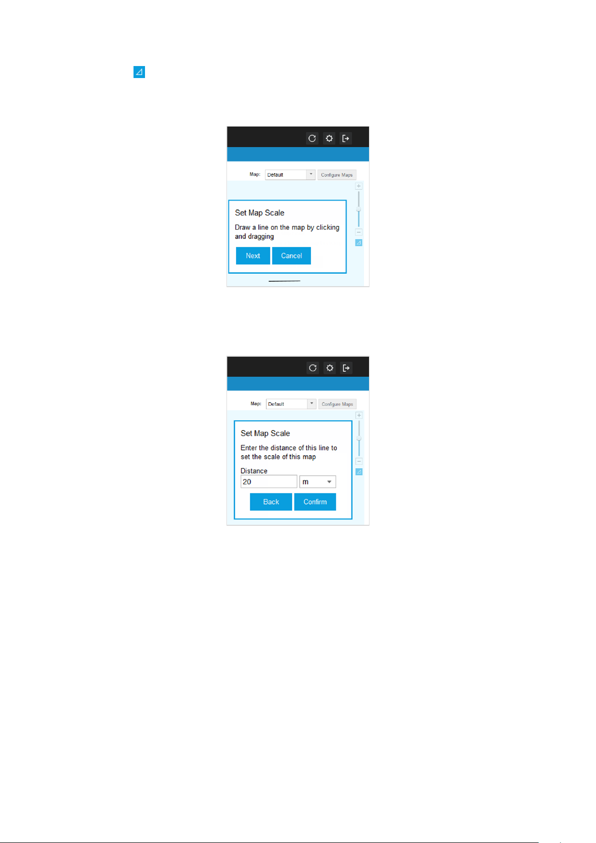
Step 3: Click . Then draw a line on the map by clicking and dragging the mouse. If you need to redraw
the line, just click and draw the mouse again to draw a new line. Once you are satisfied with the
line, click Next.
Step 4: Enter the distance that the line represents in the Distance field to set the scale of this map. The
distance is specified in meters by default but you can switch to feet using the drop-down
selection menu on the right. Click Confirm.
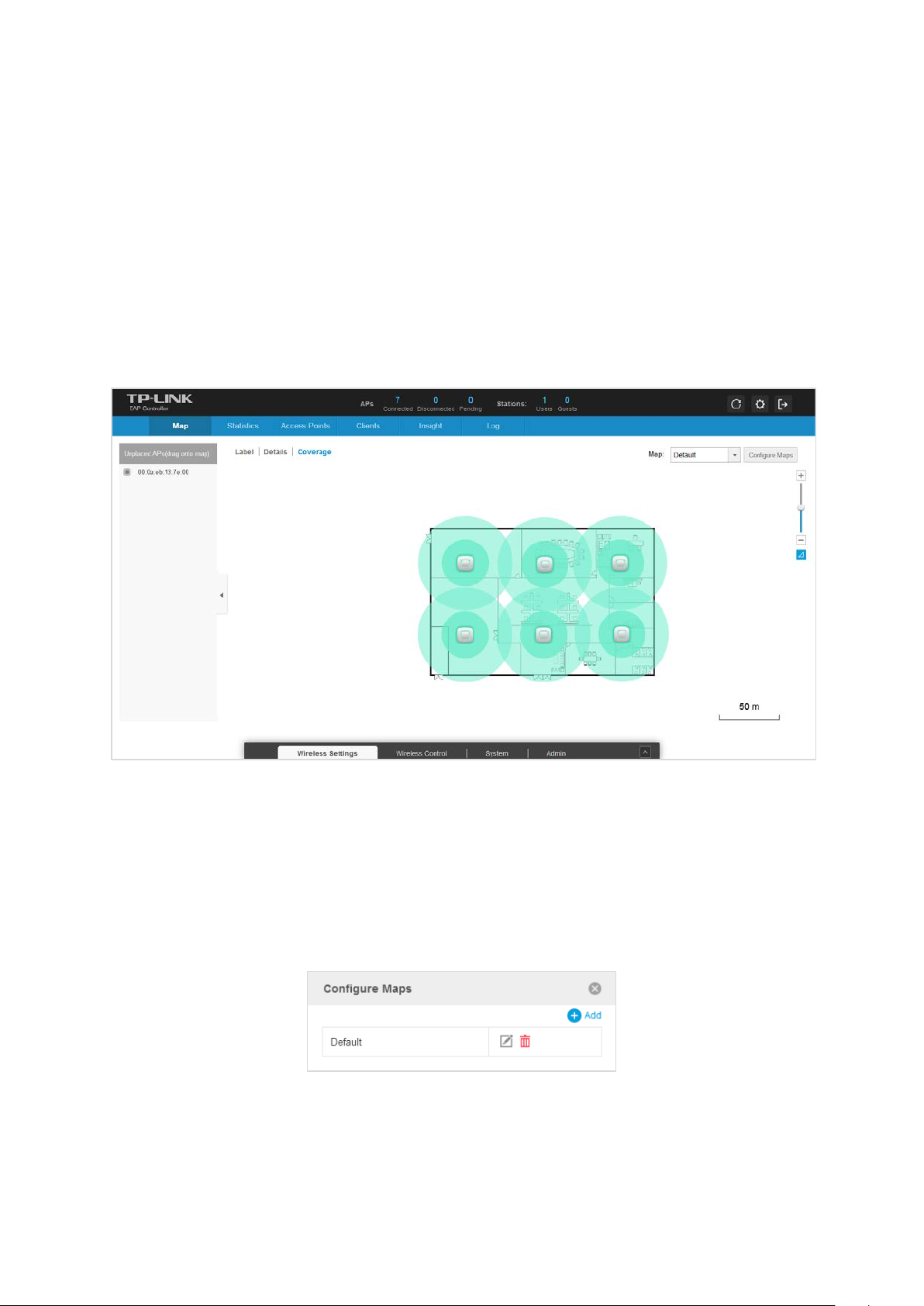
3.1.3 Place APs onto the Map
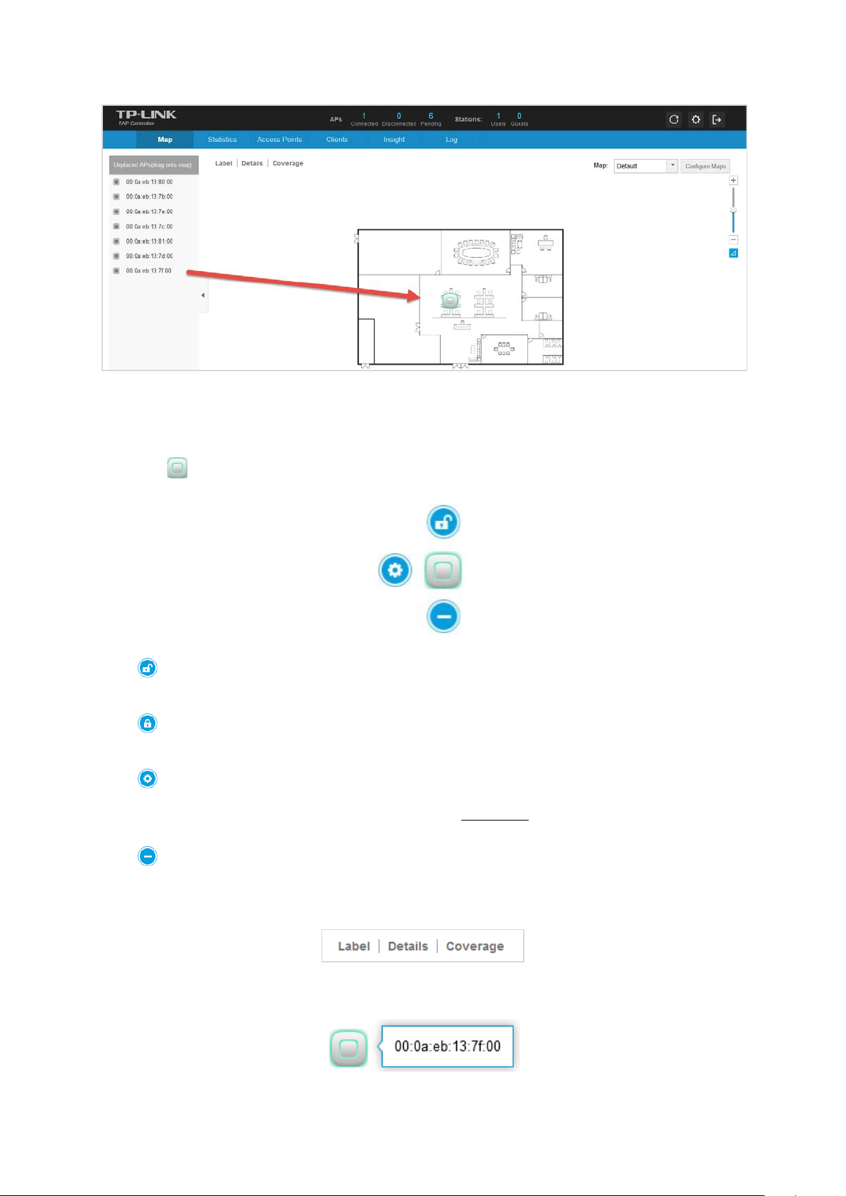
Place APs onto the Map
Drag the unplaced APs from the Unplaced APs list to the appropriate location on the map according to
its actual location.
11
Page 16
EAP Controller User Guide Chapter 3 Monitor
Reveal Additional Options
Click to reveal additional options.
Click to lock the selected EAP in the current location on the map.
Click to unlock the selected EAP and you can drag it to another location.
Click to display the Details window that allows you to view AP’s details and configure the wireless
parameters. For more detailed information, please refer to AP Details.
Click to remove the selected EAP from the map and it will back into the Unplaced APs list.
Click any of the following options to display EAP Label, Details, and Coverage on the map.
Click Label to only display EAP’s name. The default name is EAP’s MAC address.
12
Page 17
EAP Controller User Guide Chapter 3 Monitor
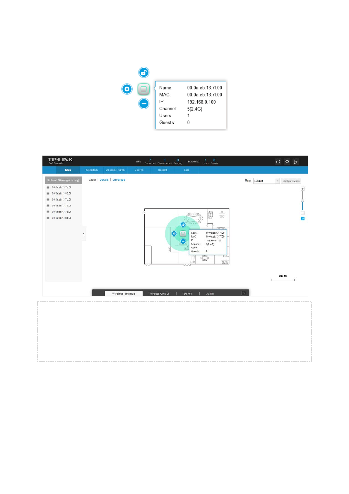
Click Details to display EAP’s name, MAC address, IP address, transmitting/receiving channel, number of
connected users, and number of connected guests.
Click Coverage to display a visual representation of the wireless range covered by EAPs.
NOTE:
The visual range covered by EAPs will appear only after you set the map scale. The visual coverage
has some differences from the actual situations.
The observer user cannot drag EAPs, upload/edit the map, or set the map scale, but can only view
the interface.
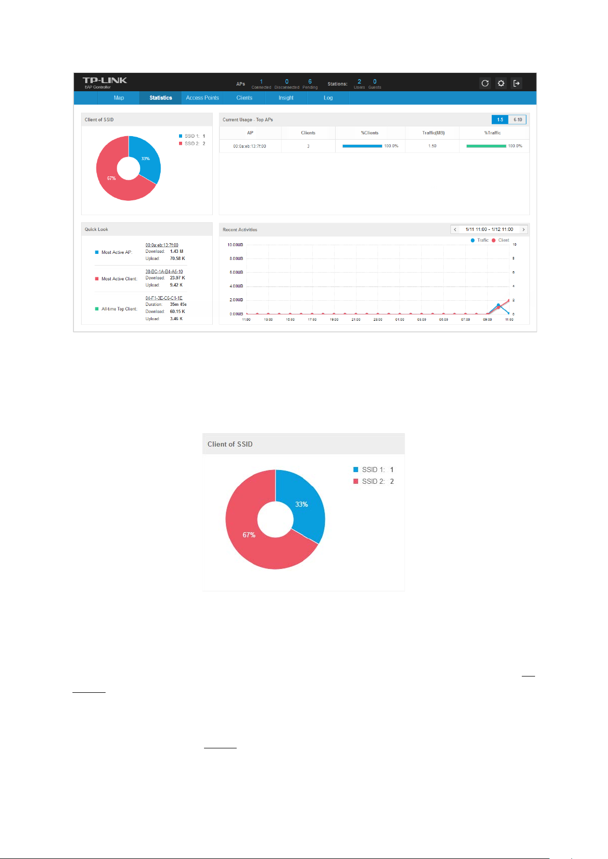
3.2 Statistics Tab
The Statistics tab provides a visual representation of the network traffic of your managed EAPs.
Charts represent the number and distribution of clients over each SSID. An hour-by-hour graph of the
usage over the specific 24 hours or one day-by-day graph of the usage over the specific 30 days is also
displayed on this screen.
13
Page 18
EAP Controller User Guide Chapter 3 Monitor
3.2.1 View the Client Distribution on SSID
A visual pie chart represents the client distribution on each SSID. For example, the SSID 2 has 2 clients,
which occupies 67% of all the clients.
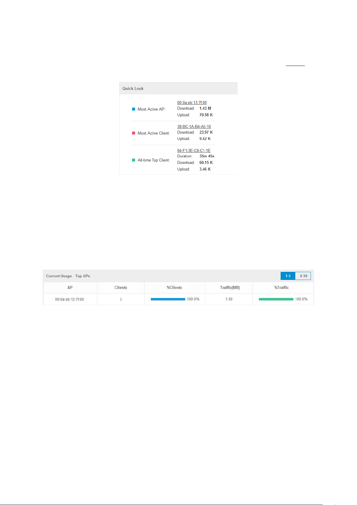
3.2.2 Quick Look
Most Active AP refers to the current connected AP with the maximum traffic. Its MAC address and total
amount of data downloaded/uploaded will be displayed. You can click the MAC address to open the AP
Details page.
Most Active Clients refer to the current connected client with the maximum traffic. Its MAC address and
total amount of data downloaded/uploaded will be displayed. You can click the MAC address to open the
connection history page. See Clients for additional information.
14
Page 19
EAP Controller User Guide Chapter 3 Monitor
All-Time Top Client refers to the client with the maximum traffic among all the clients that have accessed
the EAP network before. Its MAC address, duration and total amount of data downloaded/uploaded will
be displayed. You can click the MAC address of to open the connection history page. See Clients for
additional information.
3.2.3 View Current Usage-Top APs
This tab displays the hostname, connected client amount and traffic of ten APs with the top current
usage. %Clients indicates the proportion of current connected clients to the Top APs’ acceptable client
capacity. %Traffic indicates the proportion of the AP’s current data transmission amount to the Top APs’
total transmission amount. The AP’s transmission amount equals the sum of the transmission traffic of all
the current clients that connect to the AP. Its maximum transmission capacity depends on its radio
configuration.
3.2.4 View Recent Activities
The Recent Activities statistics can be toggled between a view for the past specific 24 hours and one for
the past specific 30 days. The left ordinate axis indicates the traffic and the right ordinate axis represents
the number of the clients. The bottom abscissa axis shows the selected time period. Traffic indicates a
visual graph of the network traffic during the selected time period. Client indicates a visual graph of the
number of the connected clients during the selected time period. For example, the statistics information
at 8:00 indicates the traffic size and client number from 7:00 to 8:00.
15
Page 20

EAP Controller User Guide Chapter 3 Monitor
At the top right of the screen, you can filter the statistics by date and time period. You can also change
the duration interval by toggling between 24h (24 hours) and 30d (30 days). The statistics information of
Traffic and Client will never be cleared.
3.3 Access Points Tab
The EAP Controller software can detect all the EAP devices in the LAN and list them on the Access Points
page. The clickable list displays the EAP’s name/MAC address, IP address, status, model, software version,
number of connected clients and download/upload bytes.
According to their connection status, all the EAP devices are divided into three categories: Connected,
Disconnected and Pending.
Only after you adopt a pending EAP, it can be connected and managed. If a connected EAP powers off, it
will be disconnected. If you reset or forget a connected/disconnected EAP, it will change into a pending
one again. The following orderly introduces three statuses of an EAP from Pending to Disconnected.
Pending displays that the EAP is in the default state and available for adoption. You can locate and
adopt pending EAPs. Only after they are adopted and connected, you can upgrade them. When EAPs
are connected and managed by the EAP Controller, you cannot log into their own web interface until
you Forget this AP.
16
Page 21

EAP Controller User Guide Chapter 3 Monitor
In the Action column, select an icon to execute the corresponding operation:
Click to locate the AP on the map. It will redirect to the Map tab. If the AP is not on the map but in
the Unplaced APs list, it will be highlighted in red.
Click to adopt the pending APs and the following window will pop up. Enter the username and
password and click Apply. After adopted at the first time, this AP’s username and password are separately
the admin name and password that you configured at Quick Setup. And you can change them on the
Device Account page.
On the condition that there are many EAPs to be adopted, you can click to achieve the
batch adoption for these EAPs.
Connected displays that the EAP is being managed. After you adopt it, the Status will be Provisioning
until the AP is connected. Connected AP can be located, reboot and upgraded. A connected EAP will
turn into a pending one only after you Forget this AP.
In the Action column, select an icon to execute the corresponding operation:
Click to reboot the connected APs.
17
Page 22

EAP Controller User Guide Chapter 3 Monitor
Click to upgrade the connected APs and the following window will pop up. Click Browse to locate
and choose the upgrade file in your computer, then click Upgrade to install the latest EAP firmware. The
Status will appear as Upgrading until the process is complete and the EAP reconnects to the EAP Controller
software. You can upgrade the EAP devices in batches on the Batch Upgrade page.
Disconnected displays that the EAP is unreachable by the EAP Controller software. Disconnected
EAP can only be located the position on the map. When a disconnected EAP is reset to factory default
settings or you forget it, it will turn into a pending one.
3.4 Clients Tab
The Clients tab displays a list of users and guests that connect to the EAP network. The clients are divided
into two types: User and Guest. The client connecting to the EAP wireless network without the Portal
authentication is User while the client connecting to the wireless network with the Portal authentication
is Guest.
The Clients tab displays the client’s MAC address, connected AP and connected SSID, the level (User or
Guest), download/upload bytes, active time and signal strength.
If the client is Guest, you can click in the Action column to cancel the authorization for it.
MAC Address column, click the MAC address to get the client’s connection history. This connection
In the
history window displays the connection date/time, duration and the client’s download/upload bytes.
18
Page 23

EAP Controller User Guide Chapter 3 Monitor
3.5 Insight Tab
The Insight tab displays a list of clients that have connected to the EAPs network during the specified
period. Clients Statistics tab and Untrusted/Trusted Rogue APs tab will be introduced separately.
3.5.1 Clients Statistics
The Clients Statistics page displays all the previously connected clients and their MAC address,
download/upload bytes, duration and the time of last seen. You click the MAC address to get its
connection history.
3.5.2 Untrusted Rogue APs
A Rogue AP is an access point that has been installed on a secure network without explicit authorization
from a system administrator.
The EAP Controller can scan all channels to detect all APs in the vicinity of the network. During the
detection, clients will disconnect with EAPs. If rogue APs are detected, they will be shown on the
Untrusted Rogue APs list.
The Untrusted Rogue APs page displays the untrusted rogue APs’ MAC address, SSID, band, channel,
security mode, total number of Beacon, signal strength and the time of last seen. If you want to move an
untrusted rogue AP to the Trusted Rogue AP list, click in the Action column.
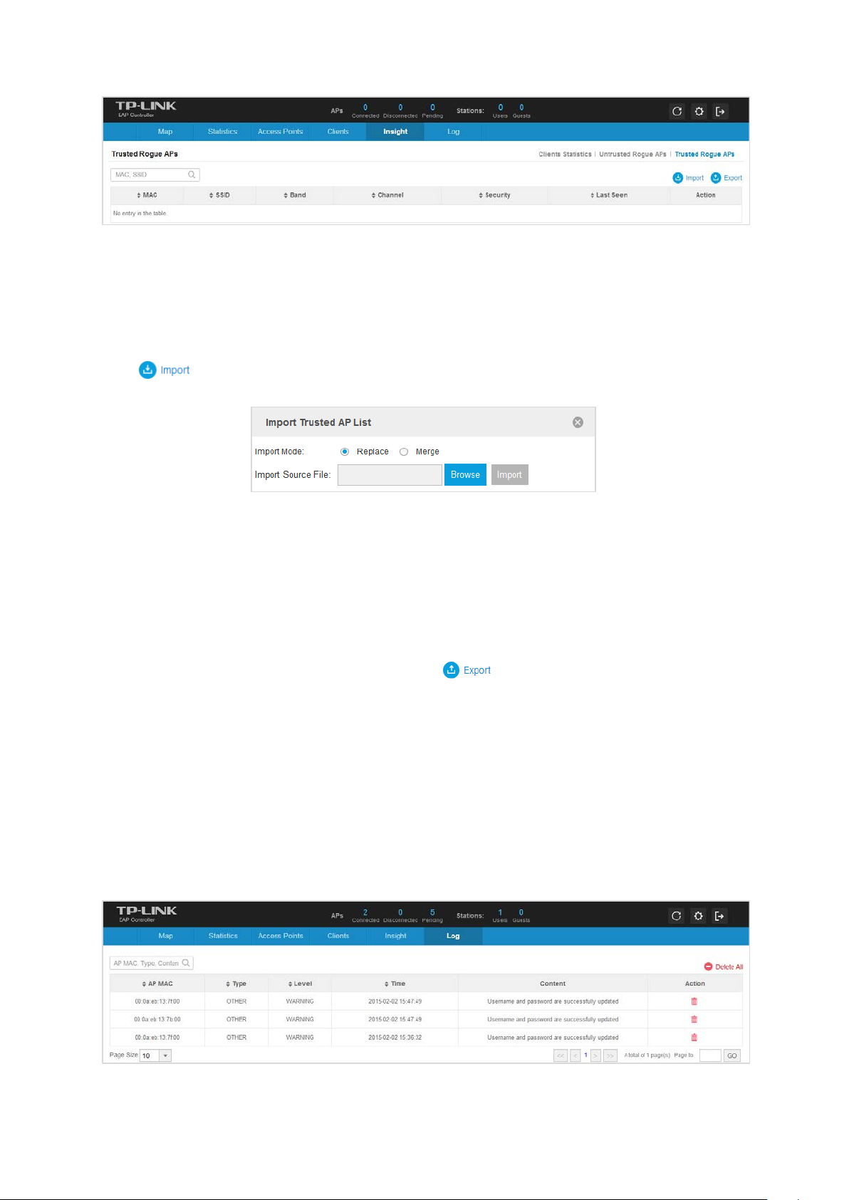
3.5.3 Trusted Rogue APs
The Trusted Rogue APs page displays the trusted rogue APs’ MAC address, SSID, band, channel, security
mode and the time of last seen. If you want to move a trusted rogue AP to the Untrusted Rogue AP list,
click in the Action column.
19
Page 24
EAP Controller User Guide Chapter 3 Monitor
Import/Export Trusted AP List
You can import a list of trusted APs, a saved list acquired from another AP or created from a text file. If the
MAC address of an AP appears in the Trusted AP List, it will not be detected as a rogue.
Click to import the trusted AP list and the following window will pop up.
Select an import mode:
Replace: Select to import the list and replace the contents of the current Trusted AP List.
Merge: Select to import the list and add the APs in the imported file to the APs currently shown in
the Trusted AP List.
Click Browse to locate the imported file and choose it. Then click Import to import the Trusted AP List.
You can also export a list and save it in your PC. Click to export and download the trusted AP
list.
3.6 Log Tab
The logs of the EAP Controller can effectively record, classify and manage the system information of the
managed EAPs, providing powerful support for network administrator to monitor network operation and
diagnose malfunctions.
The Log tab displays AP’s MAC address, log type, level, occurred time and content.
20
Page 25

EAP Controller User Guide Chapter 4 Global Setting
Chapter 4 Global Setting
This chapter consists of four configuration subpages: Wireless Settings, Wireless Control, System and
Admin. The configurations on the first three subpages will be applied to all the EAPs in the LAN. While
Admin is used to configure the user account for login to the EAP Controller.
4.1 Wireless Settings
Wireless Settings page allows you to add wireless networks and configure wireless parameters. Please
carefully read the details before configuring your networks.
4.1.1 Basic Wireless Setting
The Basic Wireless Settings page allows you to add and edit wireless networks.
Add Wireless Netwok
Step 1: Click to add a 2.4GHz/5GHz wireless network. The following window will pop up.
21
Page 26

EAP Controller User Guide Chapter 4 Global Setting
Step 2: Specify the SSID name and wireless VLAN ID. Select whether to broadcast this SSID and whether
to enable the Portal authentication. If the Portal authentication is enabled, you can configure it
on the Portal page. Select whether to enable the SSID Isolation feature. Enabling this feature
means that all the clients connecting to this added wireless network cannot communicate with
each other.
Step 3: Select the security mode of the wireless network.
Three security modes are provided: WEP (Wired Equivalent Privacy), WPA-Enterprise, and WPA-PSK
( W PA P r e -Shared Key). (WPA stands for Wi-Fi Protected Access, a security standard compatible with IEEE
802.11e. Enterprise refers to using Radius Server for authentication, while Radius stands for Remote
Authentication Dial-In User Service.) Settings vary in different modes as the details are in the following
introduction. If you select None, any client can be allowed to access the wireless network.
WEP: Based on the IEEE 802.11 standard, this security mode is less safe than WPA -Enterprise and
WPA-PSK.
NOTE:
WEP is not supported in 802.11n mode. If WEP is applied in 802.11n mode, the clients may not be able to
access the wireless network. If WEP is applied in 11b/g/n mode (2.4GHz) or 11a/n (5GHz), the EAP device
may work at a low transmission rate.
Typ e: Select the authentication type of WEP.
Auto: The default setting is Auto, which can select Open System or Shared Key automatically based
on the wireless client's capability and request.
Open System: After you select Open System, client in the wireless network can pass the
authentication and associate with the wireless network without password. However, correct
password is necessary for data transmission.
Shared Key: After Shared Key is selected, you have to enter password for client to pass the
authentication, or it cannot associate with the wireless network or transmit data.
Key Selected: You can configure four keys in advance and select one as the present valid key.
WEP Key Format: Select the WEP key format ASCII or Hexadecimal.
ASCII: ASCII format stands for any combination of keyboard characters in the specified length.
22
Page 27
EAP Controller User Guide Chapter 4 Global Setting
Hexadecimal: Hexadecimal format stands for any combination of hexadecimal digits (0-9, a-f, A-F)
in the specified length.
Key Type: Select the WEP key length (64-Bit, 128-Bit, or 152-Bit) for encryption.
64Bit - Enter 10 hexadecimal digits or 5 ASCII characters.
128Bit - Enter 26 hexadecimal digits or 13 ASCII characters.
152Bit - Enter 32 hexadecimal digits or 16 ASCII characters.
Key Value: Enter the WEP keys. The length and valid characters are affected by key type.
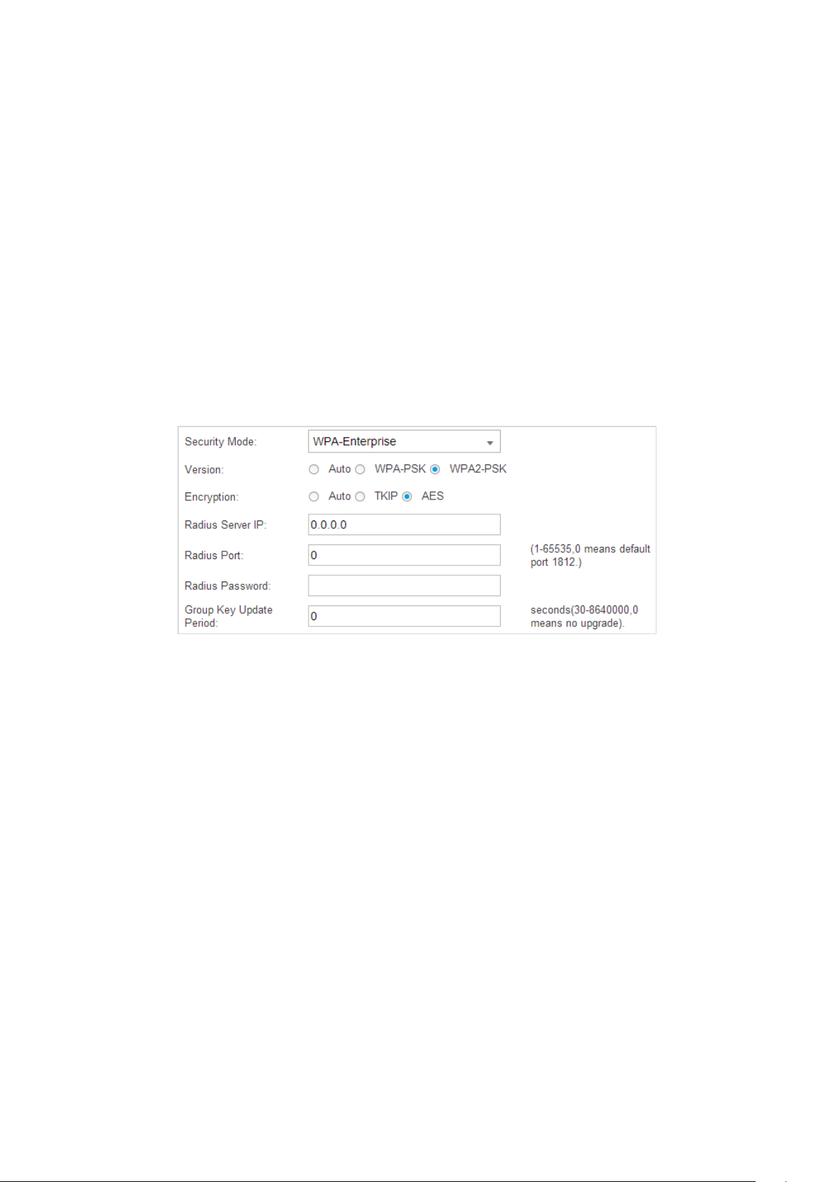
WPA-Enterprise:
different users and it is much safer than WPA-PSK. WPA-Enterprise with Radius is an implementation
of the Wi-Fi Alliance IEEE 802.1i standard, which includes AES and TKIP mechanisms. Encryption type
TKIP is not supported in the 802.11n mode. At present, WPA has two versions: WPA and WPA2.
Version: Select the version of WPA-Enterprise.
Auto: Select WPA or WPA2 automatically based on the wireless client's capability and request.
WPA-PSK: Pre-shared key of WPA .
Based on Radius Server, WPA-Enterprise can assign different passwords for
WAP2-PSK: Pre-shared key of WPA2.
Encryption: Select the Encryption type, including Auto, TKIP, and AES. The default setting is Auto, which
can select TKIP (Temporal Key Integrity Protocol) or AES (Advanced Encryption Standard) automatically
based on the wireless client's capability and request. AES is more secure than TKIP that is not supported
in 802.11n mode. We recommend you select AES as the encryption type.
Radius Server IP/Port: Enter the IP address/port of the Radius S erver.
Radius Password: Set the shared secret of the Radius Server.
Group Key Update Period: Specify the group key update period in seconds.
23
Page 28

EAP Controller User Guide Chapter 4 Global Setting
WPA-PSK: Based on pre-shared key, it is characterized by higher safety and simple settings, which
suits for common households and small business. WPA-PSK has two versions: WPA-PSK and WPA2-
PSK.
Please refer to WPA-Enterprise to configure Version, Encryption, and Group Key Update Period. Set
your wireless password in the Wireless Password field.
Step 4: Click Apply to successfully add the wireless network into the list.
4.1.2 Advanced Wireless Setting
On the Advanced Wireless Setting page, you can configure Beacon Interval, DTIM Period, RTS Threshold
and Fragmentation Threshold.
Beacon Interval: Beacons are transmitted periodically by the EAP device to announce the presence of a
wireless network for the clients. Beacon Interval value determines the time interval of the beacons sent
by the device. You can specify a value from 40 to 100. The default value is 100.
24
Page 29

EAP Controller User Guide Chapter 4 Global Setting
DTIM Period: This value indicates the number of beacon intervals between successive Delivery Traffic
Indication Messages (DTIMs) and this number is included in each Beacon frame. A DTIM is contained in
Beacon frames to indicate whether the access point has buffered broadcast and/or multicast data for the
client devices. Following a Beacon frame containing a DTIM, the access point will release the buffered
broadcast and/or multicast data, if any exists. You can specify the value between 1-255 Beacon Intervals.
The default value is 1, indicating the DTIM Interval is the same as Beacon Interval. An excessive DTIM
interval may reduce the performance of multicast applications. We recommend you keep it by default.
RTS Threshold: When the RTS Threshold is activated, all the clients and EAPs follow RTS (Request to Send)
protocol. If the client is to send packets, it will send a RTS packet to EAP to inform that it will send data.
After receiving the RTS packet, the EAP notices other clients in the same wireless network to delay their
transmitting of data. At the same time, the EAP informs the requesting client to send data. The default is
2347. If you specify a low threshold value, RTS packets are sent more frequently, which consumes more
bandwidth and reduces the throughput of the packet.
Fragmentation Threshold: Specify the fragmentation threshold for packets. If the size of packet is larger
than the fragmentation threshold, the packet will be fragmented into several packets. Too low
fragmentation threshold may result in poor wireless performance caused by the excessive packets. The
recommended and default value is 2346 bytes.
4.2 Wireless Control
4.2.1 Portal
Portal authentication enhances the network security by providing authentication service to the clients
that want to access the wireless local network. The clients have to log into a web page to establish
verification, after which the clients will be guests.
Before passing the portal authentication, different clients can get different network resources through
setting authentication policy. Part of network resources can be accessed by the specific unauthorized
clients, who can access other unspecific resources only after authorized. What’s more, you can customize
the authentication login page and specify a URL which the newly authenticated clients will be redirected
to. Please refer to Configure Portal or Free Authentication Policy according to your needs.
NOTE:
To apply Portal on a wireless network, please go to Wireless Settings→Basic Setting to enable Portal of
a selected SSID.
Configure Portal
Three different types of authentication methods are available: No Authentication, Local Password and
External Radius Server. Please refer to the following contents to configure Portal according to your
needs.
25
Page 30

EAP Controller User Guide Chapter 4 Global Setting
No Authentication
When this option is selected, clients just need to accept the term of use.
Authentication Type: Select No Authentication.
Authentication Timeout: Specify a designated period of time for client’s access to the Internet. Options
include: 1 Hour, 8 Hours, 24 Hours, 7 Days, and Custom. Custom allows users to define the time in days,
hours, and minutes. By default authentication timeout is one hour. If a timeout occurs, the client will
disconnect with the Internet.
Redirect: Disabled by default. Check the box to enable Redirect if you hope that the portal redirects the
newly authenticated clients to the configured URL.
Redirect URL: Enter the URL that a newly authenticated client will be redirected to.
Portal Customization: Select Local Web Portal. The authentication login page will be provided by the
built-in portal server. Configure the title and terms of the authentication login page.
26
Page 31
EAP Controller User Guide Chapter 4 Global Setting
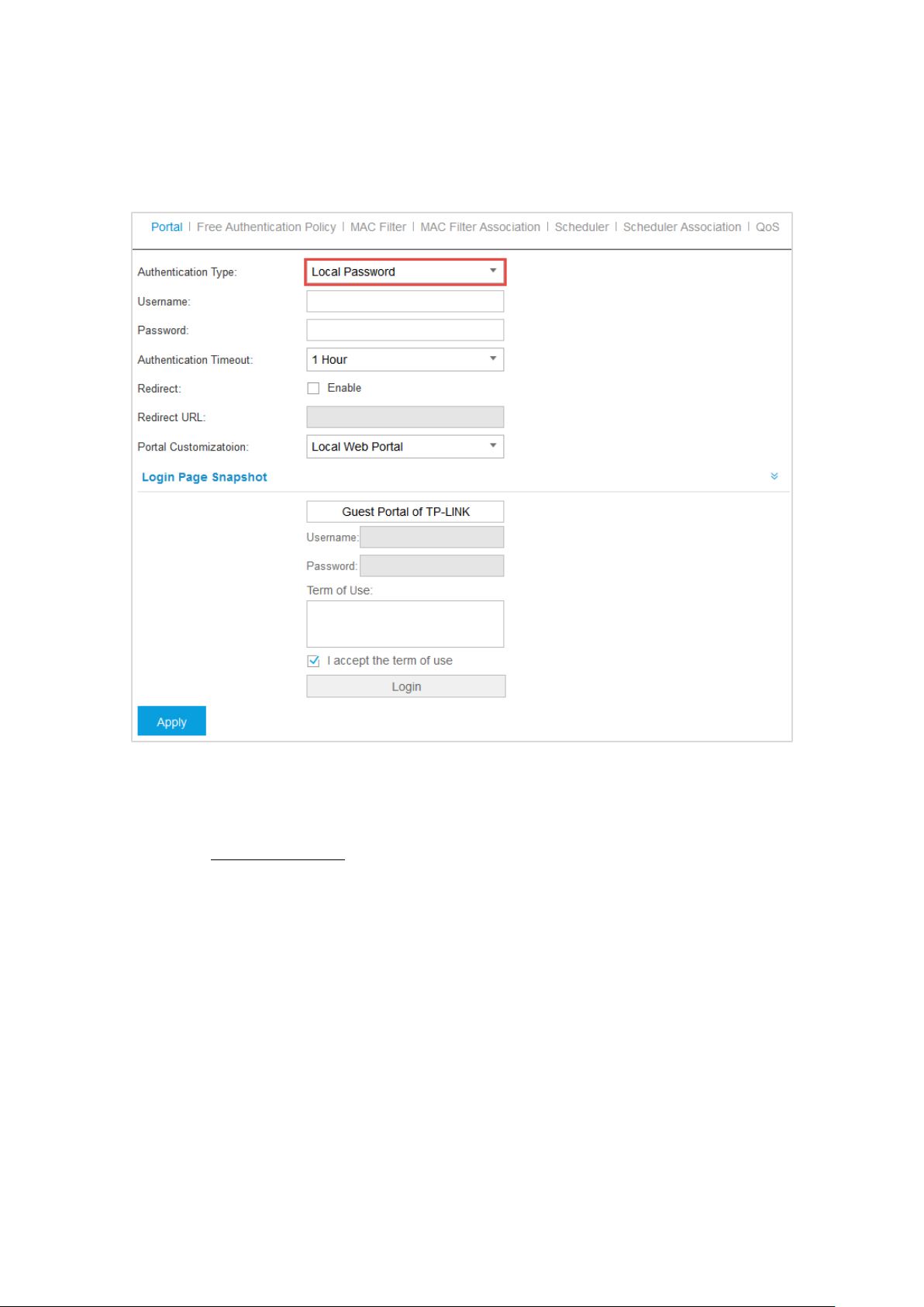
Local Password
When this option is selected, clients are required to enter the local username and password and accept
the term of use.
Authentication Type: Select Local Password.
Username/Password: Specify the username/password for local authentication.
Please refer to No Authentication to configure Authentication Timeout, Redirect, Redirect URL, and
Portal Customization.
27
Page 32

EAP Controller User Guide Chapter 4 Global Setting
External Radius Server
If you have a Radius Server, select External Radius Server and you can get two types of portal
customization: Local Web Portal and External Web Portal. The authentication login page of Local Web
Portal is provided by the built-in portal server of the EAP. The External Web Portal is provided by external
portal server.
Authentication Type: Select External Radius Server.
28
Page 33

EAP Controller User Guide Chapter 4 Global Setting
Radius Server IP/Port: Enter the IP address/port of Radius Server.
Radius Password: Specify the password of Radius Server.
Portal Customization:
Local Web Portal
Configure the Login Page Snapshot.
External Web Portal
When External Radius Server is configured and External Web Portal is selected, you also need to put
the external web portal server to a whitelist of Free Authentication Policy, otherwise clients cannot
access it before authenticated. Enter the authentication login page’s URL provided by the remote portal
server.
Please refer to No Authentication to configure Authentication Timeout, Redirect, and Redirect URL.
4.2.2 Free Authentication Policy
Free Authentication Policy allows some specified clients to access specific network resources without
authentication. On the Free Authentication Policy tab, you can add and view free authentication policy.
Add Free Authentication Policy
Step 1: Click to add a new authentication policy and configure its parameters.
29
Page 34

EAP Controller User Guide Chapter 4 Global Setting
Step 2: Specify the policy name. And set either Source IP Range with the subnet/mask of the clients or
Source MAC. Then set the Destination IP Range with the destination IP address and subnet mask
for free authentication policy. Assign the service port as the Destination Port. Check the Status
box to enable the policy.
NOTE:
When External Radius Server is configured and External Web Portal is selected, please set the IP address
and subnet mask of your external web portal server as the Destination IP Range. Otherwise, clients cannot
access it before authenticated
Step 3: Click Apply and the policy is successfully added as the following screen.
4.2.3 MAC Filter
MAC filter can be used to allow or exclude the listed clients to authenticate with the access point. Thereby
it can effectively control client’s access to the wireless network.
Add MAC Filter Group
Step 1: Click and specify a name for the group.
30
Page 35

EAP Controller User Guide Chapter 4 Global Setting
Click Apply and the MAC Filter group will be successfully added as the following screen.
Step 2: Click and specify a MAC Filter address.
Click Apply and the MAC address you specified will be successfully added as the following screen.
4.2.4 MAC Filter Association
You can associate the added MAC Filter group with SSID.
Check the Enable MAC Filtering box and click Apply to enable the MAC Filtering feature. In the MAC
Filter Name column, select a MAC Group from the drop-down list and allow or deny its members to
access the wireless network. Click Apply to enforce this MAC Filter Association entry in the Setting
column.
31
Page 36

EAP Controller User Guide Chapter 4 Global Setting
4.2.5 Scheduler
Scheduler allows you to configure rules with specific time interval for EAPs, which automates the enabling
or disabling of the EAP or radio. When Associated with SSID is selected, you can configure rules for a
certain radio. When Associated with AP is selected, you can configure rules for an EAP device.
One way you can use this feature is to schedule the radio to operate only during the office working time
in order to achieve security and reduce power consumption. You can also use the Scheduler to allow
access to EAPs for wireless clients only during the specific time in the day.
Add Scheduler Profile
Step 1: Click and specify a name for the profile rule.
Click Apply and the profile is added in the list and the following screen will be shown.
32
Page 37

EAP Controller User Guide Chapter 4 Global Setting
Step 2: Click to add a profile item.
Select the day mode and Custom allows you to choose the desired days, such as Mon and Fri. If you select
all day-24 hours, Start Time or End Time cannot be specified.
Click Apply and the profile item is successfully added in the list.
4.2.6 Scheduler Association
You can associate the profile item you added with SSID/AP.
Check the Scheduler box to enable the Scheduler feature, select Associated with SSID/AP and click
Apply to enable your association.
33
Page 38

EAP Controller User Guide Chapter 4 Global Setting
The list entries will be different according to your selection of association mode.
Associated with SSID
In the Profile Name column, select a profile name from the drop-down list. Select Radio On/Off to turn
on/off the wireless network during the time interval set for the profile. Click Apply to enforce this
Scheduler Association entry in the Setting column.
Associated with AP
In the Profile Name column, select a profile name from the drop-down list. Select Radio On/Off to turn
on/off all the wireless network on the selected Access Point during the time interval set for the profile.
Click Apply to enforce this Scheduler Association entry in the Setting column.
4.2.7 QoS
The EAP Controller software allows you to configure the quality of service (QoS) on the EAP device for
optimized throughput and better performance when handling differentiated wireless traffic, such as
Voice-over-IP (VoIP), other types of audio, video, streaming media, and traditional IP data.
To configure QoS on the EAP device, you should set parameters on the transmission queues for different
types of wireless traffic and specify minimum and maximum wait times (through contention windows)
for transmission.
In normal use, the default values for the EAP device and station EDCA (Enhanced Distributed Channel
Access) should not be changed. Changing these values affects the QoS provided.
34
Page 39

EAP Controller User Guide Chapter 4 Global Setting
Restore to Default Values: Click Restore to restore all the QoS parameters to factory default settings.
Wi-Fi Multimedia (WMM): By default enabled. With WMM enabled, the EAP devices have the QoS
function to guarantee the transmission of audio and video packets with high priority. Disenabling WMM
is not allowed if you set the 802.11n only or 802.11b/g/n mixed mode on the EAPs. If WMM is disenabled,
you cannot set the 802.11n only or 802.11b/g/n mixed mode on the EAPs.
NoAcknowledgement: Select Enable to specify that the EAP devices should not acknowledge frames
with QosNoAck as the service class value.
Unscheduled Automatic Power Save Delivery: By default enabled. A power management method,
APSD is recommended if VoIP phones access the network through the EAP device.
AP EDCA Parameters
AP EDCA parameters affect traffic flowing from the EAP device to the client station.
35
Page 40

EAP Controller User Guide Chapter 4 Global Setting
Queue displays the transmission queue: Data 0>Data 1>Data 2>Data 3.
Data 0 ( Voice)—High priority queue, minimum delay. Time-sensitive data such as VoIP and streaming
media are automatically sent to this queue.
Data 1 (Video)—High priority queue, minimum delay. Time-sensitive video data is automatically sent
to this queue.
Data 2 (Best Effort)—Medium priority queue, medium throughput and delay. Most traditional IP data
is sent to this queue.
Data 3 (Background)—Lowest priority queue, high throughput. Bulk data that requires maximum
throughput and is not time-sensitive is sent to this queue (FTP data, for example).
Arbitration Inter-Frame Space: A wait time for data frames. The wait time is measured in slots. Valid
values for AIFS are from 0 to 15.
Minimum Contention Window: A list to the algorithm that determines the initial random backoff wait
time (window) for retry of a transmission. This value must be lower than or equal to the value for the
Maximum Contention Window.
Maximum Contention Window: The upper limit (in milliseconds) for the doubling of the random backoff
value. This doubling continues until either the data frame is sent or the Maximum Contention Window
size is reached.
Maximum Burst: An EAP EDCA parameter that applies only to traffic flowing from the EAP to the client
station. This value specifies (in milliseconds) the maximum burst length allowed for packet bursts on the
wireless network. A packet burst is a collection of multiple frames transmitted without header
information. The decreased overhead results in higher throughput and better performance. The valid
values are multiples of 32 between 0 and 8192.
Station EDCA Parameters
Station EDCA parameters affect traffic flowing from the client station to the EAP device.
TXOP Limit: The TXOP Limit is a station EDCA parameter and only applies to traffic flowing from the client
station to the EAP device. The Transmission Opportunity (TXOP) is an interval of time, in milliseconds,
when a WME client station has the right to initiate transmissions onto the wireless medium (WM) towards
the EAP device. The valid values are multiples of 32 between 0 and 8192.
36
Page 41
EAP Controller User Guide Chapter 4 Global Setting
4.3 System
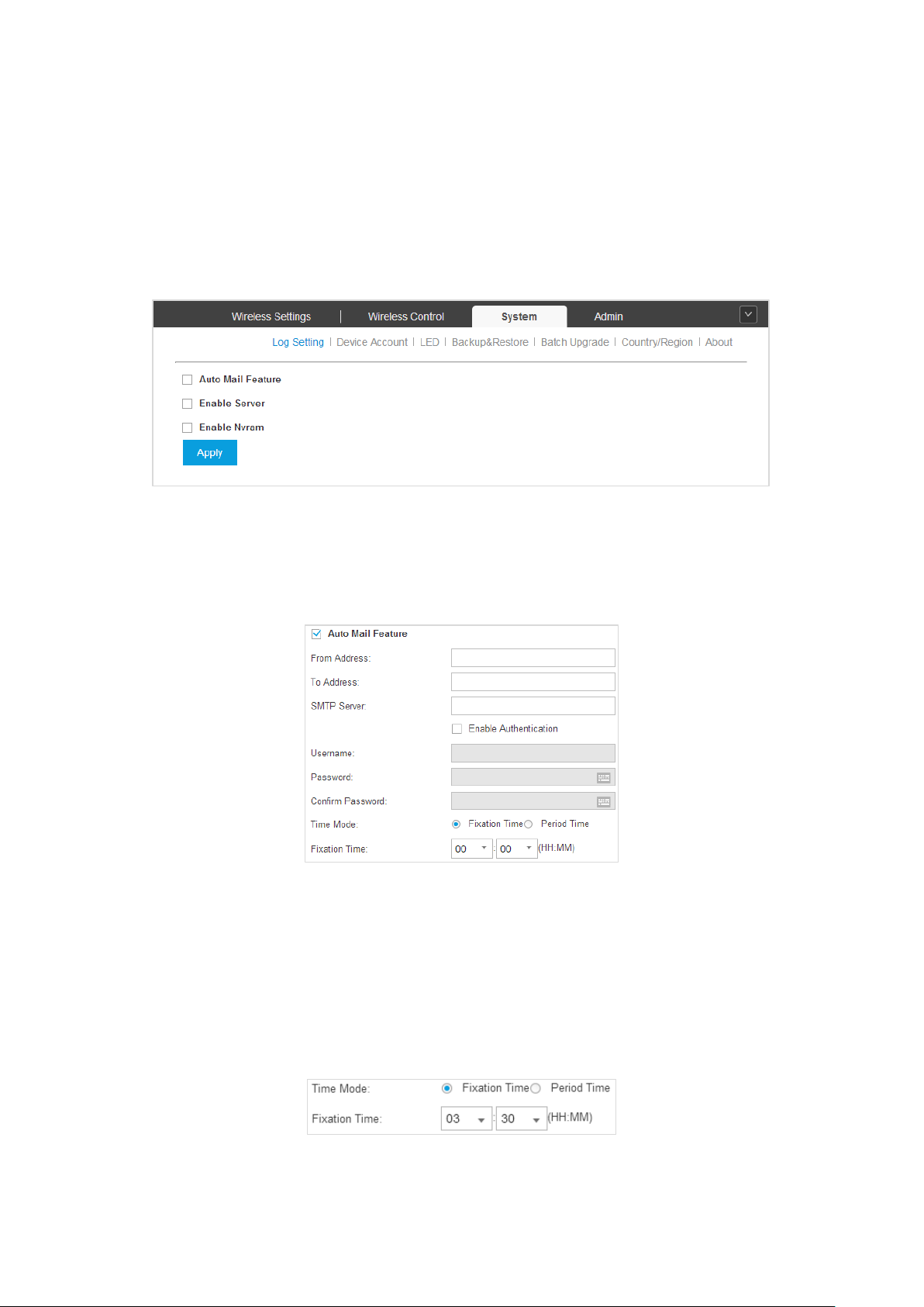
4.3.1 Log Setting
You can choose the way to receive system logs on Log Setting page. These parameters can be configured:
Auto Mail Feature, Enable Server and Enable Nvram.
Auto Mail Feature
If Auto Mail Feature is enabled, system logs will be sent to a specified mailbox. After checking the Auto
Mail Feature box, the following screen will appear.
Enter the sender’s mail address, the receipt’s address and the IP address of the SMTP server.
You can check the Enable Authentication box to enable mail server authentication. Enter the sender’s
mail account name and password.
System logs can be sent at specific time or time interval. Select Time Mode:
Fixation Time: Specify a fixed time to send the system log mails. You can respectively select the hour
number and the minute number.
37
Page 42

EAP Controller User Guide Chapter 4 Global Setting
Period Time: Specify a period time to regularly send the system log mail. For example, 5 indicates
that the mail will be sent once every five hours.
Enable Server
System logs can also be sent to a server. You can enable the system log server and enter its IP address and
port.
Enable NVRAM
NVRAM (Non-volatile Random Access Memory) is a RAM that can still save data even if a device powers
off. The Nvram feature can help reserve the system logs when an EAP device powers off. By default, it is
disabled.
4.3.2 Device Account
You can change the EAP devices ’ username and password to protect them from being illegally adopted.
After the EAP devices are adopted at the first time, their username and password will change into the
username/password (current username/password) of the admin account created at Quick Setup. You can
directly specify a new username and password for them. If these EAPs have already been adopted, the
Controller will push configuration of the new specified username and password to each EAP device.
38
Page 43

EAP Controller User Guide Chapter 4 Global Setting
4.3.3 LED
The LED page allows you to turn on/off the LED lights of EAPs.
4.3.4 Backup&Restore
You can save the current configuration of the EAPs as a backup file and if necessary, restore the
configuration using the backup file. It is recommended to back up the settings before you upgrade the
device.
NOTE:
The format of the restore file is “.cfg”.
4.3.5 Batch Upgrade
On the Batch Upgrade page, you can upgrade the EAP devices in batches according to their model.
Select the EAP model and display the EAP amount. Click Browse to locate and choose the upgrade file in
your PC. Then click Upgrade to finish the batch upgrading.
39
Page 44
EAP Controller User Guide Chapter 4 Global Setting
NOTE:
Please visit http://www.tp-link.com/en/support/download/ to download the latest firmware file of
the corresponding model.
Please select the proper software version that matches your hardware to upgrade.
To avoid damage, please do not turn off the device while upgrading.
After upgrading, the device will reboot automatically.
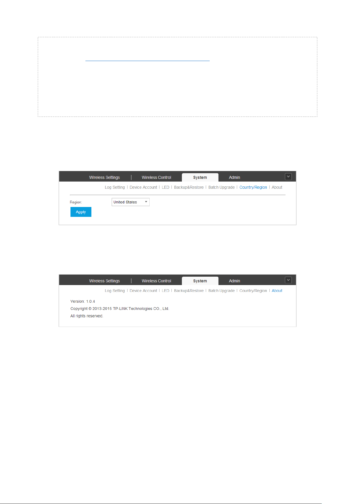
4.3.6 Country/Region
On the Country/Region page, you can re-select your country or region. Please comply with local laws.
Incorrect selection may violate local regulations.
4.3.7 About
This page displays the EAP Controller software’s version and copyright information.
4.4 Admin
On the Admin page you can configure the user account for login to the EAP Controller. User has three
roles: administrator, operator or observer. The administrator user was created at the Quick Setup. It can
change the settings of the EAP network and even administrate other users. The operator can only write
and read. The observer can just read system information.
When you log into the EAP Controller with the administrator account, the Admin page includes three sub-
pages: User Settings, Role and Controller Settings. Logging with the operator or observer account, you
can only view User Info on the Admin page.
40
Page 45

EAP Controller User Guide Chapter 4 Global Setting
4.4.1 User Settings
The User Settings page displays user’s name, email address, role and created time.
Add User
Step 1: Click and specify the name, email address, role and password for a new user.
Click Apply and the new user will successfully be added in the list.
41
Page 46

EAP Controller User Guide Chapter 4 Global Setting
Step 2: In the Action column, click to edit the user and a window will appear as below.
You can specify a new email address for the admin user and change the current password. For the added
administrator, operator and observer users, you can also change their roles and even delete them. But the
admin user created at the Quick Setup cannot be deleted and even its username/role cannot be changed.
4.4.2 Role
The Role page displays user role’s type, description information, permission scope, and created time.
The observer user can only view the settings of the EAPs. The operator user cannot only view the settings,
but it can also configure the EAPs. However, the administrator user can even manage the operator and
observer user besides writing and reading.
42
Page 47

EAP Controller User Guide Chapter 4 Global Setting
4.4.3 Controller Settings
The Controller Settings page is used for configuring the system settings of the EAP Controller.
EAP Controller
Controller Hostname/IP: Enter the hostname or IP address of the EAP Controller.
NOTE:
When you reset the admin password, the Controller will send alert emails to your email box. In every
message there is a Controller URL, in which the Controller Hostname/IP will be specified.
Mail Server
NOTE:
Here set the Mail Server for sending the notifications and resetting the user login password, different from
the SMTP Server setting just for sending and receiving the syslog emails.
When enabled, EAP will send email alerts triggered by Pending APs and Disconnected APs. Specify the
administrator email address when you create an account under Admin > User Settings.
43
Page 48

EAP Controller User Guide Chapter 4 Global Setting
Enable SMTP Server: Select this option to enable emails.
Mail Server: Enter the IP address or domain of SMTP Server.
Port: The default is 25. If Security Socket Layer (SSL) is enabled, then the port number will
automatically change to 465.
Enable SSL: You can enable SSL to enhance secure communications over the Internet.
Enable Auth: Select this option to enable authentication.
Username: Enter the username required by the mail server.
Password: Enter the password required by the mail server.
Specify Sender Address: Specify the sender’s mail address. Enter the email address that will appear
as the sender of the email alert.
After setting the Mail Server, you can reset the password when you forget it. Click Forgot password? on
the login page of the EAP Controller, then the following screen will appear.
Enter your email address registered when creating the user account. Click Reset Password and go to your
email box to reset your password.
44
Page 49

EAP Controller User Guide Chapter 5 AP Details
Chapter 5 AP Details
Clicking the AP’s name on the Access Points tab or clicking of connected AP on the map will open a
window displaying the Details, User, Guest, and Configuration information of the AP.
5.1 Details
The Details tab displays the detailed information about the AP.
5.1.1 Overview
Click Overview to view the basic information including AP’s name/MAC address, IP address, model,
software version, the usage rate of CPU/Memory and uptime (the amount of time the AP has been
running without interruption).
5.1.2 LAN
Click LAN to view the traffic information of receiving/transmitting, including the total number of packets
received/transmitted, the total size of data received/transmitted, the total number of packets loss on the
AP during receiving/transmitting, and the total size of error data on the AP during receiving/ transmitting.
45
Page 50

EAP Controller User Guide Chapter 5 AP Details
5.1.3 Radio
Click Radio to view the radio information including the frequency band, the wireless mode, the channel
width, the channel, and the transmitting power. At 2.4GHz, you can also view parameters of
receiving/transmitting data.
5.2 User
The User tab displays the information of client connecting to the EAP wireless network, including its MAC
address and connected SSID. You can click the MAC address to get its connection history.
46
Page 51

EAP Controller User Guide Chapter 5 AP Details
5.3 Guest
The Guest tab displays the information of clients connecting to the EAP wireless network with the Portal
authentication, including their MAC addresses and connected SSID. You can click to cancel the
authentication for it.
5.4 Configuration
The Configuration tab allows you to modify this AP’s name, set the IP address, select the radio mode,
enable the load balance function, set new SSID overriding the old one, enable Rogue AP detection feature,
and forget this AP. All the configurations on this AP will only take effect on this device.
5.4.1 Basic Config
You can change the name of this EAP.
47
Page 52

EAP Controller User Guide Chapter 5 AP Details
5.4.2 IP Setting
You can configure an IP address and subnet mask for this EAP.
Select DHCP/Static to set the IP address.
DHCP: Select to get a dynamic IP address from the DHCP server.
48
Page 53

EAP Controller User Guide Chapter 5 AP Details
Fallback IP: Select whether to enable the Fallback IP feature.
Fallback IP Address: Configure a fallback IP address for the AP. Fallback IP address is a secondary
address.
Fallback IP Mask: Set a subnet mask for the fallback IP address.
Fallback Gateway: Set a gateway for the fallback IP address.
Static: Select to manually configure a static IP address.
IP Address: Configure an IP address for the AP.
IP Mask: Set an IP mask for the static address you configured.
Gateway: Set a gateway for the static address you configured.
5.4.3 Radio
Radio settings directly control the access of wireless clients to the EAP device.
49
Page 54

EAP Controller User Guide Chapter 5 AP Details
Select the frequency band (2.4GHz/5GHz) you want to configure. By default, the radio of this AP is
enabled.
Select the IEEE 802.11 Mode the radio uses. When selecting the frequency of 2.4GHz, three modes are
available:
802.11b/g/n mixed: All of 802.11b, 802.11g, and 802.11n clients operating in the 2.4GHz frequency
can connect to the EAP device. It is recommended to select the 802.11b/g/n mixed mode.
802.11b/g mixed: Both 802.11b and 802.11g clients can connect to the EAP device.
802.11n only: Only 802.11n clients can connect to the EAP device.
When the frequency of 5GHz is selected, 802.11a/n mixed, 802.11a only, and 802.11n only modes are
selectable.
802.11a/n mixed: Both 802.11a clients and 802.11n clients operating in the 5GHz frequency can
connect to the EAP device. It is recommended to select the 802.11a/n mixed mode.
802.11a only: Only 802.11a clients can connect to the EAP device.
802.11n only: Only 802.11n clients can connect to the EAP device.
Select the Channel Width of the EAP device. The 20/40 MHz channel enables higher data rates but leaves
fewer channels available for use by other 2.4GHz and 5GHz devices. By default, when the radio mode
includes 802.11n, the channel bandwidth is set to 20/40 MHz to enable both channel widths.
50
Page 55
EAP Controller User Guide Chapter 5 AP Details
Select the Channel used by the EAP device to improve wireless performance. The range of available
channels is determined by the radio mode and the country setting. If you select Auto for the channel
setting, the EAP device scans available channels and selects a channel where the least amount of traffic
is detected.
Enter the Tx Power (transmit power) value. The maximum transmit power may vary among different
countries and regions.
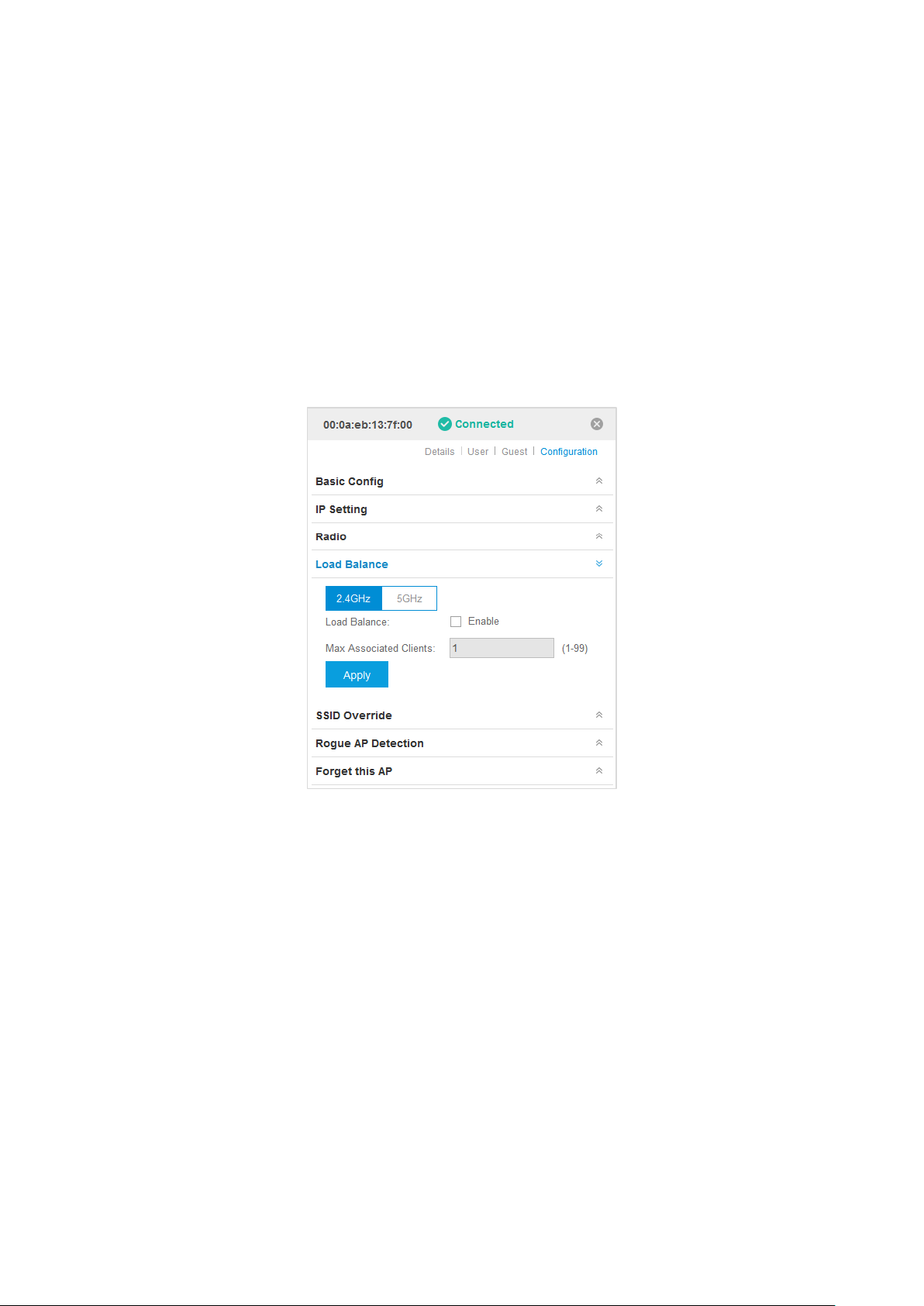
5.4.4 Load Balance
By restricting the maximum number of clients accessing the EAPs, Load Balance helps to achieve rational
use of network resources.
Select the frequency band (2.4GHz/5GHz) and enable the Load Balance function. If this function is
enabled, you can specify the maximum number of connected clients. While more clients want to connect,
the EAP will begin to check those with lower signals and disconnect them.
5.4.5 SSID Override
Click SSID Override, select the frequency band and the table will display the previous network name.
51
Page 56

EAP Controller User Guide Chapter 5 AP Details
In the Action column, click to configure a new SSID to override the previous one.
Enable: Select whether to enable the SSID override feature.
VLAN: You can allow the overridden SSID to join a VLAN. Check the User VLAN ID box and specify a
VLAN ID.
SSID: Specify a new network name.
PSK: Specify a password to encrypt the new SSID.
Click Apply to save your configurations.
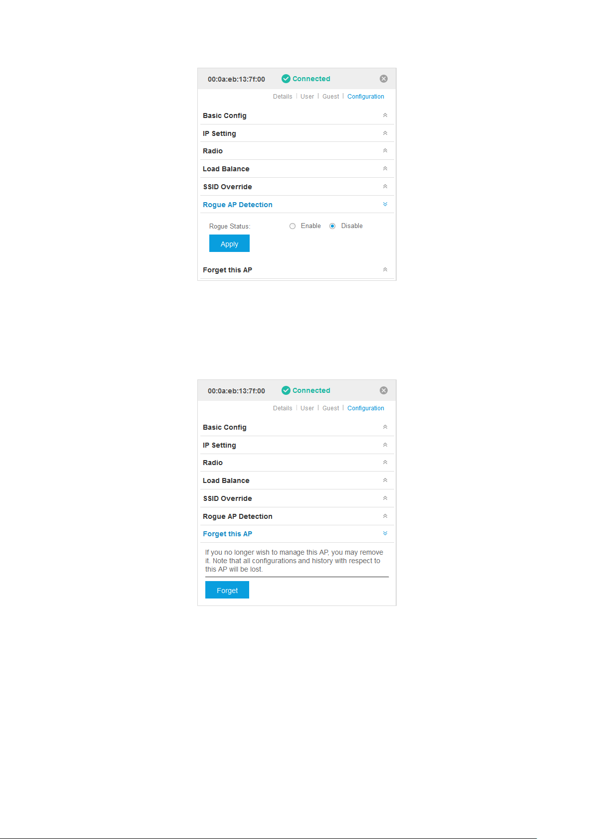
5.4.6 Rogue AP Detection
You can enable or disable the Rogue Status of the AP. All channels will be detected and connected clients
will disconnect with the AP during the detection time.
52
Page 57
EAP Controller User Guide Chapter 5 AP Details
5.4.7 Forget this AP
If you no longer want to manage this AP, you may remove it. But all the configurations and history about
this AP will be lost. It is recommended to back up the configurations of this AP.
53
Page 58
EAP Controller User Guide Chapter 6 Application Example
Chapter 6 Application Example
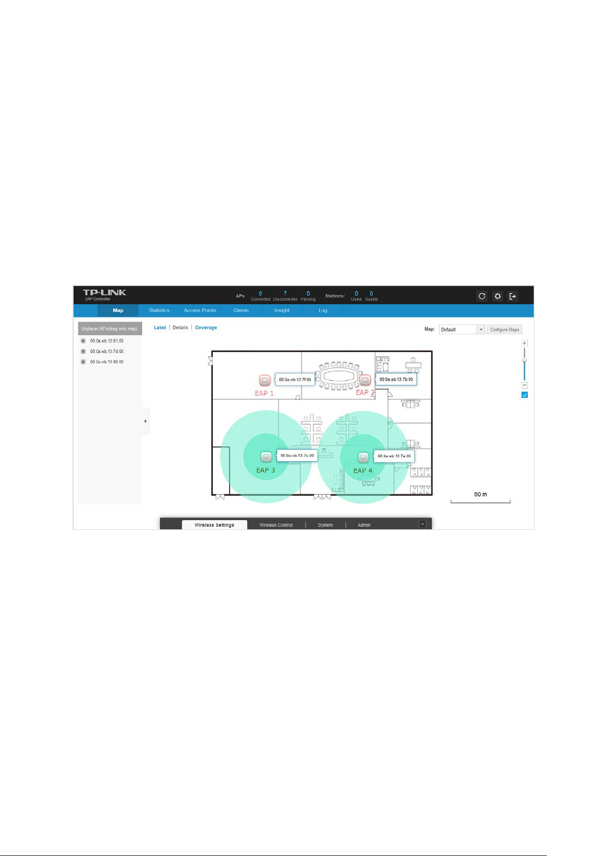
6.1 Map Monitor
The distinctive function of the EAP Controller is monitoring the running situation of all the EAPs and
vividly presenting it on the map. The following is a simple but typical example.
In a small enterprise, the network administrator deploys four EAP devices according to the preceding part
of the UG. On the top of the interface apparently displays two devices being disconnected. And we can
see that EAP1 and EAP2 are disconnected on the map. In this case, the network administrator can quickly
locate them and find out the causes with the help of the log feature.
6.2 Portal Authentication
The portal authentication, also known as web authentication, is an effective way to manage the large
wireless network in the places such as hotel, community, company or some other public places. The
administrator can provide each user with an individual account. Furthermore, the web portal can be used
to announce ads, notices and some other personalized information. The following is a supposed example
that the portal authentication is used on a supermarket network.
Supermarket A has a large EAP wireless network. The network administrator wants to drive customers’
attention to the promotion information of Supermarket A. So he decides to employ the portal
authentication.
Here are the network parameters of Supermarket A:
SSID Name: TP-LINK_Supermarket A,
54
Page 59

EAP Controller User Guide Chapter 6 Application Example
Website: www.supermarketa.com,
IP of External Radius Server: 192.168.1.103, port: 1812,
External Web Portal URL: www.supermarketa.net,
IP/subnet mask of External Web Server: 175.20.20.115/32, port: 80.
The network administrator can perform the following steps to set the Portal authentication for the EAP
network.
Step 1: Sign in to the EAP Controller management interface and go to Wireless Settings > Basic Wireless
Setting.
Step 2: Select the SSID you want to enable the portal authentication and click . Then the following
window will pop up. Check the Portal Enable box.
Step 3: Go to Wireless Control > Portal.
There are three authentication types available.
Select No Authentication in Authentication Type. Users can access the network without the
username and password on the web portal page.
55
Page 60

EAP Controller User Guide Chapter 6 Application Example
It is recommended to select Local Password as shown below. Specify a username and password that
will be stored on the EAPs and all users are required to enter the username and password to access
the wireless network. You can set a proper authentication timeout that determines how long the
users can stay online once they authenticate with the EAPs.
Select External Radius Server as shown below. Enter the Radius Server IP, Port and Radius
Password of Radius server. The Radius password is the secret key between the Radius server and the
Radius client. The Radius password is always specified by the administrator of Radius server. You can
also set a proper Authentication Timeout.
Step 4: This feature is optional. If you want to lead users to pre-defined web pages (for instance, your
official website or supermarket promotion pages) after users pass the web authentication, check
the Redirect box and enter the Redirect URL.
Step 5: Customize the web portal page. You can either select the built-in Local Web Portal or the
External Web Portal.
56
Page 61

EAP Controller User Guide Chapter 6 Application Example
It is recommended to select Local Web Portal in the Portal Customization list. Then the following
page will be shown. The web portal title and Term of Use are customizable.
If External Radius Server is configured above, select External Web Portal. Enter External Web
Portal URL as shown below.
Moreover, you must put the external Web portal server to a whitelist of Free Authentication Policy,
otherwise clients cannot access the external Web server before authentication.
Click on the Free Authentication Policy page and the following window will pop up.
57
Page 62

EAP Controller User Guide Chapter 6 Application Example
Specify the policy name and enter the Source IP Range with the subnet and mask of the clients. Then set
the IP address and subnet mask of external Web server as Destination IP Range. The default Destination
Port is 80. You should assign the service port of external Web server if the port number is not 80. Check
the Status box to enable the policy.
Click Apply to finish the configuration of policy.
Step 6: Click Apply on the Portal page to finish your configuration.
The following are the visual effect how users log into the wireless network after finishing the above
configurations.
Connect your wireless devices to the wireless network TP-LINK_Supermarket A. Open your browser and
try to visit any website, you will be directed to the web portal page.
No Authentication is selected in Step 3. The page will show as below. Users need to read the Te rm
of Use and check the box to log in.
When the Local Password or the External Radius Server is configured, and the Local Web Portal
is selected, the following page will show. Users need to input the username and password and accept
the Term of Use.
58
Page 63

EAP Controller User Guide Chapter 6 Application Example
When External Radius Server is configured and External Web Portal is selected, the browser will
be directed to the External Web Portal URL. Users can refer to the page to access more resources
by an authentication or in other way. The following is a simple example.
Click LOGIN and the web browser will be redirected to the Redirect URL. And then users can surf the
Internet freely.
59
 Loading...