

Page 1

EAP110-Outdoor
Installation Guide
300Mbps Wireless N Outdoor Access Point
Page 2

Page 3

Contents
Overview
Typical Network Topology
Lightning and ESD Protection
Hardware Installation
Mount EAP
Connect Cables
Power On
Software Configuration
4
5
6
7
9
10
11
Page 4
Overview
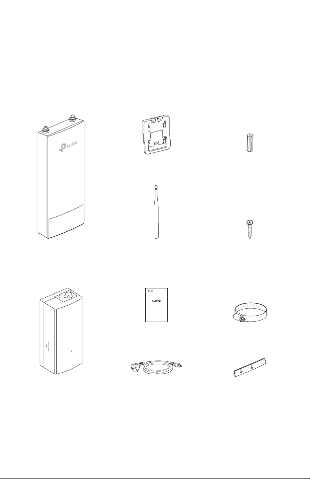
Package Contents
EAP
Passive PoE Adapter
Mounting Bracket
Antennas (Qty.2)
EAP110-Outdoor
Installation Guide
300Mbps Wireless N Outdoor Access Point
Power Cord
M3×28 Plastic Wall
Anchors(Qty.3)
M3×20 Self-tapping
Screws (Qty.3)
Metal StrapInstallation Guide
Waterproof Rubber
Insert
1
Page 5
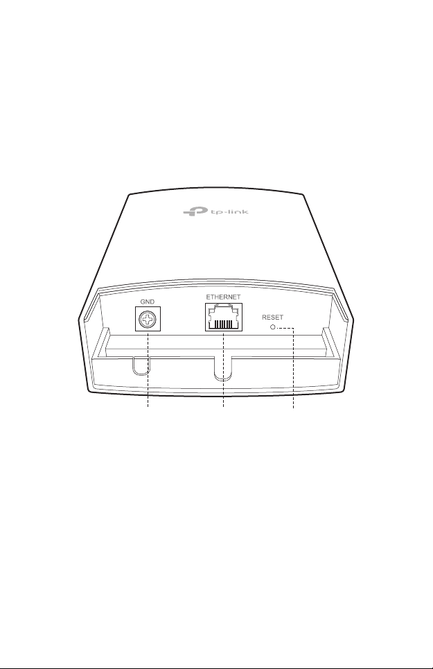
Panel Layout
The Panel of EAP
Grounding
Terminal
Shielded Ethernet
Port LAN
2
RESET
Page 6

SYS LED Explanation
LED Status Indication
Flashes green, red
and yellow before
remaining green
Flashes green twice Initialization is completed.
Solid green The device is working properly .
The device is initializing.
Flashes red System errors. RAM, Flash, Ethernet, WLAN or
Flashes yellow Firmware update is in progress. Do not disconnect
Double ashes red,
green, yellow
rmware may be malfunctioning.
or power o the device.
The device is being reset to its factory default
settings.
Passive PoE Adapter
Remote Reset:
Press and hold for 8 seconds
to reset the EAP to its factory
default settings.
Power LED:
The Power LED indicates the
status of the electric current:
On: Supplying power.
Off: Not supplying power.
3
Page 7

Typical Network Topology
Internet
Router
Switch
EAP Controller
Manangement Host
A DHCP server (typically a router) with DHCP function enabled is required to
assign IP addresses to the EAPs and clients in your local network.
EAP EAP EAP
Clients
4
Page 8

Lightning and ESD Protection
Before mounting EAP, you should consider Lightning and ESD
Protection to ensure safety.
Proper grounding is extremely important for outdoor devices.
There are two effective techniques for grounding the outdoor
EAP:
Option A
Use a shielded CAT5e (or above) cable with an integrated
grounding wire for connection.
Option B
If you have the standard CAT5e cable for the connection, use a
separate grounding cable to connect the grounding Terminal
(GND) to earth ground.
5
Page 9

EAP
Grounding
Terminal
Grounding Wire
Shielded CAT5e (or above)
Cable with
Grounding Wire
BAGrounding
Cable
Earth Ground
an Integrated
A
Grounded PoE Adapter
Hardware Installation
Mount EAP
The EAP can be pole-mounted or wall-mounted.
6
Grounded 3-wire
Power Outlet
Page 10

Option 1: Pole Mounting
Step 1:
Loosen and completely remove the
end of the metal strap by turning the
captive screw counterclockwise
with a flathead screwdriver.
Step 2:
Lead the end of the metal strap
through the back of the EAP.
Step 3:
Position the EAP and wrap the metal
strap around the pole. Feed the end
back through the screw-block and
turn the screw clockwise to tighten
the metal strap using a flathead
screwdriver until the EAP is secure.
Step 4:
Connect the antennas to the EAP.
7
Page 11

Option 2: Wall Mounting
Step 1:
Place the mounting bracket in the
right position. Mark three positions
for the screw holes .
Drill three 6mm holes for the
screws at the marked positions.
Step 2:
Insert the plastic wall anchors into
the 6mm holes. Align the bracket
to the plastic wall anchors and
drive the self-tapping screws into
the anchors through the bracket.
Step 3:
Align the mounting tabs on the
back of the EAP with the four slots
of the mounting bracket. Push and
slide the EAP downward until it
locks into place.
Step 4:
Connect the antennas to the EAP.
8
Page 12

Connect Cables
Step 1:
Firmly grasp the rear of the interface
cover and pull it downward.
Step 2:
Use an adequate Ethernet cable to
connect the LAN port. The length of
cable is up to 60m for steady power
supply. Shielded CAT5e (or above)
cable with an integrated ground wire
is recommended.
Step 3:
Affix the waterproof rubber insert to
the underside of the device for
waterproofing and replace the cover
until it firmly locks into place.
9
Page 13

Power On
Connect the EAP to a Power over Ethernet (PoE) adapter as
follows:
PoE LAN
Ethernet cable length up to 60m
Step 1:
Connect the Ethernet cable from the EAP to the POE port of the
PoE adapter.
Step 2:
Connect the power cord to the power port on the PoE adapter
and plug it into an electrical outlet.
Step 3:
Connect an Ethernet cable from your LAN device (a computer,
router or switch) to the LAN port on the PoE adapter.
10
Page 14

Software Conguration
The EAP supports two configuring options:
To configure and manage mass EAPs via centralized controller software, please
refer to Option 1.
To configure a single EAP via a web browser directly, please refer to Option 2.
Option 1: Via EAP Controller
Step 1: Installing the EAP Controller
On the PC, download the EAP Controller installation file from
http://www.tp-link.com/en/download/EAP-Controller.html. Run
the file and follow the wizard to install the EAP Controller.
Step 2: Configuring the EAP Controller
Launch the EAP Controller and follow the step-by-step
instructions to complete the Quick Setup. After the wizard is
finished, a login screen will appear.
Step 3: Logging in to the EAP Controller
Enter the admin name and password you created and click Sign
In. Then you can further configure the EAP Controller.
For More Configurations
Now you can manage your wireless network and view network
statistics using the EAP Controller. Please refer to the EAP
Controller User Guide to learn more information about
conguring and using the Controller software.
11
Page 15

Option 2: Via Web Browser
Step 1: Connecting to the EAP Device
Power on the EAP and connect wirelessly by using the default
SSID (format: TP-LINK_2.4GHz/5GHz_XXXXXX).
Step 2: Logging in to the EAP Device
Launch a web browser and enter http://tplinkeap.net in the
address bar. Use admin for both Username and Password to log
in.
Step 3: Configuring the EAP device
Set up a new Username and Password for secure management
purpose. Modify the wireless parameters and reconnect your
wireless devices to the new wireless network.
12
Page 16

For technical support and other information, please visit
The products of TP-Link partly contain software code developed by third parties, including software code subject to the GNU
General Public License (“GPL”). As applicable, the terms of the GPL and any information on obtaining access to the respective
GPL Code used in TP-Link products are available to you in GPL-Code-Centre under (http://www.tp-link.com/en/suppor t/gpl/).
The respective programs are distributed WITHOUT ANY WARRANTY and are subject to the copyrights of one or more authors.
For details, see the GPL Code and other terms of the GPL.
http://www.tp-link.com/support, or simply scan the QR code.
© 2017 TP-Link 7106507583 REV1.0.2
 Loading...