

Page 1

User Guide
AC1200/1900 Wireless Dual Band Gigabit Access Point
EAP320/EAP330
REV1.0.0
1910011564
Page 2

CE Mark Warning
This subsection does not apply for the geographical area
. Permitted for use SRD for
outdoor applications without restriction on installation
Permitted to use SRD for other purposes for outdoor
applications only when the installation height is not
2. SRD with DSSS and other than FHSS wideband
This is a class B product. In a domestic environment, this product may cause radio interference,
in which case the user may be required to take adequate measures.
RF Exposure Information
This device meets the EU requirements (1999/519/EC) on the limitation of exposure of the
general public to electromagnetic fields by way of health protection.
The device complies with RF specifications when the device used at 20 cm from your body.
National Restrictions
This device is intended for home and office use in all EU countries (and other countries following
the EU directive 1999/5/EC) without any limitation except for the countries mentioned below:
Country Restriction Reason/remark
Belarus Not implemented
Norway Implemented
within a radius of 20 km from the centre of Ny-Ålesund on
Svalbard.
Italy Implemented The public use is subject to general authorisation by the
respective service provider.
Russian
Federation
Limited
implementation
1. SRD with FHSS modulation
1.1. Maximum 2.5 mW e.i.r.p.
1.2. Maximum 100 mW e.i.r.p
height only for purposes of gathering telemetry information
for automated monitoring and resources accounting systems.
exceeding 10 m above the ground surface.
1.3.Maximum 100 mW e.i.r.p. Indoor applications.
modulation
2.1. Maximum mean e.i.r.p. density is 2 mW/MHz. Maximum
100 mW e.i.r.p.
2.2. Maximum mean e.i.r.p. density is 20 mW/MHz. Maximum
Page 3

100 mW e.i.r.p. It is permitted to use SRD for outdoor
applications only for purposes of gathering telemetry
information for automated monitoring and resources
accounting systems or security systems.
2.3. Maximum mean e.i.r.p. density is 10 mW/MHz. Maximum
100 mW e.i.r.p. Indoor applications.
Ukraine Limited
implementation
e.i.r.p. ≤100 mW with built-in antenna with amplification
factor up to 6 dBi.
ATTENTION: Due to EU law, the country settings must be identical to the country where the
device is operating (important due to non-harmonised frequencies in the EU).
Restricted to indoor use.
Продукт сертифіковано згідно с правилами системи УкрСЕПРО на відповідність вимогам
нормативних документів та вимогам, що передбачені чинними законодавчими актами
України.
Safety Information
When product has power button, the power button is one of the way to shut off the product;
when there is no power button, the only way to completely shut off power is to disconnect
the product or the power adapter from the power source.
Don’t disassemble the product, or make repairs yourself. You run the risk of electric shock
and voiding the limited warranty. If you need service, please contact us.
Avoid water and wet locations.
Adapter shall be installed near the equipment and shall be easily accessible.
The plug considered as disconnect device of adapter.
Use only power supplies which are provided by manufacturer and in the original
packing of this product. If you have any questions, please don't hesitate to contact us.
Page 4

This product can be used in the following countries:
This product bears the selective sorting symbol for Waste electrical and electronic
equipment (WEEE). This means that this product must be handled pursuant to European
2012/19/EU in order to be recycled or dismantled to minimize its impact on the
AT BG BY CA CZ DE DK EE
ES FI FR GB GR HU IE IT
LT LV MT NL NO PL PT RO
RU SE SG SK TR UA US
Explanation of the symbols on the product label
Symbol Explanation
DC voltage
RECYCLING
directive
environment.
User has the choice to give his product to a competent recycling organization or to the
retailer when he buys a new electrical or electronic equipment.
Page 5

TP-LINK TECHNOLOGIES CO., LTD
DECLARATION OF CONFORMITY
For the following equipment:
Product Description: Wireless Dual Band Gigabit Access Point
Model No.: EAP320/EAP330
Trademark: TP-LINK
We declare under our own responsibility that the above products satisfy all the technical
regulations applicable to the product within the scope of Council Directives:
Directives 1999/5/EC, Directives 2006/95/EC, Directives 1999/519/EC, Directives 2011/65/EU
The above product is in conformity with the following standards or other normative documents
EN 300 328 V1.8.1
EN 301 489-1 V1.9.2 & EN 301 489-17 V2.2.1
EN 60950-1: 2006 + A11: 2009 + A1: 2010 + A12: 2011 +A2: 2013
EN 50385: 2002
EN 301 893 V1.7.1
The product carries the CE Mark:
Person responsible for making this declaration:
Yang Hongliang
Product Manager of International Business
Date of issue: 2015-12-18
TP-LINK TECHNOLOGIES CO., LTD.
Building 24 (floors 1, 3, 4, 5), and 28 (floors 1-4) Central Science and Technology
Park, Shennan Rd, Nanshan, Shenzhen, China
Page 6

About this User Guide
This User Guide is for EAP320 and EAP330. Chapter 4 to Chapter 8 are only suitable for the EAP
in Standalone mode. Refer to the EAP Controller User Guide when the EAP is managed by the
EAP Controller software.
Convention
Unless otherwise noted, the EAP or the device mentioned in this guide stands for AC1200
Wireless Dual Band Access Point EAP320, AC1900 Wireless Dual Band Access Point EAP330.
Page 7

CONTENTS
Chapter 1 Introduction ...................................................................................................................................... 3
1.1 Overview of the EAP ........................................................................................................................... 3
1.2 Hardware Overview ............................................................................................................................ 3
1.2.1 LED ................................................................................................................................................... 3
1.2.2 Interface Panel ............................................................................................................................. 4
Chapter 2 Network Topology .......................................................................................................................... 5
Chapter 3 Management Mode ........................................................................................................................ 6
3.1 Standalone Mode ................................................................................................................................. 6
3.2 Managed Mode .................................................................................................................................... 6
3.3 Switch to Standalone Mode ............................................................................................................. 6
Chapter 4 Network .............................................................................................................................................. 7
Chapter 5 Wireless ............................................................................................................................................... 8
5.1 Wireless Settings .................................................................................................................................. 9
5.1.1 Wireless Basic Settings .......................................................................................................... 10
5.1.2 SSIDs ............................................................................................................................................. 11
5.1.3 Wireless Advanced Settings ................................................................................................ 15
5.1.4 Load Balance ............................................................................................................................. 16
5.2 Portal ...................................................................................................................................................... 16
5.2.1 Portal Configuration ............................................................................................................... 17
5.2.2 Free Authentication Policy ................................................................................................... 22
5.3 MAC Filtering ...................................................................................................................................... 24
5.4 Scheduler ............................................................................................................................................. 26
5.5 QoS ......................................................................................................................................................... 30
5.5.1 AP EDCA Parameters .............................................................................................................. 31
5.5.2 Station EDCA Parameters ..................................................................................................... 32
5.6 Rogue AP Detection ......................................................................................................................... 33
5.6.1 Settings ....................................................................................................................................... 34
5.6.2 Detected Rogue AP List ........................................................................................................ 34
5.6.3 Trusted AP List .......................................................................................................................... 35
5.6.4 Download/Backup Trusted AP List .................................................................................... 36
1
Page 8

Chapter 6 Monitoring ...................................................................................................................................... 37
6.1 AP ............................................................................................................................................................ 37
6.1.1 AP List .......................................................................................................................................... 37
6.2 SSID ........................................................................................................................................................ 42
6.2.1 SSID List ....................................................................................................................................... 42
6.3 Client ...................................................................................................................................................... 43
6.3.1 User List ....................................................................................................................................... 43
6.3.2 Portal Authenticated Guest ................................................................................................. 44
Chapter 7 Management ................................................................................................................................. 46
7.1 System Log .......................................................................................................................................... 46
7.1.1 Log List ........................................................................................................................................ 46
7.1.2 Log Settings ............................................................................................................................... 47
7.1.3 Backup Log ................................................................................................................................ 48
7.2 Web Server .......................................................................................................................................... 49
7.3 Management Access ........................................................................................................................ 49
7.4 Trunk ...................................................................................................................................................... 50
7.5 LED ON/OFF ........................................................................................................................................ 51
7.6 SSH .......................................................................................................................................................... 51
7.7 SNMP ..................................................................................................................................................... 52
Chapter 8 System .............................................................................................................................................. 55
8.1 User Account ....................................................................................................................................... 55
8.2 Time Settings ...................................................................................................................................... 55
8.2.1 Time Settings ............................................................................................................................ 56
8.2.2 Daylight Saving ........................................................................................................................ 57
8.3 Reboot/Reset ...................................................................................................................................... 58
8.4 Backup & Restore .............................................................................................................................. 59
8.5 Firmware Upgrade ............................................................................................................................ 59
Appendix A: Specifications ................................................................................................................................ 61
2
Page 9
System LED
Chapter 1 Introduction
1.1 Overview of the EAP
EAP series products provide wireless coverage solutions for small-medium business. They can
either work independently as standalone APs or be centrally managed by the EAP Controller
software, providing a flexible, richly-functional but easily-configured enterprise-grade wireless
network for small and medium business.
“Celling lamp” appearance and easily mounting design with chassis make EAP easy to be
installed on a wall or ceiling and blend in with most interior decorations.
EAP320/EAP330 can be powered via a PSE* device or the provided power adapter.
With the built-in dual-band antennas module, EAP320/EAP330 operate at both 2.4GHz and 5GHz,
and apply 802.11ac standards and MIMO technology, allowing packet transmission at up to
1200Mbps/1900Mbps.
*PSE: Power Sourcing Equipment, a device (switch or hub for instance) that will provide power
in a PoE setup.
1.2 Hardware Overview
1.2.1 LED
EAP320 and EAP330 have the same LED status and corresponding indications.
Figure 1-1 Top View of the EAP
3
Page 10
LED Status Indication
Solid green
The device is working properly.
Flashing red
System errors. RAM, flash, Ethernet, WLAN or firmware
Flashing yellow
Firmware update is in progress. Do not disconnect or
Double-flashing red, green, yellow
The device is being reset to its factory default settings.
may be malfunctioning.
power off the device.
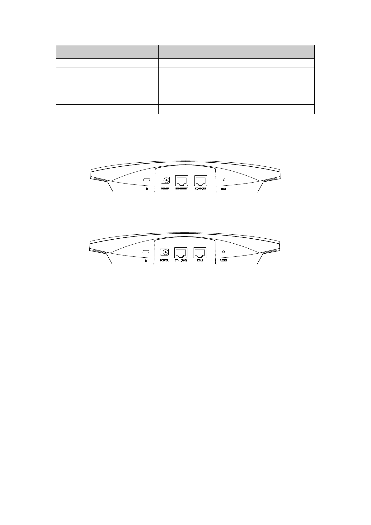
1.2.2 Interface Panel
EAP320:
Figure 1-2 Interface Panel of EAP320
EAP330:
Figure 1-3 Interface Panel of EAP330
Kensington Security Slot: Secure the lock (not provided) into the security slot to prevent
the device from being stolen.
RESET: With the device powered on, press and hold the RESET button for about 5 seconds
until the LED flashes red, then release the button. The device will restore to factory default
settings.
CONSOLE: This port is used to connect to the serial port of a computer or a terminal to
check and monitor system information of the EAP320.
Note: CLI commands are not available in current software version. We will release a new
version supporting CLI commands soon. Please pay close attention to our official website.
ETHERNET/ETH1(PoE):
This port is used to connect to the POE port of the provided PoE adapter for both data
transmission and power supply through Ethernet cabling.
POWER: The power port is used to connect the EAP320/EAP330 to an electrical wall outlet
via power adapter. Please only use the provided power adapter.
4
Page 11
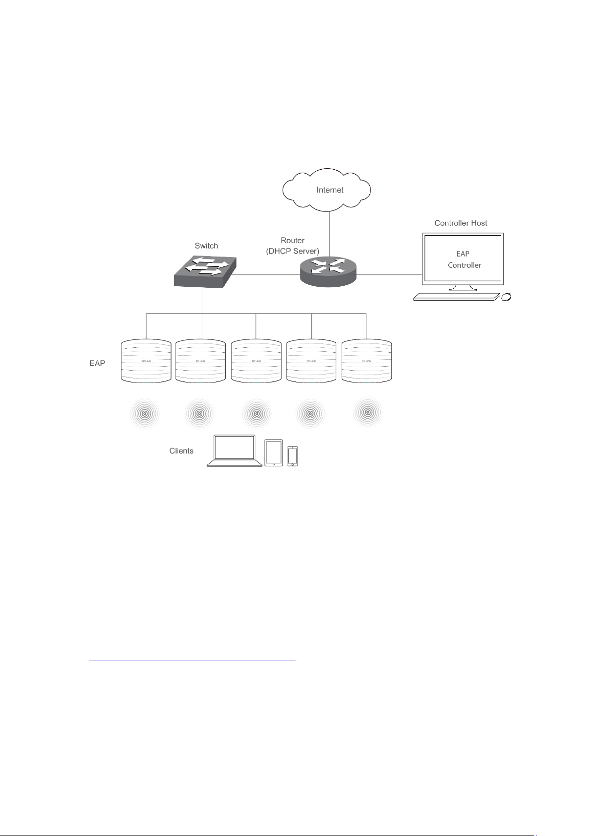
Chapter 2 Network Topology
A typical network topology for the EAP is shown below.
Figure 2-1 Typical Topology
To deploy an EAP in your local network, a DHCP server is required to assign IP addresses to the
EAP and clients. Typically, a router acts as the DHCP server. A computer running the EAP
Controller software can locate in the same or different subnet with the EAPs.
The EAP can be managed by the EAP Controller software, which is a management software
specially designed for the TP-LINK EAP devices on a local wireless network, allowing you to
centrally configure and monitor mass EAP devices using a web browser on your PC. For more
information about the EAP Controller, please refer to the EAP Controller User Guide from our
official website:
http://www.tp-link.com/en/support/download/
5
Page 12

Chapter 3 Management Mode
AC1200 Wireless Dual Band Access Point EAP320 and AC1900 Wireless Dual Band Access Point
EAP330 can either work under the control of the EAP Controller software or work
independently as a standalone access point.
When user establishes a large-scale wireless network, the management of every single AP in
the network is complex and complicated. With the EAP Controller software, you can centrally
manage the mass APs simply in a web browser.
The Standalone mode applies to a relatively small-sized wireless network. EAPs in the Standalone
mode cannot be managed centrally by the EAP Controller software.
3.1 Standalone Mode
By default, the EAP works independently as a standalone access point. By entering the IP
address of the standalone EAP, you can log in to its web interface and perform configurations.
The factory default IP address configuration of the EAP is DHCP (Dynamic Host Configuration
Protocol). Before you access the web interface of the EAP, please make sure the DHCP server
works properly. Typically, a router acts as the DHCP server.
Follow the steps below to log in to the web interface of a standalone EAP.
1. Launch a web browser, enter the DHCP address in the address field and press the Enter key.
2. Enter admin (all lowercase) for both username and password.
3.2 Managed Mode
The EAP will become a managed AP once it is adopted via the EAP Controller software. Users
can manage the AP via a web browser. Refer to the EAP Controller User Guide to know more
about EAP Controller software.
3.3 Switch to Standalone Mode
The web interface of a specific EAP is not available once this EAP is adopted by the EAP
Controller. You can Forget the EAP via the EAP Controller to turn it back as a standalone AP.
Refer to the EAP Controller User Guide to learn more.
TIPS:
Proceed to the following chapters for information on using the EAP in standalone mode. EAP330
is taken as the example.
6
Page 13

Chapter 4 Network
On Network page you can configure the IP address of the standalone EAP.
Dynamic/Static:
Fallback IP:
DHCP Fallback
IP/IP MASK:
DHCP Fallback
Gateway:
Figure 4-1 Network Page
By default, the EAP device obtains an IP address from a DHCP server (typically a
router). You can also select Static to configure the IP address manually.
If the EAP fails to get a dynamic IP address from a DHCP server within ten
seconds, the fallback IP will work as the IP address of the device. After that,
however, the device will keep trying to obtain an IP address from the DHCP
server until it succeeds.
Enter the fallback IP/IP mask.
Enter the fallback gateway.
7
Page 14

Chapter 5 Wireless
Wireless page, consisting of Wireless Settings, Portal, MAC Filtering, Scheduler, QoS and Rogue
AP Detection, is shown below.
Figure 5-1 Wireless Page
8
Page 15
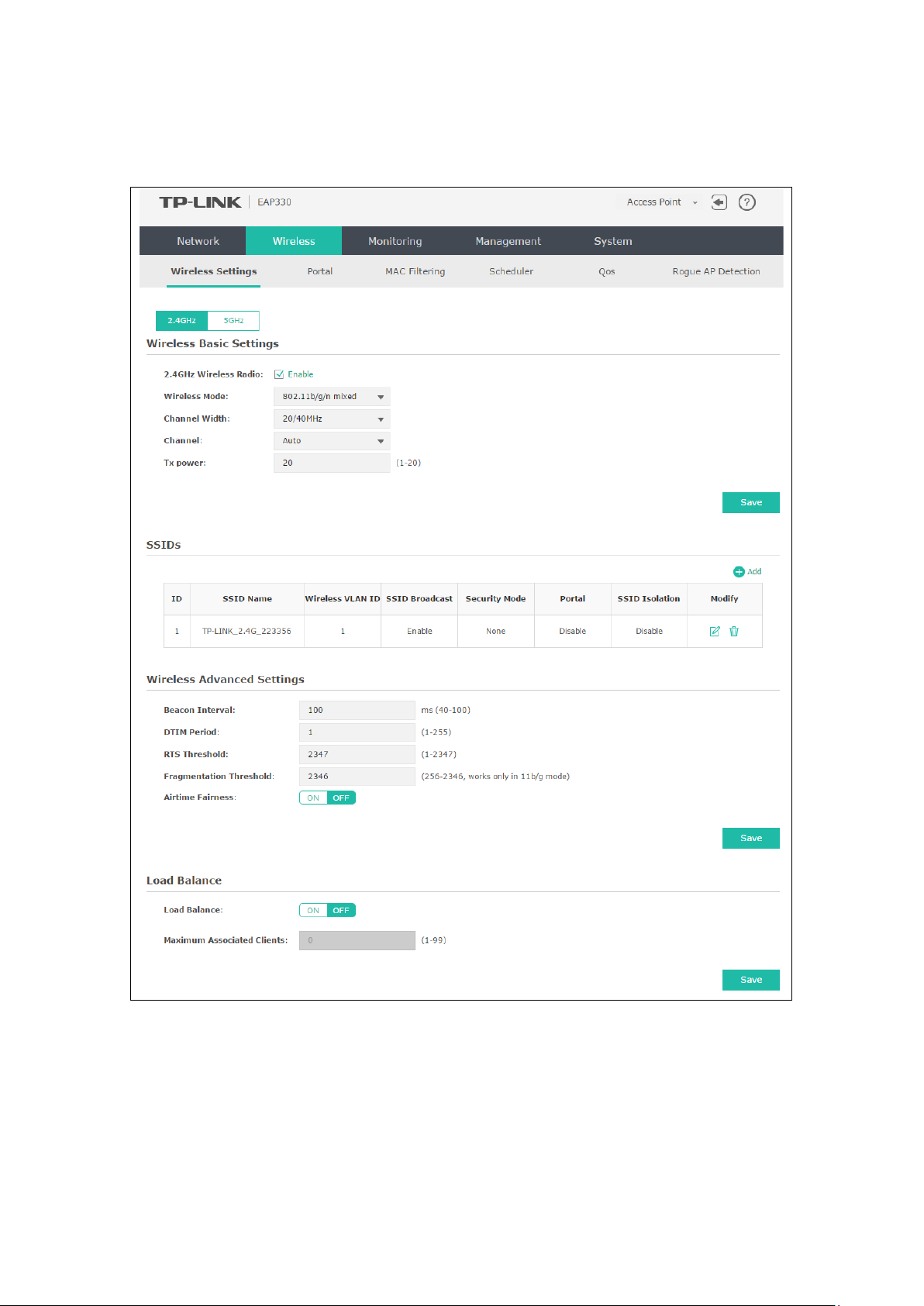
5.1 Wireless Settings
Following is the page of Wireless Settings.
Figure 5-2 Wireless Settings Page
9
Page 16
ptions include 20MHz, 40MHz and 20/40MHz (this device
can increase wireless throughput. However, users may choose lower
To avoid interference from overlapping channels occupied by other
roceed to the following chapter for information on configuring the wireless network of the EAP.
TIPS:
P
The configuring information of 2.4GHz is taken as the example.
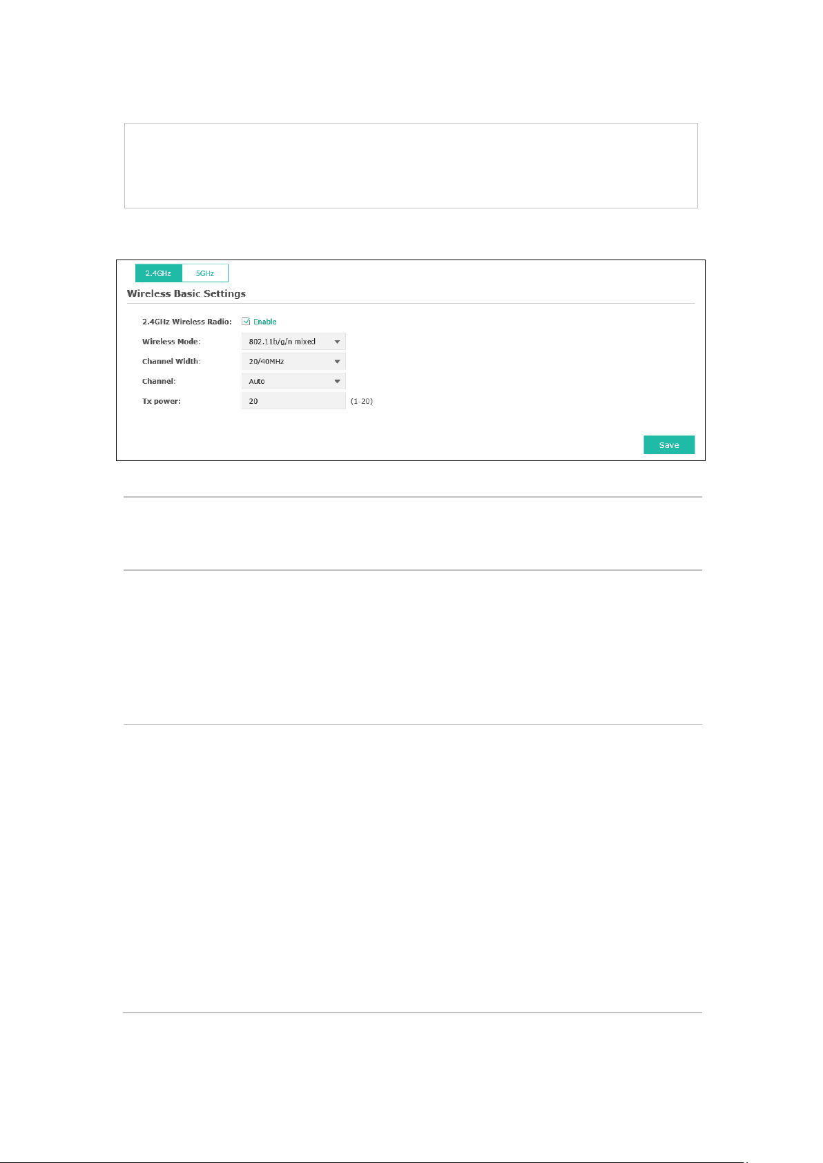
5.1.1 Wireless Basic Settings
Figure 5-3 Wireless Basic Settings
2.4GHz Wireless
Radio/5GHz
Wireless Radio:
Wireless Mode:
Channel Width:
Check the box to enable the Wireless Radio.
Select the protocol standard for the wireless network.
Wireless network created by the EAP is able to operate in the 2.4GHz and 5GHz
frequency The EAP supports 802.11b/g/n, 802.11b/g, 802.11n standards in the
2.4GHz mode and 802.11a/n/ac, 802.11n/ac, 802.11ac standards in the 5GHz
mode. It is recommended to select 802.11b/g/n (2.4GHz) and 802.11a/n/ac
(5GHz), in which way clients supporting any one of these modes can access
your wireless network.
Select the channel width of this device.
For 2.4Ghz, the o
automatically selects 20MHz or 40MHz, and 20MHz will be used if 40MHz is not
available), and for 5Ghz, include 20MHz, 40MHz, 80MHz and 20/40/80MHz.
According to IEEE 802.11 standard, using a channel width of 40MHz or 80MHz
bandwidth due to the following reasons:
1. To increase the available number of channels within the limited total
bandwidth.
2.
devices in the environment.
3. Lower bandwidth can concentrate higher transmit power, increasing
stability of wireless links over long distances.
10
Page 17

elect the channel used by this device to improve wireless performance.
n needed may cause interference to
neighborhood. Also it consumes more power and will reduce longevity of the
to achieve the best
Channel:
Tx power:
S
1/2412MHz means the channel is 1 and the frequency is 2412MHz.
Enter the transmit power value. By default, the value is 20.
If the maximum transmit power is set to be larger than local regulation allows,
the maximum Tx power regulated will be applied in actual situation.
NOTE: In most cases, it is unnecessary to select maximum transmit power.
Selecting larger transmit power tha
device. Select a certain transmit power is enough
performance.
5.1.2 SSIDs
SSIDs can work together with switches supporting 802.1Q VLAN. The EAP can build up to eight
virtual wireless networks per radio for users to access. At the same time, it adds different VLAN
tags to the clients which connect to the corresponding wireless network. It supports maximum
8 VLANs per radio. The clients in different VLAN cannot directly communicate with each other.
Clients connected to the device via cable do not belong to any VLAN. Thus wired client can
communicate with all the wireless clients despite the VLAN settings.
Click in the Modify column, the following content will be shown.
Figure 5-4 SSIDs
SSID Name:
Wireless VLAN
ID:
Click to add up to 8 wireless networks per radio.
Enter up to 32 characters as the SSID name.
Set a VLAN ID (ranges from 1 to 4094) for the wireless network. Wireless networks
with the same VLAN ID are grouped to a VLAN.
11
Page 18

, AP will broadcast its SSID to hosts in the surrounding
his device
for the clients who want to access the
After enabling SSID Isolation, the devices connected in the same SSID cannot
SSID
Broadcast:
Security Mode:
Portal:
SSID Isolation:
Modify:
Enable this function
environment, as thus hosts can find the wireless network identified by this SSID. If
SSID Broadcast is not enabled, hosts must enter the AP’s SSID manually to connect
to this AP.
Select the security mode of the wireless network. For the security of wireless
network, you are suggested to encrypt your wireless network. T
provides three security modes: WPA-Enterprise, WPA-PSK (WPA Pre-Shared Key)
and WEP (Wired Equivalent Privacy). WPA-PSK is recommended. Settings vary in
different security modes as the details are in the following introduction. Select
None and the hosts can access the wireless network without password.
Portal provides authentication service
wireless local area network. For more information, refer to 5.2 Portal. After Portal
is enabled, the configurations in 5.2 Portal will be applied.
communicate with each other.
Click to open the page to edit the parameters of SSID.
Click to delete the SSID.
Following is the detailed introduction of security mode: WEP, WPA-Enterprise and WPA-PSK.
WEP
WEP (Wired Equivalent Privacy), based on the IEEE 802.11 standard, is less safe than WPAEnterprise or WPA-PSK.
NOTE:
WEP is not supported in 802.11n mode. If WEP is applied in 802.11n mode, the clients may not be
able to access the wireless network. If WEP is applied in 11b/g/n mode (in the 2.4GHz frequency
band) or 11a/n (in the 5GHz frequency band), the device may work at a low transmission rate.
Figure 5-5 Security Mode_WEP
Type:
Select the authentication type for WEP.
Auto: The default setting is Auto, which can select Open System or Shared Key
automatically based on the wireless station's capability and request.
12
Page 19

Open System: After you select Open System, clients can pass the
the authentication, or it cannot associate with the wireless network or
Hexadecimal format stands for any combination of
authentication and associate with the wireless network without password.
However, correct password is necessary for data transmission.
Shared Key: After you select Shared Key, clients has to input password to pass
transmit data.
Key Selected:
Wep Key
Format:
You can configure four keys in advance and select one as the present valid key.
Select ASCII or Hexadecimal as the WEP key format.
ASCII: ASCII format stands for any combination of keyboard characters in the
specified length.
Hexadecimal:
hexadecimal digits (0-9, a-f, A-F) in the specified length.
Key Type:
Select the WEP key length (64-bit, or 128-bit) for encryption.
64-bit: You can enter 10 hexadecimal digits (any combination of 0-9, a-f, A-F
without null key) or 5 ASCII characters.
128-bit: You can enter 26 hexadecimal digits (any combination of 0-9, a-f, A-
F without null key) or 13 ASCII characters.
Key Value:
WPA-Enterprise
Enter the key value.
Based on RADIUS server, WPA -Enterprise can generate different passwords for different users and
it is much safer than WPA-PSK. However, it costs much to maintain and is more suitable for
enterprise users. At present, WPA-Enterprise has two versions: WPA-PSK and WPA2-PSK.
Figure 5-6 Security Mode_WPA-Enterprise
Version:
Select one of the following versions:
Auto: Select WPA-PSK or WPA2-PSK automatically based on the client
device's capability and request.
WPA-PSK: Pre-shared key of WPA.
WPA2-PSK: Pre-shared key of WPA2.
13
Page 20

is Auto, which can select TKIP (Temporal Key Integrity Protocol) or AES
not be able to access the wireless network of the EAP. If TKIP is applied in 11b/g/n
Encryption: Select the encryption type, including Auto, TKIP, and AES. The default setting
(Advanced Encryption Standard) automatically based on the client device's
capability and request. AES is more secure than TKIP and TKIP is not supported
in 802.11n mode. It is recommended to select AES as the encryption type.
RADIUS Server
Enter the IP address/port of the RADIUS server.
IP/Port:
RADIUS
Enter the shared secret of RADIUS server to access the RADIUS server.
Password:
Group Key
Update period:
Specify the group key update period in seconds. The value can be either 0 or
30-8640000 seconds.
NOTE:
Encryption type TKIP is not supported in 802.11n mode. If TKIP is applied in 802.11n mode, the
clients may
mode (in the 2.4GHz frequency band) or 11a/n (in the 5GHz frequency band), the device may work
at a low transmission rate.
WPA-PSK
Based on pre-shared key, security mode WPA-PSK is characterized by high security and simple
configuration, which suits for common households and small business. WPA-PSK has two
versions: WPA-PSK and WPA2-PSK.
Figure 5-7 Security Mode_WPA-PSK
Version:
Auto: Select WPA or WPA2 automatically based on the wireless station's
capability and request.
WPA-PSK: Pre-shared key of WPA.
WPA2-PSK: Pre-shared key of WPA2.
14
Page 21
automatically based on the wireless station's capability
with ASCII or Hexadecimal
For ASCII, the length should be between 8 and 63 characters with
Interval value determines the time
, the access point will release the buffered
Encryption: Select the encryption type, including Auto, TKIP, and AES. The default setting is
Auto, which can select TKIP (Temporal Key Integrity Protocol) or AES (Advanced
Encryption Standard)
and request. AES is more secure than TKIP and TKIP is not supported in 802.11n
mode. It is recommended to select AES as the encryption type.
Wireless
Password:
Group Key
Update Period:
Configure the WPA-PSK/WPA2-PSK password
characters.
combination of numbers, letters (case-sensitive) and common punctuations. For
Hexadecimal, the length should be 64 characters (case-insensitive, 0-9, a-f, A-F).
Specify the group key update period in seconds. The value can be either 0 or at
least 30. 0 means no update.
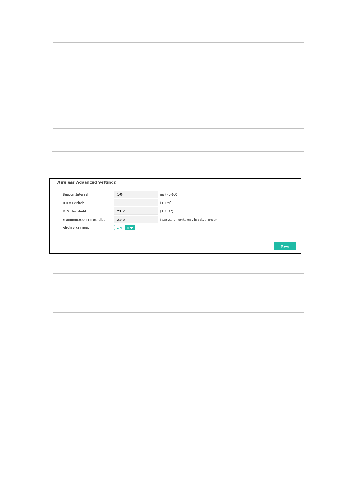
5.1.3 Wireless Advanced Settings
Figure 5-8 Wireless Advanced Settings
Beacon
Interval:
DTIM Period:
RTS Threshold:
Beacons are transmitted periodically by the device to announce the presence of a
wireless network for the clients. Beacon
interval of the beacons sent by the device. You can specify a value from 40 to 100.
The default value is 100 milliseconds.
This value indicates the number of beacon intervals between successive Delivery
Traffic Indication Messages (DTIMs) and this number is included in each Beacon
frame. A DTIM is contained in Beacon frames to indicate whether the access point
has buffered broadcast and/or multicast data for the client devices. Following a
Beacon frame containing a DTIM
broadcast and/or multicast data, if any exists. You can specify the value between
1-255 Beacon Intervals. The default value is 1, indicating the DTIM Period is the
same as Beacon Interval. An excessive DTIM period may reduce the performance
of multicast applications. It is recommended to keep it by default.
When the RTS threshold is activated, all the stations and APs follow the Request
to Send (RTS) protocol. When the station is to send packets, it will send a RTS to
AP to inform the AP that it will send data. After receiving the RTS, the AP notices
other stations in the same wireless network to delay their transmitting of data. At
the same time, the AP inform the requesting station to send data. The value range
15
Page 22

is from 1 to 2347 bytes. The default value is 2347, which means that RTS is
disabled.
than the fragmentation threshold, the packet will be fragmented into several
packets. Too low fragmentation threshold may result in poor wireless
Airtime Fairness is a feature that boost the overall network performance by
speed devices can be slow from either long physical distance, weak signal
away the monopoly in network time by the slower device (making the slower
Fragmentation
Threshold:
Airtime
Fairness:
Specify the fragmentation threshold for packets. If the size of the packet is larger
performance caused by the excessive packets. The recommended and default
value is 2346 bytes.
sacrifice a little bit of network time on your slowest devices. The relatively “slow”
wifi
strength, or simply being a legacy device with older technology. The setting takes
device even slower), dedicate and shift those processing time to the faster device
to achieve better overall network performance.
5.1.4 Load Balance
By restricting the maximum number of clients accessing the EAPs, Load Balance helps to achieve
rational use of network resources.
Figure 5-9 Load Balance
Load Balance: Disable by default. Click ON to enable the function. After enabling it, you
can set a number for maximum associated clients to control the wireless
access.
Maximum
Associated Clients:
Enter the number of clients to be allowed for connection to the EAP. The
value ranges from 1 to 99.
5.2 Portal
Portal authentication enhances the network security by providing authentication service to the
clients that just need temporary access to the wireless network. Such clients have to log into a
web page to establish verification, after which they will access the network as guests. What's
more, you can customize the authentication login page and specify a URL which the newly
authenticated clients will be redirected to. Please refer to Portal Configuration or
Authentication Policy according to your need.
Free
16
Page 23

Following is the page of Portal.
Figure 5-10 Portal Page
NOTE:
To apply Portal in a wireless network, please go to Wireless→Wireless Settings→SSIDs to enable
Portal of a selected SSID.
5.2.1 Portal Configuration
Three authentication types are available: No Authentication, Local Password and External
RADIUS Server.
17
Page 24

the device keeps the authentication session open with the
To reopen the session, the client needs to log in the web
authentication page and enter the user name and password again once
No Authentication:Users are required to finish only two steps: agree with the user protocol and
click the Login button.
Local Password:Users are required to enter the preset password, which are saved in the EAP.
External RADIUS Server:Users are required to enter the preset user name and password, which
are saved in the database of the RADIUS server. The RADIUS server acts as the authentication
server, which allows you to set different usernames and passwords for different users.
Refer to the following content to configure Portal based on actual network situations.
No Authentication
Figure 5-11 Portal Configuration_No Authentication
Authentication
Select No Authentication.
Type:
Authentication
Timeout:
After successful verification, an authentication session is established.
Authentication Timeout decides the active time of the session. Within the
active time,
associated client.
authentication timeout is reached.
By default, authentication timeout is eight hours. Select Custom from the
drop-down list to customize the parameter.
Redirect:
Disable by default. Redirect specifies that the portal should redirect the newly
authenticated clients to the configured URL.
18
Page 25

Redirect URL:
Portal
Customization:
If you enable the Redirect function, please enter the URL that a newly
authenticated client will be directed to.
Select Local Web Portal, the authentication login page will be provided by the
built-in web server.
The page configured below will be presented to users as the login page. Words
can be filled in Input Box 1 and Input Box 2.
Enter up to 31 characters as the title of the authentication login page in Input
Box 1, like “Guest Portal of TP-LINK”.
Enter the terms presented to users in Input Box 2. The terms can be 1 to 1023
characters long.
19
Page 26

Local Password
Figure 5-12 Portal Configuration_Local Password
Authentication Type: Select Local Password.
Password:
Enter the password for local authentication.
Please refer to No Authentication to configure Authentication Timeout, Redirect, Redirect
URL, and Portal Customization.
External RADIUS Server
External RADIUS Server provides two types of portal customization: Local Web Portal and
External Web Portal. The authentication login page of Local Web Portal is provided by the builtin web server of the EAP, as Figure 5-13 shown. The authentication login page of External Web
Portal is provided by external web server, as Figure 5-14 shown.
20
Page 27

1. Local Web Portal
Figure 5-13 Portal Configuration_External RADIUS Server_Local Web Portal
Authentication Type: Select External RADIUS Server.
RADIUS Server IP:
Port:
RADIUS Password:
Enter the IP address of the RADIUS server.
Enter the port for authentication service.
Enter the shared secret of RADIUS server to log in to the RADIUS server.
Please refer to No Authentication to configure Authentication Timeout, Redirect, Redirect
URL, and Portal Customization.
21
Page 28

2. External Web Portal
Figure 5-14 Portal Configuration_External RADIUS Server_External Web Portal
Authentication Type: Select External RADIUS Server.
RADIUS Server IP:
Port:
RADIUS Password:
Portal Customization: Select External Web Portal.
External Web Portal
URL:
Enter the IP address of the RADIUS server.
Enter the port for authentication service.
Enter the shared secret of RADIUS server to log in to the RADIUS server.
Enter the authentication login page’s URL, which is provided by the
external web server.
Please refer to No Authentication to configure Authentication Timeout, Redirect and Redirect
URL.
5.2.2 Free Authentication Policy
Free Authentication Policy allows clients to access network resources for free. On the lower part
of the Portal page you can configure and view free authentication policies.
Figure 5-15 Free Authentication Policy
22
Page 29

Click to add a new authentication policy and configure its parameters.
Figure 5-16 Configure Free Authentication Policy
Policy Name:
Source IP
Range:
Destination IP
Range:
Source MAC:
Destination
Port:
Status:
Enter a policy name.
Enter the source IP address and subnet mask of the clients who can enjoy the
free authentication policy. Leaving the field empty means all IP addresses can
access the specific resources.
Enter the destination IP address and subnet mask for free authentication policy.
Leaving the field empty means all IP addresses can be visited. When External
Radius Server is configured and External Web Portal is selected, please set
the IP address and subnet mask of your external web server as the Destination
IP Range.
Enter the source MAC address of the clients who can enjoy the free
authentication policy. Leaving the field empty means all MAC addresses can
access the specific resources.
Enter the destination port for free authentication policy. Leaving the field
empty means all ports can be accessed.
Check the box to enable the policy.
23
Page 30

Click the button OK in Figure 5-16 and the policy is successfully added as Figure 5-17 shows.
Figure 5-17 Add Free Authentication Policy
Here is the explanation of Figure 5-17: The policy name is Policy 1. Clients with IP address range
192.168.2.0/24 are able to visit IP range 10.10.10.0/24. Policy 1 is enabled.
Click to edit the policy. Click to delete the policy.
5.3 MAC Filtering
MAC Filtering uses MAC addresses to determine whether one host can access the wireless
network. Thereby it can effectively control the user access to the wireless network.
Figure 5-18 MAC Filtering Page
24
Page 31

Settings
Enable MAC Filtering:
Station MAC Group
Check the box to enable MAC Filtering.
Follow the steps below to add MAC groups.
Step 1:
Click , two tables will be shown.
Figure 5-19 Station MAC Group
Step 2:
Click and fill in a name for the MAC group.
Figure 5-20 Add a Group
Step 3:
Select one MAC group, click and input the MAC address you want to
organize into this group.
25
Page 32

Figure 5-21 Add a Group Member
Click in Modify column to edit the MAC group name or MAC address. Click to delete the
MAC group or group member.
MAC Filtering Association
Figure 5-22 MAC Filtering Association
SSID Name:
Band:
MAC Group Name:
Displays the SSID of the wireless network.
Displays the frequency band the wireless network operates at.
Select a MAC group from the drop-down list to allow or deny its members
to access the wireless network.
Action:
Allow: Allow the access of the stations specified in the MAC group.
Deny: Deny the access of the stations specified in the MAC group.
5.4 Scheduler
Scheduler allows you to configure rules with specific time interval for radios to operate, which
automates the enabling or disabling of the radio.
26
Page 33

Figure 5-23 Scheduler Page
Settings
Scheduler:
Check the box to enable Scheduler.
Association Mode: Select Associated with SSID/AP, you can perform configurations on the
SSIDs/AP. The display of Scheduler Association is based on your option
here.
Scheduler Profile Configuration
Follow the steps below to add rules.
27
Page 34

Step 1:
Click , two tables will be shown.
Figure 5-24 Scheduler Profile Configuration
Step 2:
Click and input a profile name for the rule.
Figure 5-25 Add a Profile
Step 3:
Select one profile, and click and configure the recurring schedule for the rule.
Figure 5-26 Add a Rule
28
Page 35

the wireless network during the time
Scheduler Association
This zone will display different contents based on your selection of association mode in Settings.
1. Associated with SSID
Figure 5-27 Scheduler Association_Associated with SSID
SSID Name:
Band:
Profile Name:
Displays the SSID of the standalone AP.
Displays the frequency band which the wireless network operates at.
Select a profile name from the drop-down list. Profile name is configured in
Scheduler Profile Configuration.
Action: Select Radio On/Off to turn on/off the wireless network during the time
interval set for the profile.
2. Associated with AP
Figure 5-28 Scheduler Association_Associated with AP
AP:
Displays the name of the device.
AP MAC:
Profile Name:
Displays the MAC address of the device.
Select a profile name from the drop-down list. Profile name is configured in
Scheduler Profile Configuration.
Action: Select Radio On/Off to turn on/off
interval set for the profile.
29
Page 36

5.5 QoS
The EAP supports Quality of Service (QoS) to prioritize voice and video traffic over other traffic
types. In normal use, we recommend you keep the default values for the EAP devices and station
EDCA (Enhanced Distributed Channel Access).
2.4GHz/5GHz
Wi-Fi Multimedia
(WMM):
Figure 5-29 QoS Page
Select the 2.4GHz or 5GHz to show and configure the setting of 2.4GHz or
5GHz.
By default, WMM is enabled. After WMM is enabled, the device has the QoS
function to guarantee the transmission of audio and video packets with high
priority.
30
Page 37

The upper limit (in milliseconds) for the doubling of the random backoff
ues until either the data frame is sent or the
multiple frames
5.5.1 AP EDCA Parameters
AP Enhanced Distributed Channel Access (EDCA) parameters affect traffic flowing from the EAP
device to the client station.
Figure 5-30 AP EDCA Parameters
Queue:
Arbitration InterFrame Space:
Minimum
Contention
Window:
Queue displays the transmission queue. By default, the priority from high to
low is Data 0, Data 1, Data 2, and Data 3. The priority may be changed if you
reset the EDCA parameters.
Data 0 (Voice)— Highest priority queue, minimum delay. Time-sensitive
data such as VoIP and streaming media are automatically sent to this queue.
Data 1 (Video)—High priority queue, minimum delay. Time-sensitive video
data is automatically sent to this queue.
Data 2 (Best Effort) — Medium priority queue, medium throughput and
delay. Most traditional IP data is sent to this queue.
Data 3 (Background)—Lowest priority queue, high throughput. Bulk data
that requires maximum throughput and is not time-sensitive is sent to this
queue (FTP data, for example).
A wait time for data frames. The wait time is measured in slots. Valid values
for Arbitration Inter-Frame Space are from 1 to 15.
A list to the algorithm that determines the initial random backoff wait time
(window) for retry of a transmission.
This value can not be higher than the value for the Maximum Contention
Window.
Maximum
Contention
Window:
Maximum Burst The Maximum Burst is a AP EDCA parameter that applies only to traffic
value. This doubling contin
Maximum Contention Window size is reached.
This value must be higher than the value for the Minimum Contention
Window.
flowing from the EAP devices to the client station. This value specifies (in
milliseconds) the maximum burst length allowed for packet bursts on the
wireless network. A packet burst is a collection of
transmitted without header information. The decreased overhead results in
higher throughput and better performance.
The valid values are multiples of 32 between 0 and 8192.
31
Page 38

:
:
A wait time for data frames. The wait time is measured in slots. Valid
:
A list to the algorithm that determines the initial random backoff wait
(window) for retry of a transmission. This value can not be higher
:
5.5.2 Station EDCA Parameters
Station EDCA parameters affect traffic flowing from the client station to the EAP device.
Figure 5-31 Station EDCA Parameters
Queue
Arbitration Inter-
Frame Space
Minimum Contention
Window
Maximum
Contention
Window
Queue displays the transmission queue. By default, the priority from high
to low is Data 0, Data 1, Data 2, and Data 3. The priority may be changed
if you reset the EDCA parameters.
Data 0 (Voice)—Highest priority queue, minimum delay. Time-sensitive
data such as VoIP and streaming media are automatically sent to this
queue.
Data 1 (Video)— High priority queue, minimum delay. Time-sensitive
video data is automatically sent to this queue.
Data 2 (Best Effort)—Medium priority queue, medium throughput and
delay. Most traditional IP data is sent to this queue.
Data 3 (Background)— Lowest priority queue, high throughput. Bulk
data that requires maximum throughput and is not time-sensitive is sent
to this queue (FTP data, for example).
values for Arbitration Inter-Frame Space are from 0 to 15.
time
than the value for the Maximum Contention Window.
The upper limit (in milliseconds) for the doubling of the random backoff
value. This doubling continues until either the data frame is sent or the
Maximum Contention Window size is reached.
This value must be higher than the value for the Minimum Contention
Window.
32
Page 39

from the client station to the EAP device. The Transmission
:
:
TXOP Limit:
No
Acknowledgement
Unscheduled
Automatic Power
Save Delivery
The TXOP Limit is a station EDCA parameter and only applies to traffic
flowing
Opportunity (TXOP) is an interval of time, in milliseconds, when a WME
client station has the right to initiate transmissions onto the wireless
medium (WM) towards the EAP device.
The valid values are multiples of 32 between 0 and 8192.
Select Enable to specify that the EAP device should not acknowledge
frames with QosNoAck as the service class value. By default, it is disabled.
Select Enable to enable APSD, which is a power management method.
APSD is recommended if VoIP phones access the network through the
EAP device. By default, it is enabled.
5.6 Rogue AP Detection
A Rogue AP is an access point that has been installed on a secure network without explicit
authorization from a system administrator.
The EAP device can scan all channels to detect all APs in the vicinity of the network. If rogue APs
are detected, they are shown on the Detected Rogue AP List. If an AP listed as a rogue is
legitimate, you can add it to the Trusted AP List.
33
Page 40

Figure 5-32 Rogue AP Detection Page
5.6.1 Settings
Figure 5-33 Enable Rogue AP Detection
Rogue AP Detection: Check the box to enable Rogue AP Detection, then click Save.
5.6.2 Detected Rogue AP List
Information about the detected rogue APs is displayed in the list. By default, the status of the
detected rogue AP is unknown. You can click Known in Action column to move the AP to the
Trusted AP List.
34
Page 41

Beacon frames are transmitted by an AP at regular intervals to announce the
Figure 5-34 Detected Rogue AP List
Action: Click Known to move the AP to the Trusted AP List. After the configurations are
MAC:
SSID:
Band:
Channel:
Security:
Beacon
Interval:
Signal:
Click to scan rogue APs. Make sure you have enabled Rogue AP Detection and
saved the setting before you click the button.
saved, the moved AP will not be displayed in the Detected Rogue AP List.
The MAC address of the rogue AP.
The SSID of the rogue AP.
Displays the frequency band which the wireless network of the rogue AP operates
at.
The channel on which the rogue AP is currently broadcasting.
Displays the enabling or disabling of the security mode of the wireless network.
The beacon interval used by the rogue AP.
existence of the wireless network. The default behavior is to send a beacon frame
once every 100 milliseconds (or 10 per second).
The strength of the radio signal emitting from the rogue AP.
5.6.3 Trusted AP List
Information about the trusted APs is displayed in the list.
Figure 5-35 Trusted AP List
Action: Click Unknown to move the AP out of the Trusted AP List.
MAC:
The MAC address of the trusted AP.
35
Page 42

SSID:
Band:
Channel:
Security:
The SSID of the trusted AP.
Displays the frequency band which the wireless network of the trusted AP operates
at.
The channel on which the trusted AP is currently broadcasting.
Displays the enabling or disabling of the security mode of the wireless network.
5.6.4 Download/Backup Trusted AP List
You can import a list of trusted APs from a saved list which is acquired from another AP or created
from a text file. The AP whose MAC address is in the Trusted AP List will not be detected as a
rogue.
You can also backup a list and save it in your PC.
Figure 5-36 Download/Backup Trusted AP List
Save Action: Select Download (PC to AP) to import a trusted AP list to the device.
Select Backup (AP to PC) to copy the trusted AP list to your PC.
Source File
Name:
File
Management:
Click Browse and choose the path of a saved trusted AP list or to save a
trusted AP list.
Select Replace to import the list and replace the contents of the Trusted AP
List.
Select Merge to import the list and add the APs in the imported file to the
APs currently shown in the Trusted AP List
NOTE:
EAP device does not have any control over the APs in the Detected Rogue AP List.
36
Page 43

Chapter 6 Monitoring
On Monitoring page, you can monitor the network running status and statistics based on AP,
SSID and Client.
6.1 AP
AP List on the Monitoring page displays the device name, its MAC address and the number of
clients. Below the AP List the AP’s detailed information will be shown, including
Information, Wireless Settings, LAN Information, Client, LAN Traffic and Radio Traffic.
Device
6.1.1 AP List
Figure 6-1 AP Monitoring
Figure 6-2 AP List
37
Page 44

Device Name:
MAC:
Num of Clients:
Device Information
Displays the device name.
Displays the MAC address of the EAP.
Displays the number of clients connected to the EAP.
Device Name:
Device Model:
Firmware
Version:
System Time:
Uptime:
CPU0/CPU1:
Memory:
Figure 6-3 Device Information
Displays the device name.
Displays the model of the device.
Displays the firmware version of the device. If you want to upgrade the firmware,
please refer to 8.5 Firmware Upgrade
.
Displays the system time of the device. If you want to adjust the system time,
please refer to 8.2.1 Time Settings
.
Displays the time that has elapsed since the last reboot.
Displays the CPU occupancy, which helps you to preliminarily judge whether the
device functions properly.
Displays the memory usage , which helps you to preliminarily judge whether the
device functions properly.
38
Page 45

Wireless Settings
Displays the spectral width of the radio channel used by the device. If
Displays the radio standard used for operation of your device. If you
Figure 6-4 Wireless Settings
2.4GHz/5GHz
Channel/Frequency:
Choose one band to view the information about wireless setting.
Displays the channel number and the operating frequency. If you want
to change them, please refer to 5.1.1 Wireless Basic Settings
Channel Width:
you want to change it, refer to 5.1.1 Wireless Basic Settings.
IEEE802.11 Mode:
want to change it, refer to 5.1.1 Wireless Basic Settings.
Max TX Rate:
Displays the maximum data rate at which the device should transmit
wireless packets.
Transmit Power:
Displays the maximum average transmit power of the device. If you
want to change it, refer to 5.1.1 Wireless Basic Settings
LAN Information
.
.
Figure 6-5 LAN Information
MAC Address:
IP Address:
Displays the MAC address of the device.
Displays the IP address of the device.
39
Page 46

the power ratio between the received wireless signal
Displays the wireless Client Connection Quality (CCQ). CCQ refers to the ratio of
current effective transmission bandwidth and the theoretically maximum
Subnet Mask:
LAN Port1/ LAN
Port2:
Client
MAC:
SSID:
SNR(dB):
Displays the subnet mask of the device.
Displays the maximum transmission rate and duplex mode (half-duplex or
full-duplex) of the port.
Figure 6-6 Client
Displays the MAC address of the client of the AP selected in AP List.
Displays the SSID the client is connected to.
Signal to Noise Ratio,
strength and the environmental noise strength. The bigger the value of SNR is, the
better network performance the device provides.
CCQ(%):
available bandwidth. CCQ reflects the actual link condition.
Rate(Mbps):
Down(Byte):
Up(Byte):
Active Time:
LAN Traffic
Displays the data rate at which the client transmits wireless packets.
Displays the throughput of the downstream data.
Displays the throughput of the upstream data.
Displays the amount of time the client has been connected to the device.
Click LAN Traffic and you can monitor the data transmission status of the LAN port.
Figure 6-7 LAN Traffic
40
Page 47

Rx/Tx Packets:
Rx/Tx Bytes:
Rx/Tx Dropped
Packets:
Rx/Tx Errors:
Radio Traffic
Displays the total amount of packets received/sent on the LAN port.
Displays the total amount of data (in bytes) received/sent on the LAN port.
Displays the total amount of dropped packets received/sent on the LAN
port.
Displays the total amount of error packets received/sent on the LAN port.
Click Radio Traffic and you can monitor the data transmission status of the wireless network.
2.4GHz/5GHz:
Rx/Tx Packets:
Rx/Tx Bytes:
Rx/Tx Dropped
Packets:
Rx/Tx Errors:
Figure 6-8 Radio Traffic
Choose one band to show the information about radio traffic.
Displays the total amount of packets received/sent by the wireless network.
Displays the total amount of data (in bytes) received/sent by the wireless
network.
Displays the total amount of dropped packets received/sent by the wireless
network.
Displays the total amount of error packets received/sent by the wireless
network.
41
Page 48

6.2 SSID
isplays the enabling or disabling of Portal. If you want to modify it, please
Figure 6-9 SSID Monitoring
6.2.1 SSID List
In SSID List you can monitor the related parameters of the wireless network.
Figure 6-10 SSID List
SSID Name:
VLAN ID:
Num of Clients:
SSID Broadcast:
Displays the SSID name. If you want to modify it, please refer to 5.1.2 SSIDs
Displays the VLAN which the SSID belongs to. If you want to change the VLAN
ID, please refer to 5.1.2 SSIDs
Displays the number of clients connected to the SSID. If you want to get more
information about these clients, please refer to 5.1.2 SSIDs
Displays the enabling or disabling of SSID broadcast. If you want to modify it,
please refer to 5.1.2 SSIDs
.
.
.
.
Band:
Security:
Portal:
Displays the frequency band the wireless network is operating at.
Displays the security mode the wireless network is applying. If you want to
modify it, please refer to 5.1.2 SSIDs
D
refer to 5.1.2 SSIDs.
42
.
Page 49

isplays the enabling or disabling of MAC Filtering. If you want to modify it,
isplays the enabling or disabling of SSID Isolation. If you want to modify it,
MAC Filtering:
Isolation:
Down(Byte):
Up(Byte):
D
please refer to 5.1.2 SSIDs.
D
please refer to 5.1.2 SSIDs.
Displays the throughput of the downstream data.
Displays the throughput of the upstream data.
6.3 Client
From User List, you can monitor the status of all the clients connected to the EAP including those
who are authenticated.
6.3.1 User List
MAC:
Band:
Displays the MAC address of the client.
Displays the band the client is in.
Figure 6-11 Client Monitoring
Figure 6-12 User List
43
Page 50

the power ratio between the received wireless signal
current effective transmission bandwidth and the theoretically maximum
the power ratio between the received wireless signal
refers to the ratio of current effective transmission bandwidth and the
theoretically maximum available bandwidth. CCQ reflects the actual link
Access Point:
SSID:
SNR(dB):
CCQ(%):
Rate(Mbps):
Down(Byte):
Up(Byte):
Active Time:
Displays the name of the device to which the client is connected.
Displays the SSID the client is connected to.
Signal to Noise Ratio,
strength and the environmental noise strength. The bigger the value of SNR, the
better network performance the device provides.
Displays the wireless Client Connection Quality (CCQ). CCQ refers to the ratio of
available bandwidth. CCQ reflects the actual link condition.
Displays the data rate at which the client transmits wireless packets.
Displays the throughput of the downstream data.
Displays the throughput of the upstream data.
Displays the amount of time the client has been connected to the device.
6.3.2 Portal Authenticated Guest
The Portal Authenticated Guest displays information about clients that have set up valid
authentication.
MAC:
Band:
Access Point:
SSID:
SNR(dB):
Figure 6-13 Portal Authenticated Guest
Displays the MAC address of the authenticated client.
Displays the band the authenticated client is in.
Displays the name of the device to which the authenticated client is connected
Displays the SSID the authenticated client is connected to.
Signal to Noise Ratio,
strength and the environmental noise strength. The bigger the value of SNR, the
better network performance the device provides.
CCQ(%):
Displays the Client Connection Quality (CCQ) of the authenticated client. CCQ
condition.
44
Page 51

Rate(Mbps):
Displays the data rate at which the authenticated client transmits wireless
packets.
Down(Byte):
Up(Byte):
Active Time:
Displays the throughput of the downstream data.
Displays the throughput of the upstream data.
Displays the amount of time the client has been authenticated on the root AP.
Action: Click Unauthorize to stop giving authorization to the clients connected to the
wireless network.
45
Page 52

Chapter 7 Management
Management page is mainly used for device management and maintenance.
7.1 System Log
System log records information about hardware, software as well as system issues and monitors
system events. With the help of system log, you can get informed of system running status and
detect the reasons for failure.
Following is the page of System Log.
Figure 7-1 System Log Page
7.1.1 Log List
From Log List you can view detailed information about hardware, software, system issues and so
on.
46
Page 53

Figure 7-2 Log List
7.1.2 Log Settings
You can choose the way to receive system logs in Log Settings zone, where these parameters
can be configured: Enable Auto Mail, Enable Server and Enable Nvram
Figure 7-3 Log Settings
Enable Auto Mail
.
If Auto Mail Feature is enabled, system logs will be sent to a mailbox. The following content will
be shown.
From:
To:
Figure 7-4 Enable Auto Mail
Enter the sender’s email address.
Enter the recipient’s email address, which will receive the system logs.
47
Page 54

SMTP Server:
Enable
Authentication:
Time Mode:
Enter the IP address of the SMTP server.
Generally users are required to log in to the SMTP server by entering user
name and password.
User Name: Enter the sender’s email address.
Password: Enter the password of the sender’s email address.
Confirm Password: Enter the password again for confirmation.
System logs can be sent at specific time or time interval.
Fixation Time: Set a fixed time, for example, 15:00. The recipient will
receive the system logs sent by the device at 15:00 every day.
Period Time: Set a time interval, for example, 5 hours. The recipient will
receive the system logs sent by the device every 5 hours.
Enable Server
System logs can also be sent to a server. After Enable Server is enabled, the following content
will be shown.
Figure 7-5 Enable Server
System Log Server IP:
System Log Server Port:
Enable Nvram
Enter the IP address of the remote server.
Enter the port of the remote server.
By default, Nvram is disabled. Check the box to enable Nvram, system logs will be saved after
power supply is cut.
Nvram (Non-volatile Random Access Memory) is a RAM that can still save data even if a device is
power off. All TP-LINK EAPs are equipped with Nvram. With this option enabled, the Nvram
feature can help reserve the system logs when an EAP device is power off.
7.1.3 Backup Log
You can save the current system log to a file. Following is the page of Backup Log.
48
Page 55

ut time, the system will log out automatically. Please
Figure 7-6 Backup Log Page
7.2 Web Server
You can log in web management interface, thereby manage and maintain the device.
Following is the page of Web Server.
Figure 7-7 Web Server Page
HTTPS:
Secure Server
Port:
Server Port:
Session
Timeout:
HTTPS (Hypertext Transfer Protocol Secure) is enabled by default.
Designate a secure server port for web server in HTTPS mode. By default the
port is 443.
Designate a server port for web server in HTTP mode. By default the port is 80.
Set the session timeout time. If you do nothing with the web management
page within the timeo
login again if you want to go back to web management page.
7.3 Management Access
Management Access Control allows you to configure up to four MAC addresses of the hosts that
are allowed to log in to the web management page of the EAP. Click Add PC’s MAC and the MAC
address of the current host will be added to MAC address list.
49
Page 56

Following is the page of Management Access.
enabled, only the PCs in MAC address list can log in the device’s web
Figure 7-8 Management Access Page
MAC
Authentication:
MAC1~MAC4:
Check the box to enable MAC Authentication. After MAC Authentication is
management page. By default this function is disabled. All PCs in LAN can log
in and manage the device.
Enter the MAC addresses of the PCs which are authorized to log in the device.
7.4 Trunk
TIPS:
Only the EAP330 has this function.
Following is the page of Trunk. By default the Trunk function is disabled.
Figure 7-9 Trunk Setting
50
Page 57

) because the
Enable:
Mode:
7.5 LED ON/OFF
Check the box to enable Trunk.
The Trunk function can bundles multiple Ethernet links into a logical link to
increase bandwidth, improve reliability, and make load balanced.
The EAP330 has two 1000Mbps Ethernet port. If the Trunk function is enabled
and the ports are in the speed of 1000Mbps Full Duplex, the whole
bandwidth of the Trunk is up to 4Gbps (2000Mbps * 2
bandwidth of each member port is 2000Mbps.
Select the applied mode of Trunk Arithmetic. The device will choose the port
to transfer the packets based on the mode of Trunk Arithmetic.
• SRC MAC + DST MAC: When this option is selected, the arithmetic will
be based on the source and destination MAC addresses of the packets.
• DST MAC: When this option is selected, the arithmetic will be based on
the destination MAC addresses of the packets.
• SRC MAC: When this option is selected, the arithmetic will be based on
the source MAC addresses of the packets.
Following is the page of LED ON/OFF. By default the LED is on.
Figure 7-10 LED ON/OFF
7.6 SSH
This device supports the SSH Server function that allows users to login and manage it through
SSH connection on the SSH client software.
SSH (Secure Shell) is a security protocol established on application and transport layers. SSHencrypted-connection is similar to a telnet connection, but essentially the old telnet remote
management method is not safe, because the password and data transmitted with plain-text
can be easily intercepted. SSH can provide information security and powerful authentication
when you login this device remotely through an insecure network environment. It can encrypt
all the transmission data and prevent the information in remote management from being leaked.
51
Page 58

Following is the page of SSH.
Figure 7-11 SSH Page
Server Port:
SSH Login:
Enter the server port. By default, it is port 22.
Check the box to enable SSH Server. By default, it is disabled.
7.7 SNMP
The device can be configured as an SNMP agent.
SNMP (Simple Network Management Protocol), the most widely applied network management
protocol, provides a management framework to monitor and maintain Internet devices. Main
functions of SNMP include monitoring network performance, detecting and analyzing network
error, configuring network devices, and so on. When networks function properly, SNMP can
perform the functions of statistics, configuration and testing. When networks have troubles,
SNMP can detect and restore these troubles.
An SNMP consists of three key components: manager, agent and MIB (Management Information
Base). SNMP manager is a client program operating at workstation, assisting network
administrators to accomplish most network device management tasks. An agent is a networkmanagement software module that resides on a managed device and responsible for receiving
and dealing with data sent by managing device. Generally the managed devices are network
devices including hosts, bridges, switches and routers. MIB is the collection of managed devices.
It defines a series of properties of the managed devices. Every SNMP agent has its own MIB.
Once the device has become an SNMP agent, it is able to receive and process request messages
from SNMP manager.
Following is the page of SNMP.
52
Page 59

The community name can be considered a group password. The default
evice's SNMP
Figure 7-12 SNMP Page
SNMP Agent:
SysContact:
SysName:
SysLocation:
Get
Community:
Get Source:
Set Community:
Enable SNMP Agent and the SNMP Agent will collect the information of this
device and respond to information requests from one or more management
systems.
Enter the textual identification of the contact person for this managed node.
Enter an administratively-assigned name for this managed node.
Enter the physical location of this managed node.
Community refers to a host group aiming at network management. Get
Community only has the read-only right of the device's SNMP information.
setting is public.
Defines the IP address (for example, 10.10.10.1) or subnet for management
systems that can serve as Get Community to read the SNMP information of this
device. The format of subnet is “IP address/bit” (such as 10.10.10.0/24). The
default is 0.0.0.0, which means all hosts can read the SNMP information of this
device.
Set Community has the read and write right of the d
information. Enter the community name that allows read/write access to the
device's SNMP information. The community name can be considered a group
password. The default setting is private.
Set Source:
Defines the IP address (for example, 10.10.10.1) or subnet for management
systems that can serve as Set Community to read and write the SNMP
information of this device. The format of subnet is “IP address/bit” (such as
10.10.10.0/24). The default is 0.0.0.0, which means all hosts can read and write
the SNMP information of this device.
53
Page 60

Defining community can allow management systems in the same community to communicate
NOTE:
with the SNMP Agent. The community name can be seen as the shared password of the network
hosts group. Thus, for the security, we suggest modifying the default community name before
enabling the SNMP Agent service. If the field of community is blank, the SNMP Agent will not
respond to any community name.
54
Page 61

System page is mainly used to configure some basic information like user account and time, and
realize functions including reboot, reset, backup, restore and upgrade the device.
8.1 User Account
You can change the username and password to protect your device from unauthorized login. We
recommend that you change the default user password on the very first system setup.
Chapter 8 System
Old User
Name/Password:
New User
Name/Password:
Confirm New
Password:
8.2 Time Settings
System time represents the device system’s notion of the passing of time. System time is the
standard time for Scheduler and other time-based functions. You can manually set the system
time, configure the system to acquire its time settings from a preconfigured NTP server or
synchronize the system time with the PC’s clock.
Figure 8-1 User Account Page
Enter the present user name and password of the admin account to get the
permission of modification.
Enter a new user name and password for the admin account. Both values are
case-sensitive, up to 64 characters and with no space.New Password must
not be "admin"
Enter the new password again.
The device supports DST (Daylight Saving Time).
55
Page 62

8.2.1 Time Settings
Click the button and the device will obtain GMT time from NTP server. IP
address of the NTP server has to be filled in.
Figure 8-2 Time Settings
Figure 8-3 Time Settings
Time zone:
Date:
Click the button and save the configuration, your PC’s time will be obtained
as the device’s system time.
Select your local time zone from the drop-down list.
Set the current date, in format MM/DD/YYYY. For example, for November
25, 2014, enter 11/25/2014 in the field.
56
Page 63

Time:
Specify the device’s time. Select the number from the drop-down list in time
format HH/MM/SS.
Primary/Secondary
NTP Server:
If you’ve selected Get GMT from an NTP server, please input the primary
NTP sever address and an alternative NTP server address.
8.2.2 Daylight Saving
Daylight Saving:
Mode:
Enable or disable the DST. DST is disabled by default.
Options include Predefined Mode, Recurring Mode and Date Mode. Please
refer to the following content for more information.
Figure 8-4 Daylight Saving
Predefined Mode
Figure 8-5 Predefined Mode
Mode: Select Predefined Mode.
Predefine Country:
Select a predefined DST configuration. Europe is the predefined country
by default.
USA: Second Sunday in March, 02:00 ~ First Sunday in November, 02:00
European: Last Sunday in March, 01:00 ~ Last Sunday in October, 01:00
Australia: First Sunday in October, 02:00 ~ First Sunday in April, 03:00
New Zealand: Last Sunday in September, 02:00 ~ First Sunday in April,
03:00
57
Page 64

Recurring Mode
Figure 8-6 Recurring Mode
Mode: Select Recurring Mode. The configuration is recurring in use.
Time Offset:
Start/End:
Date Mode
Mode: Select Date Mode.
Time Offset:
Start/End:
Specify the time adding in minutes when Daylight Saving Time comes.
Select starting time and ending time of Daylight Saving Time.
Specify the time adding in minutes when Daylight Saving Time comes.
Select starting time and ending time of Daylight Saving Time.
8.3 Reboot/Reset
Figure 8-7 Date Mode
Figure 8-8 Reboot & Reset
Click Reboot to restart the device. Click Reset to restore the device to factory default settings.
58
Page 65

8.4 Backup & Restore
Figure 8-9 Backup & Restore
You can save the current configuration of the EAP as a backup file and restore the configuration
via a backup file. Back up the settings before you upgrade the device or upload a new
configuration file can prevent it from being lost.
Restore function helps you to restore the device to previous settings by uploading a backup file.
8.5 Firmware Upgrade
Figure 8-10 Firmware Upgrade
Please log in http://www.tp-link.com/ to download the latest system file. Click Browse to choose
the firmware file. Click Upgrade to upgrade the devices.
59
Page 66

NOTE:
1. Please select the proper software version that matches your hardware to upgrade.
2. To avoid damage, please do not turn off the device while upgrading.
3. After upgrading, the device will reboot automatically.
60
Page 67

Maximum Data
Captive Portal
Appendix A: Specifications
HARDWARE FEATURES
Model EAP320 EAP330
Interface Kensington lock slot
RESET button
ETHERNET:
10/100/1000Mbps Ethernet port
(RJ-45)
CONSOLE port (RJ-45)
Power Supply PoE(802.3at-compliant, 36-57VDC,
0.7A Max) or external 12VDC/1.5A
power supply
Antenna 2*5dBi embedded(2.4GHz)
2*7dBi embedded(5GHz)
Certification CE, FCC, Wi-Fi, NCC, IC, BSMI, RoHS CE, FCC, Wi-Fi, IC, RoHS
Operating
Temperature
Operating
Humidity
WIRELESS FEATURES
Wireless
Frequency
Wi-Fi Standard IEEE 802.11b/g/n(2.4GHz), IEEE 802.1a/n/ac(5GHz)
0℃~40℃ (32℉~104℉)
10%~90% non-condensing
2.4GHz&5GHz
ETHERNET1(PoE):
10/100/1000Mbps Ethernet port
(RJ-45)
ETHERNET2: 10/100/1000Mbps
Ethernet port (RJ-45)
PoE (802.3at-compliant, 36-57VDC,
0.7A Max) or external 12VDC/2.5A
power supply
3*5dBi embedded(2.4GHz)
3*6dBi embedded(5GHz)
Rate
Multiple SSIDs Up to eight per radio
Authentication
Wireless Security WEP
Up to 1200Mbps Up to 1900Mbps
Support
WPA/WPA2-personal
WPA/WPA2-enterprise
61
 Loading...