

Toyota Tercel 1997 User Manual
BO–6
–BODY HOOD
HOOD
BO1FM–02
ADJUSTMENT
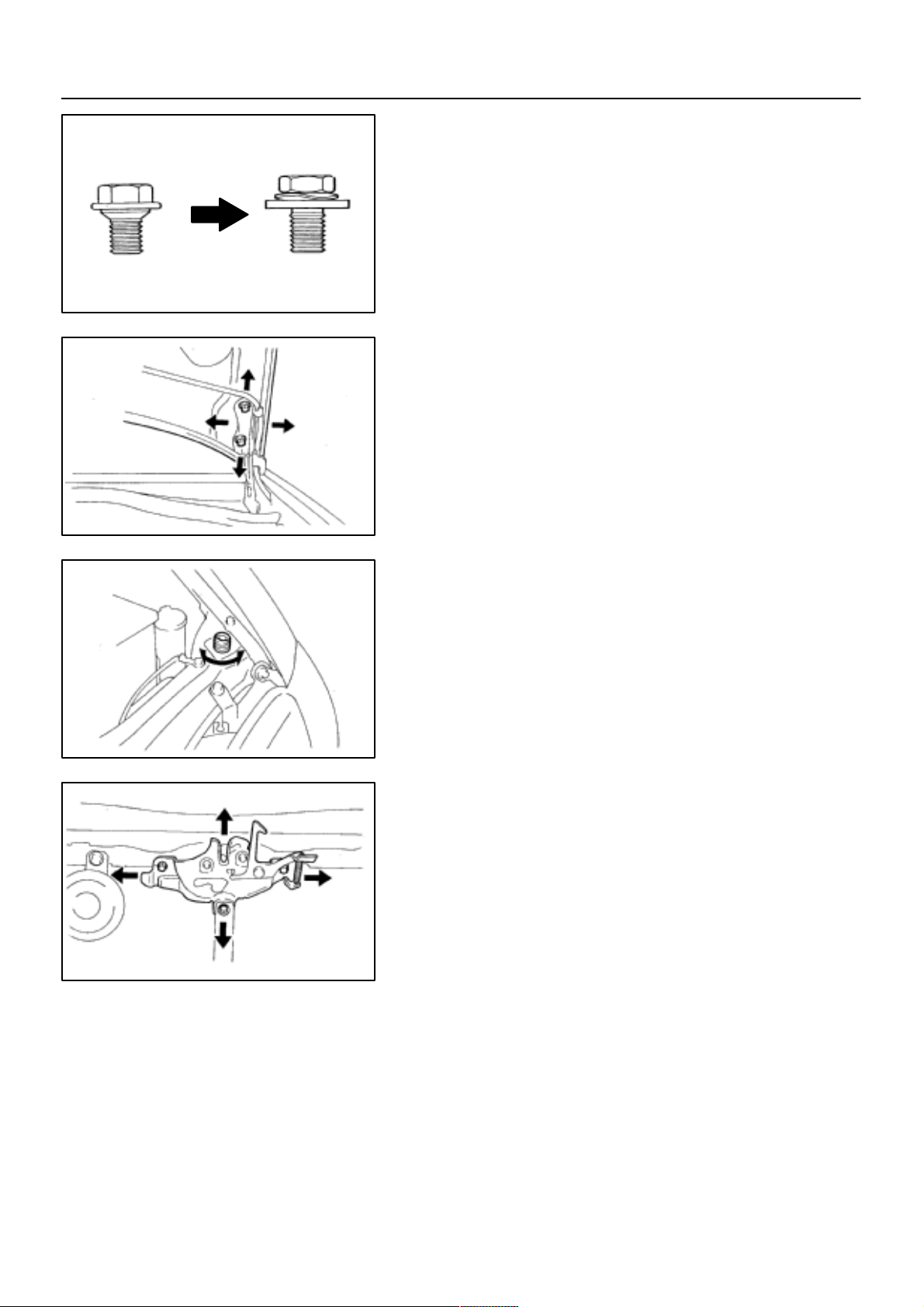
HINT:
Since the centering bolt is used as the hood hinge set bolt, the
hood cannot be adjusted with it on. Substitute the bolt with
washer for the centering bolt.
Bolt with WasherCentering Bolt
H01976
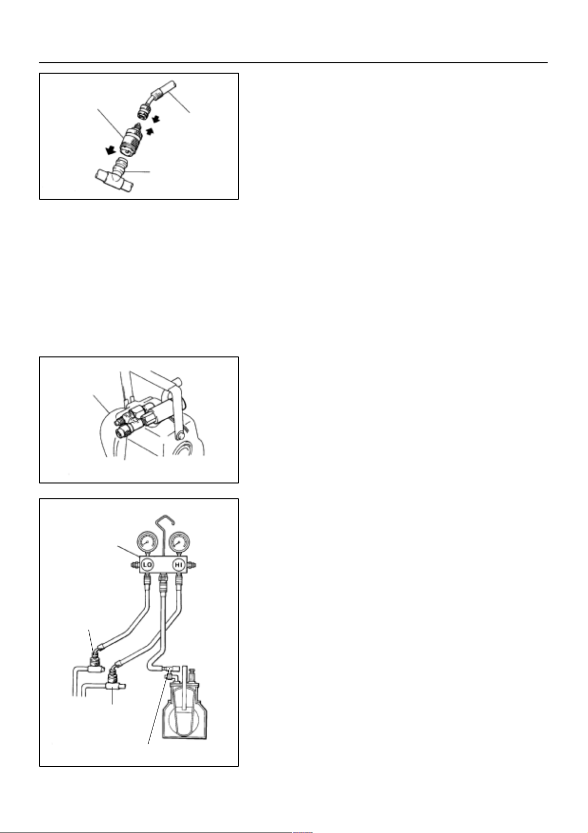
1. ADJUST HOOD IN FORWARD/REARWARD AND
LEFT/RIGHT DIRECTIONS
Adjust the hood by loosening the hood side hinge bolts.
Torque: 13 N·m (130 kgf·cm, 9.4 ft·lbf)
N16539
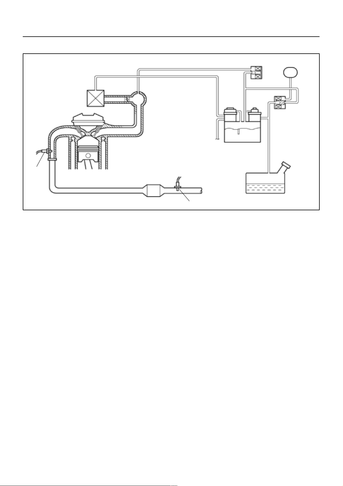
2. ADJUST FRONT EDGE OF HOOD IN VERTICAL
DIRECTIONS
Adjust the hood by turning the cushions.
N16540
N16541
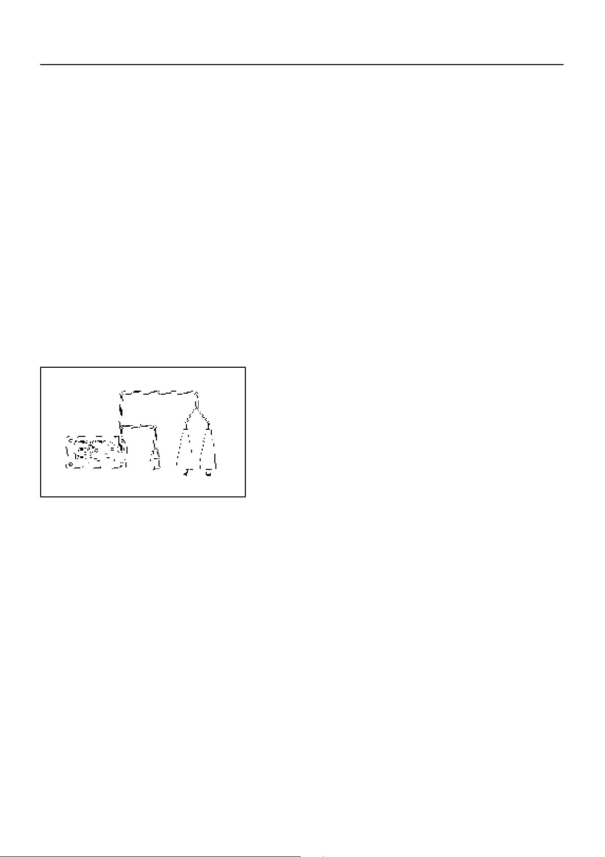
3. ADJUST HOOD LOCK
Adjust the lock by loosening bolts.
Torque: 8.3 N·m (85 kgf·cm, 74 in.·lbf)
1997 PASEO (RM499U)
AC–10
Quick Disconnect
Adapter
Charging
Hose
Service Valve
N13795
–AIR CONDITIONING AIR CONDITIONING SYSTEM
AC1E0–01
EVACUATING
1. CONNECT QUI C K DIS C O N N E CT ADAP T E R TO
CHARGING HOSES
2. REMOVE CAPS FROM SERVICE VALVES ON REFRIGERANT LINES
3. SET ON MANIFOLD GAUGE SET
(a) Close both hand valves of manifold gauge set.
(b) Connect the quick disconnect adapters to the service
valves.
Vacuum Pump
Vacuum Pump Adapter
Manifold
Gauge
Set
Low Pressure
Service Valve
4. EVACUATE AIR FROM REFRIGERATION SYSTEM
(a) Connect the vacuum pump adapter to the vacuum pump.
N13794
(b) Connect the center hose of the manifold gauge set to the
vacuum pump adapter.
(c) Open both the high and low hand valves and run the vacu-
um pump.
(d) After 10 minutes or more, check that the low pressure
gauge indicates 750 mmHg (30 in. Hg) or more.
HINT:
If the reading is 750 mmHg (30 in. Hg) or more, close both hand
valves of manifold gauge set and stop the vacuum pump.
Check the system for leaks and repair if necessary.
(e) Close both the high and low hand valves and stop the vac-
uum pump.
(f) Leave the system in this condition for 5 minutes or more
and check that there is no gauge indicator.
High Pressure
Service Valve
Vacuum Pump Adapter
1997 PASEO (RM499U)
N13791

PP–64
–PREPARATION SUPPLEMENTAL RESTRAINT SYSTEM
EQUIPMENT
To r qu e w r en c h
Bolt: Length: 35 mm (1.38 in.) Pitch: 1.0 mm (0.039 in.)
Diam.: 6.0 mm (0.236 in.)
Tire Width: 185 mm (7.28 in.) Inner diam.: 360mm (14.17 in.) Airbag disposal
Tire with disc wheel Width: 185 mm (7.28 in.)
Inner diam.: 360 mm (14.17 in.)
Vinyl bag Airbag disposal
Airbag disposal
Airbag disposal
PP0MS–01
1997 PASEO (RM499U)

PP–6
–PREPARATION ENGINE MECHANICAL
EQUIPMENT
Caliper gauge
CO/HC meter
Compression gauge
Connecting rod aligner
Cylinder gauge
Dial indicator
Dye penetrant
Engine tune–up tester
Heater
Magnetic finger
Micromerer
OBDII scan tool Idle speed
Piston ring compressor
Piston ring expander
Plastigage
precision straight edge
Soft brush
Spring tester Valve spr ing
Steel square Valve sp rin g
To r qu e w r en c h
Valve sea t cut ter
Vernier c ali per s
PP1A7–01
1997 PASEO (RM499U)

PP–48
EQUIPMENT
Dial indicator
To r qu e w r en c h
Drill
Spring tension gauge
–PREPARATION SUSPENSION AND AXLE
PP16I–01
1997 PASEO (RM499U)

PP–32
EQUIPMENT
Calipers
Dial indicator
To r qu e w r en c h
–PREPARATION CLUTCH
PP155–01
1997 PASEO (RM499U)

–PREPARATION BODY
EQUIPMENT
Clip remover
To r qu e w r en c h
To r x d r i v e r
Hog ring pliers
Hand riveter
Tape To av o i d su r f a ce d a m ag e
Adhesive tape To av o i d su r f a ce d a m ag e
Double–stick tape
Adhesive
Cleaner
Shop rag
Knife
Sealer gun
Brush
Putty spatula
Glass plate or similar object
Wooden block or similar object
Piano wire
Rope (no projections, difficult to break) Seat belt pretensioner
Tire Width: 185 mm (7.28 in.) Inner diam: 360 mm (14.17 in.) Seat belt pretensioner
Tire with disk wheel Width: 185 mm (7.28 in.)
Inner diam: 360 mm (14.17 in.)
Vinyl bag Seat belt pretensioner
Seat belt pretensioner
PP–71
PP0AZ–05
1997 PASEO (RM499U)

PP–14
EQUIPMENT
Heater
Radiator cap tester
Thermometer
To r qu e w r en c h
Vernir ca liper s
–PREPARATION COOLING
PP1AB–01
1997 PASEO (RM499U)

–PREPARATION STEERING
EQUIPMENT
Belt tension gauge Drive belt
Caliper gauge PS vane pump
Calipers PS vane pump
Cylinder gauge PS gear
Dial indicator PS gear
Feeler gauge PS vane pump
Micrometer PS vane pump
To r qu e w r en c h
PP–59
PP18L–01
1997 PASEO (RM499U)

–PREPARATION MAINTENANCE
MAINTENANCE
EQUIPMENT
Mirror Brake hose
To r qu e w r en c h
PP–1
PP1A9–01
1997 PASEO (RM499U)

–PREPARATION CHARGING
EQUIPMENT
Battery specific gravity gauge
Belt tension gauge
To r qu e w r en c h
Vernier c ali per s Rotor (Slip ring), Brush
PP–29
PP19Q–01
1997 PASEO (RM499U)

EQUIPMENT
Dial indicator with magnetic base
Feeler gauge
Micrometer
To r qu e w r en c h
Magnetic finger
PP–37
–PREPARATION MANUAL TRANSAXLE
PP150–01
1997 PASEO (RM499U)

–PREPARATION AIR CONDITIONING
EQUIPMENT
Voltmeter
Ammeter
Ohmmeter
Te s te r l e ad
Thermometer Thermister
To r qu e Wrench
Dial indicator Magnetic clutch
PP–77
PP17H–01
1997 PASEO (RM499U)

EQUIPMENT
Spark plug cleaner
PP–23
–PREPARATION IGNITION
PP19V–01
1997 PASEO (RM499U)

PP–52
–PREPARATION BRAKE
EQUIPMENT
To r qu e w r en c h
Micrometer Brake disk
Dial indicator Brake disk
Vernier c ali per s Brake drum
PP0JN–01
1997 PASEO (RM499U)

–PREPARATION BODY ELECTRICAL
EQUIPMENT
Voltmeter
Ammeter
Ohmmeter
Te s t l e a d
Bulb (3.4W) Fuel sender gauge, Seat belt warning relay
Bulb (21W) Turn signal flasher relay
Dry cell battery Fuel sender gauge
To r qu e w r en c h
Masking tape Rear window defogger wire
Tin foil Rear window defogger wire
PP–67
PP0IG–02
1997 PASEO (RM499U)

PP–42
–PREPARATION AUTOMATIC TRANSAXLE
EQUIPMENT
OBD II scan tool
Straight edge Check torque converter clutch installation
Dial indicator or dial indicator with magnetic base Measure inside diameter or piston stroke
To r qu e w r en c h
PP17L–01
1997 PASEO (RM499U)

–PREPARATION SFI
EQUIPMENT
Carburetor cleaner
OBDII scan tool
Soft brush Throttle body
Sound scope Injector
Thermometer
To r qu e w r en c h
Vacuu m ga uge
PP–11
PP1A3–01
1997 PASEO (RM499U)

PP–26
–PREPARATION STARTING
EQUIPMENT
Caliper gauge Center bearing for planetary type
Dial indicator Commutator
Magnetic finger
Micrometer Planet carrier shaft for
planetary type
Press Reduction type
Pull scale Brush spring
Sandpaper Commutator
To r qu e w r en c h
V–block
Vernier c ali per s Commutator
Brush
PP19T–01
1997 PASEO (RM499U)

–PREPARATION LUBRICATION
EQUIPMENT
Oil pressure gauge
Straight edge Oil pump
To r qu e w r en c h
PP–19
PP19Y–01
1997 PASEO (RM499U)

PP–8
EMISSION CONTROL
EQUIPMENT
To r q ue w re n c h
Vacuu m ga uge
–PREPARATION EMISSION CONTROL
PP1A4–01
1997 PASEO (RM499U)

DI–215
–DIAGNOSTICS SUPPLEMENTAL RESTRAINT SYSTEM
DI4PM–01
DIAGNOSTIC TROUBLE CODE CHART
If a malfunction code is displayed during the DTC check, check the circuit listed for that code in the table
below (Proceed to the page given for that circuit.).
DTC No.
(See Page)
Normal
(DI–252)
11
(DI–220)
12
(DI–227)
13
(DI–234)
14
(DI–239)
31
(DI–243)
53
(DI–245)
54
(DI–249)
Detection Item Trouble Area
! System normal –
! Source voltage drop ! Battery
! Airbag sensor assembly
! Short in squib circuit (to ground) ! Steering wheel pad (D squib)
! Front passenger airbag assembly (P squib)
! Spiral cable
! Airbag sensor assembly
! Wire harness
! Short in squib circuit (to B+) ! Steering wheel pad (D squib)
! Front passenger airbag assembly (P squib)
! Spiral cable
! Airbag sensor assembly
! Wire harness
! Short in D squib circuit ! Steering wheel pad (D squib)
! Spiral cable
! Airbag sensor assembly
! Wire harness
! Open in D squib circuit ! Steering wheel pad (D squib)
! Spiral cable
! Airbag sensor assembly
! Wire harness
! Airbag sensor assembly malfunction !Airbag sensor assembly
! Short in P squib circuit ! Front passenger airbag assembly (P squib)
! Airbag sensor assembly
! Wire harness
! Open in P squib circuit ! Front passenger airbag assembly (P squib)
! Airbag sensor assembly
! Wire harness
SRS
Warning Light
OFF
ON
ON
ON
ON
ON
ON
ON
ON
HINT:
! When the SRS warning light remains lit up and the DTC is the normal code, this means a source voltage
drops.
This malfunction is not stored in memory by the airbag sensor assembly and if the power source voltage returns to normal, the SRS warning light will automatically go out.
! When 2 or more codes are indicated, the codes will be displayed in numeral order starting from the
lowest numbered code.
! If a code not listed on the chart is displayed, the airbag sensor assembly is faulty.
1997 PASEO (RM499U)

DI–304
–DIAGNOSTICS CRUISE CONTROL SYSTEM
DI4QM–01
DIAGNOSTIC TROUBLE CODE CHART
If a malfunction code is displayed during the diagnostic code check, check the circuit listed for that code in
the table below (Proceed to the page given for that circuit).
DTC No.
(See Page)
11, 15
(DI–310)
12
(DI–312)
14
(DI–314)
21
(DI–316)
23
(DI–318)
32
(DI–319)
41 ! Cruise control ECU ! Cruise control ECU
42 ! Source voltage drop ! Power source
51
(DI–322)
! Short in actuator motor circuit
! Open in actuator motor circuit
! Short in magnetic clutch circuit
! Open (0.8 sec.) in magnetic clutch circuit
! Actuator mechanical malfunction
! Speed signal is not input to the cruise control ECU while
cruise control is set
! Actual vehicle Speed has dropped either by 16 km/h (10 mph)
or more below the set speed, or by 20 % or more of the set
speed
! Ve hic le spe ed sen sor pu lse is abnormal. (When speed sig nal
is not input to the ECU below 0.2 sec., code will be dis-
played.)
! Short in control switch circuit
! Short in idle signal circuit
Detection Item Trouble Area
! Cruise control actuator
! Harness or connector between actuator and cruise control
ECU
! Cruise control ECU
! Cruise control actuator magnetic clutch
! Harness or connector between ECU and magnetic clutch,
magnetic clutch and body ground
! Cruise control ECU
! Cruise control actuator
! Harness or connector between actuator and cruise control
ECU
! Cruise control ECU
! Ve hicle sp eed se nso r
! Combination meter
! Harness or connector between vehicle speed sensor and
combination meter, combination meter
! Cruise control ECU
! Ve hicle sp eed se nso r
! Harness or connector in SPD circuit
! Cruise control ECU
! Cruise control switch
! Harness or connector between control switch and cruise
control ECU
! Cruise control ECU
! Throttle position sensor
! Harness or connector between cruise control ECU and
throttle position sensor
! Cruise control ECU
1997 PASEO (RM499U)

DI–137
–DIAGNOSTICS AUTOMATIC TRANSAXLE
DI4ON–02
DIAGNOSTIC TROUBLE CODE CHART
If a DTC is displayed during the DTC check, check the circuit listed for that code in the table below and proceed to the page given.
DTC No.
(See Page)
P0500
(DI–144)
P0750
(DI–145)
P0753
(DI–146)
P0755
(DI–145)
P0758
(DI–146)
P0770
(DI–150)
P0773
(DI–152)
P1520
(DI–155)
P1700
(DI–156)
P1780
(DI–160)
Vehic le Sp eed Sensor Malfunc-
tion
(No.1 Vehicle Speed Sensor)
Shift Solenoid A Malfunction
(Shift Solenoid Valve No.1)
Shift Solenoid A Electrical Mal-
function
(Shift Solenoid Valve No.1)
Shift Solenoid B Malfunction
(Shift Solenoid Valve No.2)
Shift Solenoid B Electrical Mal-
function
(Shift Solenoid Valve No.2)
Shift Solenoid E Malfunction
(Shift Solenoid Valve SL)
Shift Solenoid E Electrical Mal-
function
(Shift Solenoid Valve SL)
Stop Light Switch Signal Mal-
function
Speed Sensor No.2 Circuit Mal-
function
(No.2 Vehicle Speed Sensor)
Park/Neutral Position Switch
Malfunction
* : "...MIL light up
Detection Item Trouble Area MIL * Memory
! Open or short in No.1 vehicle speed sensor circuit
! No.1 vehicle speed sensor
! Combination meter
! ECM
! Shift solenoid valve No.1 is stuck open or closed
! Va lve b ody i s blo cked up or stu ck
! Open or short in shift solenoid valve No.1 circuit
! Shift solenoid valve No.1
! ECM
! Shift solenoid valve No.2 is stuck open or closed
! Va lve b ody i s blo cked up or stu ck
! Open or short in shift solenoid valve No.2 circuit
! Shift solenoid valve No.2
! ECM
! Shift solenoid valve SL is stuck open or closed
! Va lve b ody i s blo cked up or stu ck
! Lock–up clutch
! Open or short in shift solenoid valve SL circuit
! Shift solenoid valve SL
! ECM
! Open or short in shift solenoid valve SL circuit.
! Stop light switch
! ECM
! Open or short in No.2 vehicle speed sensor circuit
! No.2 vehicle speed sensor
! ECM
! Short in park/neutral position switch circuit
! Park/neutral position switch
! ECM
" #
" #
" #
" #
" #
" #
" #
" #
" #
" #
1997 PASEO (RM499U)

DI–177
–DIAGNOSTICS ANTI–LOCK BRAKE SYSTEM
DI4P4–01
DIAGNOSTIC TROUBLE CODE CHART
HINT:
! Using SST 09843–18020, connect the terminals Tc and E1, and remove the short pin.
! If any abnormality is not found when inspection parts, inspect the ECU.
If a malfunction code is displayed during the DTC check, check the circuit listed for that the code. For details
of each code, turn to the page referred to under the ”See page” for the respective ”DTC No.” in the DTC chart.
DTC No.
(See Page)
11
(DI–179)
12
(DI–179)
13
(DI–182)
14
(DI–182)
21
(DI–185)
22
(DI–185)
23
(DI–185)
24
(DI–185)
31
(DI–188)
32
(DI–188)
33
(DI–188)
34
(DI–188)
41
(DI–194)
51
(DI–197)
Always ON Malfunction in ECU ! ECU
Open circuit in ABS control (solenoid) relay circuit
Short circuit in ABS control (solenoid) relay circuit
Open circuit in ABS control (motor) relay circuit
Short circuit in ABS control (motor) relay circuit
Open or short circuit in solenoid circuit for right front wheel
Open or short circuit in solenoid circuit for left front wheel
Open or short circuit in solenoid circuit for right rear wheel
Open or short circuit in solenoid circuit for left rear wheel
Right front wheel speed sensor signal malfunction
Left front wheel speed sensor signal malfunction
Right rear wheel speed sensor signal malfunction
Left rear wheel speed sensor signal malfunction
Low battery positive voltage or abnormally high battery
positive voltage
Pump motor is locked
Open in pump motor ground
Detection Item Trouble Area
! ABS control (solenoid) relay
! Open or short in ABS control (solenoid) relay circuit
! ABS control (solenoid) relay
! B+ short in ABS control (solenoid) relay circuit
! ABS control (motor) relay
! Open or short in ABS control (motor) relay circuit
! ABS control (motor) relay
! B+ short in ABS control (motor) relay circuit
! ABS actuator
! Open or short in SFR circuit
! ABS actuator
! Open or short in SFL circuit
! ABS actuator
! Open or short in SRR circuit
! ABS actuator
! Open or short in SRL circuit
! Right front, left front, right rear and left rear speed sensor
! Open or short in each speed sensor circuit
! Senser rotor
! Battery
! IC regulator
! Open or short in power source circuit
! ABS pump motor
1997 PASEO (RM499U)

DI–14
–DIAGNOSTICS ENGINE
DI4NK–01
DIAGNOSTIC TROUBLE CODE CHART
HINT:
Parameters listed in the chart may not be exactly the same as your reading due to the type of instrument
or other factors.
If a malfunction code is displayed during the DTC check in check mode, check the circuit for that code listed
in the table below, for details of each code, turn to the page referred to under the ’’See page ’’ for the respective ’’DTC No.’’ in the DTC chart.
SAE Controlled:
DTC No.
(See Page)
P0105
(DI–21)
P0106
(DI–25)
P0110
(DI–27)
P0115
(DI–31)
P0116
(DI–35)
P0120
(DI–36)
P0121
(DI–40)
P0125
(DI–41)
P0130
(DI–44)
P0133
(DI–47)
P0136
(DI–48)
P0141
(DI–50)
P0171
(DI–51)
Manifold Absolute
Pressure/Barometric
Pressure Circuit
Malfunction
Manifold Absolute Pressure
Barometric Pressure Circuit
Range/Performance
Problem
Intake Air Temp. Circuit
Malfunction
Engine Coolant Temp. Circuit
Malfunction
Engine Coolant Temp. Circuit
Range/Performance Problem
Throttle/Pedal Position
Sensor/Switch ”A” Circuit
Malfunction
Throttle/Pedal Position
Sensor/Switch ”A” Circuit
Range/Performance Problem
Insufficient Coolant Temp. for
Closed Loop Fuel Control
(Except California Spec.)
Oxygen Sensor Circuit Malfunc-
tion (Bank 1 Sensor 1)
Oxygen Sensor Circuit
Slow Response
(Bank 1 Sensor 1)
Heated Oxygen Sensor Circuit
Malfunction
(Bank 1 Sensor 2)
Heated Oxygen Sensor Heater
Circuit Malfunction
(Bank 1 Sensor 2)
System too Lean
(Fuel Trim)
Detection Item Trouble Area MIL*1 Memory
*: " !!! MIL lights up
! Open or short in manifold absolute pressure sensor circuit
! Manifold absolute pressure sensor
! ECM
! Manifold absolute pressure sensor " "
! Open or short in intake air temp. sensor circuit
! Intake air temp. sensor
! ECM
! Open or short in engine coolant temp. sensor circuit
! Engine coolant temp. sensor
! ECM
! Engine coolant temp. sensor
! Cooling system
! Open or short in throttle position sensor circuit
! Throttle position sensor
! ECM
! Throttle position sensor " "
! Open or short in heated oxygen sensor circuit
! Oxygen sensor
! Heated oxygen sensor
! Fuel trim malfunction
! Oxygen sensor " "
! Heated oxygen sensor " "
! Open or short in heater circuit of heated oxgen sensor
! Heated oxgen sensor heater
! ECM
! Air intake (hose loose)
! Fuel line pressure
! Injector blockage
! Manifold absolute pressure sensor
! Engine coolant temp. sensor
" "
" "
" "
" "
" "
" "
" "
" "
"* "
1997 PASEO (RM499U)

–DIAGNOSTICS ENGINE
DI–15
DTC No.
(See Page)
P0172
(DI–51)
P0300
(DI–54)
P0301
P0302
P0303
P0304
(DI–54)
P0325
(DI–59)
P0335
(DI–62)
P0340
(DI–65)
P0420
(DI–67)
P0440
(DI–70)
P0441
(DI–76)
P0446
(DI–76)
P0450
(DI–87)
System too Rich
(Fuel Trim)
Random/Multiple Cylinder
Misfire Detected
Misfire Detected
– Cylinder 1
– Cylinder 2
– Cylinder 3
– Cylinder 4
Knock Sensor 1 Circuit
Malfunction
Crankshaft Position Sensor
”A” Circuit Malfunction
Camshaft Position Sensor
Circuit Malfunction
Catalyst System Efficiency
Below Threshold
Evaporative Emission Control
System Malfunction
Evaporative Emission Control
System Incorrect Purge Flow
Evaporative Emission Control
System Vent Control
Malfunction
Evaporative Emission Control
System Pressure Sensor
Malfunction
*: MIL lights up
Detection Item Trouble Area MIL*1 Memory
! Fuel line pressure
! Injector leak, blockage
! Manifold absolute pressure sensor
! Engine coolant temp. sensor
! Ignition system
! Injector
! Fuel line pressure
! Compression pressure
! Va lve cle ara nce no t to spe cif ica tion
! Va lve timi ng
! Manifold absolute pressure sensor
! Engine coolant temp. sensor
! Open or short in knock sensor 1 circuit
! Knock sensor 1 (looseness)
! ECM
! Open or short in crankshaft position sensor circuit
! Crankshaft position sensor
! Starter
! ECM
! Open or short in camshaft position sensor circuit
! Camshaft position sensor
! Starter
! ECM
! Three–way catalytic converter
! Open or short in heated oxygen sensor (bank 1 sensor 2)
circuit
! Heated oxygen sensor (bank 1 sensor 2)
! Open or short in heated oxygen sensor (bank 1 sensor 1) /
A/F sensor *2 circuit
! Heated oxygen sensor (bank 1 sensor 1) / A/F sensor *2
! Va por p ressu re se nsor
! Fuel tank cap incorrectly installed
! Fuel tank cap cracked or damaged
! Va cuu m h ose cr ack ed, ho led , blocked, damaged or
disconnected
! Hose or tube cracked, holed, damaged or loose
! Fuel tank cracked, holed or damaged
! Charcoal canister cracked, holed or damaged
! Open or short in VSV circuit for EVAP
! VSV for EVAP
! Open or short in vapor pressure sensor circuit
! Va por p ressu re se nsor
! Open or short in VSV circuit for vapor pressure sensor
! VSV for vapor pressure sensor
! Va cuu m h ose da mag ed, bl ock ed or disconnected
! Charcoal canister
! Open or short in vapor pressure sensor circuit
! Va por p ressu re se nsor
! ECM
"* "
" "
"* "
"* "
"* "
" "
" "
" "
" "
" "
1997 PASEO (RM499U)

DI–16
–DIAGNOSTICS ENGINE
DTC No.
(See Page)
P0500
(DI–89)
P0505
(DI–92)
Vehicle Spe ed Se nsor
Malfunction
Idle Control System
Malfunction
Detection Item Trouble Area MIL*1 Memory
*: " !!! MIL lights up
Manufacturer Controlled:
DTC No.
(See Page)
P1300
(DI–95)
P1335
(DI–100)
P1520
(DI–101)
P1600
(DI–104)
P1780
(DI–106)
Igniter Circuit Malfunction
Crankshft Position Sensor Cir-
cuit Malfunction
(during engine running)
Stop Light Switch Signal Mal-
function
ECM BATT Malfunction
Park/Neutral Position Switch
Malfunction
Detection Item Trouble Area MIL* Memory
*: " !!! MIL lights up
!!! MIL does not light up
*: !
! Open or short in speed sensor circuit
! Ve hicle sp eed se nso r
! Speedometer cable
! ECM
! IAC valve is stuck or closed
! Open or short in IAC valve circuit
! Open or short in AC1 signal circuit
! Air intake (hose loose)
! Open or short in IGF or IGT1 circuit from igniter
! Igniter
! ECM
! Open or short in crankshaft position sensor circuit
! Crankshaft position sensor
! ECM
! Short in stop light switch signal circuit
! Stop light switch
! ECM
! Open in back up power source circuit
! ECM
! Short in park/neutral position switch circuit
! Park/neutral position switch
! ECM
" "
" "
" "
! "
" "
" "
" "
1997 PASEO (RM499U)
DRAWING
Air Cleaner
Oxygen
Sensor
(Bank 1
Sensor 1)
TWC
–EMISSION CONTROL PARTS LAYOUT AND SCHEMATIC DRAWING
Vapor Pressure Sensor
VSV for EVAP
Charcoal Canister
Heated Oxygen Sensor
(Bank 1 Sensor 2)
EC–3
EC07F–01
VSV for Vapor
Pressure Sensor
S05884
1997 PASEO (RM499U)
RS–11
–SUPPLEMENTAL RESTRAINT SYSTEM STEERING WHEEL PAD AND SPIRAL CABLE
RS030–11
DISPOSAL
HINT:
When scrapping vehicle equipped with an SRS or disposing of
a steering wheel pad (with airbag), always first deploy the airbag in accordance with the procedure described below. If any
abnormality occurs with the airbag deployment, contact the
SERVICE DEPT. of TOYOTA MOTOR SALES, U.S.A., INC.
When disposing of a steering wheel pad with an airbag
deployed in a collision, follow the same procedure given in step
1–(d) in ”DISPOSAL”.
SST
AB0152
CAUTION:
! Never dispose of a steering wheel pad which has an
undeployed airbag.
! The airbag produces a sizeable exploding sound
when it deploys, so perform the operation out–of–
doors and where it will not create a nuisance to
nearby residents.
! When deploying the airbag, always use the specified
SST (SRS Airbag Deployment Tool). Perform the operation in a place away from electrical noise.
SST 09082–00700
! When deploying an airbag, perform the operation at
least 10 m (33 ft) away from the steering wheel pad.
! The steering wheel pad is very hot when the airbag is
deployed, so leave it alone for at least 30 minutes after deployment.
! Use gloves and safety glasses when handling a steer-
ing wheel pad with deployed airbag.
! Always wash your hands with water after completing
the operation.
! Do not apply water, etc. to a steering wheel pad with
deployed airbag.
1997 PASEO (RM499U)
 Loading...