


SERVICE MANUAL
Embroidery Machine
ESP9000
(15 needles)


How to Use this Service Manu
al
1.This service manual applies to the ESP9000.
Model names are indicated only for sections equipped with each model.
2.Refer to the section on TROUBLESHOOTING first.
Trouble often results from two or more causes. The TROUBLESHOOTING
section indicates the correct order and method of troubleshooting. When
need arises to repair the embroidery machine in reference to this Service
Manual, refer to TROUBLESHOOTING first. Then, refer to ADJUSTMENT or
REPLACEMENT as suggested.
3.Only the critical instructions are given.
When a component must be removed for troubleshooting, adjustment or
replacement, the Service manual explains how to remove other components
before the component in question can be removed.
However, the manual does not explain how the other components are fitted,
unless such information is necessary for technical reasons, when adjustment
or replacement is completed.

Inspection & Repairs
1.When parts need to be replaced, use only parts certified by Aishin Seiki Co.,
Ltd., to ensure machine performance.
2.To prevent any accident from occurring, be sure to turn the power OFF
before repair.
CONTENTS
1.
SPECIFICATIONS
...............................................................................................................
.....................1
2.
TROUBLESHOOTING
............................................................................................
.......................
2

2-1 The power supply does not turn
on........................................................................................2
2-2 An error message is displayed ”Check ! SEWING
MOTOR”........................................3
2-3 An error message is displayed “Check ! X
MOTOR”......................................................4
2-4 An error message is displayed ” Check ! Y
MOTOR”.....................................................5
2-5 An error message is displayed ”NEEDLE CASE
ERROR” ............................................6
2-6 Holder does not return to stroke center after home position
return......................7
2-7 Thread comes off
needle.............................................................................................................8
2-8 Skips
stitches..................................................................................................................................
..9
2-9 Needle thread
breaks...................................................................................................................10

2-10 Bobbin thread
breaks...................................................................................................................12
2-11 Needle
breaks..................................................................................................................................1
3
2-12 Thread wiper hook does not
operate....................................................................................14
2-13 Thread trimming
fails....................................................................................................................15
2-14
Puckering...............................................................................................................................
............16
2-15 Improper
tension............................................................................................................................17
2-16 Jump function does not
work...................................................................................................18
2-17 An error message is displayed “THREAD
BREAK” .......................................................19
2-18 Stitch registration slips
out.......................................................................................................20

3.ADJUSTMENT OF MAIN COMPONEN
TS
..................................21
3-1 Timing of the needle and the rotary
hook...........................................................................21
3-2 Position of the hook
support....................................................................................................23
3-3 Standby position of thread
catcher.......................................................................................24
3-4 Blade
pressure................................................................................................................................
25
3-5 Picker
position................................................................................................................................2
7
3-6 Position of the thread wiper
hook..........................................................................................28
3-7 Adjustment of the jump motor
position...............................................................................29
3-8 Tension of drive belts A &

C....................................................................................................30
3-9 Tension of deceleration belts B, D,
E...................................................................................31
3-10 Limit
sensor....................................................................................................................................
..32
3-11 Thread
sensor.................................................................................................................................3
4
3-12 Power
box.........................................................................................................................................
35
4.REPLACEMENT OF MAIN COMPON
ENTS
..........................36
4-1 Rotary
hook.......................................................................................................................................
36
4-2 Thread

cutter...................................................................................................................................3
7
4-3 Thread
catcher................................................................................................................................3
8
4-4 Needle
bar.........................................................................................................................................
.39
4-5 Needle bar
reciprocator...............................................................................................................41
4-6 Thread change
motor...................................................................................................................43
4-7 Power supply
board.......................................................................................................................44
4-8 Power circuit
board........................................................................................................................45
4-9 Jump
motor.....................................................................................................................................
..46
4-10 Main circuit

board...........................................................................................................................47
4-11 Operation box
assembly...............................................................................................................48
4-12 Upper shaft
sensor.........................................................................................................................49
4-13 Sewing machine
motor..................................................................................................................50
4-14 X
motor.....................................................................................................................................
...........51
4-15 Y
motor.....................................................................................................................................
...........52
4-16 Thread wiper
motor........................................................................................................................53
4-17 Thread
sensor...................................................................................................................................
54
4-18 Operation control circuit
board................................................................................................55

4. REPLACEMTNT OF MAIN COMPONENTS
4-9. Jump motor
[Removal]
(1) Remove the needle case.
[Please refer to 『“ 4-5. Needle bar
reciprocator” 』 on page 41]
(2) Remove five set screws (a) and the arm
front cover L. (Fig.1)
(3) Remove each setting screws and the
thread stand plate, bobbin winder base
and rear cover. (Fig.2)
(4) Cut the cable tie and remove the relay
harness.
(5) Remove two setting screws (b) and the
jump motor set. (Fig.3)
(6) Loosen the setting screws (c) and
remove the jump lever holder. (Fig.4)
(7) Remove four setting screws (d) and the
jump motor. (Fig.4)
[Installation]
(1) Install the jump motor with four setting
screws (d). (Fig.4)
(2) Hang the jump lever return spring on
the jump lever holder and pull down the
spring as low as possible so that the
spring will not be located on the jump
positioning collar. (Fig.4)
(3) Tighten the setting screw (c) and check
that the jump lever holder returns with
the spring and stops with the stopper.
(Fig.4)
(4) Install the jump motor set with two
setting screws (b). Adjust the clearance
between the jump lever and the needle
reciprocator at 0.5 mm by moving the
jump motor right and left.
(5) Connect the relay harness, bundle the
cord with cable tie and install the thread
stand plate, bobbin winder base and
rear cover.
(6) Install the needle case.
FIG.1
FIG.2
FIG.3
(a)
Thread stand plate
R
ear cover
Bobbin winder base
(b)
Jump motor set
Jump lever return spring
Jump positioning
collar
Stopper
(d)
(d)
(c)
Jump lever holder
-46-

FIG.4
4-10. Main circuit board
[Removal]
(1) Remove two setting screws (a) and the
table set. (Fig.1)
(2) Remove four set screws (b) and the
base cover rear R. (Fig. 1)
(3) Loosen two setting screws (c), remove
other two set screws (d), move the
case cover upper upwards, disconnect
the connector CN2 and remove the
case cover upper. (Fig.2)
(4) Disconnect all the connectors. (Fig.3)
(5) Remove two setting screws (e) and
remove the main circuit board by
holding the plastic spacer with pliers.
[Installation]
Attached in the reverse procedure of
removal
FIG.1
FIG.2
4.REPLACEMENT OF MAIN COMPONENTS
(b)
Base cover
rear R
Table set
(a)
(d)
(c)
Case cove
r
upper
Main circuit board
(e)
CN2
-47-

FIG.3
-48-
4.REPLACEMENT OF MAIN COMPONENTS
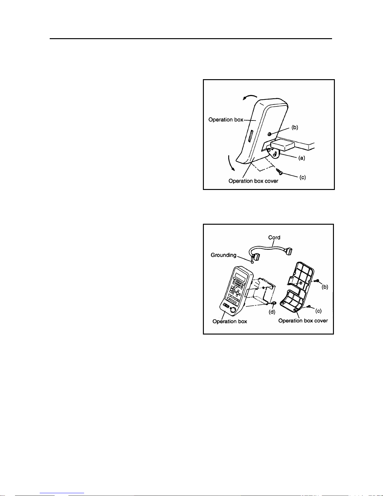
4-11. Operation box assembly
[Removal]
(1) Loosen retaining screw (a) and rotate
the operation box in the direction of the
arrow to set the box in the upright
position (Fig.1).
(2) Remove retaining screw (b) and two
retaining screws (c) and the operation
box cover (Fig.1).
(3) Remove four retaining screws (d).
Unplug the cord and remove the
operation box (Fig.2).
[Installation]
(1) Plug in the cord.
(2) Secure the operation box to the
bracket with four retaining screws (d).
One of these screws is for grounding
(Fig.2).
(3) Mount the operation box cover with
retaining screw (b) and two retaining
screws (c) (Fig.1).
(4) Rotate the operation box to set it at
the desired angle for easy operation
and secure it with retaining screw (a)
(Fig.1).
FIG.1
FIG.2
-49-

4-12. Upper shaft sensor
[Removal]
(1) Remove two setting screws (a) and the
bobbin winder base set. (Fig.1)
(2) Loosen four setting screws (b) and
remove the rear cover. (Fig.1)
(3) Remove two setting screws (c) and the
upper shaft sensor set. Then remove
two setting screws (d) and the upper
shaft sensor. (Figs.1, 2)
(4) Remove four setting screws and the
base cover rear L. (Fig.1)
(5) Loosen two setting screws, remove
other two setting screws, move the
case cover upper upwards, disconnect
the connector CN3 and cut the cable
tie and then remove the upper shaft
sensor. (Refer to Fig.2 on page 47)
[Installation]
(1) Install the upper shaft sensor on the
sensor base with two setting screws (d).
(Fig.3)
(2) Insert the connector of the upper shaft
sensor in CN3 on the main circuit board.
(Fig.5)
(3) Fix the upper shaft sensor set with two
setting screws (c) in the position where
the center of the sensor comes to the
center of the rotation detecting plate.
(Figs.2, 4)
(4) Bundle the cords with cable tie.
(5) Set the DS1-1 on and turn the power
on. Rotate the hand wheel to move the
needle bar to the bottom dead center.
Check that the LCD display shows the
needle position at 180°.
Note: In case the LCD display does not
show 180 ° , loosen the set screw,
adjust the position of the detecting
plate and fix it. (Fig.1)
(6) Install the case cover upper, base
cover rear L, rear cover and bobbin
winder base set.
FIG.1
FIG.2
4.REPLACEMENT OF MAIN COMPONENTS
(c)
Upper shaft sensor set
Upper shaft sensor
(a)
R
ear cover
(b)
(b)
B
ase cover
Rear L
Bobbin winder base set
-50-
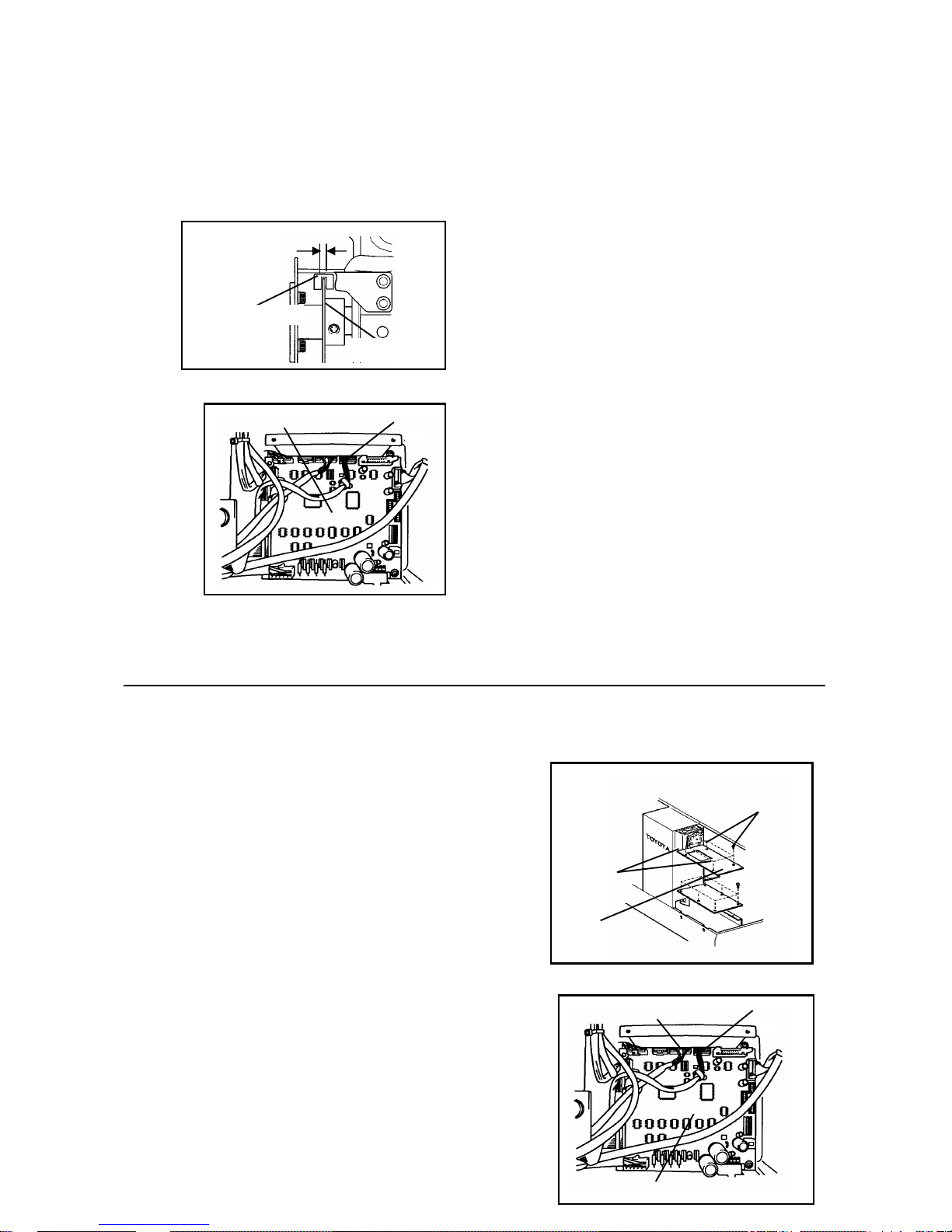
FIG.3
FIG.4
FIG.5
4-13. Sewing machine motor
[Removal]
(1) Remove the rear cover and base cover
rear R.L.
(2) Loosen two set screws (a), remove
other two set screws (b), move the
case cover upper, disconnect CN5 of
the main circuit board and CN3 of the
power circuit board and cut the cable
tie. (Figs.1, 2)
(3) Loosen two setting screws (c), which
are located on the motor side of the
lower shaft joint. (Fig.1)
(4) Remove four setting screws (d) and the
sewing machine motor. (Fig.4)
[Installation]
(1) Two set surfaces of the sewing
machine motor shaft and two setting
screws (c) of the lower shaft joint are
aligned and insert the sewing machine
motor.
(2) Fix the sewing machine motor with four
setting screws (d). (Fig.4)
Center
(3) Insert two setting screws (c) of the
lower shaft joint gradually, locate them
vertically to the setting points and
tighten them.
Upper shaft sensor
Detecting plate
(4) Insert two connectors and bundle the
cords with the cable tie.
(5) Install case cover upper with four
setting screws (a) and (b). (Fig.1)
CN3
Main circuit board
(6) Install the base cover rear R.L. and the
rear cover.
FIG.1
4.REPLACEMENT OF MAIN COMPONENTS
(b)
(a)
Case cove
r
upper
CN3
CN5
-51-
Main circuit board

FIG.2
FIG.3
FIG.4
4-14. X motor
[Removal]
(1) Remove two setting screws (a) and
motor cover. (Fig.1).
(2) Loosen the nut and remove the
setting screw (b). (Fig.2)
(3) Disconnect the connectors. Remove
two setting screws (c) and the X
motor. (Fig.2)
(4) Remove four setting screws (d) and X
motor from the bracket. (Fig.2)
[Installation]
Power circuit board
Lower shat joint
(1) Mount the X motor to the motor base
with four setting screws (d) (Fig.2).
Sewing machine
motor
(c)
(2) Set the X motor gear to the belt and
temporarily secure the motor base to
the X base B with two setting screws
(c) (Fig.2).
Arm bed
(3) Adjust the belt tension by setting
screw (b) and firmly tighten two
setting screws (c), then tighten the
nut. (Figs.2, 3)
Power circuit board
Note: Check the tension, after tighting
screws (c).
(4) Insert the connector.
(d)
Sewing machine
motor
4.REPLACEMENT OF MAIN COMPONENTS
(a)
Motor cover
-52-

FIG.1
FIG.2
X base B
(d)
Nut
(b)
4-15. Y motor
[Removal]
(1) Remove four set screws (a) and the
base cover rear R. (Fig.1)
(2) Remove two setting screws (b) and the
fan set. (Fig.2)
(3) Remove the Y pulley box adjusting
screw (c) and nut (d) and loosen
setting screw (e) and nut (f). (Fig.2)
4.REPLACEMENT OF MAIN COMPONENTS
(c)
X motor
Motor base
-53-

(4) Disconnect the connector, remove two
set screws (g) and Y motor bracket set.
(Fig.3)
(5) Remove four setting screws (h) and the
Y motor. (Fig.4)
[Installation]
(1) Mount the Y motor to its bracket with
four setting screws (h). (Fig.4)
(2) Set the Y motor gear to the belt and
temporarily secure them with two
setting screws (g). (Fig.3)
(3) Adjust the belt tension with setting
screw (e), and then firmly tighten with
two setting screws (g) and nut (f).
(Fig.3)
Note: Check the tension, after tighting
screws (g).
(4) Insert the Y pulley box adjusting
screw (c) into the backmost position
and tighten the nut (d). (Fig.3)
(5) Mount the fan set with two setting
screws (b). (Fig. 2)
(6) Insert the connector.
FIG.1
FIG.2
Base cover
rear R
(a)
Fan set
(b)
Y motor bracket set
(g)
(d)
(f)
(c)
(e)
-54-
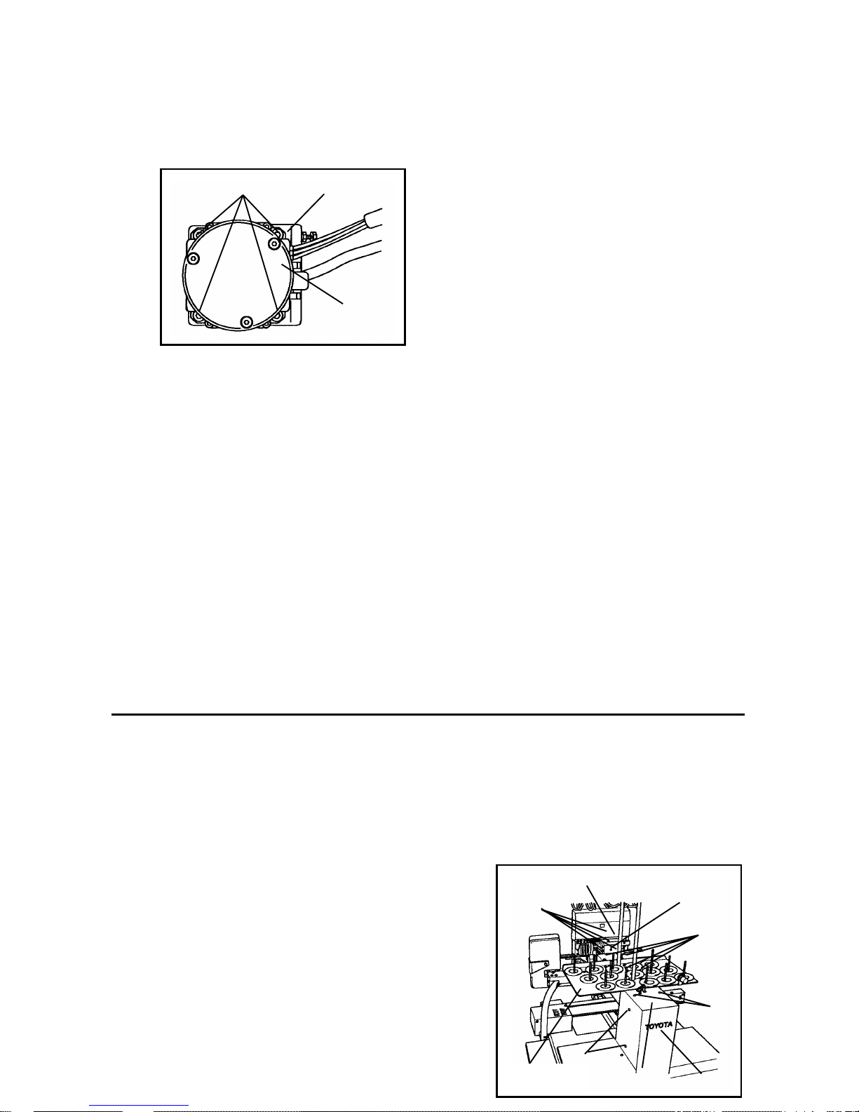
FIG.3
FIG.4
4-16. Thread wiper motor
[Removal]
(1) Remove the each setting screws (a)
and the change cover, the relay circuit
board cover, the thread stand plate,
the bobbin base and the rear cover.
(Fig.1)
(2) Cut a cable tie and remove the relay
connector.
(3) Remove the setting screw (b) and two
setting screws (c), and the thread
wiper motor. (Fig.1)
(4) Remove the setting screw (d) and (e),
and the upper thread hook lever.
(Fig.3)
(5) Remove the three setting screws (f)
and the motor base.(Fig.3)
Note: Be sure to insert the small
washer that is contained in each
setting screws of (3) and (4) sections.
Y motor bracket
(h)
[Installation]
Y moto
r
(1) Attached in the reverse procedure of
removal
Note: Set the vertical position of the
upper thread hook lever slightly
upward, and make sure that the
connecting rod plate has a little play.
(2) After attaching, check the distance A
from the needle center to the thread
wiper hook tip. [Please refer to 『“3-6
Position of the thread wiper hook.” 』
on page 28 ]
(3) If the distance A differs from that
specified, loosen two setting screw (c)
and adjust by moving the thread wiper
motor base up/down.
4.REPLACEMENT OF MAIN COMPONENTS
Change cover
Relay circuit
board cover
(a)
(a)
(a)
(a)
-55-
Thread stand
plate
Bobbin winder
base
Rear cover
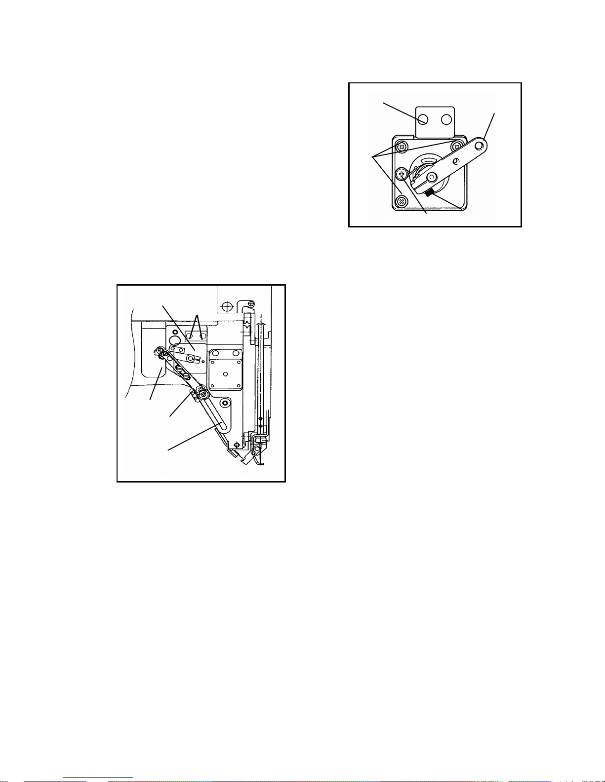
FIG.1
FIG.2
Motor base
Upper thread
hook leve
r
(f)
(d)
(e)
Thread wiper
motor base
(c)
FIG.3
(b)
Thread wipe
r
hook base
Connecting
rod plate
-56-

4.REPLACEMENT OF MAIN COMPONENTS
4-17. Thread sensor
[Removal]
(1) Remove the two each setting screws
(a), then remove the change cover and
relay circuit board cover. (Fig.1)
(2) Remove the connector CN2.
(3) Remove the tension base cover.
(Fig.1)
(4) Raised the connector upwards and
disconnect it.
(5) Cut the cable tie, remove the two
setting screws (b) then remove the
sensor arm. (Fig.4)
(6) Extract the thread sensor base from
the thread sensor rail; remove the
setting screw (c) and the thread
sensor board. (Figs.3, 4)
[Installation]
(1) Attach the sensor board with the
setting screw (c). (Fig. 4)
(2) Put the code of thread sensor base
upwards into the thread sensor rail.
(Fig. 3)
(3) Putting a sensor arm into the slot of
the thread sensor base and secure it
with two setting screws (b). (Fig.2)
Note: At this time, check the sensor
position.
[Please refer to 『 “ 3-11. Thread
sensor” 』 on page 34]
(4) Secure the cord with a cable tie and
insert the connector.
Note: The blue field of a code is
turned and inserted in a spool side. At
this time, check the connector
connection by pulling a code with
hand.
(5) Mount the relay circuit board cover,
change cover and tension base cover.
Tension base cover
(a)
Change
cover
Relay circuit board cove
r
FIG.1
FIG.2
(b)
Sensor arm
Thread sensor rail
Thread sensor base
FIG.3
(c)
Sensor board
FIG.4
-57-

4-18. Operation control circuit board
[Removal]
(1) Remove four setting screws (a) and
the base cover rear R. (Fig.1)
(2) Loosen the two setting screws (b),
remove the two setting screws (c) and
disconnect connectors CN12 and CN7,
then remove the case cover upper.
(Fig.2,3)
(3) Remove the two setting screws (d) and
the resin spacers, then remove the
console board (Fig.4).
[Installation]
Attached in the reverse procedure of
removal.
4.REPLACEMENT OF MAIN COMPONENTS
FIG.1
FIG.2
(a)
Base cover
rear R
(c)
(b)
Case cover
upper
CN12
CN7
FIG.3
(d)
Console board
-58-

FIG.4
-59-

1.SPECIFICATIONS
1.SPECIFICATIONS
ESP9000
No Item Specifications
1 Type of stitch
Lock stitch type sewing machine (for automatic embroidery
only)
2 Rotary hook Vertical 2 revolution type (eccentric)
3 Thread take-up lever Cam take-up lever
4 Needle bar stroke 50 ± 0.2 mm
5 Number of needles 15 (auto changing)
6 Applicable needles Organ DB×K5Z #11
7 Presser foot Needle bar linked driving system (with noise
reduction mechanism)
8 Bobbin thread winding Semi-auto winding (auto return, also stop)
9 Thread trimming method Horizontal reciprocation (motor drive)
10 Thread wiper Motor drive sliding type (with thread retaining
mechanism)
11 Picker method Picking at start, end of sewing and cutting thread
12 Stitch speed 1,200spm maximum (800spm standard)
13 Embroidery area 360 mm long × 500 mm wide
14 Embroidery control and
indication
Touch switch control with LED/LED displays
15 Stitch memory 280,000 stitches
16 Memory back-up Memory saved during operation and after power off;
kept for 4 weeks
17 Weight 80 ± 1kg (without table)
18 Machine oil High grease NX 2, molybdenum grease NO 2, SF oil
(multi-grade)
19 Drive motor AC servo motor (machine revolution)
20 Control motor AC servo motor (X axis, Y axis)
21 Needle thread failure detection Rotary detection system (photo sensor)
-1-

22 Power supply and consumption 100~120/200~240VAC, 50/60Hz, 220W
23 Dimensions 835(H) x 745(W) x 740(D)
-2-

2.TROUBLESHOOTING
2.TROUBLESHOOTING
2-1 The power supply does not
turn on
・ Power cord may be unplugged (AC power
cord).
・ Cable from the power box to the embroidery
machine may be disconnected (DC power
cord).
Main circuit board
-2-

Item Method Standard Action
Fuse
(outside)
250V6.3
A,without
fusion
Replace
fuse.
5V power
supply
Take out fuse and inspect it
visually
Check the voltage across ①
and ⑦with a circuit tester.
5.0to5.2V
when
turned on
Adjust or
replace
the
power
box. See
P.44.
Connection
of
connector
CN 12
Must be
connecte
d
correctly
Connect
the cable
correctly or
replace the
main circuit
board See
.47. P
Connection
of
connector
CN 7
Must be
connecte
d
correctly
Connect
the cable
correctly
or
replace
the main
circuit
board.
See
.55. P
CN12
CN7
Connection
of
connector
CN 3
Remove
the cover
and
inspect
connectio
n
visually
Must be
connecte
d
correctly
Connect
correctly
or
replace
defective
connectors.
See P48.
-3-

2.TROUBLESHOOTING
・ Upper shaft torque may be too large
・ Needle may be interfering with the embroidery
hoop.
・ Thread may be stuck.
Item Method Standard Action
24V power
supply
Check the voltage across⑤
and ⑪ with a circuit tester
hile shorting⑧to⑨. w
24.0 to
24.5V
Replace
See
P.44.
Connector
connection
Must be
connecte
d
correctly
Connect
correctly
Resistance
Check connector visually.
Disconnect the power
connector, and check the
resistance between ①and②,①
and③,②and③ with a circuit
tester.
0.2 to 0.6
Ω
Replace.
See
P.50.
Connection
of
connector
CN 3
Check the connector
visually.
Must be
connecte
d
correctly
Connect
correctly
or
replace
See
P.45.
CN3
Operation panel
“Check! SEWING
MOTOR ”
2-2 An error message is
displayed
-4-

Connection
of
connector
CN 3
Must be
connecte
d
correctly
Connect
the cable
correctly
or replace
the main
the circuit
board.
See P.47.
CN3
-5-