

Toyota Corolla FR AE86L Series 1987 Wiring Diagram

FOREWORD
This wiring diagram has been prepared
on
the
electrical system
AE86L series.
All
information
information
and procedures are subject
at
in
the
the
time
of
the
1987 TOYOTA COROLLA FR
manual
of
is
based
publication. However, specifications
to
change
without
TOYOTA MOTOR CORPORATION
to
provide information
on
the
latest
product
notice.
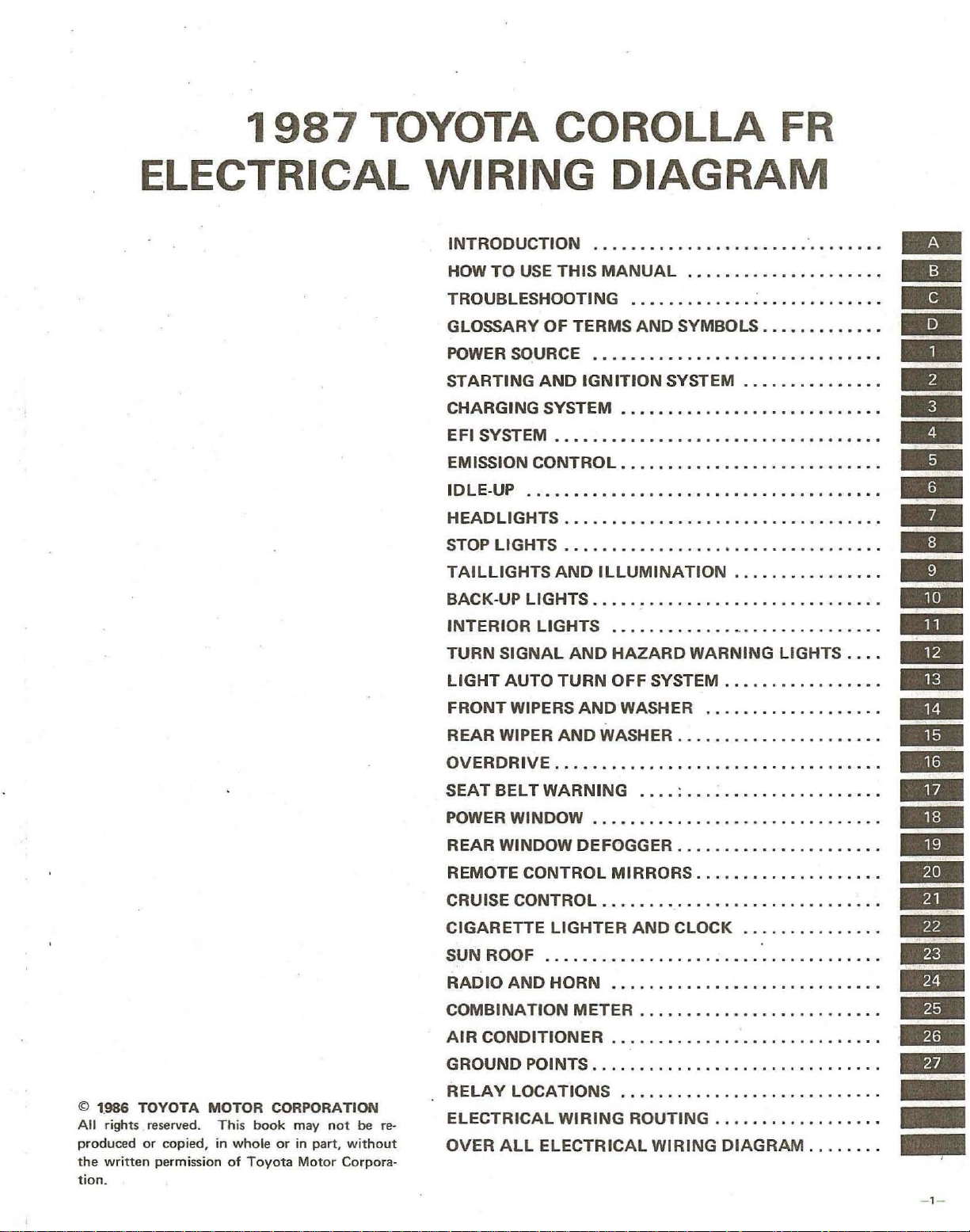
1987
TOYOTA COROLLA
FR
ELECTRICAL
WIRING
INTRODUCTION
HOW
TO
USE
THIS
TROUBLESHOOTING
GLOSSARY
POWER
STARTING
CHARGING SYSTEM
EFI SYSTEM
EMISSION CONTROL
IDLE·UP
HEADLIGHTS .....
STOP LIGHTS
TAILLIGHTS
BACK·UP LIGHTS .
INTERIOR
TURN
OF
TERMS
SOURCE
AND
IGNITION
••••..•••..•••••...•..•.•...••.•.••
•.••.•.•.•...•..•....•••.
...••............•................
AND
LIGHTS . ....... .
SIGNAL
AND
DIAGRAM
...•.........
MANUAL
..•........•.
AND
.•..•..
ILLUMINATION
...
....
SySTEM
...•........
•...
...
...........
. . ....... .
HAZARD
•
•........
...
........•..•..•..•
; •.....
SYMBOLS •
...•..•..••....•.•..
...•••..
.
....•
WARNING LIGHTS
.•••
..•..•..
•..•..•..••...••
.
....•
.•
..•••.•.••.
..........
...............
................
.. .... . . . .......
.•
....•..
...•...
••
•..•••
•••...•
••...•
.
....•.
....
..
..
..
..
-
=
..
.
..
-
-
..
.
.
-
..
..
©
1.986
TOYOTA
All rights reserved.
produced
the
tion.
written
or
copied
permission
MOTOR
This
, in
whole
of
Toyota
CORPORATION
book
may
not
or
in
part,
Motor
be
re-
without
Corpora-
LIGHT
FRONT WIPERS
REAR WIPER
OVERDRIVE
SEAT
POWER WINDOW
REAR WINDOW DEFOGGER
REMOTE CONTROL MIRRORS
CRUISE CONTROL ....•
CIGARETTE
SUN ROOF
RADIO
COMBINATION
AIR
GROUND POINTS
RELAY
ELECTRICAL
OVER
AUTO
BELT
AND
CONDITIONER.
ALL
TURN
AND
AND
WASHER
...•.....
WARNING
....•...•......•...............
LIGHTER
..............
HORN
METER.
..........................
LOCATIONS.
WIRING
ELECTRICAL
OFF
SYSTEM .
WASHER
....••.......
•...•.
...
. ;
...........•..........
. . •
..............
AND
CLOCK
.....
.............................
. .
... ... .... . .
. . . . . . . . . . . . . . . . . . . . . . . . . .
. .
..
. . . . . . .
ROUTING.
WIRING
......
.......
..
. .
....
... : .............•...
...................
.......
..
. . . . • . . . . . . . . . .
DIAGRAM.
......
. .
........
. .
.. . ..
...•......
..
........
.•........
..
. . . . . . ...
.•....
• .
•
.......
....
. .
. . . .
...
•.
• .
..
..
.
..
"
.. . ..
..
...
-
..
..
..
..
..
..
..
.
.
-
..
..
..
..
..
_
_
_
- 1 -
A
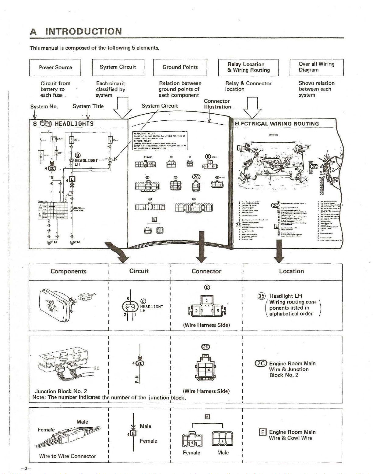
INTRODUCTION
This manual is
Power
Circuit
battery
each fuse .
co~posed
Source
from
to
of
the foll
System
Each
classified
system
owing 5 elements
Circuit
ci reu
it
by
EE3QIm
~I
liILJ')illi1
.
Ground Poi
Relation between
ground
each
System
Circuit
0-
®
®
points
component
®
~
®
g
nts
of
~
~
®
i
..
Connector
Illustral:ion
@-
d:b
®--
@
Relay Location
& Wiring
Relay &
location
Routing
Connector
"-'
- - ''''
. -
,-_
.....
Over
all Wiring
Diagram
Shows relation
between each
system
'-
-
~
lID
r---o
1m
®
I
I
J;;:~-
. -
--
-
'---
!
i
I
I
·1
1
I
i
Components
~'~~~2
Junction
Note:
The
Block.
number
No.2
indicates
Male
Circuit
2 I
~
2C
~2C
:
I
.
%
~
,
I
1
the
number
• E
of
the
@
HEADLIGHT
lH
junction
Male
Female
Connector
@
(Wire Harness Side)
®
I
I
I
I
I
I (Wire Harness Side)
block.
Location
® Headlight
Wiring routing com- )
ponents
(
alphabetical
<m
Engine Room Main
Wire &
Block No. 2
II]
Engine Room Main
Wire & Cowl
LH
listed in
order
Junction
Wire
-2-
Wire
to
Wire Connector
Female
Male
14
@-
~
REAR
- -----i>
HINDDH
DEfOG
'"
CB
DEFDGGER
OEFDGGER
CLOSED
AMO
OEfOGGff'l SIlt
NITH
RELAY
IGttITICIN
ON
@@SLACK
SIll
AT
1&
POSITIClH
""<~-----
".-
--
-@
--©
A
@-
--"""'"
®--
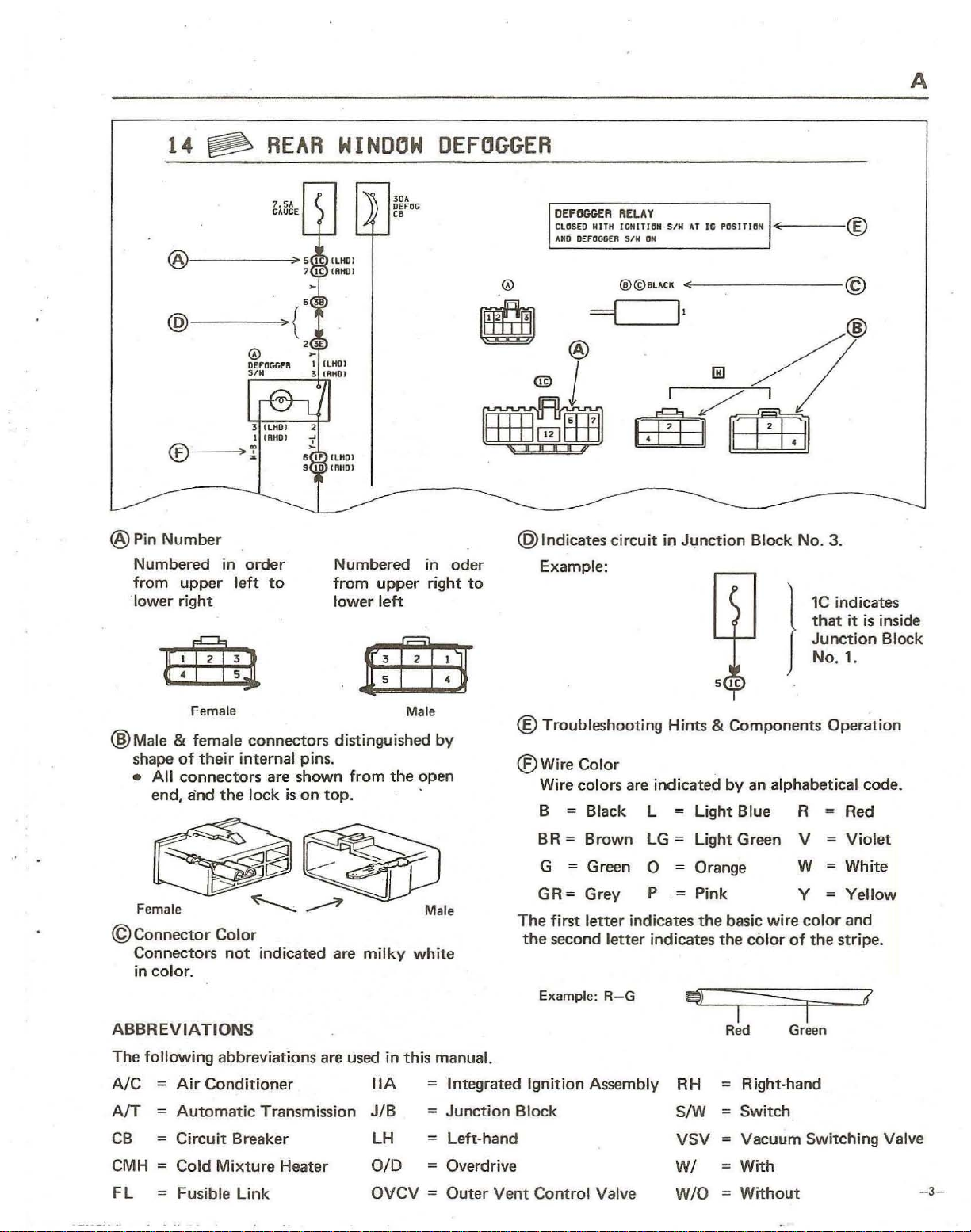
@PinNumber
Numbered
from
"lower right
~
~
@Male
©
ABBREVIATIONS
& female
shape
•
All
end,
Connector
Connectors
in
color.
in
upper
of
Female
their
left
internal pins.
connectors
and
the
Color
not
order
to
Numbered
from
upper
lower left
~
.D:E
Male
connectors
are shown from
lock
is
indicated are milky white
distinguished by
on
top.
the
in
right
open
oder
to
@Indicates
circuit in
Example:
@Troubleshooting
®Wire
Color
Wire colors are indicated
;
B
Black L Light Blue R
BR;
GR;
The
the
Brown
; Green
G
Grey P
first
letter
second letter indicates
Example:
LG;
0
indicates
R-G
Junction
Hints &
Light Green
Orange
;
Pink
the
the
I$)
Block
No.3
)
Components
by
an alphabetical
V
W
Y
basic wire
color
I
Red
color
of
I
Green
.
1C
indicates
that
it
is
Junction
No.1
.
Operation
code
;
Red
;
Violet
;
White
;
Yellow
and
the
stripe.
I{
inside
Block
.
The
following abbreviations are used in
;
AIC
AfT
CB
CMH
FL
Air Conditioner
;
Automatic
;
Circuit Breaker
Transmission
Cold Mixture Heater
Fusible Link OVCV ;
IIA
JIB
LH
OlD
this
manual.
;
Integrated Ignition Assembly
;
Junction
;
Left·hand
;
Overdrive
Outer
Block
Vent Control Valve
RH
S/W
VSV
WI
W
IO
;
Right-hand
;
Switch
;
Vacuum Switching Valve
;
With
;
Without
-3
-
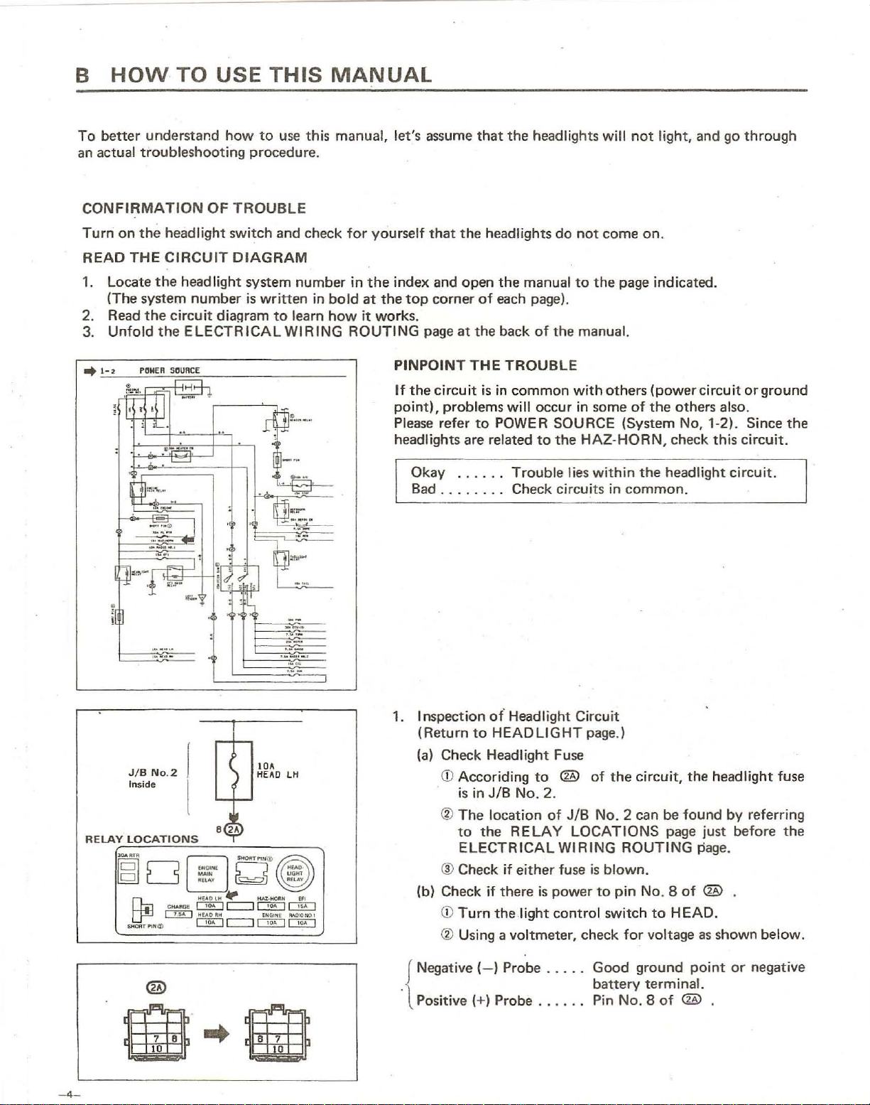
B
To
an
HOW
better
actual
understand
troubleshooting
TO
USE
how
procedure.
THIS
to
use
MANUAL
this manual, let's assume
that
the
headlights
will
not
light,
and go
through
CONFIRMATION
Turn
on
the
headlight switch and check
READ
1. Locate
2. Read
3.
..
THE
CIRCUIT
the
headlight system number in
(The system
the
Unfold
1-
~
I"t1NEfI
~
,,,
"""S1
i~',
'1b~!
'-::l:I
,
•
,
number
circuit
the
ELECTRICAL
SOURCE
.J
..
:""
")';"'~'"
1;<1..,
- _
11:/0
••
OF
TROUBLE
DIAGRAM
is
written
diaQram
~r9"
to
learn
WIRING
""
"
in
for
the
bold
at
how
it
ROUTING
yourself
the
works.
that
the
index and open
top
corner
page
PINPOINT
If
the
circuit
point),
Please
headlights are related
Okay ....
Bad
of
at
the
THE
problems
refer
to
........
headlights do
the
manual
each page).
back
of
TROUBLE
is
in
common
will
POWER SOURCE (System No, 1-2). Since
..
Trouble
Check circuits in
not
come on.
to
the
the manual.
with
others
occur in some
to
the
HAZ-HORN,
lies
within
page indicated.
(power
of
the
the
common.
circuit
others also.
check
headlight
this
circuit.
or
circuit.
ground
the
1.
Inspection ot' Headlight
JIB
In
side
No
.2
lOA
HE
(Return
(a)
.... O lH
(b) Check
to
HEADLIGHT
Check Headlight
<D
Accoriding
is
in JIB NO. 2.
®
The
location
to
the
RELAY
ELECTRICAL
® Check
<D
Turn
if
there
the
if
either
light
® Using a voltmeter, check
Negative
.
{
Positive (+) Probe
-4
-
(-)
Probe
Circuit
Fuse
to
@
of
JIB
LOCATIONS
WIRING
fuse
is
power
control
...
. .
...
_ . . Pin
page.)
of
the
No_
is
blown_
to
pin No.8
switch
Good
battery
No.8
circuit,
2 can
be
page
ROUTING
of
to
HEAD.
for
voltage
ground
terminal.
of
@ .
the headlight fuse
found
by
referring
just before
page_
@ .
as
shown
point
or
the
below.
negative
B
I eATTOIT 10
+
TAil
~
LOI<
~'"'~
"11;11
c;;;;~
FLASH
II
..
~
..
1
....
--
•
~;,
r--->-f--"'-''-------i
»'
---
---
'"
.
-,
'1'
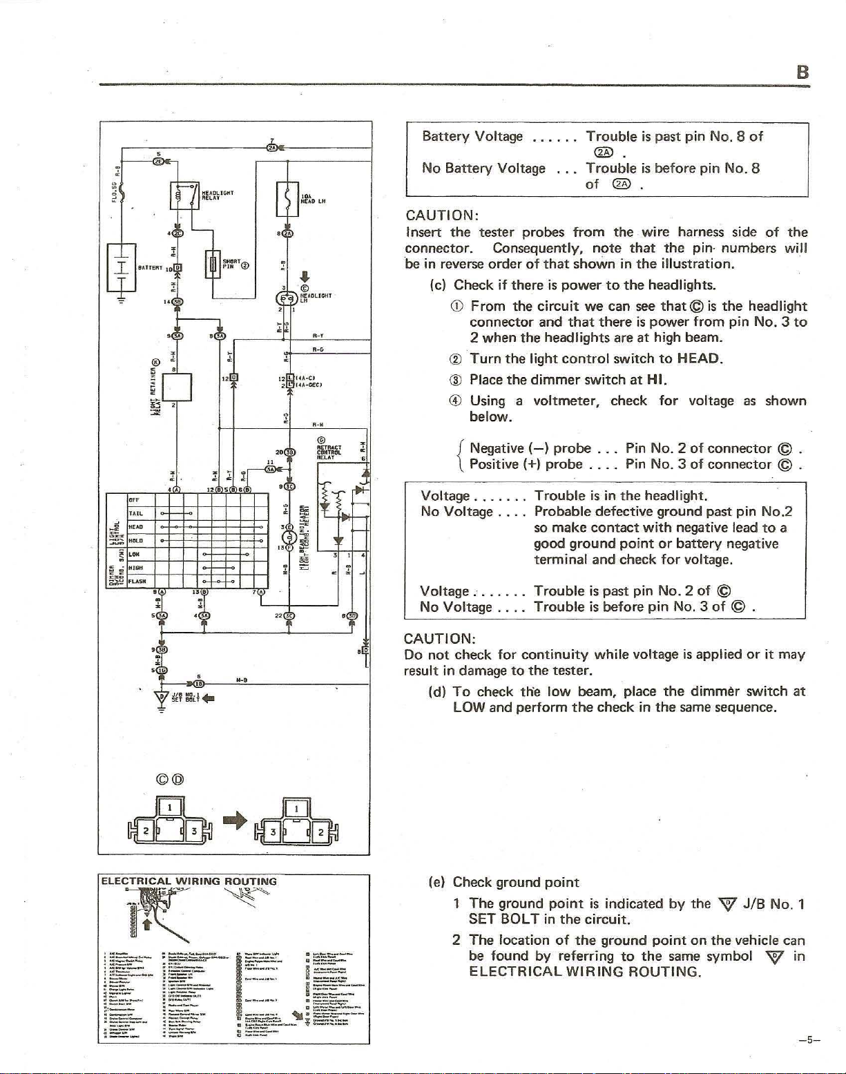
Battery
No
Battery
rtl
..
,
L-tJNfAn
lH
CAUTION:
I nsert
connector. Consequently,
be in reverse order
the
(c) Check
<D
~.
@
12 l
2
~
IU-CI
I~._IZCJ
® Place the
® Using a
,-.
·
@
IIUIlAU
CIIIHML
20~3~
"ElAT
,
•
"
9~P
•
,$:~~
~
•
"j
~
~~
-
,
,
.
.
"
•
"
, "
Voltage
No
Voltage ... . Probable defective ground past
Voltage
No
Voltage
CAUTION:
Do
not
result
in
(d)
Voltage
tester probes
From
connector and
2 when the headlights
Turn
below.
Negative
{
Positive
.......
........
check
damage
To
check th'e
LOW and
......
Voltage
if
there
the
the
.... Trouble
for
to
perform
...
of
that
is
power
circuit
that
light
control
dimmer
voltmeter,
(-)
probe
(+) probe
Trouble
so
make
good
terminal and check
Trouble
continuity
the
tester .
low
Trouble
®.
Trouble
of
®.
from
the ·
note
that
shown
ground
beam, place
the
in
to
the
we
can
there
are
switch
switch at
check
. . .
Pin
...
.
Pin
is
in
the
contact
point
is
past
is
before
while
check in
is
past pin
is
before
wi
re
harness side
the
the
illustration
headl ights.
see
that © is
is
power
at
high beam .
to
HEAD.
HI.
for
No.2
No.3
headlight.
with
negative lead
or
battery
for
pin
No.2
pin No. 3
voltage
the
the
NO.8
pin
No_
pin- numbers
.
the
from
pin
voltage
of
of
voltage.
of
is
applied
dimmer
same
as
connector © .
connector © .
pin
negative
©
of
© .
sequence.
of
8
of
the
will
headlight
No.3
to
shown
No.2
to
a
or
it
may
switch
at
©@
(e) Check ground
1 The ground
SET
BOLT
2 The location
be
found
ELECTRICAL
point
point
in
the
of
by
referring
is
indicated
circuit.
the
ground
WIRING
by
point
to
the
same
ROUTING.
the W JIB
on
the vehicle can
symbol W
No
. 1
in
-5-
B
HOW
" ,-,
JIB
'''''
..
'
''''
'M
'M
' M
~
No.2
.
POWER
(Engine
p,-
HEAD
LH
HEAO
RH
ENGINE
RADIO
NO.
HAZ·HORN
TO
Room)
1
USE
SOURtE
H~ldlighl
LH
Hudlight RH
Alt~niltOr
.
C/w'ge lit,Jht
Fuel Cui Solenoid, Em
E8CV, CUH ReI.,-,
Radio a
nd
T""e
Ho
rn
Haza
...
:1
SIW,
THIS
(Power-load
L
Re
issoion
~
Player
Tum
Signa!
FIWo«
MANUAL
Refe
....
l~
14A-C1
Cotmul Com
S100r
Cui
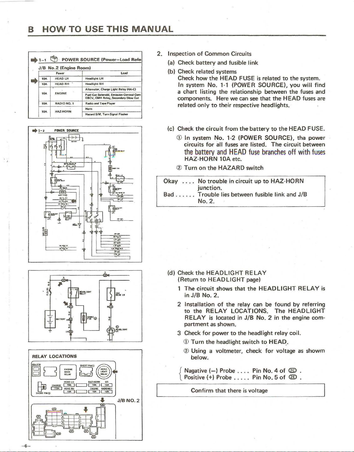
2.
Inspection
Check
(a)
of
Common
battery
(b) Check related systems
Check
a
In
chart
how
system
listing
the
No.
components.
related
only
to
Circuits
and
fusible I
ink
HEAD FUSE
1-1
(POWER
the
relationship
Here we can see
their
respective headlights.
is
related
SOURCE),
between
that
the
to
the
system.
you
will find
the
fuses
and
HEAD fuses are
r
I
RELAY
: •
..
_ ...
--
LOCATIONS
___
-
,
"
"
Check
(c)
CD
m
®
Okay
the
In
system
circuits
the
battery
HAZ
·HORN
Turn
...
.
circuit
from
No. 1·2 (POWER
for
all fuses are listed.
and
lOA etc.
on
the
HAZARD
No
trouble
the
HEAD
switch
in circuit
battery
fuse
branches
up
to
to
the
HEAD FUSE.
SOURCE),
The
circuit
off
HAZ·HORN
tha
power
between
with
fuses
junction.
Bad
....
Trouble
. .
lies
between
fusible link
and
JIB
No.2.
.
~
(d) Check
(Return
1
2 Installation
3 Check
the
HEADLIGHT
to
HEADLIGHT page)
The
circuit
in JIB No.
to
the
RELAY
partment
CD
Turn
shows
2.
of
the
RELAY
is
located
as
shown.
for
power
the
headlight switch
that
relay
LOCAT.IONS.
in
to
the
® Using a voltmeter,
RE
LAY
the
HEADLIGHT
can
JIB
No.2
headlight
to
check
be
found
The
in
relay coil.
HEA~
for
voltage as
RELAY
by
referring
HEADLIGHT
the
engine
.
showm
is
com·
below.
,---------"
-6-
...
r---...
JIB
NO.2
Nagative
{
Positive
Confirm
(-)
(+)
Probe . .
Probe
that
there
..
....
. Pin No. 5
is voltage
Pin
No.4
of
of
® .
<ill .
B
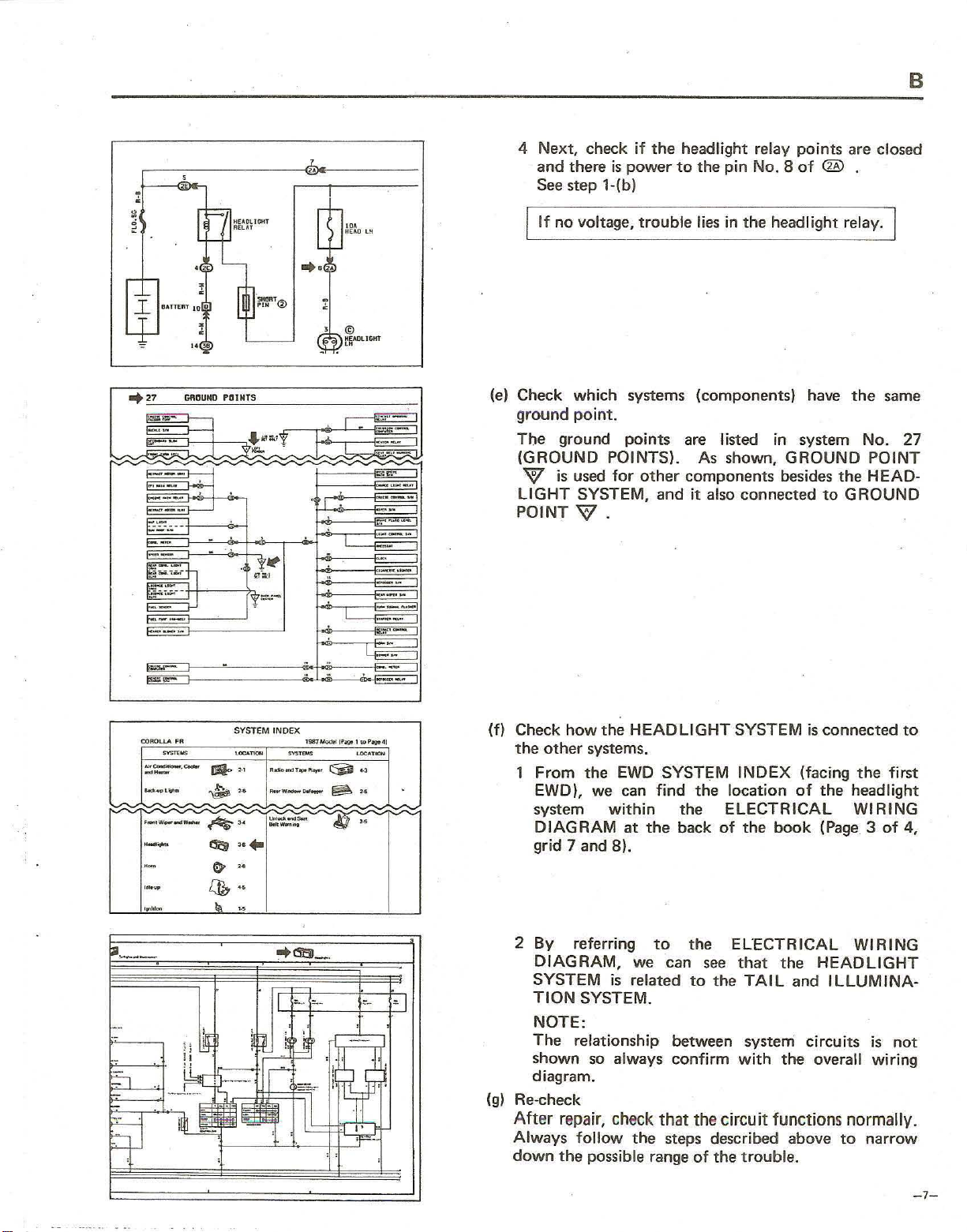
4
"8
2~
Next,
and there
See
If
check
is
power
step
l-(b)
no voltage,
if
the
headlight relay
to
trouble
the
pin
lies in
points
No. B
of
the
headlight relay.
are closed
®
l
, ©
~ADlI&lll
(e)
..
27
~OUND
PClINTS
::'1" -
.""
Check
ground
The
(GROUND
W
LIGHT
POINT
which
point.
ground
is
used
SYSTEM, and
systems (components) have
points
POINTS). As shown,
for
W.
are
listed in system No. 27
other
components besides
it
also connected
GROUND
the
to
GROUND
the
POINT
HEAD-
same
COROLLA FR
~~
::;0;::.-
-,-
._'"
....
-
-
-.
-
,~
--
SYSTEM INDEX
=-
-'l
., n_
,.
~
A-~
..
..
(!til
H
&
"
,
.,
~
1967_,PoQe,,,,roge.,
SYST
....
C'j;ll .,
...
'_
........
---
---
--
§l.
"""
-if
'-OC~1"'"
,.
,.
't:"
(f)
Check
the
1
2
(g)
Re-check
After repair,
Always
down
how
the
HEADLIGHT
othe
r systems.
From
EWD), we
system
DIAGRAM
grid 7 and
By
DIAGRAM,
SYSTEM
TION
NOTE:
The relationship between system
shown
diagram.
the
EWD SYSTEM
within
B)
referring
is
SYSTEM.
so
always
check
follow
the
possible range
can
find
the
at
the
back
.
to
we can
related
confirm
that the circuit functions normally.
the
steps described above
SYSTEM
INDEX
the location
ELECTRICAL
of
the
the
ELECTRICAL
see
that
to
the
TAIL
with
of
the
trouble
book
the
the
is
connected
(facing
of
and
circuits
.
the
the
headlight
WI
(Page 3 of
WIRING
HEADLIGHT
ILLUMINA
overall
to
to
first
RING
4,
is
not
wiring
narrow
·
-7-
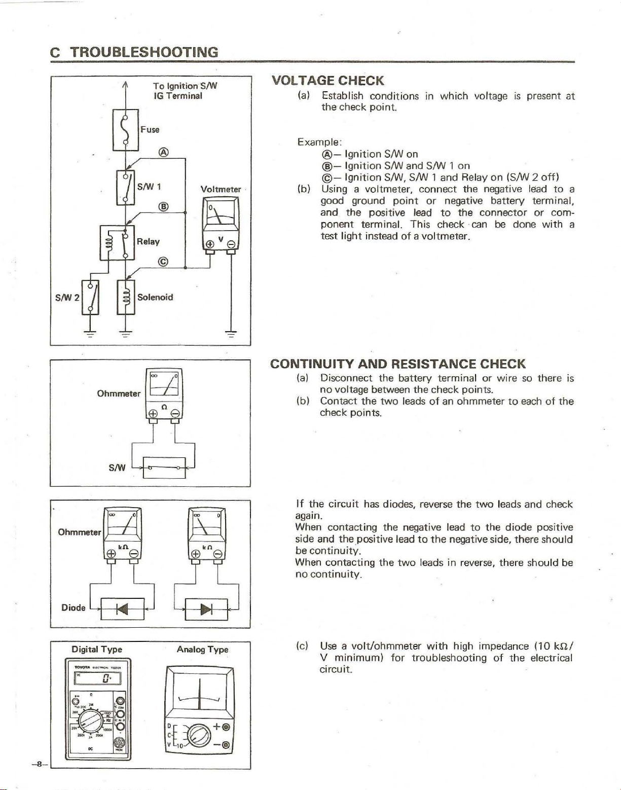
C
TROUBLESHOOTING
SIW2
r
'-
,--,
:
~
/
'-t-
~
'-I
-:?-
Ohmmeter
-
(
~
L
0
,/
;;
~
To
IG
Terminal
Fuse
@
SIW ,
@
Relay
©
Solenoid
~
n
+ e
Ignition
S/W
Voltmeter
l±::
@Ve
T
--=
VOLTAGE CHECK
(a)
Establish conditions in
the
check
Example :
@@-
©-
(b) Using a voltmeter, connect the negative
good ground
and
ponent terminal. This check ·
test
CONTINUITY
(a)
Disconnect the
no
voltage between
(b) Contact
check points.
Ignition
Ignition
Ignition
the
light
inst
AND
the
point.
SNJ on
SNJ and
SNJ, SNJ 1 and Relay
point
positive
ead
of a voltmeter.
RESISTANCE CHECK
battery
two
leads
which
SNJ
or
lead
to
terminal
the
check
of
an ohmmeter
1
on
negative
the
points
voltage
on
(SNJ 2
battery
connector
can
be
or
wire
.
is
present at
off)
lead
terminal,
or
done with
so
there
to
each
of
to
a
com·
a
is
the
SIW
~
~
-,
Ohmmeter~~~
Diode
'-I
-8-
-~-
Digital
Type
1'OoOU ....
<-..0
",,,.
a·
!"
<§~:
I~@'-~
-
..
-
~
I
~
~
II
-
-I-'
D{~+@
~
r
EEl
Analog
10
~
kn
e
Type
-@
If
the
circuit
again.
When conta
side and
be
continuity.
When contacting
no
continuity.
(c)
Use a volt/ohmmeter
V
circuit
.
has
diodes, reverse the
ct
ing the negative lead
the.positive lead
the
two leads in reverse, there s
minimum)
.
for
two
to
to
the
negative side, there should
with
high impedance
troubleshooting
leads and check
the
diode
of
the
positive
hould
(10
electrical
be
knl
c
Test Light
Disconnect
\
Light
SIW 2
,-----...,
=
To
tG
Fuse Case
SIW 1
~Disconnect
r---1o,
Relay
Solenoid
Ignition SIW
Terminal
Short@
Short@
Short@
Disconnect
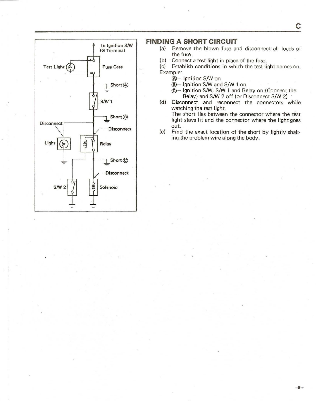
FINDING
(a)
(b)
(c)
Example :
(d) Disconnect and reconnect
(e)
A SHORT
Remove
the
Connect a test lig
Establish
@@-
@-
watching
The
light
out.
Find
ing
the
blown
fuse.
conditions
Ignition
Ignition
Ignition
Relay) and SIW 2
short I
stays
the
the
SIW on
SIW and SIW 1 on
SIW, SIW 1 and Relay
the
test light.
ies
between
lit
and
exact
problem
CIRCUIT
location
fuse and disconnect all loads
ht
in
place
of
the
fuse.
in
which
off
the
connector where
wire
along the
the
test
on
(or
Disconnect SIW 2)
the
connectors
the
connector
of
the
short
body.
light
(Connect
where
the
by
comes on.
the
light
lightly
of
the
while
test
goes
shak-
=
-9-
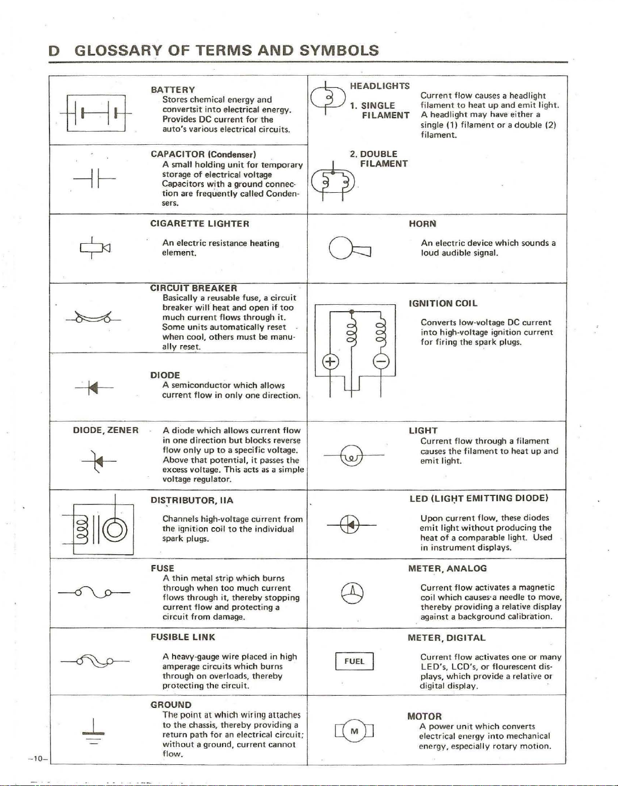
D
GLOSSARY
OF
TERMS
AND
SYMBOLS
,
-lEE-
---H
-
~
~
I
~
BATTERY
Stores
chemical
convertsit
Provides
auto's
various
CAPACITOR
A smal'!
storage
Capacitors with a
tion
sers.
CIGARETTE
An
element. loud audible signal.
CIRCUIT
Basically a reusable fuse. a circuit
breaker
much
Some
when
al
DIODE
A
current
holding
of
are
frequently
electric
BREAKER
will-
current
units
cool,
ly reset_
semiconductor
flow in only
energy
into
electrical
DC
current for the
electr
(Condenser) 2.
electrical voltage
LIGHTER
resistance heating
heat
flows
automatically
others
and
energy.
ical circuits.
unit
for
temporary
ground
and
whicl:l allows
called
open
through
must
one
connec-
Conden-
reset
be
direction.
if
it.
manu-
$
cp
too
HEADLIGHTS
1.
SINGLE
FILAMENT
DOUBLE
,
FILAMENT
Ch
~
+
L
W
~
g
e
Current
fi
lam
A
headlight
single
filament.
HORN
An
electric
I
GNITION
Converts
into
for
firing
flow
ent
to
(1)
filament
device which
COIL
low-voltage
high-voltage ignition
the
causes
heat
up
may have
or a
spark
a headlight
and
emit
either
double
sounds
DC
current
current
plugs_
light.
a
(2)
a
-10
DIODE,
+
-
~
~
~
---O\..J>----
~
..L
---
-
-
ZENER
II©
A
diode which
in
one
direction
flow
only
Above
that
excess voltage. This
voltage
DISTR I BUTOR,
Channels high-voltage
the
igni
tion
spark plugs.
FUSE
A
thin
metal
through
flows
through
rurrent
circuit
from damage, against a
FUSIBLE
GROUND
LINK
A heavy-gauge wire placed in high
ampe
rage circuits
through
protecting
The
point
to
the
chassi
return
path
without a ground,
flow.
allows
curre
but
up
potential,
regulator
coil
when
flow and
on
overloads,
the
at
which wiring
s,
for an electrical circuit;
blocks
to
a specific voltage.
it
passes
acts
current
the
individual
which
much
thereby
prot
ecti
which
thereby
providing a
current
as a simple
burns
current
stopping
ng a
burns
.
IIA
to
strip
too
it,
circuit_ digital display .
thereby
nt
flow
reverse
the
from
attaches
cannot
-Q-
®
0)
FUEl
I
c8J
I
'
LIGHT
Current
caus es
e
LED
Upon
em
heat
in
METER,
Current
coil
thereby
METER.
Current
LEO's,
plays,
MOTOR
A
e
energy, especially
flow
the
mit
light.
(L1GI:lT
current
it light
of a comparable
instrument
ANALOG
flow activates a
which
providing a relative display
background
DIGITAL
flow activates
LC~'s,
which provide
pow
er unit
le
ctrica
l energy
through
filame
EMITTING
flow, these
without
displays.
causes'a needle
which
a filament
nt
to
heat
producing
light. Used
calibration.
a relative or
converts
into
mechanical
rotary
one
or flourescent di
up
DIODE)
diodes
the
magnetic
to
move,
or
many
motion.
and
s-
o
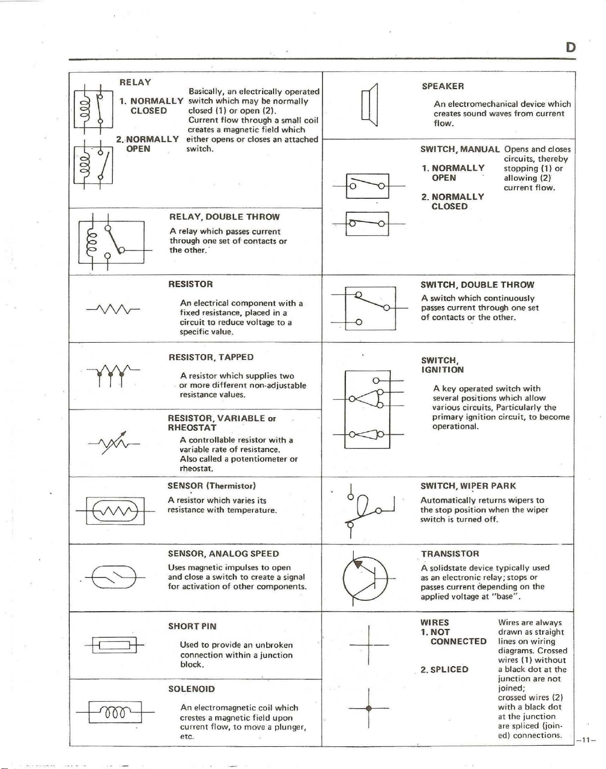
RELAY
.
liD
rtZl
. OPEN
I I
~
T
---A,/\/'v--
.
-yyy-
CLOSED
'
'0"""
'
..
0._'"
~\
I
-yfv-
Basically.
switch
closed
Current flow
creates a
either
switch .
RELAY,
A relay
through
the
other.
RESISTOR
An electrical
fi
xed resistance. placed in a
circuit
specific value.
RESISTOR, TAPPEO
A resistor
.
or
more
resistance values.
RESISTOR,
RHEOSTAT
A
controllable
variable
Also
rheostat.
which
11)
magnetic
opens
DOUBLE
which
one
set
to
reduce
which
different
VARIABLE
rate
called a
an
electrica
may
or
open 12).
through
or
passes
of-contacts
component
resistor
of
resistance.
potentiometer
lly
operated
be
normally
a small coil
field
an
current
or
with
which
attached
or
with
to
a
two
a
or
closes
THROW
voltage
suppl ies
non-adjustable
SPEAKER
An
~
+~
electromechanical device
creates
sound
flow.
SWITCH,
1.
2.
MANUAL
NORMALLY
OPEN
NORMALLY
CLOSED
waves
from
Opens and close,
circuits,
stopping
allOl.1'
current
current
ing
flow.
which
thereby
(1)
or
12)
++
SWITCH,
switch
a
A
pas
of
which
"ses
current
contacts
DOUBLE
continuous
thro
or
the
THROW
ugh
one
other.
ly
set
fi
SWITCH,
IGNITION
A
key
operated
several
t
~
.
~.
positions
various circuits, Particularly
primary
operational.
switch
which allow
ignition circuit,
with
to
the
become
I (/\/V) I
·
-E>+
--8
8-
-f--'ooo+
SENSOR
A resistor
resistance
SENSOR,
Uses magnetic impulses
and
for
SHORT
SOLENOID
IThermistor)
which
with
ANALOG
close a switch
activation
PIN
Used
to
provide
connection
block.
An ele
ctromagnetic
crestes a
current
etc
magnetic
flow.
.
varies its
temperature.
SPEED
to
create
of
other
an
within a junction
to
move
to
open
a signal
components.
unbroken
coil which
field
upon
a plunger.
SWITCH, WIPER
Automatically
the
stop
switch
~J
QJ-
is
TRANSISTOR
A solids
as an
passes
applied voltage
WIRES
1.
tate
electronic
current
NOT
CONNECTEO
-1-
2.
SPLICEO
+
returns
position
turned
device
depending
PARK
wipe
when
off.
rel
at
ay;
"base"
typically
rs
the
wipe
stops
on the
.
Wires are always
drawn
as straight
lines
on
diagrams. Crossed
(1)
wires
a black
junction
joined;
crossed wires (2)
with a black
at
are
ed)
dot
the
junction
spliced (join.
connections.
to
r
used
or
wiring
wi
thout
at
are
-
the
not
dot
-11-
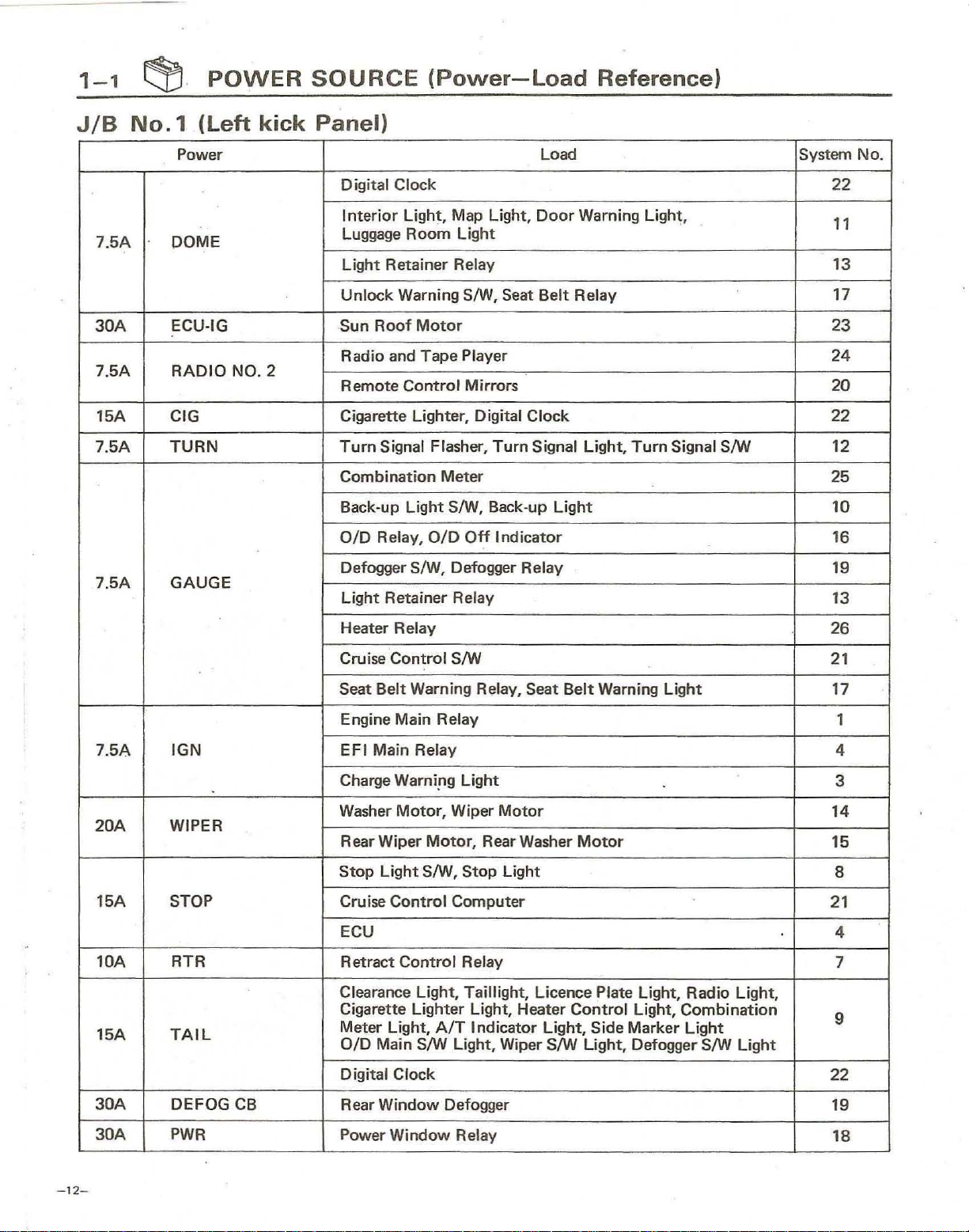
1-1
~
.
POWER
SOURCE
(Power-Load
Reference)
JIB
No.1
Power Load System No.
7.5A
30A
7.5A RADIO
15A
7.5A TURN
7.5A GAUGE
DOME
ECU-IG
CIG
(Left
NO_
kick
2
Panel)
Digital Clock
Interior Light, Map
Luggage Room Light
Light Retainer
Unlock Warning S/W, Seat Belt Relay
Sun
Roof
Motor
Radio and
Remote
Cigarette Lighter, Digital Clock
Turn
Combination Meter
Back-up Light
OlD Relay,
Defogger
Light Retainer
Tape
Contro
Signal Flasher, Turn Signal Light,
OlD
S/W, Defogger Relay
Lig
ht,
Door
Relay
Player
I Mirrors
S/W, Back-up Light
Off
Indi
cator
Relay
Warning Light,
Turn
Signal S/W 12
22
11
13
17
23
24
20
22
25
10
16
19
13
Heater
Cruise Control S/W
Seat
Engine Main
I
7.5A
20A
15A STOP
lOA RTR Retract Control Relay
15A
GN
WIPER
TAIL
EFI Main Relay
Charge
Washer
Rear Wiper Mo
Stop
Cruise Control Computer
ECU
Clearance Light, Taillight, Licence Plate Light, Radio Light,
Cigarette Lighter Light, Heater Control Light,
Meter Light,
OlD Main S/W Light, Wiper S/W Light, Defogger S/W Light
Digital Clock
Relay
Belt Warning Relay,
Relay
Warniflg Light
Moto
r,
Wiper Motor
tor,
Rear Washer
Light S/W, St
op
A/T
I ndicator Light,
Seat
Light
Belt Warning Light
Mot
or
Combination
Side
Marker Light
26
21
17
1
4
3
14
15
8
21
4
7
9
22
30A DEFOG
30A
-
12-
PWR
CB
Rear Window Defogger
Power Window Relay
19
18
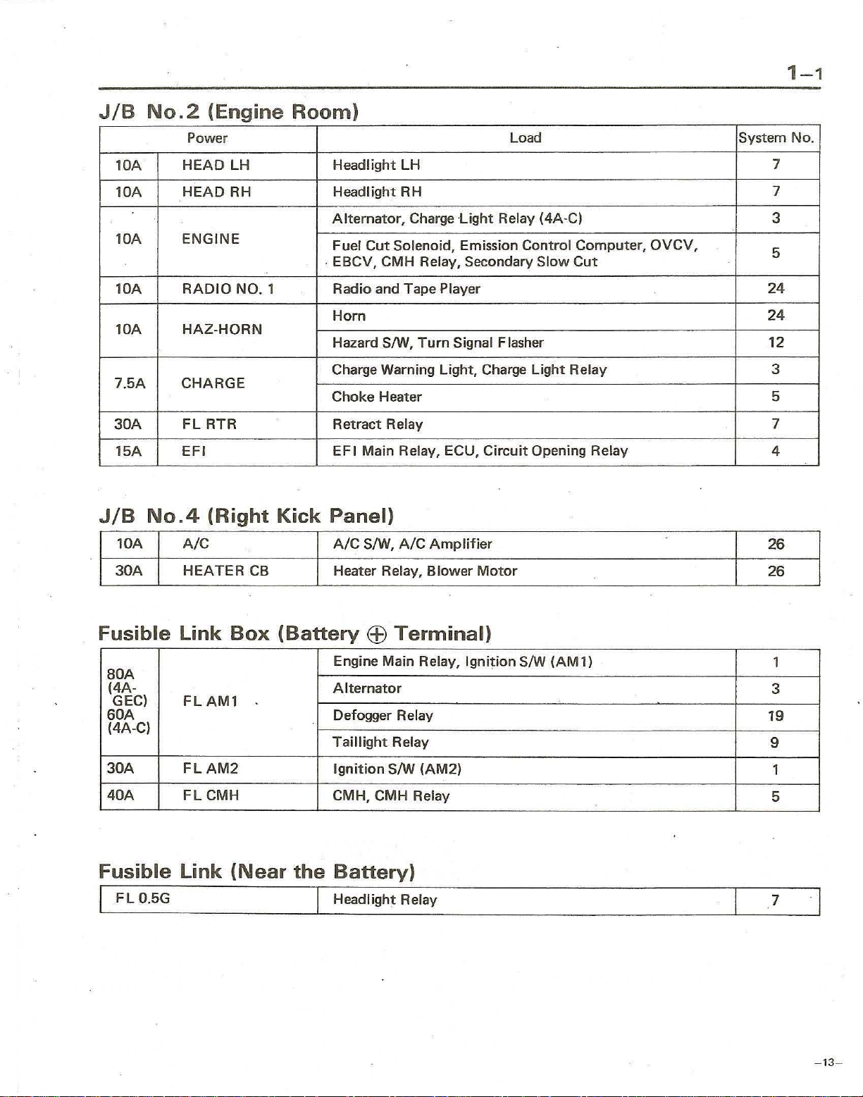
1-1
JIB
lOA
lOA
lOA
lOA
lOA
7.5A
30A
15A
JIB
No.2
No.4
(Engine
Power Load
HEAD
HEAD
ENGINE
RADIO
HAZ·HORN
CHARGE
FL
EFI
LH
RH Headlight RH
NO.1
RTR Retract Relay
(Right
Room)
Kick
Headlight
Alternator,
Fuel
. EBCV, CMH Relay, Secondary
Radio and Tape Player
Horn
Hazard SIW,
Charge Warning Light, Charge
Choke Heater 5
EFI
LH
Charge
Cut
Solenoid, Emission
Turn
Signal Flasher
Main Relay, ECU,
Panel)
Light
Circuit
Relay (4A·C)
Control
Slow
Cut
Light
Relay 3
Opening Relay
Computer,
OVCV,
System No.
7
7
3
5
24
24
12
7
4
lOA
30A
A/C
HEATER
Fusible Link
aOA
(4A·
GEC)
60A
(4A·C)
30A
40A
FLAMl
FLAM2
FL
CMH
Fusible Link
I F L
O.5G
CB
Box
(Battery
(Near
A/C
SIW,
Heater Relay,
EEl
Engine Main Relay,
Alternator
Defogger Relay
Taillight
Ignition
CMH, CMH Relay
the
Battery)
I Headlight Relay
A/C
Amplifier
Blower
Terminal)
Ignition
Relay
SIW
(AM2)
Motor
SIW
(AM
1)
26
26
1
3
19
9
1
5
7
I
-13-
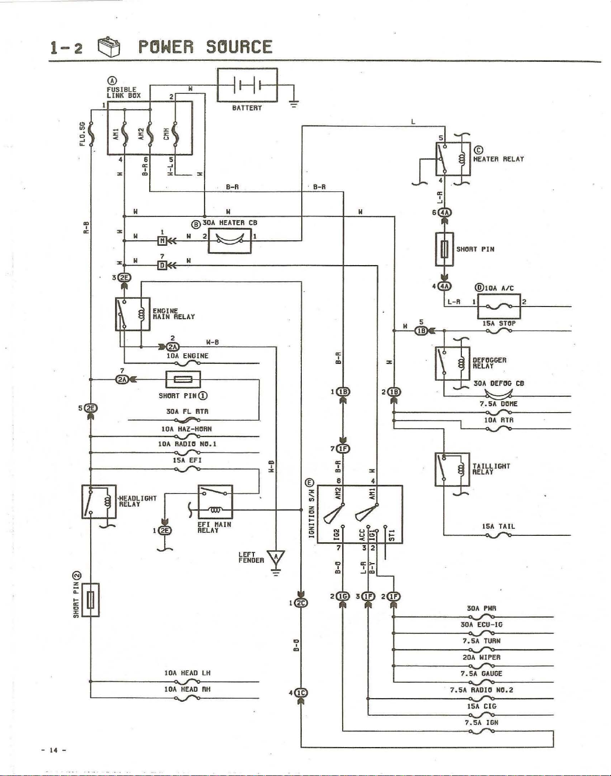
1-
2
POWER
SOURCE
@
z
~
~
D
'"
r
~
~
l
0
~
~
m
,
~
5
2E
0
FUSIBLE
LINK
I
;;;
1
< <
•
z m
z
z
3'
,0
1
r---®
,
HEADLIGHT
~
RELAY
->-
DUX
N
r r
W
H H
H
~
u
6 5
~
, ,
I
.!!.
1
..!!.
ENGINE
"AIN
2
~
z~z
RELAY
~
2.
iDA
I - J
SHORT
30'\
lOA
lOA flAOld
ISA EFl
I 2E
IDA
IDA
w
® 30A
H
ENGINE
PIH(j)
fL
ATR
HAZ
-Ha
(
T
H~
HEAD
:1-1'
BATTERY
B-R B-R
H H
HEATER
C:B
21
\.
A
II
I I
W-B
RN
NC.1
~
m
, ,
z m z
J
EFI
"AIN
RELAY
lH
RH
LEFT
FENDEA
A
::-
I
2C
D
,
m
• IC
~
,
m
I
IB
7
IF
~
® •
Z
,
~
z
E
~
z
~
N
r
<
N u
~
1
D
,
m
2
16
z
2 IB
•
;;;
<
u<>
<
3 2
~~
~fJ.
3 I F 2
;:
~
IF
HA-
L
5
0
1
r.
~
,
~
6
..
r
l!.
.~
L-R
..!!!.
..
--
©
HEATER
.-
....
SHORT
PIN
@IOA
.
11
I I
ISA SHIP
-r
DEFOGGER
RELAY
........
30'\.OEF~
SAD
1..
IDA
TAILLIGHT
RELAY
--
15,\
PHR
30A
30'\
fCU-IG
7.SA
TURN
20A WIPER
7.sA
GAUGE
7.SA
RADIO
15,\
eIG
7
.SA I6N
RELAY
A/C
12
CB
t!"E
fnR
TAIL
NrI.2
I.
-
I
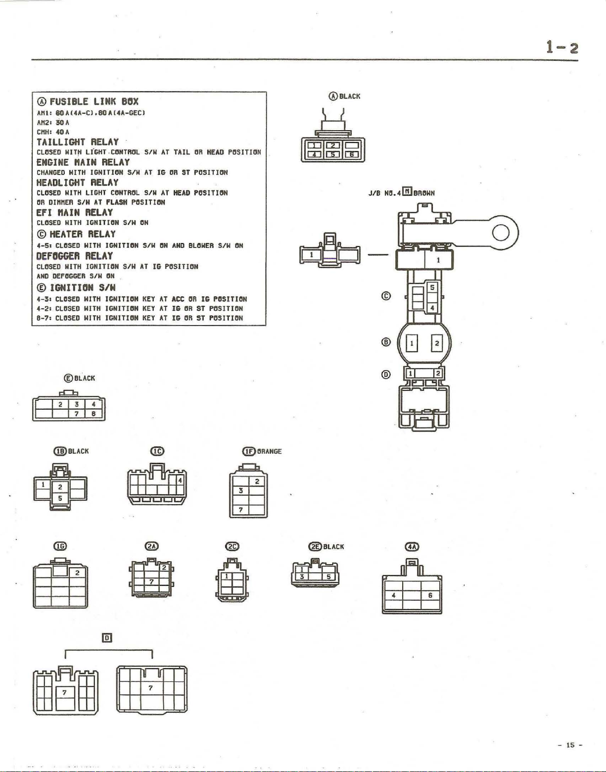
1-2
®
FUSIBLE
AtU
;
6OU4A-CI.80Al4A-GECJ
A"2:
50A
CrtH:
40
TAILLIGHT
CLOSED
ENGINE
CHANGED
HEADLIGHT
CLOSED
OR
DInMER
EFI "AIN
CLOSED
©
HEATER
4-5.
CLOSED
DEFOGGER
CLOSED
AND
DEfOGGER
®
IGNITION
4-31
CLOSED
4-2:
CLOSED
8-7:
CLOSED
®BLACK
LINK
A
RELAY
WIT~
LIGHT.CONTROL
"AIN
HITH
IGNITION
RELAY
NITH
LIGHT
SIN
AT
RELAY
NITH
IGNITION
RELAY
NITH
RELAY
MITH
IGNITION
SIN
HITH
HITH
HITH
BOX
RELAY
CONTROL
FLASH
SIN
IGNITION
SIN
ON
SIN
IGNITION
IGNITION
IGNITION
S/W
SIN
AT
SIN
POSITION
ON
SIN
AT
KEY
KEY
KEY
AT
IG
OR
AT
ON
IG
POSITION
AT
AT
AT
TAIL
Sf
HEAD
AND
ACe
IG
OR
IG
OR
OR
HEAD
POSITION
POSITION
BLOWER
OR
16
POSITION
ST
POSITION
ST
POSITION
POSITION
SIN
ON
®BLACK
JIB
NO.,[B]BROWN
ffJ=!=n-
©
@
@
o
@BLACK
®
@'RANG£
@BLACK
- 15 -
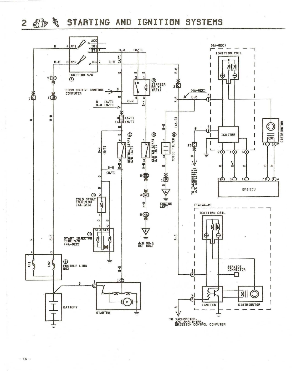
STARTING
AND
IGNITION
SYSTE
MS
• .B
o
'"
m
N
B-R
" A"l
8
A"2
IGNITIGN
®
. FAO" tAU I
COMPUTER
SIN
Sf
Ae
IG.
STl
IG
7
CONTfUll
B
8-M
_"""""
,.-::.B-+
__
(A/Tl
'H/TI
8-N
IT)
(H
B-N
m
8-N
)J
etc]
(All)
14[C] UVT)
m ©
•
3
~
,:,
UtlTJ
r2f-"~®
1
.1\
\'
•
3
~
o
m
STARTER
RELAY
(HITI
D
m
o
®
•
II-
2
m
o
~
8
3E
2 D
.[B]
("
r------,
D
o
m
"A-GEe)
D /
o'+-~-~~-(ID---;
m I
B-a
I
J.J
I
-
-,
@
:5
~
;::!
~
~
~
Z
u
o
<
~
B
I
~
I I
.--'--
I
A-GEt
)
IGHITHIN COIL
GNITER
L-r----,,-I
600
S L
--,
I(L)
•
o
'"
m
6
-'-
l
T
..L
1/
calD
INJECTOR
(4A-GEC)
START
INJECHIA
TIHE
SIN
(4A-GEt)
®
FUSI
BLE
BOX
BATTERY
LINK
B
@2
STAAT
®'
o
L
STARTER
2
~
o
m
• E
I
'---II-@-
• 3F
m
o
~
9 . A
E
JIB
NO
. 4
SET BlJlT
e
ENGINE
LEft
IIA(4A-C)
r----
I
I
D
0'
m
I
I
I
I
I
),J
F
\ I
TO
TACH""ETER.
Alt
EHISSION CGNTROl
'---1--
"HPLIFIER •
IGNITUIN COIL
"=
CGHPU1ER
EF I
------,
SERVICE
CI:INNECTGR
-0
DISTRIBUTOR
----..-.I
fCU
I
I
I
I
I
I
I
-
16
-
2
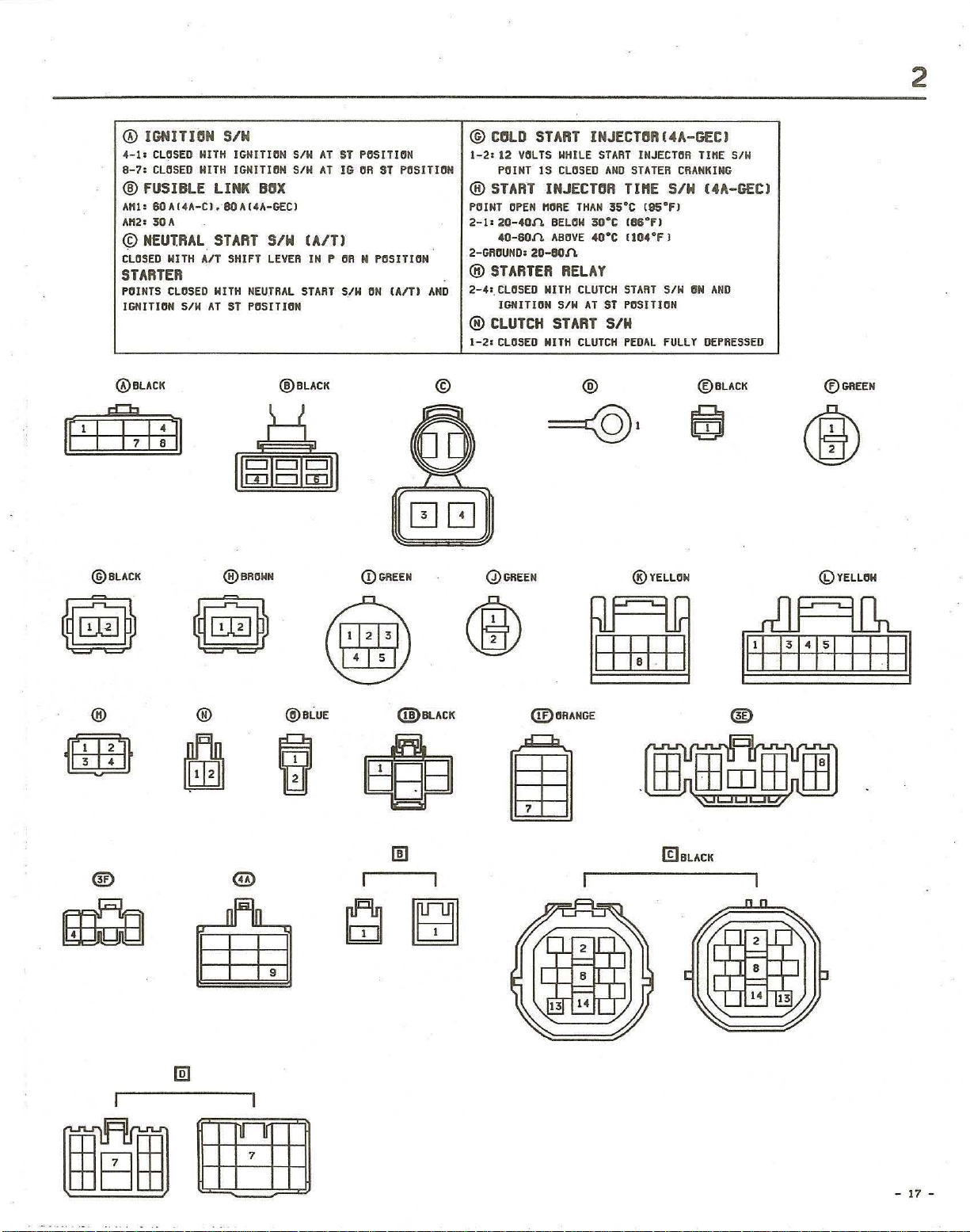
® IGNITlIIN SIN
4-1:
CL~SEO
8-7:
CUJSED
@ fUS I BlE LI
Att
l:
BOAl4"'-C).
Att2:
30A
©
NEUTRAL
CLOSED
STARTER
POINTS
IGNITION
®BLACK
['III:]
@BLACK
H
HITH
WITH
AIT
CLOSED
SIH
ITH
IGHITI~N
IGNITIrIN S/H
NK
80
"(4A
START
SHIFT
HITH
NEUTRAL
AT
S1
paSITION
SIH
AT
AT
BIIX
-GEe)
SIN IAlT!
LEVER
IN
START
@BLACK
ST
P~SITION
IG aft
P OR H
SIN
Sf
PtiSITI""
POSITION
aN
IAITI
@ ClllD
1-2:
®
POINT
2-1:
2-GROUNO: 20-801\
®
2-4:. CLOSED
AND
®
1-2:
©
START
12
VOLTS
POI
NT
15
START
INJEtTIlR TInE SIN (4A-GEt)
OPEN
"ORE
20-40/\
40-80.(1.
STARTER
NITH
IGNITION
CLUTCH
CLOSED
HITH
INJE
CTII
HHI
LE
START
CLOSED
AND
THAN
BEl
ABOVE
35·C (95°
ON
30°C 18SoF)
40·C
(104
RELAY
CLUTCH
AT
ST
SIN
CLUTCH
START
POSITION
PEDAL
SIN
START
@
=@,
R (4A-GEt)
INJECTOR
srATER CRANKING
FI
OF
J
SIN
fULLY
TI"E
aN
AND
DEPRESSED
@BLACK
~
S/W
®GREEN
®
"~!§lI~"
®BROHN
(DGREEN
Q)GREEN
® Y
ELLO
"
<DYELLO"
®
1liliJl.
~
®
®
®
@BLUE
@BLACK
@ORANG€
®
(£)BLACK
-
17
-
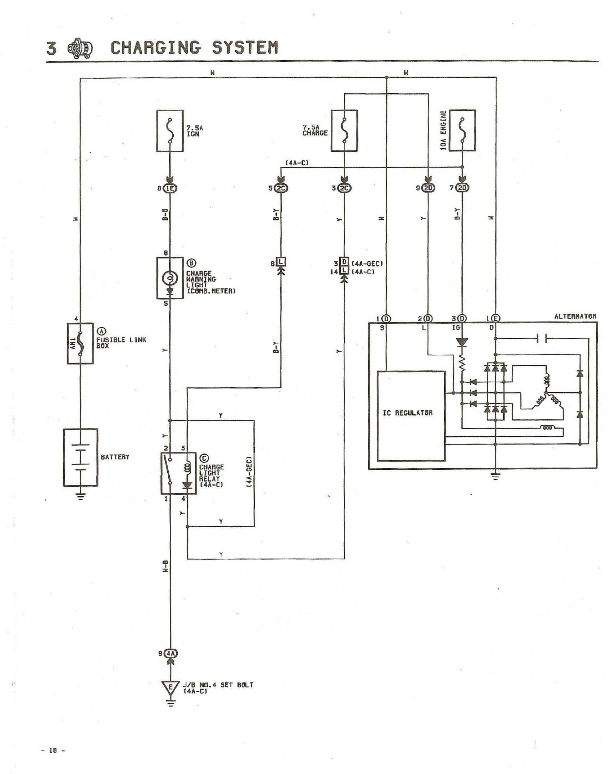
3
~
CHARGING
SYSTEM
H
H
%
--
o
FUSIBLE
.ox
LINK
r--
7.SA
IGN
'-
-
•
IE
,
"
..
6
,...;;-@
CHARGE
WARNING
~D
LIGHT
(trlflB.rtETER)
ICA-C)
set;
~
,
..
~
,
..
7.5"
CHARGE
I-
-
l-
-
3
2C
~
3[D]
14A-GECI
14~l~
14A-C)
~
%
1(0
s
9
2(0
w-
z
;;
z
w
)
<
e
f-
--
7
20
~
L
20
~
,
..
3(0)
IG
~
,
1
%
•
E)
ALTERNATtiR
,
, ,
-
I
_L
l
T
~
BATTERY
~
2 3
I
..
,
%
9
••
E
•
~
JIB
("A-C)
y
©
CHARGE
LIGHT
RELAY
I·
U-C)
y
y
NO.4
SET
U
w
'"
<
•
-
BrllT
~
'
...
.
-,
Ie
REGULA-HIR
I
,
-
18
-
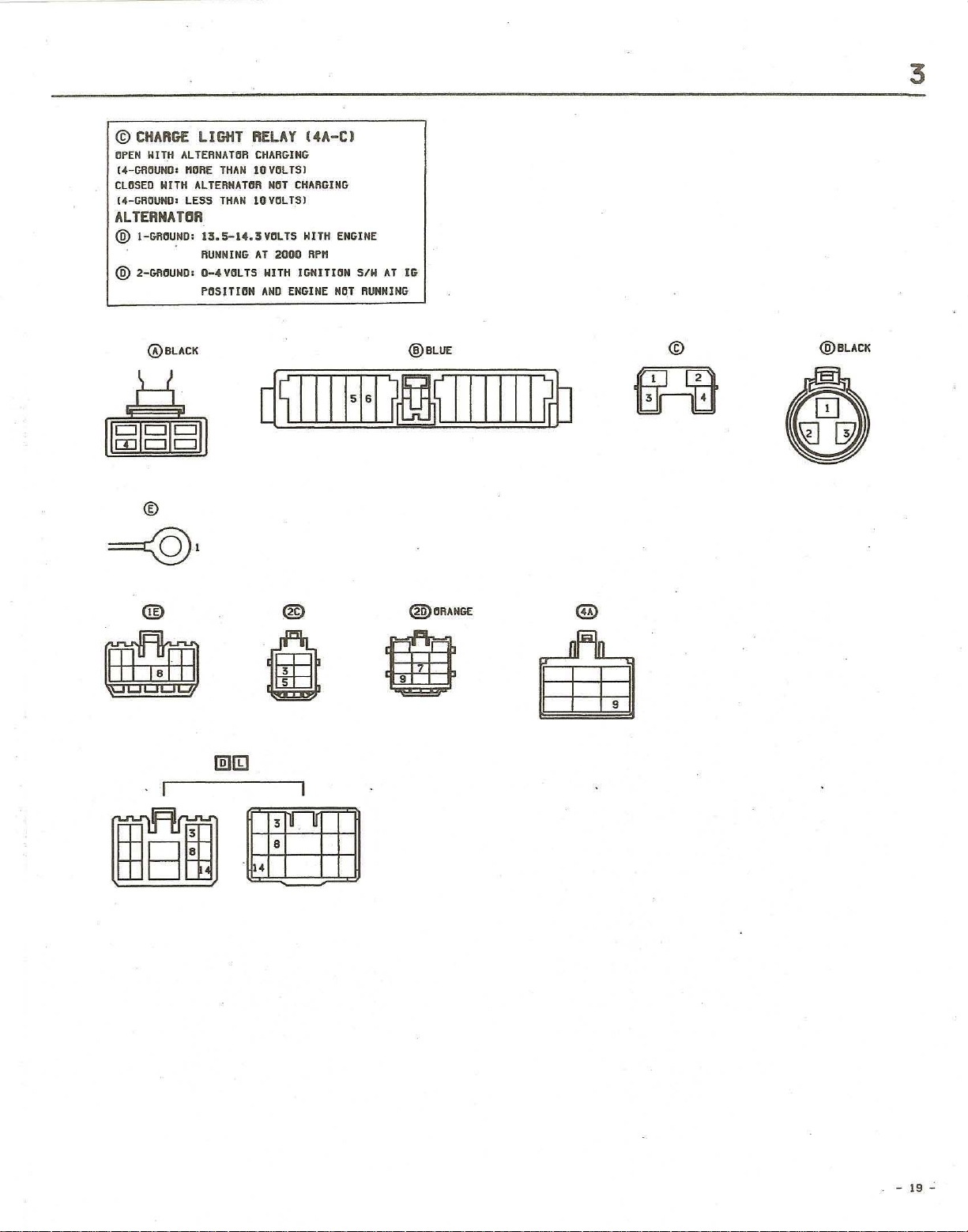
©
CHARGE
OPEN
KITH
("-GROUND I rtORE
CLOSED
14-GROUNDI
ALTERNATIIR
® I-GfU:IU,ND;
@ 2-GRCUNDI
LIGHT .RELAY
ALTERNATOR
NITH
ALTERNATOR
LESS
13.S-14.3VCJLTS
flUNNING
0-4VOLTS
rnSlTION
THAN
THAN
14A-CI
CHARGING
10VOLTSJ
NOT
CHARGING
10VCLTS)
HITH ENGINE
AT
2000
RPM
NITH IGNITION
AND
ENGINE
NO.1
SIN
AT
RUNNING
3
IG
@BLACK
I I
dtBle'J
CD
I I
=@l
® ®
a
@lib]
®BLUE
d~IIII+1
i
ti~
8
IIIIII
@ORANGE
(~
@)
©
fiCEf
~
@BLACK
0~
~
0 D
-
19
....:
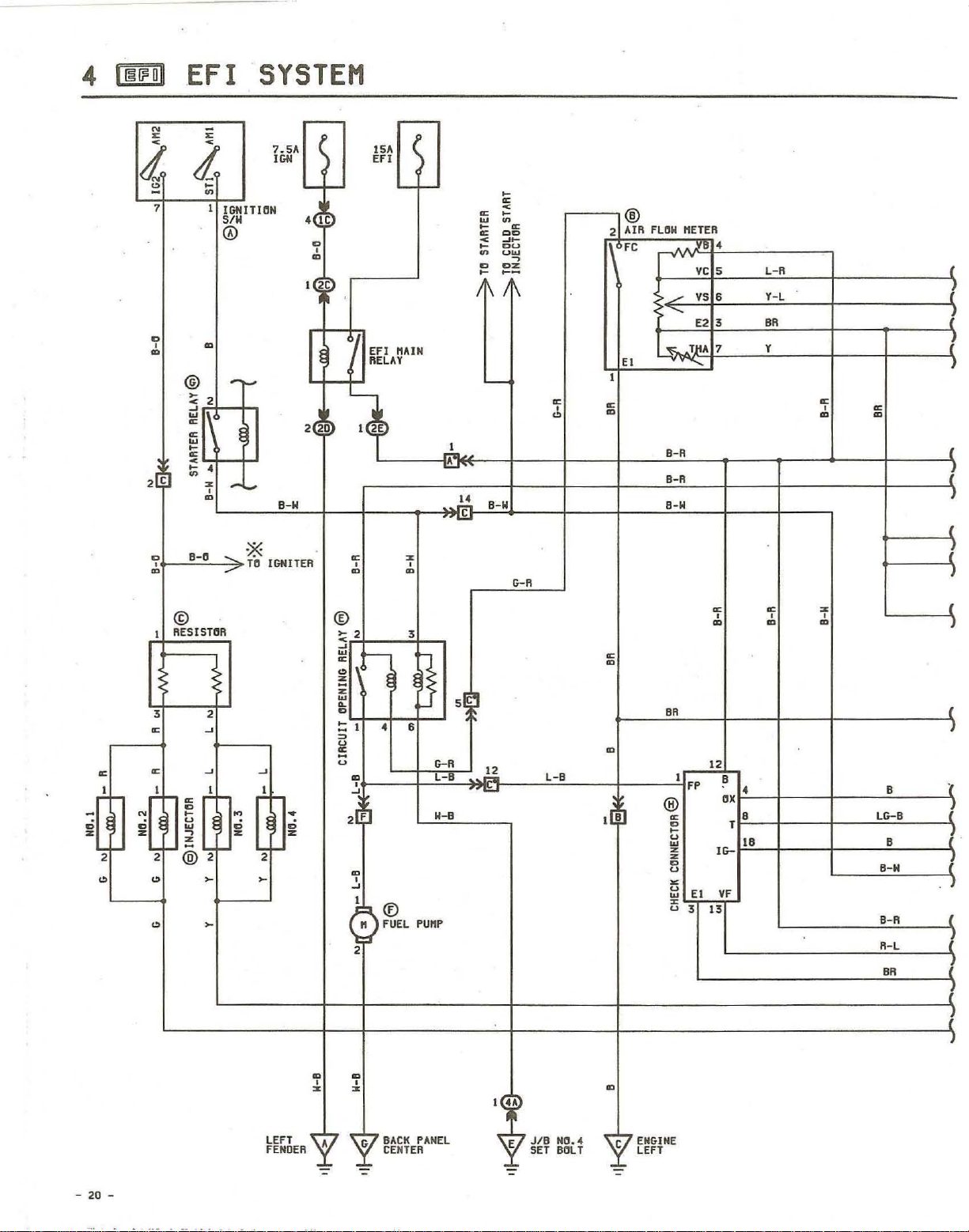
4 I I§II'
ull
.
EF
I
SYSTEM
N
< <
"
rt
'"
-
7 I
i'
i
~
~
IGNITION
S/W
®
D
,
m
2[C
D
,
m m m
I
3
~
~
I
D
Z
2
'"
~
'r
N
ci
Z
2
'"
'"
m
@
--
~
2 <
~
w
~
~
w
~
~
<
~
~
•
,
'"
--
m
9-0
© ®
RESISTOR
~
D
~
U
,
'"
@
"
TO
...-
---
*
2
~
~ ~
I I
~
ci
Z Z
2 2
~ ~
~
r-
7.5"
I
GIl
'-
•
2
B-W
IGNITER
•
ci
I
D
,
m
r
,
IC
2C
20
~
~
<
~
w
~
'"
Z
"
w
~
D
!:
~
U
~
U
2[F
'"
m
~
m
~
-
15A
EFI
-
EFI
"AIN
RELAY
I
2E
, ,
2
I
,
,
I
2
f---1
"
!
•
®
FUEL
'"
<}
r-
3
I-
l-
6
PU"P
~
I>-R
l-B
W-B
.J..
,L.
~ ~
w
~
~
<
~
~
D
~
I \ I
.~
. .£.
5~
~
.M-
. .£.
-
B-W
~
~
<
~
OD
~~
DU
uw
DZ
~-
~
,
1\
I>-R
~
,
'"
l-B
®
AIR
2
FC
EI
I
~
m
~
m
m
I(BJ
FLOW
...-
"-
'&
9-R
9-R
B-W
BR
®
~
D
~
U
Z
'"
Z
D
U
~
U
'"
U
"
"ETER
VC
VS
E2
T1'A
I
FP
EI
3
12
13
~
m
•
5
6
3
7
,
II>-
VF
B
ox
•
•
T
IB
l-R
Y-l
9R
Y
~
, ,
m m
~
,
m m
'"
~
(
/
e
/
B
ll>-9
B
B-W
B-R
R-l
BR
m
m
,
,
'"
'"
LEFT
FENDER
-
20
-
•
G
BACK
CENTER
PANEL
I
••
JIB
SET
NO."
BOLT
E
m
C
ENGINE
LEFT
~
~'
~.
.L
.t...
e
J...
~'
L-R
Y-L
8R
Y
5
ve
4
VS
12 E21
3
THA
®Eeu
15A
STOP
18
,--
-
8
4
)
r-
IH
%
,
~
38
BATT 2
\-
______
\-
___________
~
_ _
~"~R_=-~I~~~=f2~
8R
(~_~8~R~
I
~~------~~2~~~:Ji'
"
8
\-
______ ~ __________
~~~7~~---~8~-~R~----~1
~
__ · ________
R>,
WATER
\V
GD
~~
®
<Do.
®
THER"O
SENSftR
L J
~~~?tI~~
'~~~~~
Y<o.---
_'-VT"A
~
L----=~
~~U!~~
SENSOR
T-VIS
CO~V
L'
VSV
+_I
---"~-~R~--"l"
_____
SENSOR
L~3~
f-2
___
vee
I
~--
------
r--e---i
_T--+---=8~-~"----~3
G~
__
__
~L~
__
-"RC-_--=1
L-R
~~'--~
---'""---
--~1~8
SEALED
B
,-
-t
LG-8
*81
+8
~I~O
THW
14 E2
~6
IDL
4'
YT
12
vee
v-Ise
B
13
OX
I
7 T
STA
A
QDEeu
"".
,--::c
.-~
Ale
I',
,,S,---,,,"
G+~3~ir::~~~B=:=:~~I~(,~~----1
G-F·~I~:=~"~==:=jl-~~2~~~~
I
IGF~S
~t
I I R
NE~_+
IGTl"B'---1Ir---::cB ___
r ! {
G-
~
il
~~--~B~-Y~------~O~
------~--------~~o
i =
I B 8
I Q
R-"
-="'--
il';';'I~'~·
.
--=",-
__
-<:::--
I
{ R-L
~
==========~2
~~~~'~==t==i
==~R~
2VF
"~
===!j6
51TH
I
I
wi
;1
:;:1
:o!1
!!!I
•.
\-
\-
_ _
~--------_r-+--Y~--~4
__
-t
_______
r-
________
_
-+_+-_~G
-+
__
+---=B~R
___
____
~9
~S
<DEeu
_10
-20
EDI
__
--=
G-'--'"'-__
FROM
@
CHECK
ENGINE
'::.f'1C\l't.!,ID,,---=R,,-.oL--<E-FR"f1
Ale
AttPl I FlEA
_I
~
IID-I-ST-R-I-8U-
~
~
_
"'@2
~
T
-O~R
IGNITER
.,
,
m
FUSE
GAUGE
AIR
INTAKE
CHAMBER
r-
-----;--~--=B~R----~
r-
__
~-t-~B~R~_,7
~
H 8 L
ID~ED2
EI
I I
__________
i
I
I
S IH
-
21
-
 Loading...