

.
.....
TOYOTA
ELECTRICAL WIRING:
, .
.)
..••
(.:J:
~"G
tIll'"
>
FOREWORD
This wiring diagram has been prepared
electrical system
of
the 1982 TOYOTA CeUCA SUPRA,
to
provide information on the
MA61L
series.
All
information
at
the time of publication. However, specifications and procedures are
subject to change without notice.
in
the manual
is
based
on
the latest product information
TOYOTA
MOfOR
SALES
CO.LTD.
@
1981
TOYOTA
All
rights reserved. This book may not be
produced or copied,
the written permission
MOTOR
in
SALES
whol. or
of
Toyota Motor Sales Co"
in
Ltd.
CO.,
part,.
LTD.
r.·
without
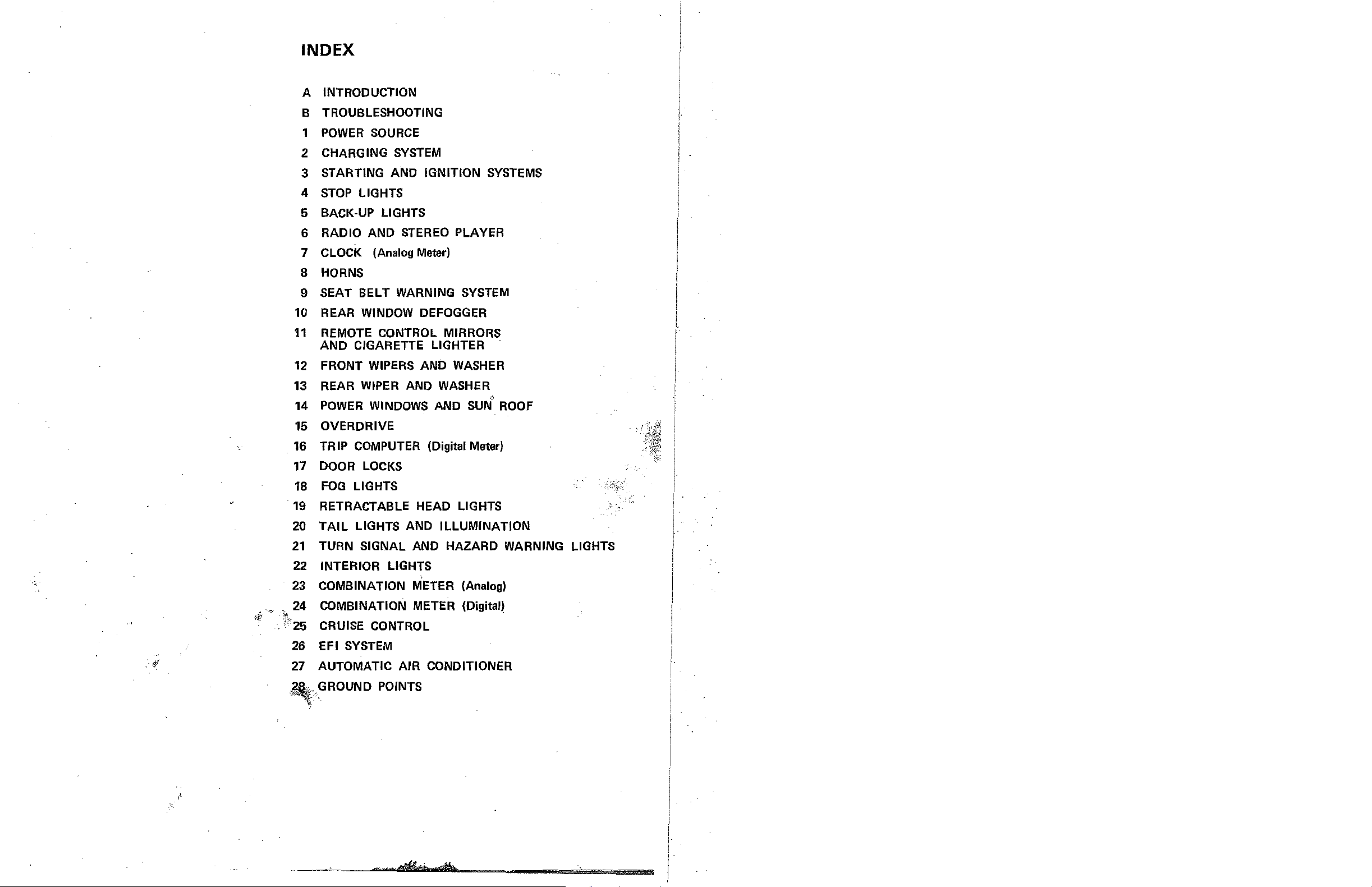
INDEX
INTRODUCTION
A
B TROUBLESHOOTING
POWER
1
2 CHARGING
STARTING AND IGNITION
3
4
STOP
BACK-UP LIGHTS
5
RADIO AND
6
CLOCK (Analog Meter)
7
SOURCE
SYSTEM
LIGHTS
STEREO
8 HORNS
SEAT BELT WARNING
9
10 REAR
11
REMOTE CONTROL MIRRORS
AND CIGARETTE LIGHTER
12 FRONT
REAR
13
14
POWER
15
OVERDRIVE
TRIP
16
WINDOW
WIPERS
WIPER
WINDOWS
COMPUTER
AND WASHER
DEFOGGER
AND
AND
(Digital Meter)
SYSTEMS
PLAYER
SYSTEM
WASHER
b
SUN
ROOF
17
DOOR
18
FOG
19
RETRACTABLE HEAD LIGHTS
20
TAIL
21
TURN SIGNAL AND HAZARD WARNING LIGHTS
INTERIOR LIGHTS
22
',.'
.'.
ity
·f
23
COMBINATION METER (Analog)
24 COMBINATION METER (Digital)
",.-
',*.
..
1<'25
CRUISE CONTROL
26
EFI
27 AUTOMATIC
,;GROUND
LOCKS
LIGHTS
LIGHTS AND ILLUMINATION
,
SYSTEM
AIR
CONDITIONER
POINTS
"'
G'F7'

A II\lTRODUCTION
As shown
in
the index, the entire electrical system
is
source and ground points.
The power source illustrations show how battery power
the
the system
Most
systems are drawn from the fuses
Joining the power source with any system will
Location of the ground points are shown as well
fuses protect.
in
junction blocks (JIB)
~esuit
in
as
how
other.
is
Each system
the
On
left
displayed on two facing pages for easy reference.
is
shown
the
system circuit and connectors as much as possible as they are actually posi-
tioned in the vehicle.
is
The system wiring routing and connector location
displayed on the right.
composed of 28 systems, including
is
distributed
No.2
to
each fuse and what loads in
and
No.3.
the
the complete system.
the cOmponent grounds'are related to each
power
System Title
'System
Connector
Illustration
Circuit
----,l!Oj
IQI
o
! £}!
_Wiring
Routing
and Connector
Location
II
II
INTRODUCTION
Troubleshooting Hints and Component Operation
For assistance
component can be found boxed within the system circuit.
in
understanding
the
system and help
in
repair, voltage, resistance
or
operation
of
each
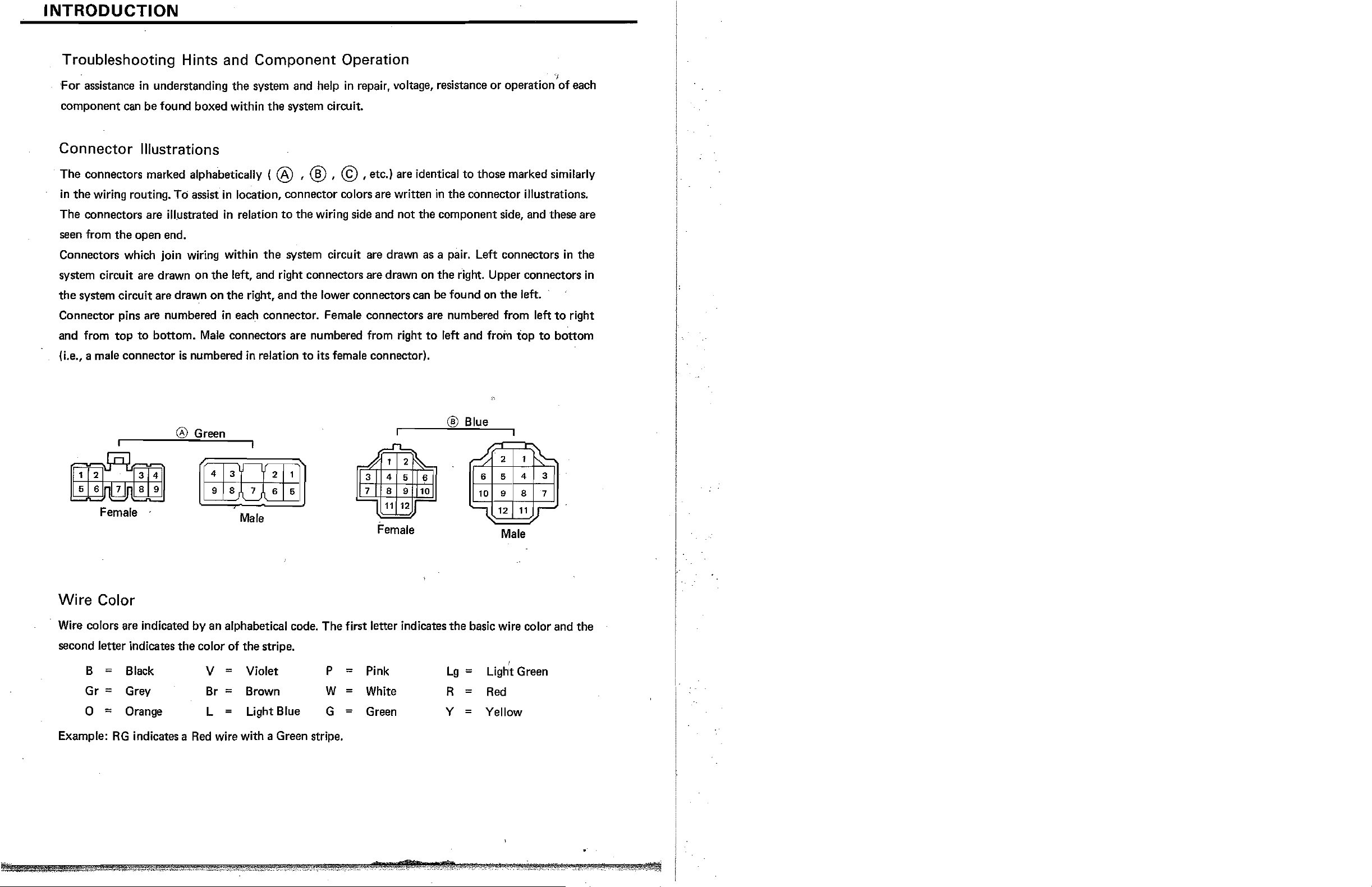
Connector Illustrations
The connectors marked alphabetically ( ® ' ® ' ©
in
the wiring routing.
The connectors are
seen from the open end.
Connectors which join wiring within
system circuit are drawn on the left, and right connectors are drawn on the right. Upper connectors
the
system circuit are drawn on the right, and
Connector pins are numbered
and from top
(i.e., a male connector
to
To
illJ,Jstrated
bottom.
is
assist
in
location, connector colors are written
in
in
each connector. Female connectors are numbered from left
Male
connectors are numbered from right
numbered
relation
the
in
relation
to
the wiring side and not the component side, and these are
system circuit are drawn as a pair. Left connectors
the
lower connectors can
to
its female connector).
,etc.)
are identical
in
the connector illustrations.
be
found on
to
left and from
to
those marked similarly
the
left.
to
top
to
bottom
in
right
the
in
® Blue
® Green
.11..
1
1 2
4
8
11
:;,...
6 6
9 10
12
-
Lg;
=
Y =
.#
31
8 9
Female .
Wire
Wire
second letter indicates
Example:
Color
colors are indicated by an alphabetical code. The first letter indicates the basic wire color and the
the
;
B
Gr
0
=
=
RG
Black
Grey
Orange
indicates a
9 8 7 6 5
Wfu1ili
Male
color
of
the stripe.
=
V
Br
L
Red
Violet
Brown
=
=
Light Blue
wire with a Green stripe.
P
W
G
I
7 I
1
Female
=
Pink
=
White R
=
Green
2
~
5 4
6
10
9 8
12
I
Male
,
Light Green
Red
Yellow
11
~
3
7
r
B TROUBLESHOOTING
Troubleshooting Procedure
1.
Determine what
is
wrong with the system.
2. First read the diagram
the
within
3. Locate
a. Determine whether
individual circuit.
Check
If they are normal,
Refer
(NOTE: Each component
If the related systems are normal, the common circuit (power source or ground points)
The problem lies within
b. Locate
lamp.
->,.,:,'/'"
4. Repair and re-check
If any wiring was disconnected for troubleshooting, re-connect it and check
system circu it.
the
cause of
other
loads
to
the
POWER
the
exact point
so
you understand the system. Refer
the
problem.
the
problem
or
switches which are
the
problem lies within
SOURCE
is
grounded at 2
the
indiVjdual system.
of
the problem by narrowing down the
the
circuit.
to
the
is
with the common circuit (power source
in
parallel with
the
particular system itself.
or
GROUND POINTS and check
or
3 points.)
the
problem component.
component operation boxed
or
ground)
the
related systems.
is
okay.
flrea
with a voltmeter
the
related circuits.
or
test
or
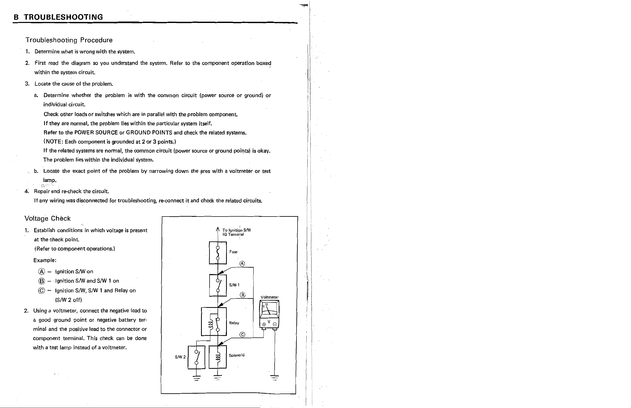
Voltage Check
1.
Establish conditions
at
the check point.
IRefer
Example:
to
component operations.)
® - Ignition
® - Ignition
© - IgnitionSIW,
(SIW
2
2. Using a voltmeter, ·connect the negative lead
a good ground point
minal and
component terminal. This check can be done
with a test lamp instead
the
positive lead
SIW
SIW
off)
in
which voltage
on
and
SIW
1 on
SIW
1 and Relay on
or
negative battery ter-
to
the connector
of
a voltmeter.
is
present
to
or
To
Ignitio;o
IG
Terminal
8/W
!
fuse
®
81W
1
®
Relay
Voltmeter
0"
©
~'[11
'--+-
.....
Solenoid
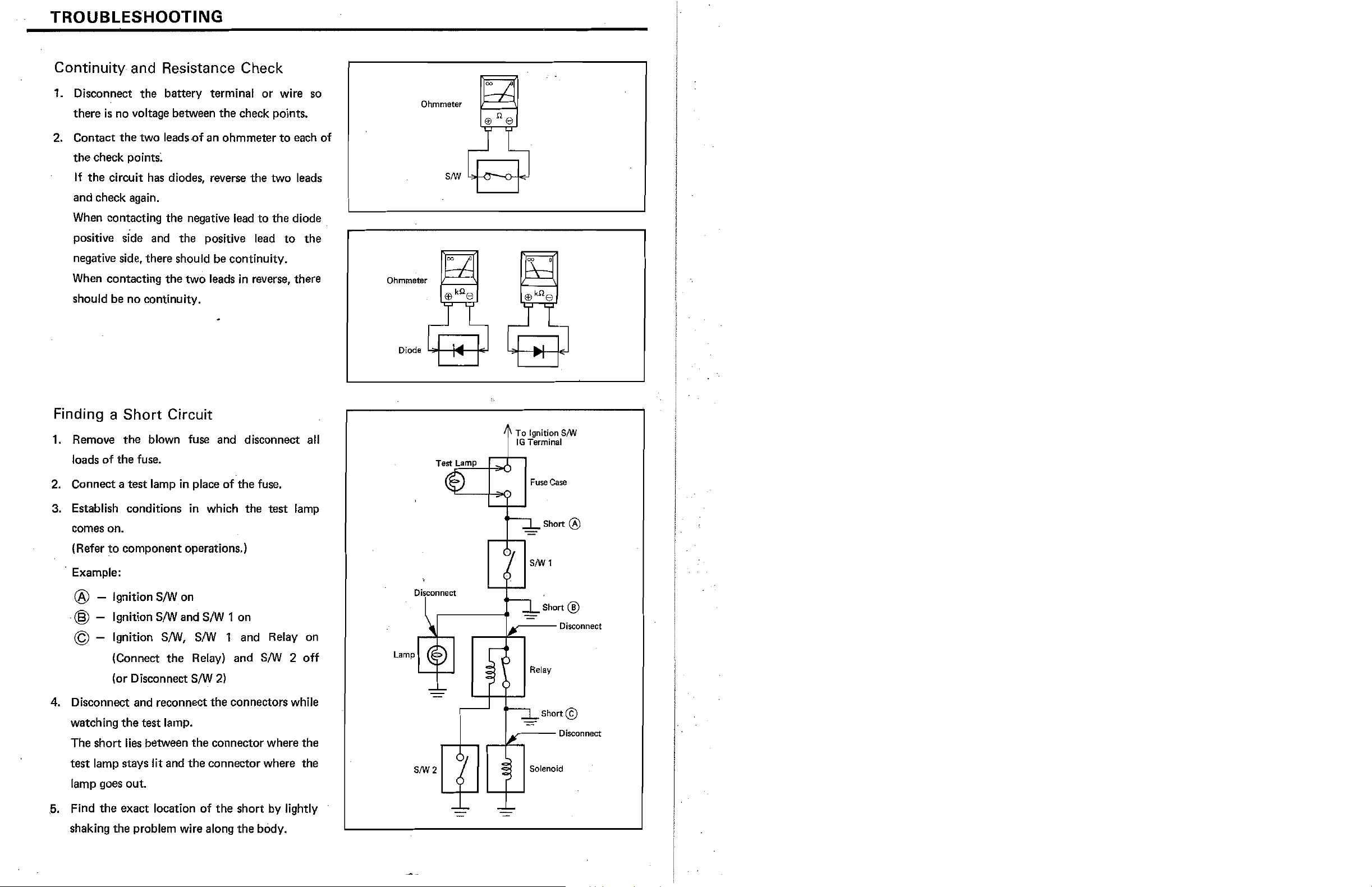
TROUBLESHOOTING
Continuity and Resistance Check
1.
Disconnect the battery terminal or wire
there
is
no voltage between the check points.
the
2. Contact
the check points;
If the circuit has diodes, reverse the two leads
and check again.
When
positive side and the positive
negative side, there should be continuity.
two leads{)f an ohmmeter
contacting
the
negative lead
to
lead
to
the
each of
diode
to
the
so
Ohmmeter
When
contacting the two leads
in
reverse, there
should be no continuity.
Finding a
1.
Remove
loads
2.
Connect a test lamp in place of the fuse.
of
Short
the
the
Circuit
blown fuse and disconnect
fuse.
all
3. Establish conditions in which the test lamp
comes on.
to
(Refer
component operations.)
. Example:
® - Ignition S/Won
@ - Ignition
© - Ignition
S/W
and S/W 1 on
S/W,
s/W 1 and Relay on
Ohmmeter
Disconnect
4 To
:
fG
---
19oition
Terminal
Fuse
Case
Short ®
S/W
1
Short ®
SIW
Disconnect
the
(Connect
(or Disconnect
4.
DiSC{)nnect
watching
The short
and reconnect
the
lies
test lamp stays lit and
test lamp.
between the connector where the
Relay) and
S/W
2)
the
connectors while
the
connector where the
lamp goes out .
. 5. Find
exact location
of
the short by lightly
the
shaking the problem wire along the body.
S/W
2 off
SIW2
Relay
-
_--
Solenoid
Short@)
Disconnect
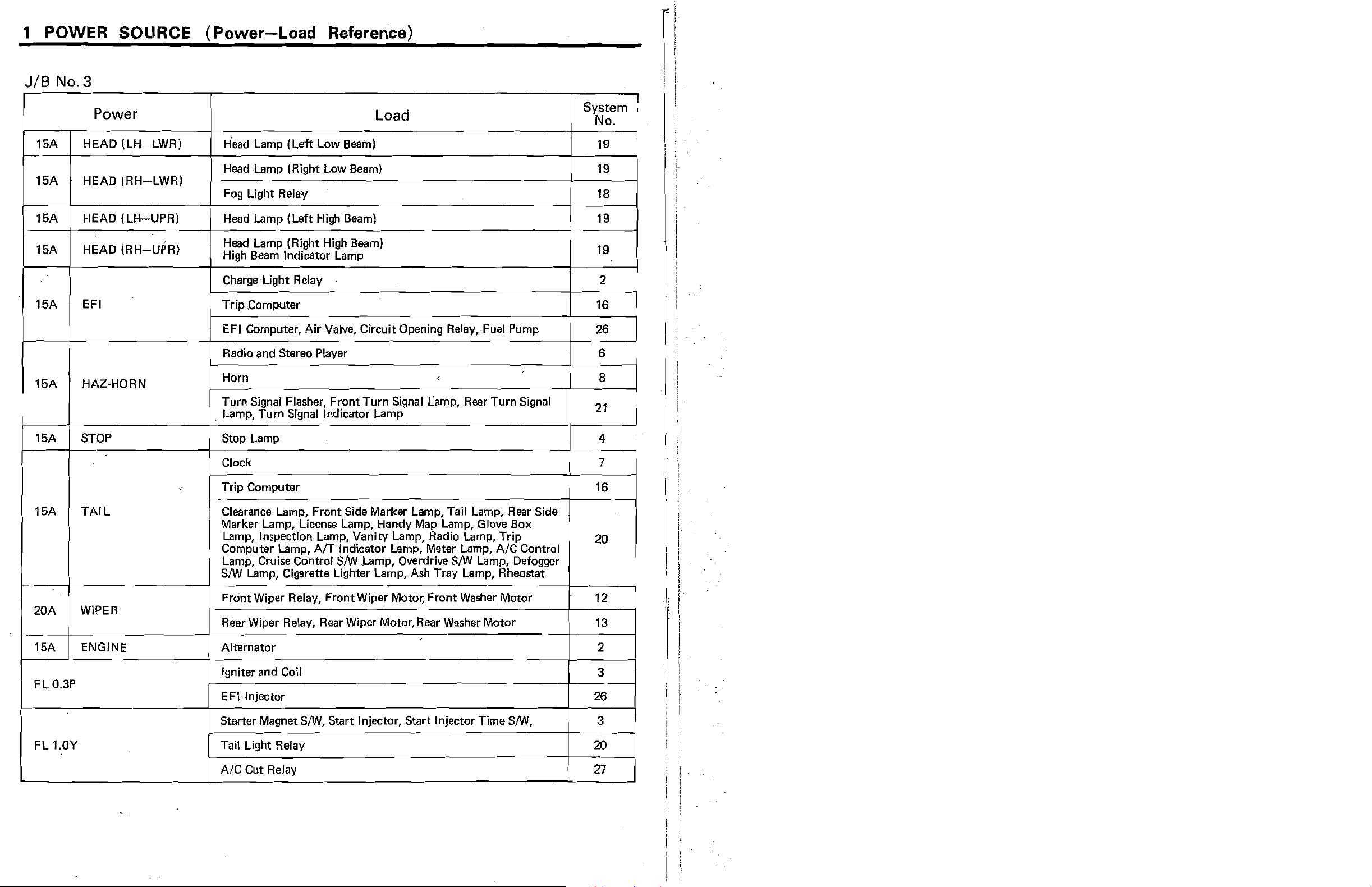
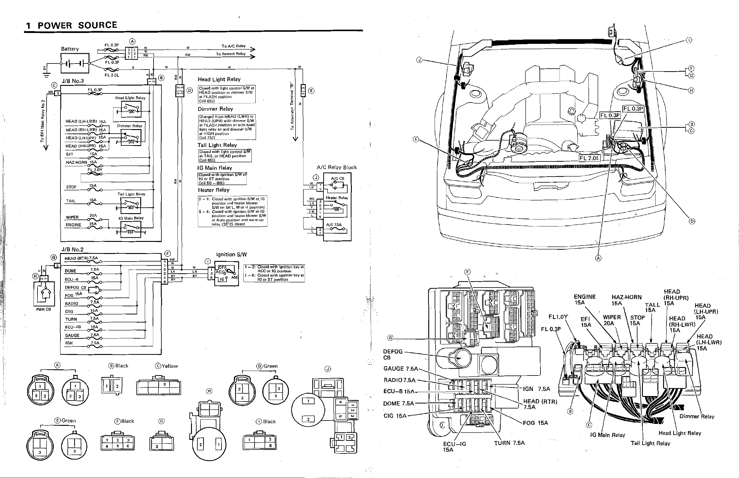
1 POWER SOLIRCE
JIB
No.3
(Power-Load
Reference)
[
I
15A
16A HEAD
16A
16A
16A EFI Trip ,Computer
1M
,
16A STOP
Power
HEAD
,
HEAD
HEAD
HAZ-HORN
(LH-LWRj
(RH-LWR)
lLH-UPR)
(RH-UPR)
J
Head Lamp (Left Low Beam)
Head Lamp (Right Low Beam)
I
i Fog Light Relay
I
Head Lamp (Left
Head Lamp (Right
High
Beam .Indicator Lamp
Charge Light Relay
,
EFI Computer, Air Valve, Circuit Opening RelaY,Fuel Pump
,
Radio and Stereo Player
i
Horn
!
!
Turn Signal Flasher,
i . Lamp, Turn Signal Indicator Lamp
i
Stop Lamp
High
High
Front
Beam)
Beam)
Turn
Load
.
<
Signal Lamp, Rear
Turn
Signal
System
J
i
I
i 4
No.
19
19
18
19
19
2
16
26
6
8
21
i
!
,
I
I
i
16A
20A WIPER
TAIL Clearance Lamp,
,
.
_.
1M
FLO.3P
FL 1.0Y
ENGINE
Clock
"
Trip Computer
Front
Side Marker Lamp, Tail Lamp, Rear Side
Map
Marker Lamp, License Lamp, Handy
Lamp, Inspection Lamp, Vanity Lamp, Radio Lamp, Trip
Computer Lamp,
i
Lamp, Cruise Control
S/W
i
i
!
Lamp, Cigarette Lighter Lamp, Ash Tray Lamp, Rheostat
Front
Wiper Relay, Front Wiper Motor.
Rear Wiper Relay, Rear Wiper Motor, Rear Washer Motor
AfT
Indicator Lamp, Meter Lamp, AIC Control
S/W
Lamp, Overdrive
Lamp, Glove Box
S/W
Lamp, Defogger
Front
Washer Motor
.
Alternator
Igniter
EFllnjector
Starter Magnet S/W,
and
Coil
Start
Injector,
Start
Injector Time S/W,
7
16
20
12
13
!
..
i
2
3
26
3
!
I
!
)
I
Tail Light Relay
AIC
Cut
Relay 27
20
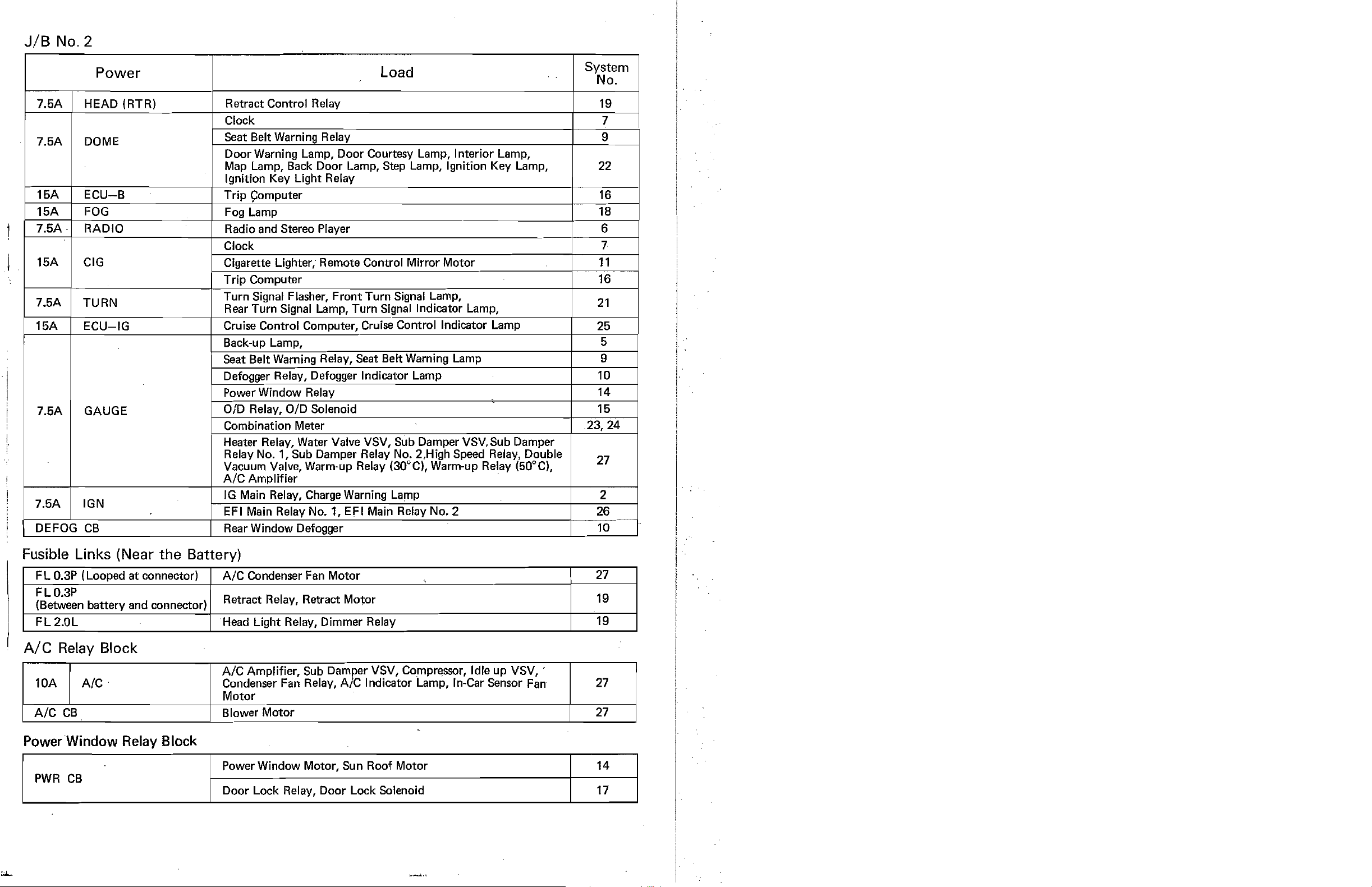
JIB
No.2
Power
7.5A HEAD (RTR) Retract Control Relay 19
Clock 7
7.5A
,
1
15A
.
7.5A
15A
7.5A GAUGE
7.5A
DEFOG
DOME
CU-B
OG
RADIO Radio and Stereo Player
CIG
TURN
ECU-IG
IGN
CB
Seat Belt Warning Relay
I
Door Warning Lamp, Door Courtesy Lamp, Interior Lamp,
Map Lamp, Back Door Lamp, Step Lamp, Ignition Key Lamp,
Ignition Key Light Relay
Trip
~omputer
........................
Fog Lamp 18
Clock
Cigarette Lighter, Remote Control Mirror Motor
Trip Computer
Turn Signal Flasher, Front Turn Signal Lamp,
Rear Turn Signal Lamp, Turn Signal Indicator Lamp,
Cruise Control Computer, Cruise Control Indicator Lamp
Back-up Lamp, 5
Seat Belt Warning Relay, Seat Belt Warning Lamp
Defogger Relay, Defogger Indicator Lamp 10
Power Window Relay
OlD
Relay,
Combination Meter
Heater Relay, Water Valve VSV, Sub Damper VSV.Sub Damper
Relay
Vacuum Valve, Warm-up Relay (30
A/C
Amplifier
IG
Main
El'l
Main
Rear Window Defogger
OlD
Solenoid
No.1,
Sub Damper Relay No. 2.High Speed Relay, Double
Relay, Charge Warning Lamp 2
Relay
No.1,
EF
Load
G
C), Warm-up Relay (50" Cl.
I Main Relay
No.2
t=1t=}
System
NQ.
~
...•.....
21
25
15
.23,24
27
9
22
16
6
7
11
16
9
14
-
Fusible Links (Near the Battery)
F L O.3P (Looped
FLO.3P
(Between battery and connector)
FL
2.0L
Ale
Relay Block
lOA
A/C
A/C
CB
PowerWindow Relay Block
PWR
CB
at
connector)
.
A/C
,
Retract Relay, Retract Motor
Head Light Relay, Dimmer Relay
A/C
Condenser Fan Relay,
Motor
Blower Motor
Power Window Motor, Sun Roof Motor 14
Door Lock Relay, Door Lock Solenoid
I
Condenser Fan Motor
Amplifier, Sub Damper VSV, Compressor, Idle up VSV,
A/C
Indicator Lamp, In-Car Sensor Fan 27
,
27
19
19
27
I
17
, POWER SOURCE
,
r
Battery
© JIB No.3
FL
!LH-lWR.
O.3f'
15A
15A
N
0
z
;:-
..
0
'"
~
;;:
'"
{2
wira
HEAD
HEAD (RH.LWRr1$A l
HEAD (LH·UPRi
,if HEAD {RH-UPR) 15A 1
EFI
HAZ·HORN 15A
ISA
fL
LOY
I
STOI'
TAIL
WIPER
ENGINE
'SA
1SA
20A
,s):""'"
FL03?
®
rw
Head
Ught
c-:i-o~1
3 I
~
~
Relay
'I
w
I"
DImmer Relay
:vI
,
Tru!
Ught
Relay
1-o~1
, I
10
l
Main Relay
1-
.1
rr I
~
RW
.
w
To Retract
Head
Light
Closed with light contrOl 8/W
HEAD
position
<It
.FLASH pos.ition :
~i?"~.
___
Dimmer
:changed
i HEAD {UPR)
at
light
it
~1!2~_
~
Tail
CIOSl)d
at
Coil65H
IG
Closed
IG
COU
Heater
j5 -4:
I position
, S/W
i5
I
Relay
from HEAD
FLASH position
r-elay
on
HIGH positiQr;
..
Light
with
TAl
L
or
HEAD
Main
Relay
with
Ignition
orST~ltion
50
-BOil
Relay
Closed
on
4:
Closed
po~ition
at Auto
relay (30"CJ
ToNCRelay
Relay
Relay
or
dimmer
.. , ___
(LWRI
with
dimmer
or
with head
and
dimmer
_____
Relay
Ught
control
position
S/Wat'
~-~c=--~
with
ignition S/W at,lG '
and
heater blower
{at
L, M
with
iglJition sIW
and'
he.ater blower
~sition
cI¢~d
...
at
I
srw
I
;
to
'
S{W
S/W
--'
SIW"I
:
or
H positionl
at
and warm-up
lG
$/'oV
!
l
LA
wa
Ln
y
LW
L
,
Q)
Ale
Relay
AleCB
NC10A
Block
-----
_______________
-----1
--------0
\
\ ©
F
G
®
@
:
i
; I
~!
~
',1
'I
·1,
d
'Ii
.
\:
,
JIB
No.2
,.::.:.::...:.==-----------. ® Ignition
@
~GIf~H~E~A~D=(RT==R):7~.5~As:~~r=~~======r~fERlw~
> •
[
~
®
N~I
'
l9
PWfl
~00M~""E_-o;.1,,5A_'>_-....
::ii
I.,
CB
~E""CU'!c-6~_<:i_:;:.:..o_--l
DEFOG
FOG
RADIO
elG
TURN
ECU-lG
GAUGE
taN
CB-t
lSA
.5A
_11>----'
"'--'iV
1.SA
,SA
7.5A
15A
1.SA
7.SA
"'""'-'"
@Black
..... ~ I;
r-;:::::I-'!-~
,
I
I
©Yellow
5
I.R
2
~I
~~~~~'~'E=il
r
(D
Ll'I
SY
~----,
1
IACr::~
~JLJMI~-§.
~
I-.
.....
~
®
SIW
ACGcr
'~';
~'
AM
3,
1 -
6:
,IG.rST"",'6oo
IG
CI""d
with
Closoo
with ignition key at
@Green
position
'gnition
"Y'::I'
F,L
DEFOG
CB
GAUGE
RADIO
----+4-:=.~~t~~J;;;;J
7.~r'
__
'
7.5A
-Ftf~~ff:nITn~:~::~
ECU-B 7.5A
__
'
'~r'~
DOME
7.5A--;'~:-7"1t
IRTR)
ENGINE
15A
-
HAZ-HORN
15A
..
CIG
®Gr
••
n
®Slack
'(DSlack
15A
FOG
15A
HEAD
HEAD
(LH·UPR)
ECU-IG
15A
TURN
7.5A
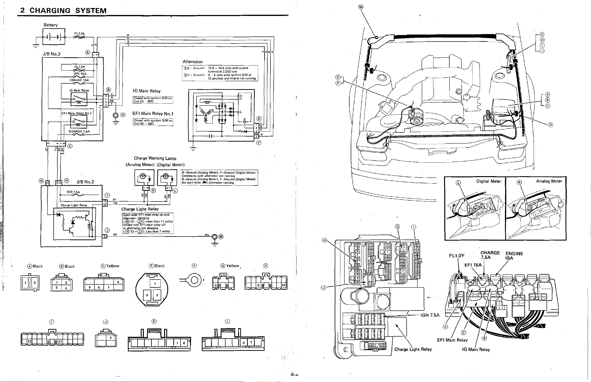
2 CHARGING
Battery
JIB
No.3
SYSTEM
FL1.0Y
EF'15A
ENGINE
15A
.,
Alternator
~
@3-Ground:
i @1 - Ground: 0 - 4 volts with ignition S/W
-----------.---
13.8 -
14A
funning
at
tG
position
vojt~
with
2,000
r:pm
"'lid
engine
~nqine
at
not
runnIng
il
il
II
l
@
r~
r"
10 Main ReillY
CHAAGE7,5A
~
® JIB No.2
IGN
7.SA
Charge
light
ReillY
®
CD
17
E.
IG
Main Relay
EFI Main Relay No.1
: Closed with ignition
'Coil 50 -
a~L
___
Charge Warning Lamp
(Analog Meter) (Digital Meter)
BY
yw
Charge Light Relay
lopen
with
EFI
main
EFI
..
relay on and
moTf!
than
main relay
leu
than
al~nator
(@
,CIOi»d
I
'Of
altemator nOt charging
:(@13
w.
s;,Qarging
13~(d)2:
with
Q)2:
$,.w'Q'nl
11
voltst
6ft
7voltsl
.
..J
~--------------~®
·l8-GfOU~d-(·AnaIOg
Continuity with ahematrJr
a-Ground
~~
ctmtirrutty.h
"
Mew).
7-Ground
{Analog Meter}, 7--Ground {Digital Meterl:
not
alternat(lt rl.lMing !
running
jOig.ita!
Mate<I<1
Analog Meter
®Black
®8lack
©Yellow
®Black
®
@Yello
CHARGE
w
,
®
h==~-IGN
Charge
7.5A
Relay
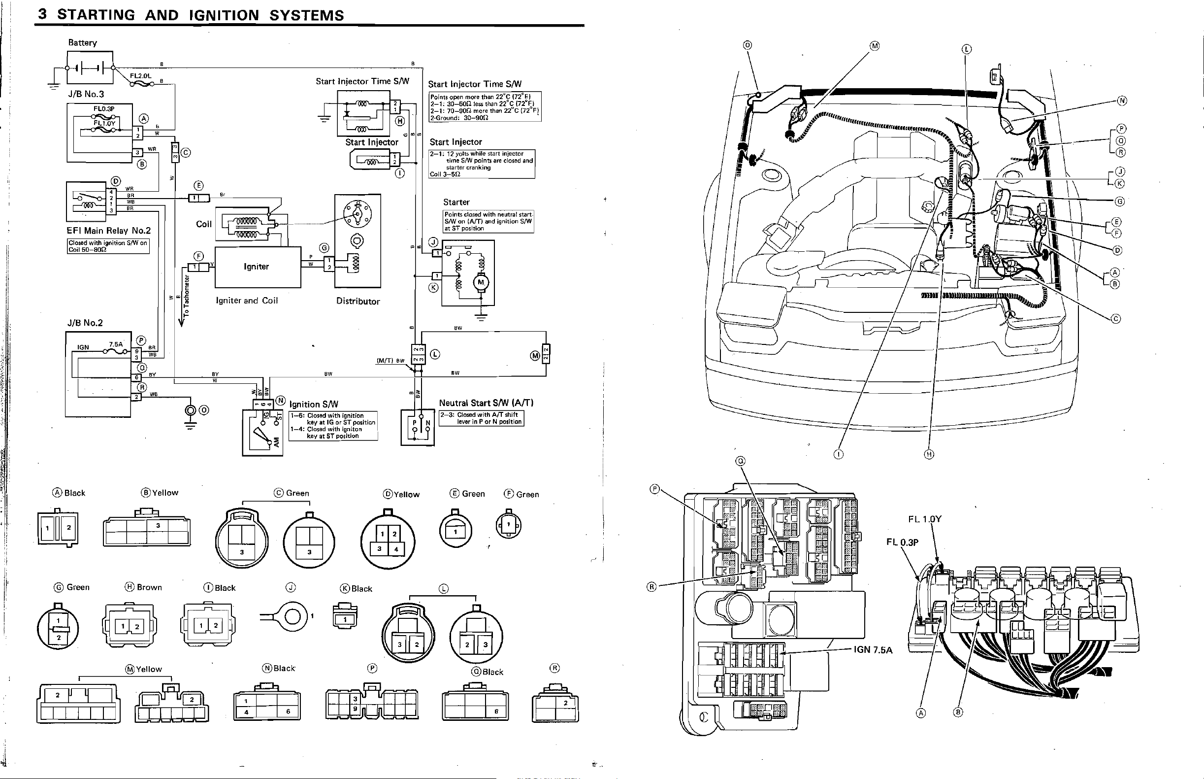
3 STARTING
Battery
JIB No.3
FLO.3P
FLI.OY
I
1-;-1
'-----j~
'------'®
AND
®
,
2 W
IGNITION
SYSTEMS
Start
Injector Time
~:t
L
•
S/W
~
tID
~~~~i
Start
Injector
[
OO~
lj::
(D
Start
Injector Time S/W
po(ot;;l)pen more
2-1:
3Q-5On less than 22"C
2-1:
7tl-S0f2 more than
2-Grotmd;
=,
..
Start
Injector
r2'::':l;""l;iY·0it$-wh~il<~''''''rt'''i!\J'''·
I tim&
I $turter cranking :
'Coll3~Sn
30-900
S!W
poinb
than
22"C
(72
2i"C
''''e",''"'''''-'o
are Closed
"'j
(n"Fj
{n"'n
artd
•
I
'
3
8R
'--_-'I--'
EFI Main Relay No.2
I~~
~9nition
JIB No.2
IGN 7.5A·
L
11
___
S/W on I
~.,
...."._i~~n~a~:u:_-t==='Yiy===:;l
r-®
T
W6
Igniter
Igniter
and
Coil
~-------------------~~----------
~
~
O_@JI!:?Lt.l-6:ClOSedWith.ignitiOn,
._~.~.
® Ignition S/W
~
0 0 key
1Sr
1-4:
~
at
CIO$ed
key
at
Distributor
IG or
ST
position:
with
ignito"
ST position
(M(f)aw
....
Starter
Points
8m
at
• 6W
~
9
CD
"'
dosed
on
(Am
ST posJtion
6W
with neutral
and ignltron
start~1
SIW
".
ii,
I,
i,
®Black
@ G"",n
®Vellow
@Brown
@Vellow
(DBlaok
©Green
@Black
®Black
@VeUow
®
® Gr""n
@Black
®Green
®
,~
®
..k_-""""i--1GN
Ilrrtjp
FL
7.5A
! '
! '
I
I ,
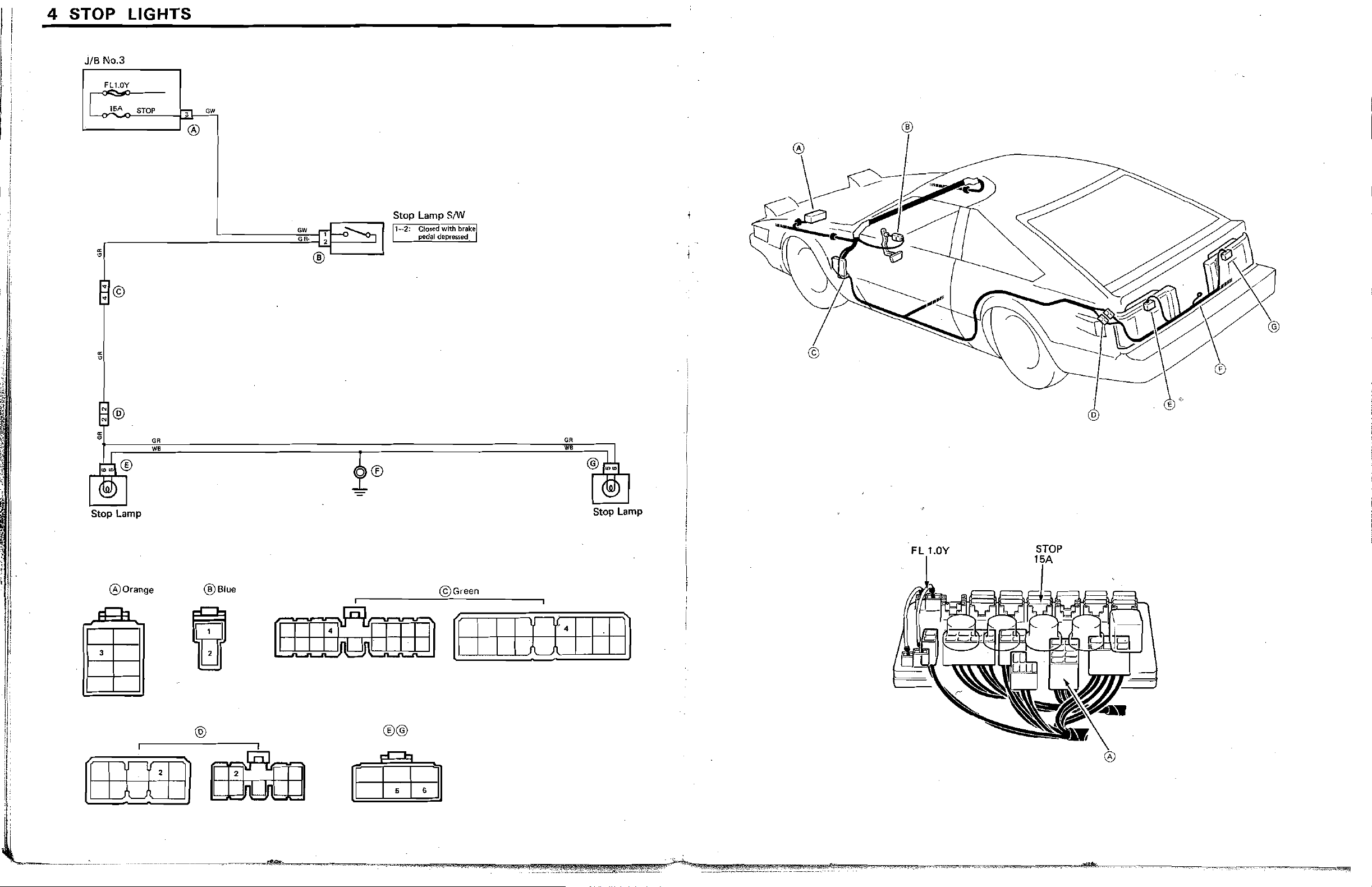
4
STOP
JIB
No.3
fl.l.0Y
l~A
"--
__
LIGHTS
STOP
,
.-J®
ow
®
.--
___
:;1
Stop Lamp
GR
W.
r---
:.:====:=::]~&:~,
:IT!~~
.'
®"-----I
1
®
Stop Lamp
12
: CfOS¢dwlthbrakel'
pedal depressed
SIW
..
. i
o
GR
•
Stop Lamp
®Orange
®Blue
@
[0IIEl
@Gre.n
am:mn
®@
[II
II
[1111
~
FL
1.0Y
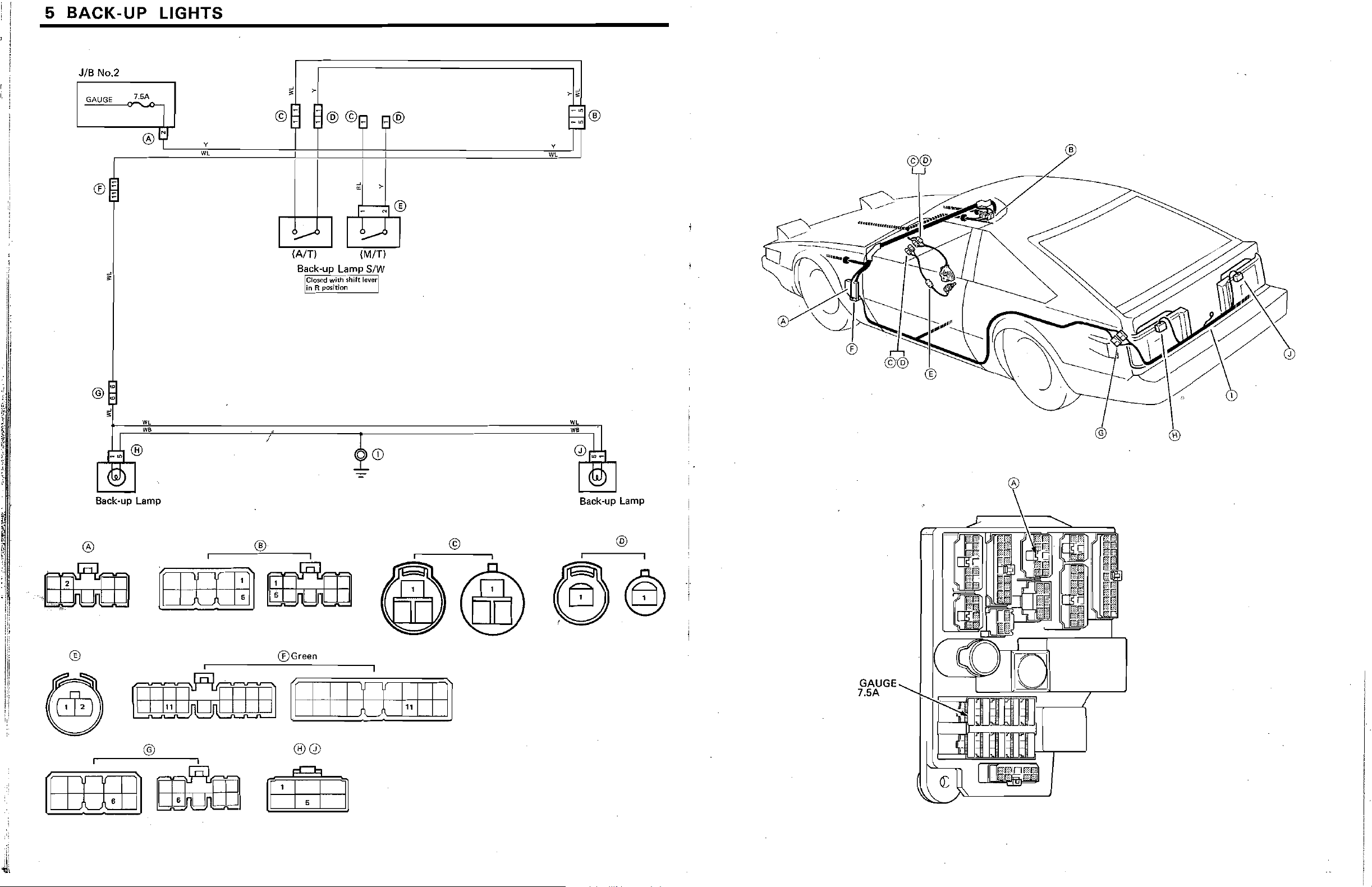
5 BACK-UP LIGHTS
, .
I,
JIB No.2
j
GAUGE
~~
y
'"
(AIT)
Back-up Lamp SIW
ICI{)Sfld with shift
lin
R positlUfl
(MIT)
lawr!
y
WL
~
@:~~====~=====r~==========~~~J)~
,d
~
Sack-up Lamp Back-up Lamp
®
@
®".
mrfiIm
•
®Green
[II
lID
~CD
1
..
11
~
- .
I
t!iIJ
@ ®
I
(EIIIDl
'=:,Id
®0
::::J~J
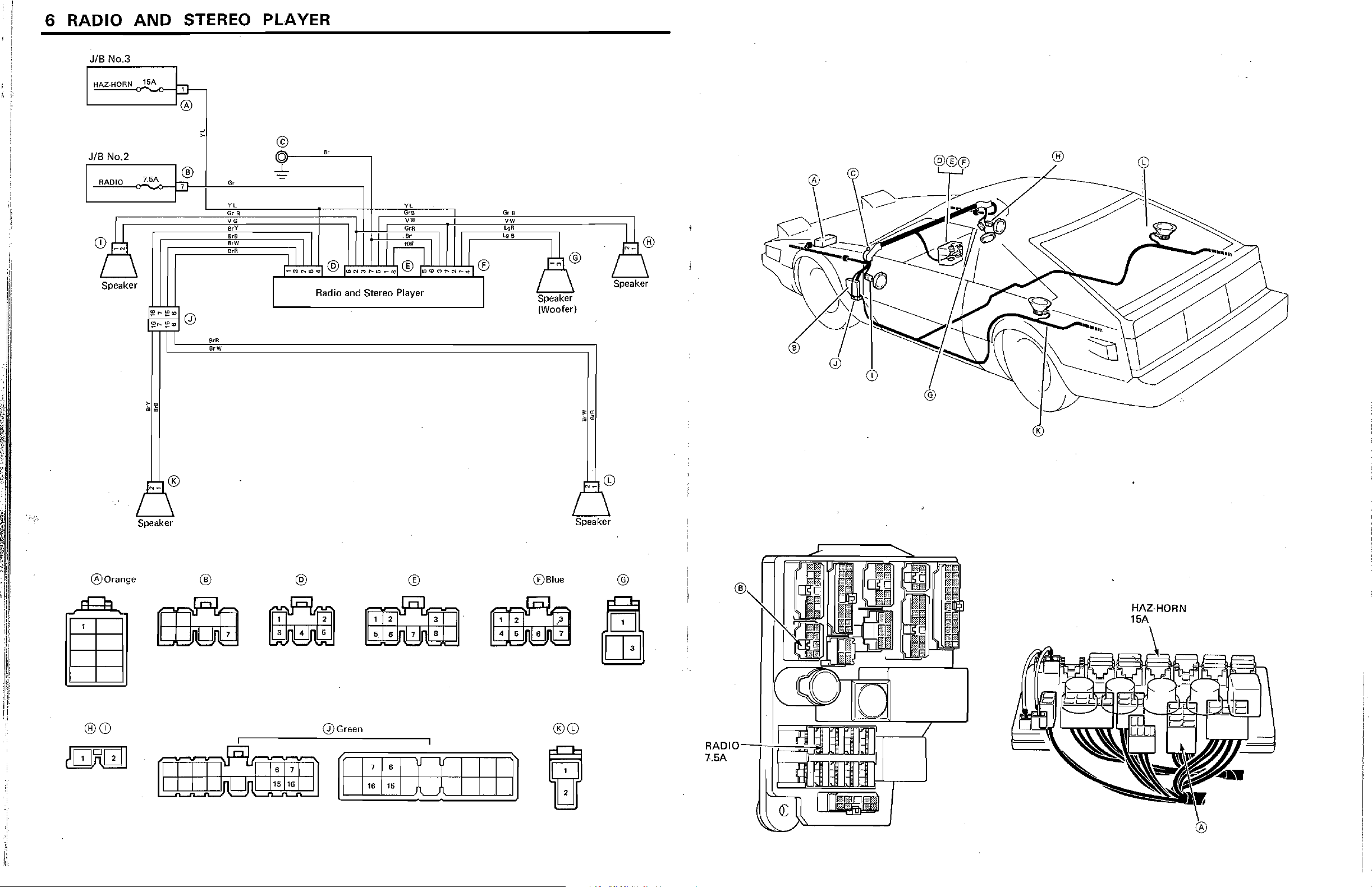
6 RADIO
JIB
NO.3
AND
STEREO PLAYER
HAZ-HORN
JIB
No.2
RADIO
CD~
/ \
Speaker I I \
15A
7.5A
~
~
l'
~
([)
,
"
5,
®
r-'
""
~y~,
G,
fuR
VG
g
~~YC
I:~
,~lN~'@'~N~~._.'®'
Radio and Stereo Player
&B
VW
GrB
V-W
~~
Ie::
..
~~N_J®
f
Speaker
(Woofer)
(~®
-~\@
\
Speaker
@
®
CD
\~
.....
"
•
,
"
([)Orange
®CD
Speaker
® @
Q)Green
®
5,
6 7 8
U
®Blue
4 5 6 7
~
®CD
@
fa
RADIOIIi=~~
7.5A
hh;:::=~
®
HAZ·HORN
15A
7
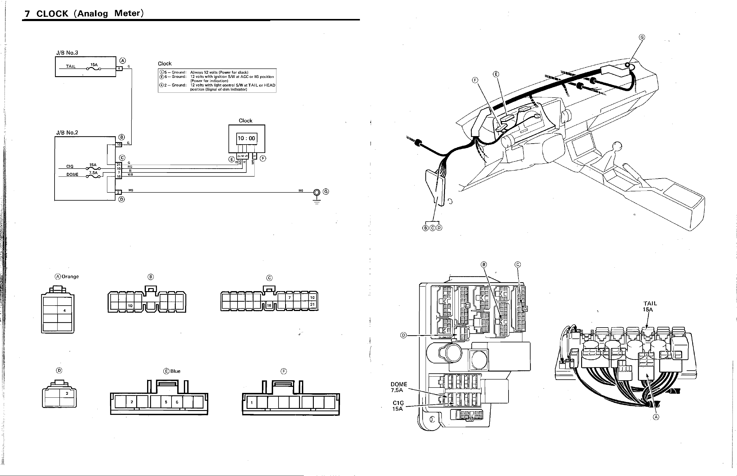
CLOCK
(Analog
JIB
No
3
TAIL
JIB No.2
F:..c..;.;-----,®
lSA
Meter)
o
hit- G
10
G
Clock
®5
- Ground: Always 12 volts (Power for clock)
®6-
Ground: 12 volts with ignition
@2-
Ground: 12 volts with light control S/W at TAIL or HEAD
(Power for indication)
position (Signal
srw
of
dim indicator)
at
ACCot
Clock
IG
@
position
1-----_--......1
00range
~~~2}-W~B~------------------------------------~WB~~O
@
@
®
©
(
TAIL
:'1
@
@Blue
®
I I
i #
DOME
7.5A
I~
 Loading...