

Toyota 2012 CAMRY LE, CAMRY SE, CAMRY XLE, 2012 CAMRY SE, 2012 CAMRY XLE Installation Instructions Manual
TOYOTA CAMRY LE / SE / XLE 2012- DUAL SEAT HEATER KIT
e
N
y
Section I – Pre-Installation Check
Kit Part Number: 250-1897
5
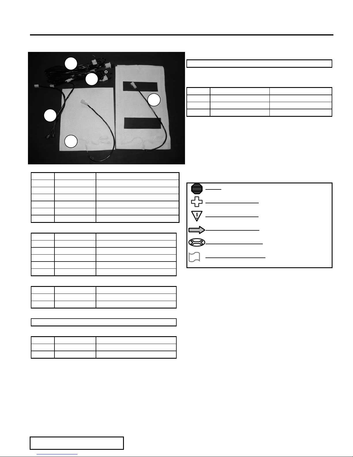
Kit Contents
Item # Quantity Reqd. Description
1 2 Cushion Element
2 2 Back Element
3 1 Driver Main Harness (red)
4 1 Passenger Main Harness (blue)
5 2 Control Switch
6 1 Hardware Bag
Hardwa re Ba g Contents
Item # Quantity Reqd. Description
1 12 Wire Ties
2
3
4
5
3
4
1
2
General Applicability
Camry LE / SE / X LE
Recommended Sequence of Application
Item #Accessor
1Wiring
2 Elements
3
Legend
STOP: Damage to the vehicle may occur. Do not
STOP
proceed until process has been complied with.
OPERATOR SAFETY:
injury
CRITICAL PROCESS:
a quality installation.
GENERAL PROCESS:
processes to ensure a quality installation.
TOOLS & EQUIPMENT:
tools and equipment required for this process
VEHICLE PROTECTION:
of vehicle required for this process
Use caution to avoid risk of
Proceed wi t h caution to ensur e
This highlights specific
This calls out the specific
This calls out for protection
Additional Items Required For Installation
Item # Quantity Reqd. Description
1 Switch Cutout Templat
As needed Vehi cle Protecti on Blanket s
Conflicts
ote: Fact ory leather and cloth
Recommended Tools
Item # Quantity Reqd. Description
Form #5386, Rev. B, 07-11-2014
Page 1 of 8
TOYOTA CAMRY LE / SE / XLE 2012- DUAL SEAT HEATER KIT
Section I I –Ins tallation
Pre-Installation Suggest i o n s
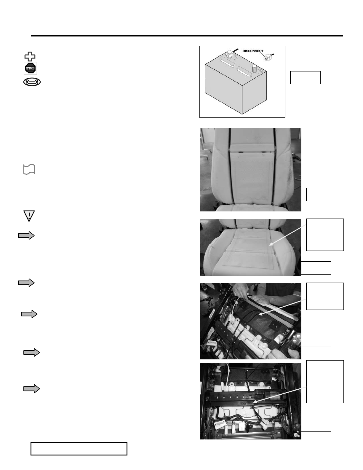
1. Disconnect the negative batt er y cable and wait
for 3 minutes before beginning installation, to
avoid unintended air bag deployment. Note
and record any anti-theft radio codes prior to
disconnecting. Figure 1
2. If vehicle is in Electronics work area,
proceed to step 1 page 4. If vehicle is in
Leather shop, proceed to next section
“Install Heating Elements”.
Install Heating Elements
1. Remove seats from vehicle per vehicle’s
service manual and place on a clean work
surface.
Figure 1
2. Remove seat covers per vehicle’s service
manual.
3. Caution: The heatin g elements must be
installed wrinkle-free.
4. Obtain the back heating element. Remove the
protective layer from the element’s double
sided tape and place it onto the seat back foam
roughly centered on the foam from side to side
with the top of the element just below the
transverse list ing (t ie bar tr ench). Figure 2
5. Route the element wiring harness down to the
bottom of the seat back, inboard of the hinge
cover and under the seat.
6. Repeat the process above for the seat cushion,
laying the heating element transversely such
that it does not interfere with the hor izontal
listings. Figure 3
7. Secure the seat harnesses to the tie down bar
and run down the side listing to the back of
the seat, then down. Re-att ach seat covers.
Figures 4-5
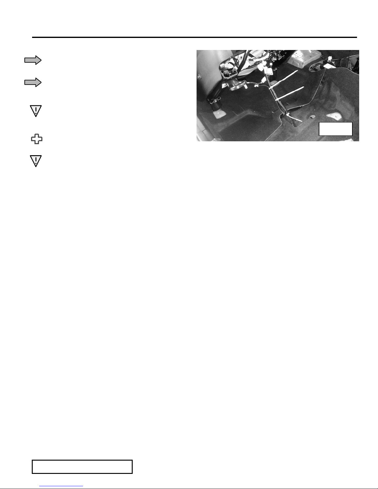
8. Replace the driver and passenger seats into the
vehicle. Connect the seat element connectors
to the main harnesses. Secure the harness
with wire ties and allow adequate slack to
prevent damage during seat adjustment.
Figure 6
Figure 2
Align
channels
with
cutouts
Figure 3
Route
harnesses
here
Figure 4
Twist
harnesses
together
and route
here
Figure 5
Form #5386, Rev. B, 07-11-2014
Page 2 of 8
TOYOTA CAMRY LE / SE / XLE 2012- DUAL SEAT HEATER KIT
Section I I –Ins tallation
Install Heating Elements (cont’d)
9. Make sure vehicle floor-pan is clear and
carefully re-locate seat into vehicle.
10. Ensure all connectors under seat have been
properly connected and secured with wire ties,
and that nothing will be damaged upon seat
movement.
11. Install seat bolts and torque per service
manual.
12. Reconnect battery cable(s). Torque 10mm bolt
to 48 inch-pounds. Re-enter any theft
deterr ent information, if applica ble.
13. Note: If the passenger seat cushion has a Seat
Occupant Sens or fo r Airbag Deployment, it
must be re-calibrated per guidelines in the
Factory Repair Manual.
Figure 6
14. Place the Seat Heater Operation Instruct ions
in the glove box.
Form #5386, Rev. B, 07-11-2014
Page 3 of 8
 Loading...