

Toyota Camry Hybrid AHV40 User Manual
2006 TOYOTA MOTOR CORPORATION
All rights reserved. This book may not be reproduced or copied, in whole or in part, without the
written permission of Toyota Motor Corporation.
First Printing: Mar. 06, 2006 01-060306-00
FOREWORD
T o assist you in your service activities, this manual explains the main characteristics of the new Camry Hybrid
model in particular providing a technical explanation of the construction and operation of new mechanism and
new technology used.
Applicable models: AHV40
This manual is divided into 3 sections.
1. New Model Outline - Explanation of the product to give a general understanding of its features.
2. Technical Description - Technical explanation of the construction and operation of each new system and
component.
3. Appendix - Major technical specifications of the vehicle.
CAUTION, NOTICE, REFERENCE and NOTE are used in the following ways:
CAUTION
A potentially hazardous situation which could result in injury if instructions are
ignored.
NOTICE Damage to the vehicle or components may occur if instructions are ignored.
REFERENCE Explains the theory behind mechanisms and techniques.
NOTE Notes or comments not included under the above 3 titles.
For detailed service specifications and repair procedures, refer to the following Repair Manuals:
Manual Name
Pub. No.
2007 CAMRY Hybrid Vehicle Repair Manual
2007 CAMRY Hybrid Vehicle Electrical Wiring Diagram
RM02H0U
EM02H0U
All information contained herein is the most up-to-date at the time of publication. We reserve the right to make
changes without prior notice.

THS II (TOYOTA HYBRID SYSTEM II)
THS II (TOYOTA HYBRID SYSTEM II)
TH-2
DESCRIPTION
1. General
Under the “Hybrid Synergy Drive” concept, the ’07 Camry Hybrid model uses THS II (Toyota Hybrid
System II). This system optimally effects cooperative control of a 2AZ-FXE engine and a high-speed,
high-output MG2 through a hybrid transaxle that provides excellent transmission performance.
Furthermore, it uses a variable-voltage system consisting of a high-output HV battery with a nominal voltage
of DC 244.8 V, and a boost converter that boosts the operating voltage of the system to a maximum voltage
of DC 650 V.
2. Driving Performance
This system uses a variable-voltage system that consists of a boost converter to boost the operating voltage
to a maximum voltage of DC 650 V. It is able to drive the MG1 (Motor Generator No.1) and MG2 at a high
voltage, and minimizes the electrical loss associated with the supply of electric power at a smaller current.
Thus, it is able to operate the MG1 and MG2 at high speeds and high outputs.
A high driving force is achieved through the synergy effect of the high-speed, high-output MG2 and the
high-efficiency 2AZ-FXE engine.
3. Fuel Economy Performance
By optimizing the internal construction of MG2, this system realizes a high level of regenerative
capability, thus realizing a high level of fuel economy performance.
This system stops the engine while the vehicle is idling, and stops the engine as much as possible under
conditions in which the operating efficiency of the engine is poor, allowing the vehicle to operate using
only MG2. Under the conditions in which the operating efficiency of the engine is favorable, the engine
operates to drive the vehicle using MG1 while generating electricity. Thus, this system effects the
input-output control of driving energy in a highly efficient manner to realize a high level of fuel economy.

THS II (TOYOTA HYBRID SYSTEM II)
HV
Battery
02HTH01TE
: Mechanical Power Path
: Electrical Path
Hybrid
Transaxle
Engine
Compound
Gear Unit
MG1
MG2
Inverter
Assembly
02HTH02TE
Inverter Assembly
Inverter
(DCAC)
MG1
MG2
Nominal
Voltage of
DC 244.8 V
Boost Converter
Maximum
Voltage of
DC 650 V
HV Battery
TH-3
FEATURES OF THS II
1. General
The THS II offers the following representative features:
- Uses a variable-voltage system in which a boost converter boosts the operating voltage of the system
to a maximum voltage of DC 650 V and an inverter converts the direct current into an alternating
current, which supplies the system voltage to MG1 and MG2.
- A motor speed reduction planetary gear unit, whose purpose is to reduce motor speed, is used to enable
the high-speed, high-output MG2 to adapt optimally to the power split planetary gear unit in the hybrid
transaxle.
The THS II consists primarily of the following components:
2. Variable-voltage System
In the THS II of the ’07 Camry Hybrid model, a boost converter is used inside the inverter assembly. The
boost converter boosts the system operating voltage to a maximum voltage of DC 650 V and the inverter
converts direct current into alternating current, in order to drive MG1 and MG2 at a high voltage as well as
minimize the electrical loss associated with the electric power supply at a smaller current. Thus, MG1 and
MG2 can be operated at high speeds and high output.
THS II (TOYOTA HYBRID SYSTEM II)
02HTH19Y
Compound Gear Unit
Ring Gear
Pinion Gear
MG2
Sun Gear
Compound Gear
Ring Gear
Motor Speed Reduction
Planetary Gear Unit
Counter
Gear
Unit
Differential
Gear Unit
Parking Gear
Ring Gear
MG1
Engine
Sun Gear
Pinion Gear
Counter
Drive
Gear
Sun Gear
(MG1)
Ring Gear
Power Split Planetary
Gear Unit
Sun Gear
(MG2)
Carrier
(Fixed)
Carrier
(Engine)
TH-4
3. Clutch-Less System
A clutch-less system is used to mechanically link the front wheels and MG2 via gears. To disengage the
motive force in the neutral position, the shift position sensor outputs an N position signal to turn OFF all the
power transistors in the inverter (which controls MG1 and MG2). As a result, the operation of MG1 and MG2
shuts down, thus rendering the motive force at the wheels to zero.
4. Hybrid Transaxle
This system drives the vehicle by combining the motive forces of the engine and the MG2 in an optimal
manner in accordance with the driving conditions of the vehicle. In this system, the engine power forms
the basis. The power split planetary gear unit in the hybrid transaxle splits the engine power two ways:
one to drive the wheels, and the other to drive MG1, so that it can function as a generator.
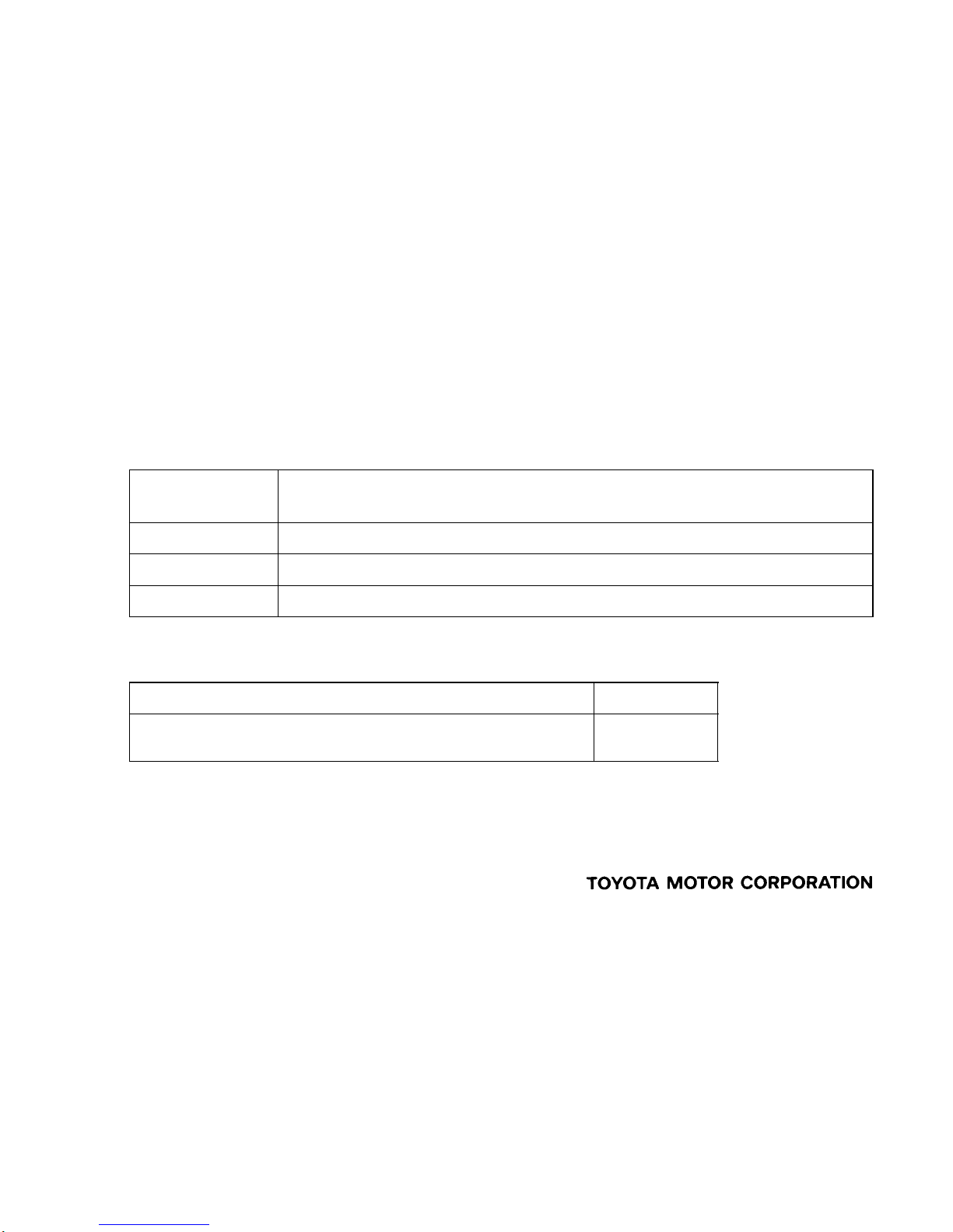
This hybrid transaxle consists primarily of MG1, MG2, a compound gear unit (which consists of a motor
speed reduction planetary gear unit and a power split planetary gear unit), a counter gear unit, and a
differential gear unit.
The engine, MG1 and MG2 are mechanically joined via the compound gear unit.
The compound gear unit contains a motor speed reduction planetary gear unit and a power split planetary
gear unit. The motor speed reduction planetary gear unit reduces the rotational speed of MG2, and the
power split planetary gear unit splits the motive force of the engine two ways: one to drive the wheels, an d
the other to drive MG1, so that it can function as a generator.
In the motor speed reduction planetary gear unit, the sun gear is coupled to the output shaft of MG2, and
the carrier is fixed. Furthermore, the compound gear unit uses a compound gear, in which two planetary
ring gears, a counter drive gear, and a parking gear are integrated.
For details, refer to P311 Hybrid Transaxle on page CH-2.
Image Diagram
THS II (TOYOTA HYBRID SYSTEM II)
277TH11
Accelerator Pedal
Position Sensor
THS ECU
Throttle Control
Motor
Throttle
Valve
Throttle Position
Sensor
TH-5
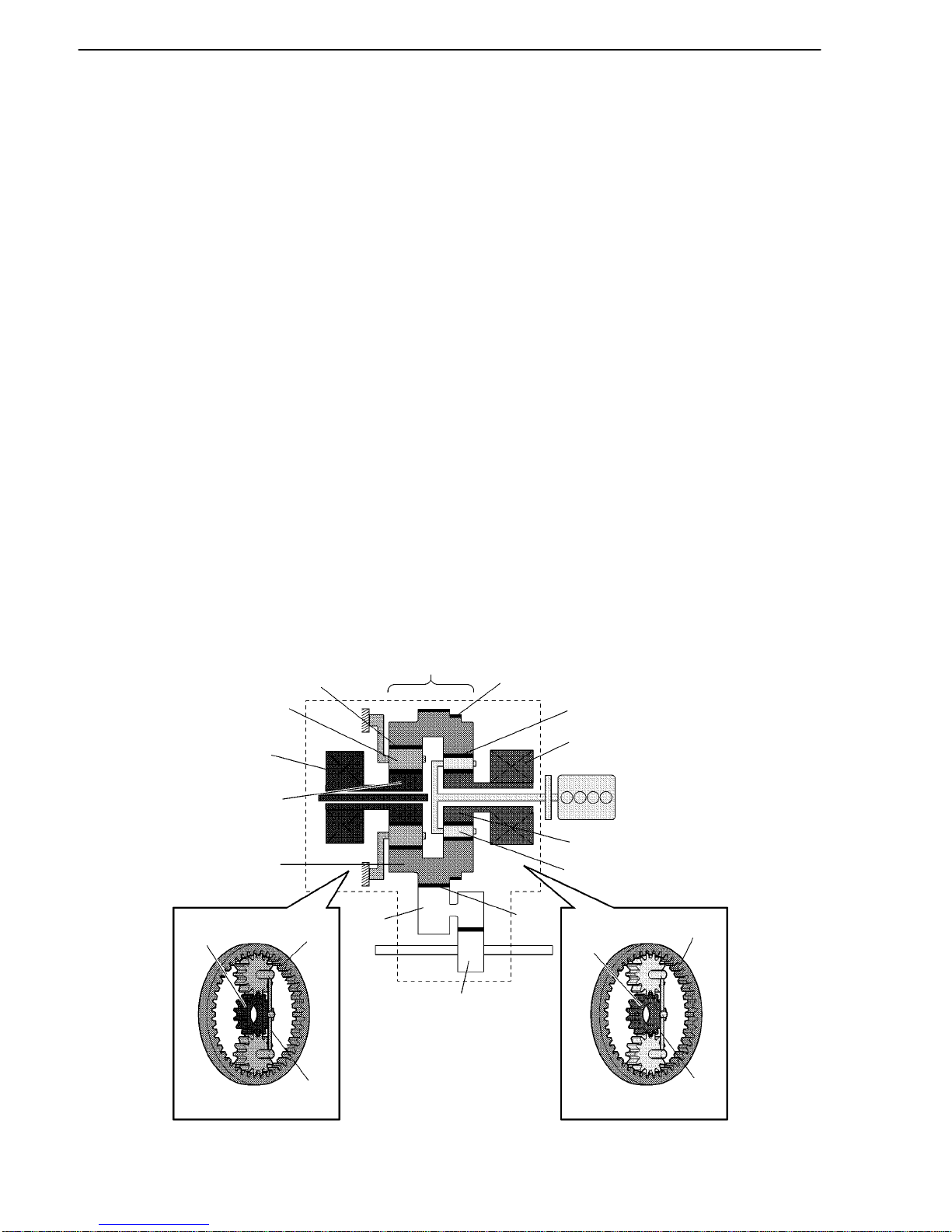
5. Link-Less
The ETCS-i (Electronic Throttle Control System-intelligent) is used. This is a link-less system that does not
use an accelerator cable. Instead, it uses an accelerator pedal position sensor and a throttle position sensor
to detect the accelerator pedal position and the throttle position.
The THS ECU calculates the target engine speed and the required engine motive force in accordance with
the signals provided by the accelerator pedal position sensor, vehicle driving conditions, and the SOC (state
of charge) of the battery. Based on the results of this calculation, the THS ECU optimally controls the throttle
valve. For details, refer to 2AZ-FXE engine on page EG-43.
6. Regenerative Brake
The regenerative brake function operates MG2 as a generator while the vehicle is decelerating or braking and
stores this electrical energy in the HV battery.
For details, refer to Outline of Regenerative Brake Cooperative Control Function in the Brake Control
System, on page CH-28.
THS II (TOYOTA HYBRID SYSTEM II)
02HTH03TE
: Electrical Path
: Mechanical
Power Path
Engine
Compound
Gear Unit
MG1
MG2
Inverter
Assembly
HV
Battery
02HTH04TE
Engine
Compound
Gear Unit
MG1
MG2
Inverter
Assembly
HV
Battery
02HTH05TE
Engine
Compound
Gear Unit
MG1
MG2
Inverter
Assembly
HV
Battery
02HTH06TE
Engine
Compound
Gear Unit
MG1
MG2
Inverter
Assembly
HV
Battery
TH-6
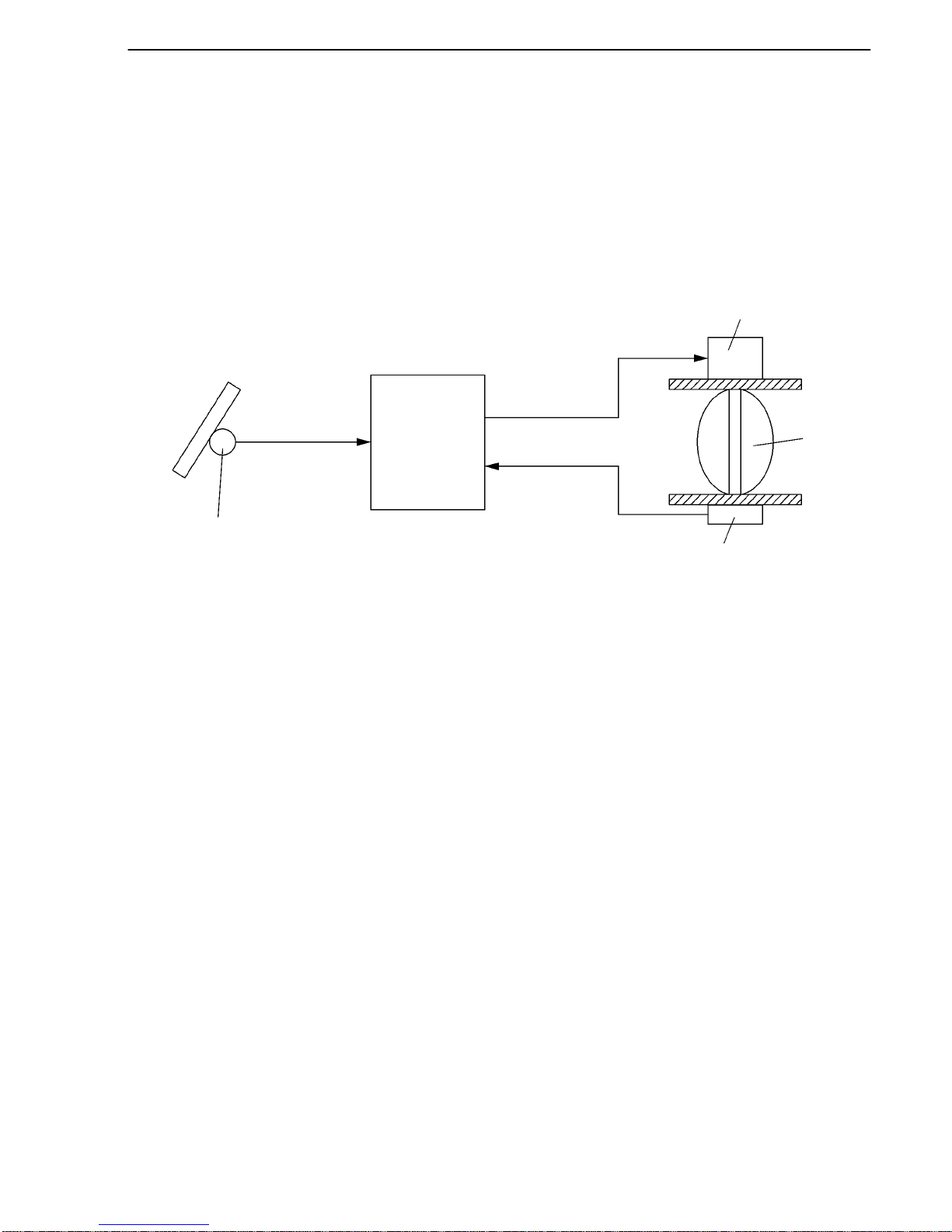
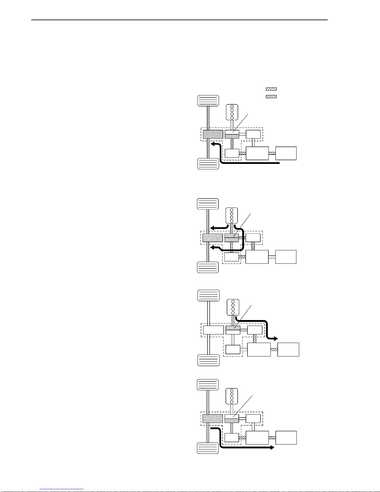
7. Basic Operation
This system generates a motive force in combination with the engine, MG1 and MG2 in accordance with the
driving conditions. Representative examples of the various combinations are described below.
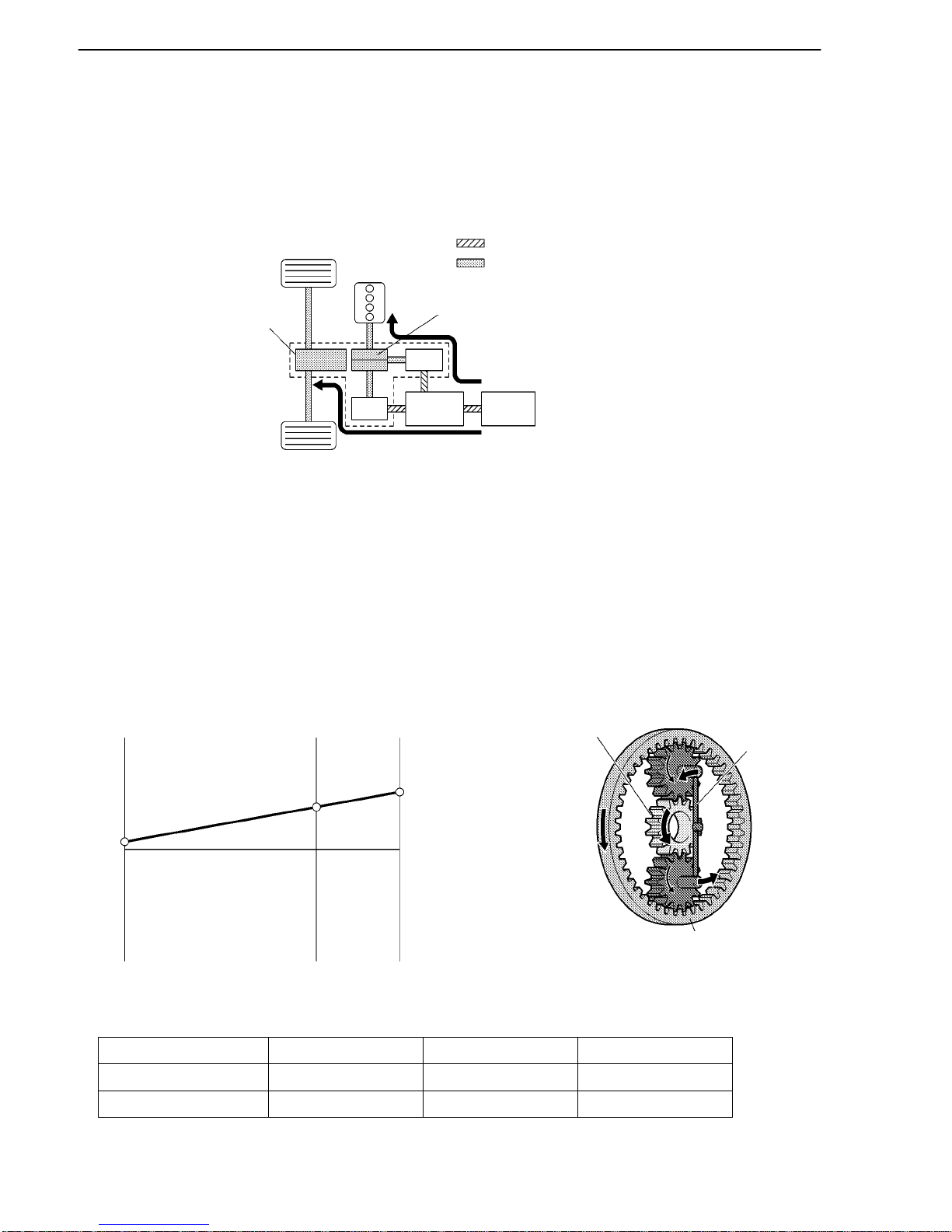
Starting (Drive by MG2)
Supply of electrical power from the HV battery
to MG2 provides force to drive the front wheels.
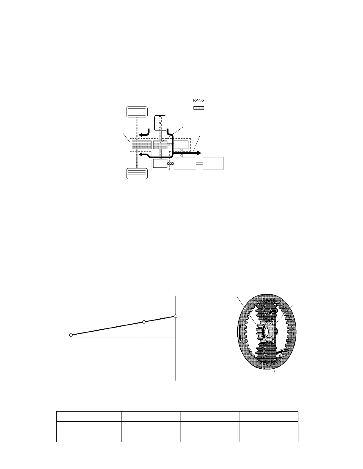
During Acceleration with Engine
While the front wheels are being driven by the
engine via the planetary gears, MG1 is driven by
the engine via the planetary gears, in order to
supply the generated electricity to MG2.
Charge The HV Battery
MG1 is rotated by the engine via the planetary
gears, in order to charge the HV battery.
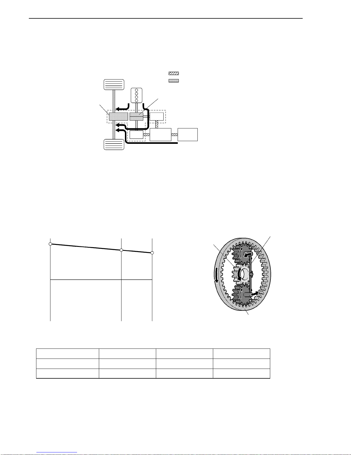
During Deceleration Driving
When the vehicle is decelerating, kinetic energy
from the front wheels is recovered and converted
into electrical energy and used to recharge the
HV battery by means of MG2.

THS II (TOYOTA HYBRID SYSTEM II)
02HTH07Y
Circuit Breaker
Sensors
Shift Position
Sensor
Accelerator
Pedal Position
Sensor
Yaw Rate &
Deceleration
Rate Sensor
Steering Angle
Sensor
Speed Sensor
Brake Pedal
Stroke Sensor
Skid Control
ECU
Regenerative
Brake
Force Request
Actual
Regenerative
Braking
Control Value
Engine
MG1
Brake
Actuator
MG2
THS ECU
Inverter Assembly
Inverter
MG ECU
Boost
Converter
DC/DC
Converter
Resistor
SMRP
: CAN (CAN No.1 Bus)
: Mechanical Power Path
: Hydraulic Power Path
: Power Cable
(High-voltage, High-amperage)
: Electrical Signal
A/C
Inverter
Electrical Inverter
Compressor
(For A/C)
SMRG SMRB
Auxiliary
Battery
Battery Temperature
Sensor
Current Sensor
Battery
Smart
Unit
HV
Battery
TH-7
SYSTEM DIAGRAM
THS II (TOYOTA HYBRID SYSTEM II)
02HTH08TE
Combination Meter
Steering Angle
Sensor
A/C ECU
Skid Control
ECU
Accelerator Pedal
Position Sensor
Stop Light Switch
DLC3
Airbag Sensor
Assembly
Yaw Rate and
Deceleration Rate
Sensor
Front Circuit
Breaker Sensor
Inverter Assembly
Boost Converter
Inverter
MG ECU
THS ECU
Auxiliary
Battery
Water Pump
(for Inverter,
MG1 and MG2)
Shift Position
Sensor
Hybrid Transaxle
MG1
MG2
HV Battery Unit
HV Battery
DC/DC Converter
Battery Smart Unit
Service Plug
TH-8
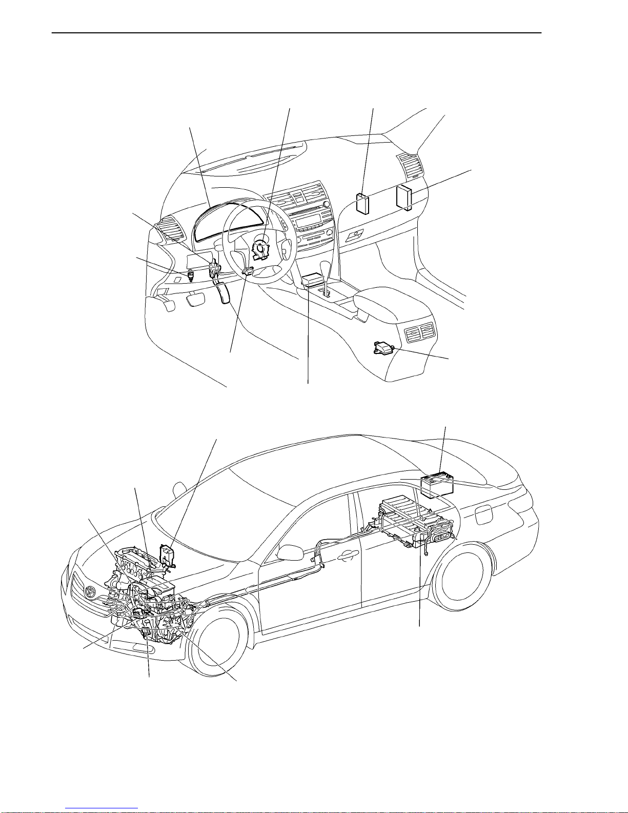
LAYOUT OF MAIN COMPONENTS
THS II (TOYOTA HYBRID SYSTEM II)
TH-9
FUNCTION OF MAIN COMPONENTS
Item Outline
MG1
MG1, which is driven by the engine, generates high-voltage
electricity in order to operate MG2 or charge the HV
battery. Also, it functions as a starter to start the engine.
MG1 operates so that the gear ratio of the power split
planetary gear unit will optimally suit the driving
conditions of the vehicle.
Hybrid
Transaxle
MG2
Driven by electrical power from MG1 or HV battery, and
generates motive force for the front wheels.
During braking, or when the accelerator pedal is not
depressed, it generates electricity to recharge the HV
battery (Regenerative brake control).
Transaxle
Power
Split
Planetary
Gear
Distributes the engine’s drive force as appropriate to directly
drive the vehicle as well as the generator.
Compound
Gear Unit
Motor
Speed
Reduction
Planetary
Gear
Located between MG2 and the power split planetary gear, the
motor speed reduction planetary gear reduces the rotational
speed of MG2 in accordance with the characteristics of the
planetary gear, in order to increase torque.
HV Battery
Supplies electrical power to the MG1 and MG2 in
accordance with the driving conditions of the vehicle.
Is recharged by the MG1 and MG2 in accordance with the
SOC and the driving conditions of the vehicle.
HV Battery
Unit
DC/DC Converter
Drops the maximum voltage of DC 244.8 V into DC12 V in
order to supply electricity to body electrical components, as
well as to recharge the auxiliary battery (DC 12 V).
Battery Smart Unit
Monitors the conditions of the HV battery and transmits them
to the THS ECU.
Service Plug
Shuts off the high-voltage circuit of the HV battery when this
plug is removed for vehicle inspection or maintenance.
Inverter Assembly
A device that converts the high-voltage DC (HV battery) into
AC (MG1 and MG2) and vice versa (Converts AC into DC).
Boost Converter
Boosts the maximum voltage of the HV battery from DC 244.8
V to DC 650 V and vice versa (drops DC 650 V to DC 244.8
V).
MG ECU
Controls the inverter and boost converter in accordance with
the signals received from the THS ECU, thus driving MG1 or
MG2 or causing them to generate electricity.
THS ECU
Effects comprehensive control of the THS II.
Information from each sensor as well as from the ECU
(battery smart unit, skid control ECU, and EPS ECU) is
received, and based on this the required torque and output
power is calculated. The THS ECU sends the calculated
result to the inverter assembly and skid control ECU.
Activates the ETCS-i (Electronic Throttle Control
System-intelligent) in accordance with the target engine
speed and required engine motive force.
Monitors the charging condition of the HV battery.
Controls the cooling fan of the HV battery and cooling fan
of the DC/DC converter.
Controls the DC/DC converter.
(Continued)

THS II (TOYOTA HYBRID SYSTEM II)
TH-10
Item
Outline
Skid Control ECU
During braking, it calculates the regenerative brake force
that is required for control and transmits it to the THS ECU.
Calculates the motive force that is required for control
during the operation of TRAC or VSC and transmits it to the
THS ECU.
Accelerator Pedal Position Sensor
Converts the accelerator pedal position into an electrical
signal and outputs it to the THS ECU.
Shift Position Sensor
Converts the shift position into an electrical signal and outputs
it to the THS ECU.
SMR
(System Main Relay)
Connects and disconnects the high-voltage power circuit
between the H V b attery and inverter assembly, through the use
of a signal from the THS ECU.
Interlock Switch
(for Inverter Cover and Service Plug)
Verifies that the cover of both the inverter and the service plug
have been installed.
Circuit Breaker Sensor
Detects the impact that is applied to the vehicle during a
collision and transmits a signal to the THS ECU. Upon
receiving this signal, the THS ECU operates the SMR (System
Main Relay) to shut down the power supply.
Auxiliary Battery
Charged by the HV battery module power via the DC /DC
converter. Supplies power to the audio system, air
conditioning system (except the electric inverter compressor)
and the ECUs.

THS II (TOYOTA HYBRID SYSTEM II)
02DTH85Y
Vehicle
Speed
(A) (B) (C) (D) (E) (F)
(G)
Time
Flat
Road
Downhill
Road
Flat Road
Driving Condition
(A): READY ON State
(B): Starting with MG2 (See Page TH-13)
(C): Running with MG2 and Engine (See Page TH-14)
(D): During Low Load and Constant-Speed Cruising (See Page TH-15)
(E): During Full Throttle Acceleration (See Page TH-16)
(F): During Deceleration Driving (See Page TH-17)
(G): During Reverse Driving (See Page TH-18)
TH-11
SYSTEM OPERATION
1. General
The THS II uses two sources of motive force, the engine and MG2, and uses MG1 as a generator. The
system optimally combines these forces in accordance with the various driving conditions.
The THS ECU constantly monitors the SOC condition, the HV battery temperature, the coolant
temperature, and the electrical load condition. If any one of the monitored items fails to satisfy the
requirements when the READY indicator is ON and the shift lever is in the “P” position, or the vehicle
is driven in reverse, the THS ECU to starts the engine to drive MG1, and then charges the HV battery.
The THS II drives the vehicle by optimally combining the operations of the engine, MG1, and MG2 in
accordance with the driving conditions listed below.
The vehicle conditions listed below are examples of typical vehicle running conditions.
THS II (TOYOTA HYBRID SYSTEM II)
02DTH90Y
Sun Gear
(MG1)
Carrier
(Engine)
Ring Gear
(Output)
rpm
0
(+)(+)(+)
(-)(-)(-)
02DTH97Y
Sun Gear
(MG1)
Carrier
(Engine)
Ring Gear
(Output)
TH-12
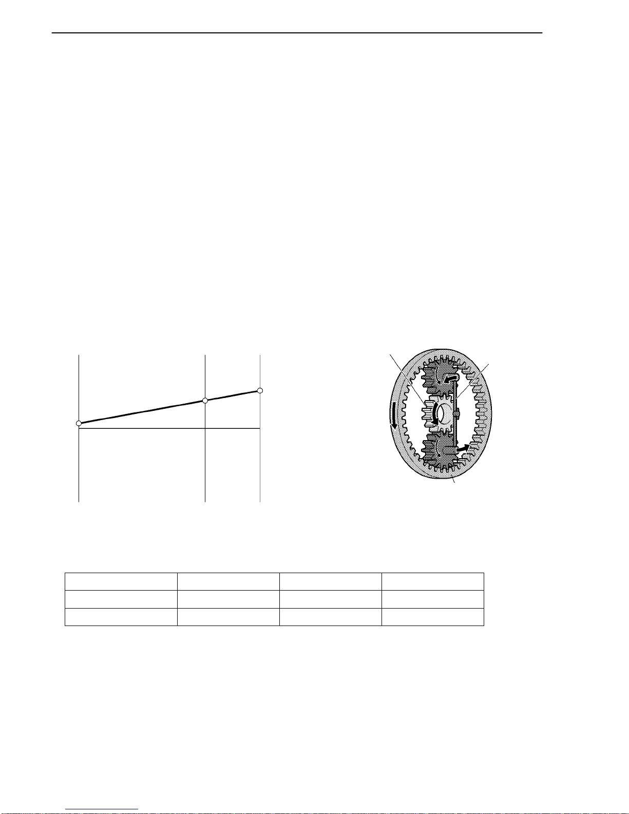
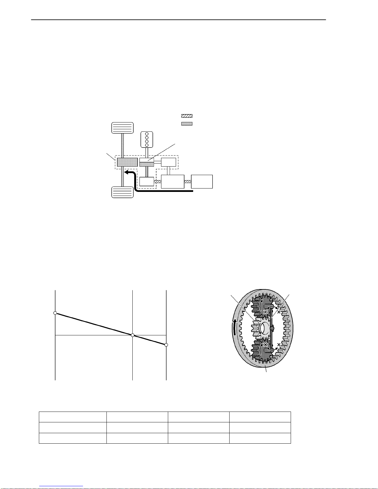
2. How to Read a Nomographic Chart
The nomographic chart below gives a visual representation of the planetary gear’s rotational direction,
rotational speed, and torque balance.
In the nomographic chart, a straight line is used to represent the relationship between the rotational speeds
of the 3 gears in the power split planetary gear unit. The rotational speed of each gear is indicated by the
distance from the 0 rpm point. Due to the structure of the power split planetary gear unit, the relationship
between the rotational speeds of the 3 gears is always expressed by a straight line.
The relationship between the gear rotation directions and the torque that acts on each gear is as described
below.
Due to the structure of this hybrid transaxle, the MG2 motive force acts on the ring gear via the motor speed
reduction planetary gear unit. The illustrations of the power split planetary gear unit operation on the
following pages, represent the rotational direction, rotational speed and torque condition that act on the
ring gear.
The nomographic charts and the illustrations of the power split planetary gear unit operation for each
vehicle running condition shown on the following pages represent one situation as an example.
Nomographic Chart Power Split Planetary Gear Unit Operation
Condition of Power Split Planetary Gear Unit
Sun Gear (MG1) Carrier (Engine) Ring Gear (Output)
Rotational Direction + + +
Torque Condition - + -
Normal Driving (During Low Load and Constant-speed Cruising)
THS II (TOYOTA HYBRID SYSTEM II)
02HTH11TE
Hybrid
Transaxle
Front
Wheel
: Electrical Path
: Mechanical Power Path
Engine
Compound
Gear Unit
MG1
MG2
Inverter
Assembly
HV
Battery
02DTH86Y 02DTH99Y
Sun Gear
(MG1)
Carrier
(Engine)
Ring Gear
(Output)
rpm
0
(+)(+)(+)
(-)(-)(-)
Sun Gear
(MG1)
Carrier
(Engine)
Ring Gear
(Output)
TH-13
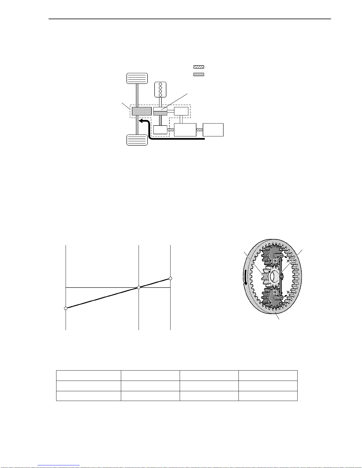
3. Starting with MG2/(B)
When the vehicle is started off, the vehicle operates powered only by the MG2.
When the vehicle starts off under normal conditions, it runs using the motive force of MG2. While running
under this condition, the rotational speed of the carrier is 0 rpm due to the engine being inactive. In
addition, since MG1 does not generate any torque, no torque acts on the sun gear. However, the sun gear
rotates freely in the (-) direction balancing the rotating ring gear (Output).
Nomographic Chart Power Split Planetary Gear Unit Operation
Condition of Power Split Planetary Gear Unit
Sun Gear (MG1) Carrier (Engine) Ring Gear (Output)
Rotational Direction - 0 +
Torque Condition 0 0 +
THS II (TOYOTA HYBRID SYSTEM II)
02HTH12TE
Hybrid
Transaxle
Front
Wheel
: Electrical Path
: Mechanical Power Path
Engine
Compound
Gear Unit
MG1
MG2
Inverter
Assembly
HV
Battery
02DTH90Y 02DTH97Y
Sun Gear
(MG1)
Carrier
(Engine)
Ring Gear
(Output)
rpm
0
(+)(+)(+)
(-)(-)(-)
Sun Gear
(MG1)
Carrier
(Engine)
Ring Gear
(Output)
TH-14
4. Running with MG2 and Engine/(C)
If the required drive torque increases when running with MG2 only, MG1 is activated to start the engine.
In addition, if any one of the items monitored by the THS ECU such as the SOC condition, the battery
temperature, the engine coolant temperature or the electrical load condition deviates from the specified
level, MG1 is activated to start the engine.
Only when running with MG2, when the engine starts with MG1, the torque acts on the sun gear (MG1)
in the (+) direction, the carrier (Engine) rotates in the (+) direction in reaction to the torque transmitted
by the sun gear. The ring gear rotates in the (+) direction in reaction to the carrier rotation.
The nomographic charts and the illustrations of the power split planetary gear unit operation for each
vehicle running condition shown on the following pages represent one situation as an example.
Nomographic Chart Power Split Planetary Gear Unit Operation
Condition of Power Split Planetary Gear Unit
Sun Gear (MG1) Carrier (Engine) Ring Gear (Output)
Rotational Direction + + +
Torque Condition + - +
THS II (TOYOTA HYBRID SYSTEM II)
02HTH14TE
Hybrid
Transaxle
Front
Wheel
: Electrical Path
: Mechanical Power Path
Engine
Compound
Gear Unit
MG1
MG2
Inverter
Assembly
HV
Battery
When SOC level is low.
02DTH90Y 02DTH97Y
Sun Gear
(MG1)
Carrier
(Engine)
Ring Gear
(Output)
rpm
0
(+)(+)(+)
(-)(-)(-)
Sun Gear
(MG1)
Carrier
(Engine)
Ring Gear
(Output)
TH-15
5. During Low Load and Constant-Speed Cruising/(D)
When the vehicle is running under low load and constant-speed cruising conditions, the motive force of
the engine is transmitted by the planetary gears. Some of this motive force is output directly, and the
remaining motive force is used for generating electricity through MG1. Through the use of the electrical
path of an inverter, this electrical power is transmitted to MG2 to be output as the motive force of MG2.
If the SOC level of the HV battery is low, it is charged by MG1 driven by the engine.
The following represents an example of the power split planetary gear unit operation under normal driving
conditions. The sun gear, carrier and ring gear rotate in the (+) direction. The torque from the engine acts
on the carrier (Engine) in the (+) direction, causing the sun gear and ring gear to react in the (-) direction.
MG1 generates electricity by harnessing the (-) torque that acts on the sun gear.
The nomographic charts and the illustrations of the power split planetary gear unit operation for each
vehicle running condition shown on the following pages represent one situation as an example.
Nomographic Chart Power Split Planetary Gear Unit Operation
Condition of Power Split Planetary Gear Unit
Sun Gear (MG1) Carrier (Engine) Ring Gear (Output)
Rotational Direction + + +
Torque Condition - + -
THS II (TOYOTA HYBRID SYSTEM II)
02HTH16TE
Hybrid
Transaxle
Front
Wheel
: Electrical Path
: Mechanical Power Path
Engine
Compound
Gear Unit
MG1
MG2
Inverter
Assembly
HV
Battery
02DTH91Y 02DTH98Y
Sun Gear
(MG1)
Carrier
(Engine)
Ring Gear
(Output)
rpm
0
(+)(+)
(+)
(-)(-)(-)
Sun Gear
(MG1)
Carrier
(Engine)
Ring Gear
(Output)
TH-16
6. During Full Throttle Acceleration/(E)
When the vehicle driving condition changes from low load cruising to full-throttle acceleration, the system
supplements the motive force of MG2 with electrical power from the HV battery.
When more engine power is required, in order to increase the engine speed, the rotation speeds of the
related gears change as follows. The directions in which the torque acts on each gear are the same as those
described in “During Low Load and Constant-speed Cruising”.
Nomographic Chart Power Split Planetary Gear Unit Operation
Condition of Power Split Planetary Gear Unit
Sun Gear (MG1) Carrier (Engine) Ring Gear (Output)
Rotational Direction + + +
Torque Condition - + +
THS II (TOYOTA HYBRID SYSTEM II)
02HTH17TE
Hybrid
Transaxle
Front
Wheel
: Electrical Path
: Mechanical Power Path
Engine
Compound
Gear Unit
MG1
MG2
Inverter
Assembly
HV
Battery
02DTH86Y 02DTH99Y
Sun Gear
(MG1)
Carrier
(Engine)
Ring Gear
(Output)
rpm
0
(+)(+)(+)
(-)(-)(-)
Sun Gear
(MG1)
Carrier
(Engine)
Ring Gear
(Output)
TH-17
7. During Deceleration Driving/(F)
Deceleration in “D” Range
While the vehicle is decelerated with the shift lever in the D position, the engine is turned OFF and the
motive force changes to zero. At this time, the wheels drive MG2, causing MG2 to operate as a generator,
charging the HV batteries.
If the vehicle decelerates from a higher speed, the engine maintains a predetermined speed without
stopping, in order to protect the planetary gear unit.
During deceleration, the ring gear is rotated by the rear wheels. Under this condition, due to the engine
being inactive, the rotational speed of the carrier is 0 rpm. In addition, since MG1 does not generate any
torque, no torque acts on the sun gear. However, the sun gear (MG1) rotates freely in the (-) direction
balancing the rotating ring gear (Output).
Nomographic Chart Power Split Planetary Gear Unit Operation
Condition of Power Split Planetary Gear Unit
Sun Gear (MG1) Carrier (Engine) Ring Gear (Output)
Rotational Direction - 0 +
Torque Condition 0 0 0
THS II (TOYOTA HYBRID SYSTEM II)
02HTH11TE
Hybrid
Transaxle
Front
Wheel
: Electrical Path
: Mechanical Power Path
Engine
Compound
Gear Unit
MG1
MG2
Inverter
Assembly
HV
Battery
02DTH94Y
02DTH100Y
Sun Gear
(MG1)
Carrier
(Engine)
Ring Gear
(Output)
rpm
0
(+)(+)(+)
(-)(-)(-)
Sun Gear
(MG1)
Carrier
(Engine)
Ring Gear
(Output)
TH-18
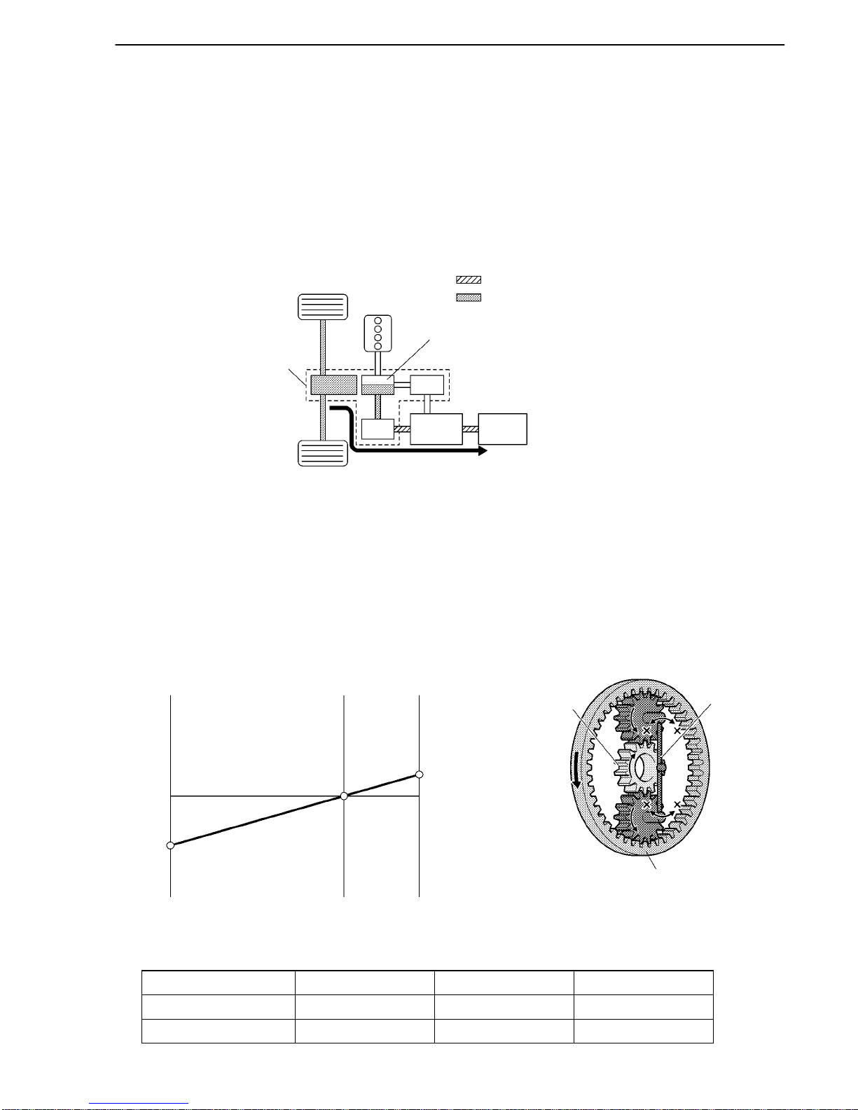
8. During Reverse Driving/(G)
When the vehicle is being driven in reverse, the required power is supplied by MG2. At this time, MG2
rotates in the opposite direction, the engine remains stopped, and MG1 rotates in the normal direction
without generating any electricity.
During reverse driving, when any of the SOC condition, battery temperature, engine coolant temperature
and electrical load condition reaches a specified level, the engine may start. The following illustration
represents the condition when the engine is not running.
The conditions of the planetary gear are opposite to those described in “Starting and Running with MG2”.
Due to the engine being inactive, the rotational speed of the carrier is 0 rpm but the sun gear (MG1) rotates
freely in the (+) direction balancing the rotating ring gear (Output).
Nomographic Chart Power Split Planetary Gear Unit Operation
Condition of Power Split Planetary Gear Unit
Sun Gear (MG1) Carrier (Engine) Ring Gear (Output)
Rotational Direction + 0 Torque Condition 0 0 -
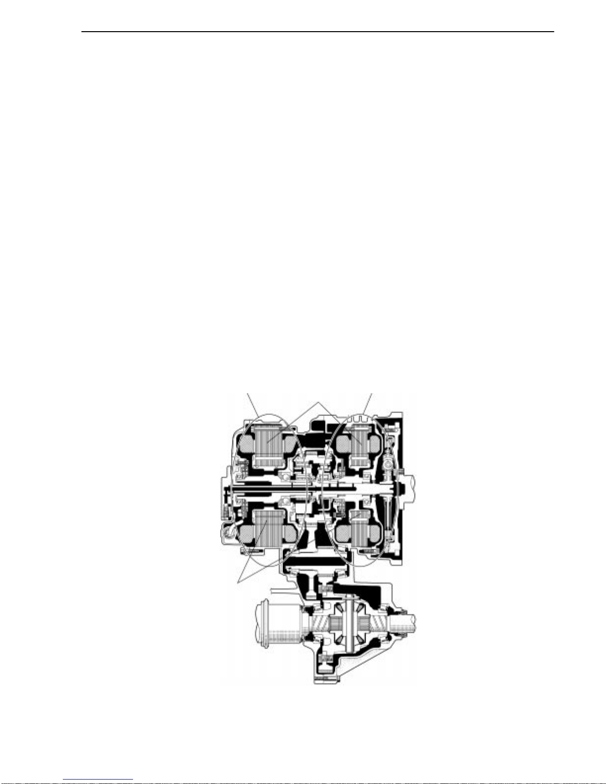
THS II (TOYOTA HYBRID SYSTEM II)
02HCH31Y
MG2
Stator
MG1
Rotor
Hybrid Transaxle
TH-19
CONSTRUCTION OF MAIN COMPONENTS
1. MG1 and MG2
General
Serving as the source of supplemental motive force that provides power assistance to the engine as
needed, the electric motor helps the vehicle achieve excellent dynamic performance, including smooth
start-offs and acceleration. When the regenerative brake is activated, MG2 (Motor Generator No.2)
converts the vehicle’s kinetic energy into electrical energy, which is then stored in the HV battery.
MG1 (Motor Generator No.1) recharges the HV battery and supplies electrical power to drive MG2. In
addition, by regulating the amount of electrical power generated (thus varying the generator’s rpm), MG1
effectively controls the continuously variable transmission function of the transaxle. MG1 also serves
as the starter to start the engine.
Both the MG1 and MG2 are compact, lightweight, and highly efficient alternating current permanent
magnet synchronous type.
Both the MG1 and MG2 use a rotor containing a V -shaped, high-magnetic force permanent magnet that
maximizes the generation of reduction torque. They use a stator made of a low core-loss electromagnetic
steel sheet and a high voltage resistant winding wire. Through these measures, the MG1 and MG2 have
realized high output and torque in a compact construction.
A cooling system via water pump for the MG1 and MG2 has been added. For details, refer to the cooling
system (for Inverter, MG1 and MG2) on page TH-27.

THS II (TOYOTA HYBRID SYSTEM II)
02HTH22Y
MG1
W
UV
MG2
W
UV
IPM for MG1
and MG2
Current
Sensor
Current
Sensor
Power Transistor
Inverter
TH-20
MG1 Specifications
Type Permanent Magnet Motor
Function Generate, Engine Starter
Maximum System Voltage* DC 650 V
Cooling System Water-cooled
MG2 Specifications
Type Permanent Magnet Motor
Function Generate, Drive Front Wheels
Maximum System Voltage* DC 650 V
Maximum Output 105 kW (141 HP)
Maximum Torque 270 N.m (199 ft.lbf)
Cooling System Water-cooled
*: These voltage are converted into an alternating current and then supplied to MG1and MG2.
System Diagram
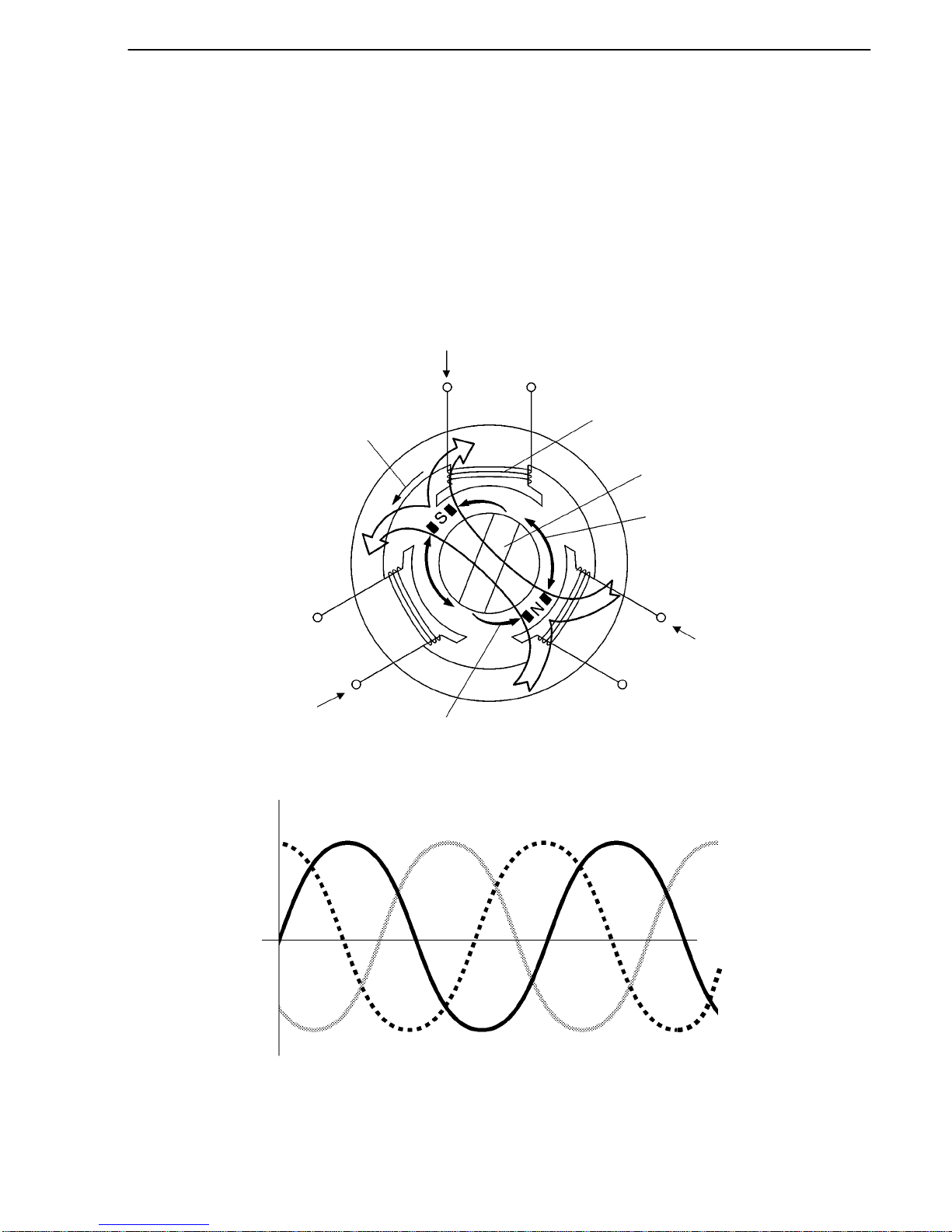
THS II (TOYOTA HYBRID SYSTEM II)
182TH29
U Phase
Rotational
Magnetic Field
#
V Phase
Attraction
#
W Phase
Repulsion
Rotor
Stator Coil
#
N
S
: From inverter
# : Connected internally in the motor
277TH47
(+)
(-)
U
V
W
Three-phase Alternating Current Output Waveforms
TH-21
Permanent Magnet Motor (for MG1 and MG2)
When a three-phase alternating current is passed through the three-phase windings of the stator coil, a
rotational magnetic field is created in the electric motor. By controlling this rotating magnetic field
according to the rotor’s rotational position and speed, the permanent magnets that are provided in the
rotor become attracted by the rotating magnetic field, thus generating torque.
The generated torque is for all practical purposes proportionate to the amount of current, and the
rotational speed is controlled by the frequency of the alternating current.
Furthermore, a high level of torque, all the way to high speeds, can be generated efficiently by properly
controlling the rotating magnetic field and the angles of the rotor magnets.
When the motor generates electricity, the rotor rotates to create a magnetic field, which creates a current
in the stator coil.
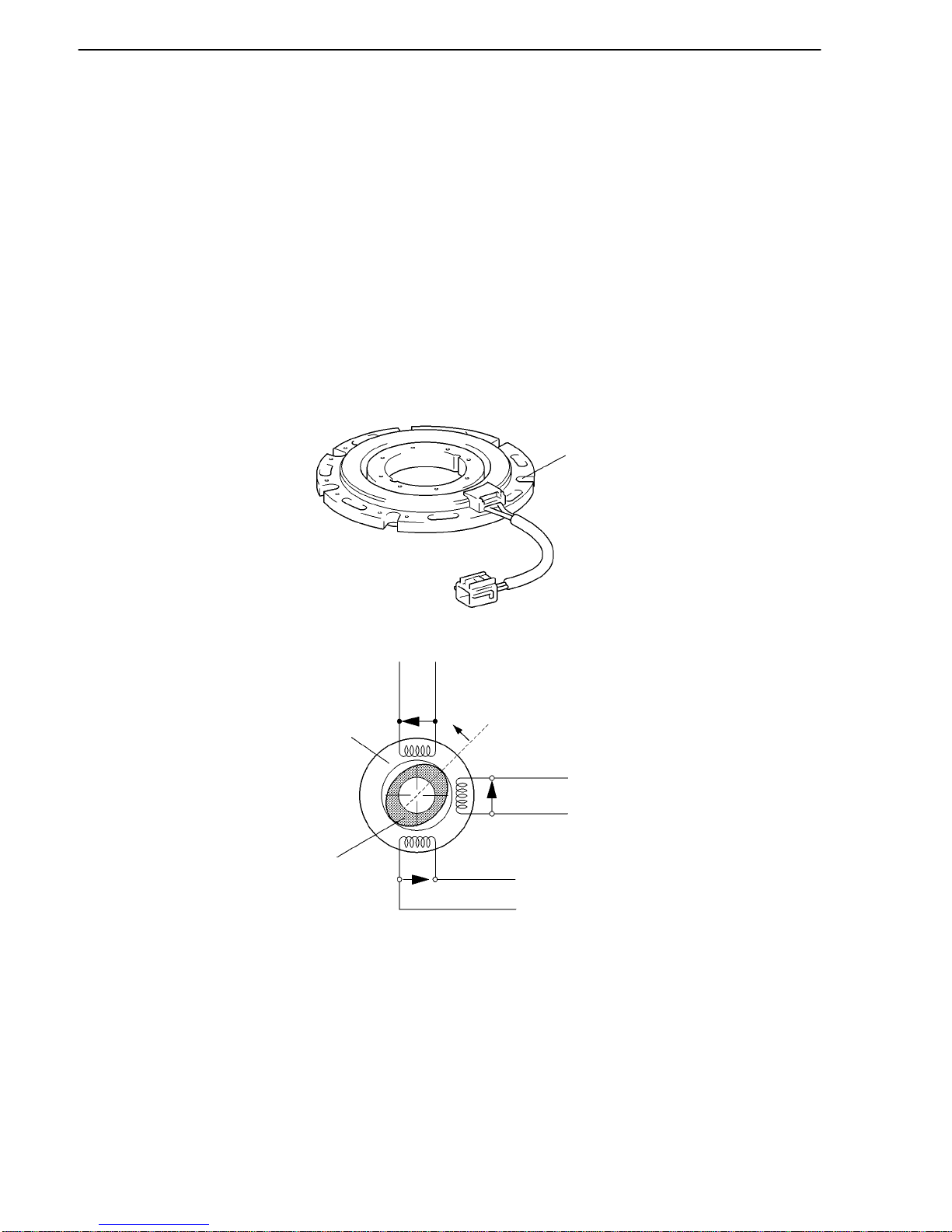
THS II (TOYOTA HYBRID SYSTEM II)
277TH104
Speed Sensor (Resolver)
Excitation
Coil A
Stator
Rotor
Detection
Coil S
Detection
Coil C
TH-22
Speed Sensor/Resolver (for MG1 and MG2)
This is an extremely reliable and compact sensor that precisely detects the magnetic pole position, which
is indispensable for ensuring the efficient control of MG1 and MG2.
The stator of the sensor contains three types of coils: excitation coil A, detection coil S, and detection
coil C. The detection coils S and C are electrically staggered 90 degrees.
The rotor is oval, the distance of the gap between the stator and the rotor varies with the rotation of the
rotor.
The flow of an alternating current into an excitation coil A results in the output of signals of a constant
frequency. Coil S and coil C output values that correspond to the position of the rotor. Therefore, the MG
ECU detects the absolute position based on the difference between the coil S and coil C output values.
Furthermore, the MG ECU calculates the rotational speed based on the amount of change in the position
within a given length of time.

THS II (TOYOTA HYBRID SYSTEM II)
277TH105
(+)
Excitation
Coil A
(-)
(+)
Detection
Coil S
(-)
Virtual Waveform
(+)
Detection
Coil C
(-)
Virtual Waveform
0 180
TH-23
Because an alternating current flows from this resolver to the excitation coil at a constant frequency, a
constant frequency is output to the coils S and C, regardless of the rotor speed. The rotor is oval, and the
distance of the gap between the stator and the rotor varies with the rotation of the rotor. Consequently,
the peak values of the waveforms output by the coils S and C vary in accordance with the position of the
rotor.
The MG ECU constantly monitors these peak values, and connects them to form a virtual waveform. The
MG ECU calculates the absolute position of the rotor from the difference between the values of the coils
S and C. It determines the rotor direction based on the difference between the phases of the virtual
waveform of the coil S and the virtual waveform of the coil C. Furthermore, the MG ECU calculates the
rotational speed based on the amount of change in the rotor position within a given length of time.
The diagrams below illustrate the waveforms that are output at coils A, S, and C when the rotor makes
a positive rotation of 180 from a certain position.
THS II (TOYOTA HYBRID SYSTEM II)
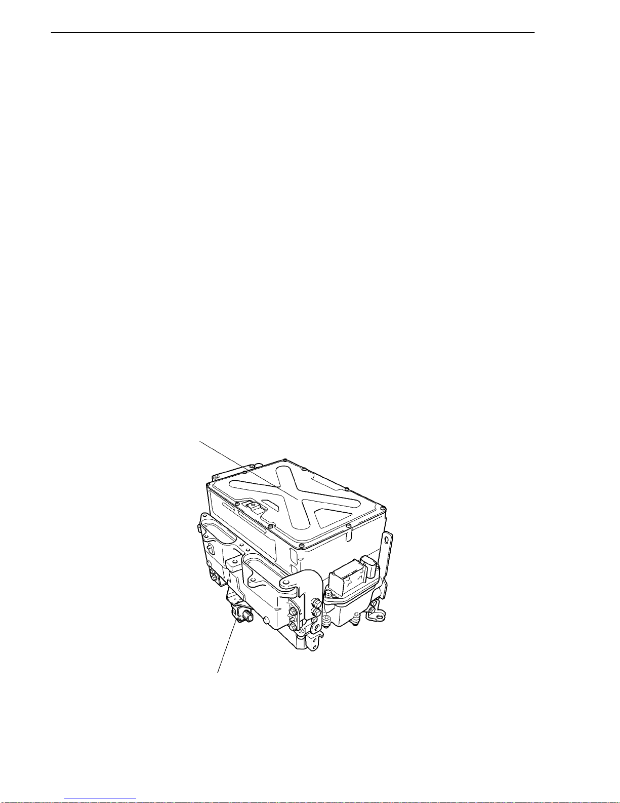
02HTH23Y
Inverter Assembly
(Included Inverter,
Boost Convert
and MG ECU)
Circuit Breaker
Sensor (for Front)
TH-24
2. Inverter Assembly
General
The inverter converts the high-voltage direct current of the HV battery into three-phase alternating
current for driving MG1 and MG2.
The activation of the power transistors is controlled by the THS ECU, via the MG ECU. In addition, the
inverter transmits information that is needed for current control, such as the output amperage or voltage,
to the THS ECU via the MG ECU.
T ogether with MG1 and MG2, the inverter is cooled by the dedicated radiator of the coolant system that
is separate from that of the engine.
In the event of a collision involving the vehicle, the circuit breaker sensor, which is installed on the
inverter, detects a collision signal in order to stop the system. For details, refer to During Collision
Control on page TH-54.
A boost converter is used in the inverter assembly, in order to boost the nominal voltage output by the
HV battery from DC 244.8 V to maximum voltage of DC 650 V. After the voltage is boosted, the inverter
converts the direct current into an alternating current.
Each of the bridge circuits for MG1 and MG2 contains 6 power transistors. In addition, a signal
processor /protective function processor has been integrated into a compact IPM (Intelligent Power
Module) for driving the vehicle.
For details on the multiple functions of the inverter, refer to Inverter Assembly Control on page TH-49.
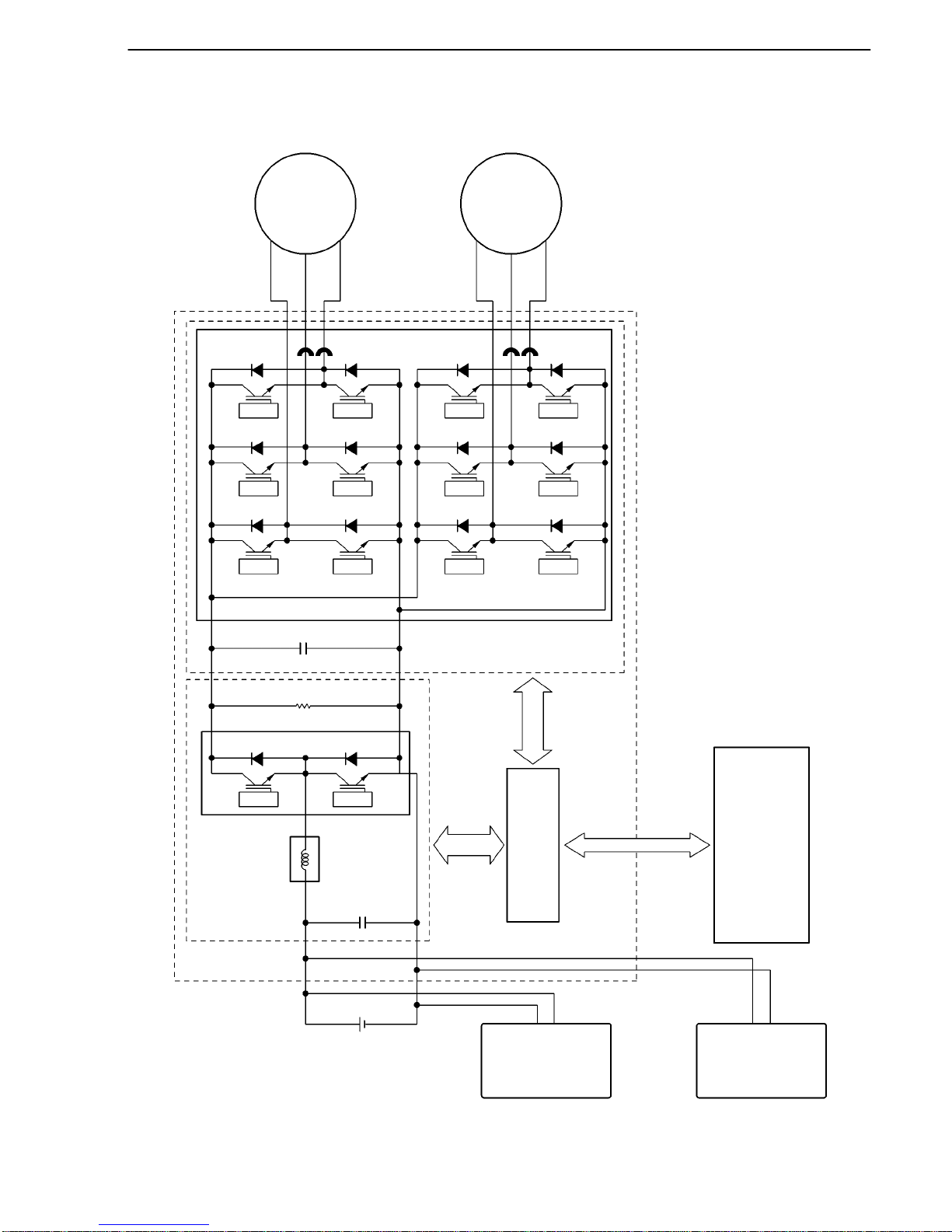
THS II (TOYOTA HYBRID SYSTEM II)
02HTH24Y
MG1
U
V
W
MG2
U
V
W
IPM for MG1
& MG2
Current
Sensor
Power
Transistor
Current
Sensor
Inverter
Boost IPM
Boost
Converter
Inverter
Assembly
Reactor
HV battery
MG
ECU
DC/DC
Converter
THS
ECU
A/C Inverter
TH-25
System Diagram
THS II (TOYOTA HYBRID SYSTEM II)
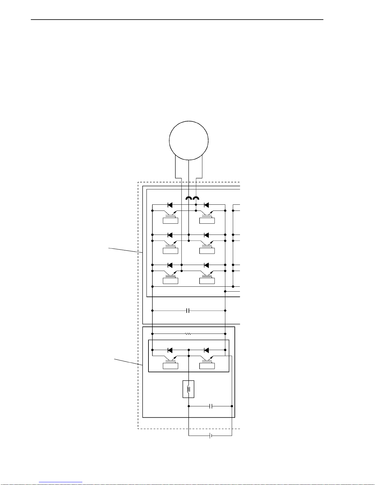
02HTH45Y
MG1
Inverter
Boost
Converter
Boost IPM
IGBT IGBT
Reactor
HV Battery
TH-26
Boost Converter
This boost converter boosts the nominal voltage of DC 244.8 V that is output by the HV battery to the
maximum voltage of DC 650 V. The converter consists of the boost IPM (Intelligent Power Module) with
a built-in IGBT (Insulated Gate Bipolar Transistor) which performs the switching control, and the reactor
which stores energy. By using these components, the converter boosts the voltage. For details, refer to
Inverter Assembly Control on page TH-49.
When MG1 and MG2 acts as the generator, the inverter converts the alternating current into the
maximum voltage of DC 650 V, and then the boost converter reduces the voltage to the nominal voltage
of DC 244.8 V, thus the HV battery is charged.
System Diagram
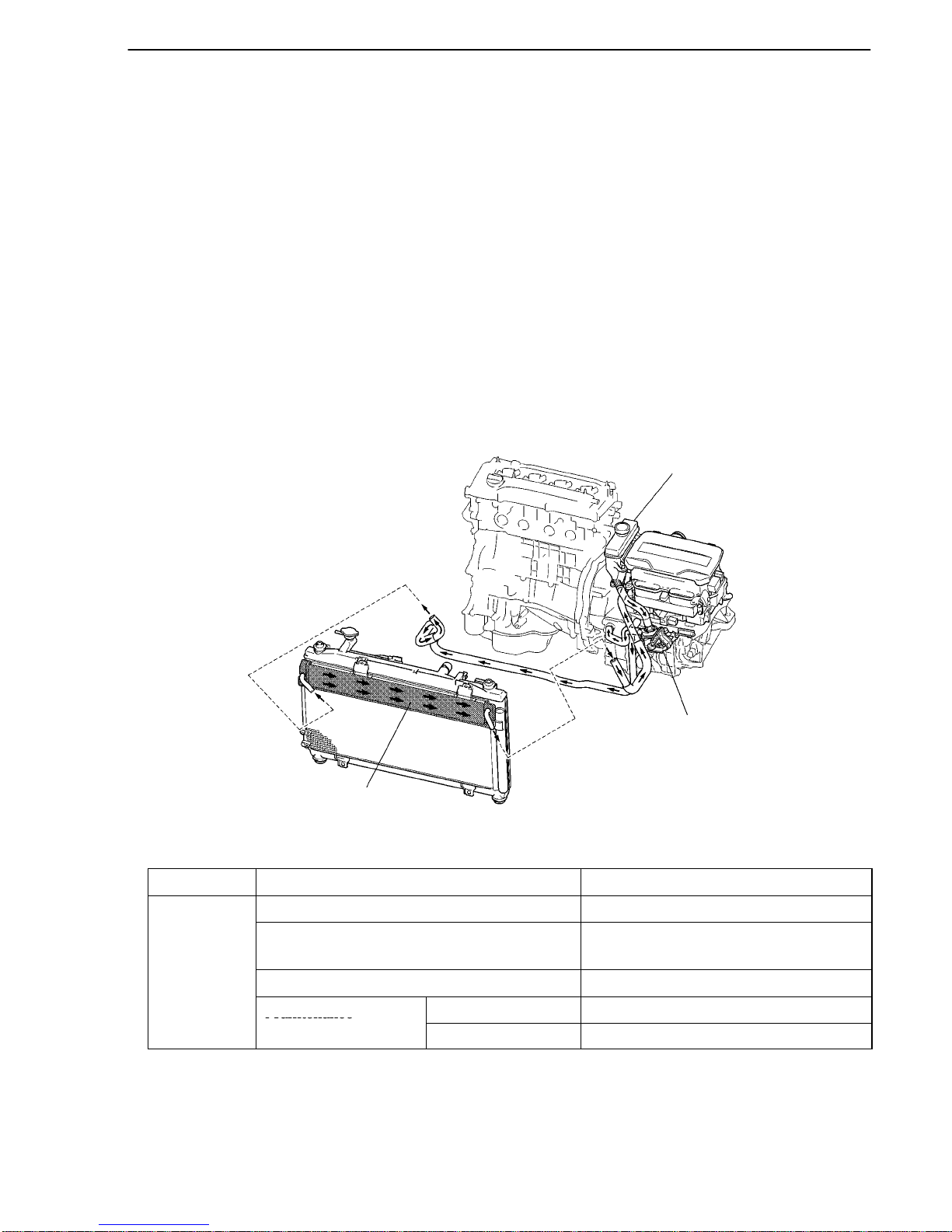
THS II (TOYOTA HYBRID SYSTEM II)
02HTH26TE
Reservoir Tank
Water Pump
Dedicated
Radiator
TH-27
MG (Motor Generator) ECU
The MG ECU is provided in the inverter assembly. In accordance with the signals received from the THS
ECU, the MG ECU controls the inverter and boost converter in order to drive MG1 or MG2 or cause them
to generate electricity.
The MG ECU transmits information that is required for vehicle control, such as the inverter output
amperage, inverter temperature, and any failure information, to the THS ECU. It receives information
that is required for controlling the motor generator, such as the required motive force and the motor
temperature, from the THS ECU.
3. Cooling System (for Inverter, MG1 and MG2)
A cooling system that is independent from the engine cooling system has been provided to cool the
inverter, MG1 and MG2.
This cooling system activates when the power supply status is switched to the READY ON state.
A radiator, which is exclusively used for the inverter, MG1 and MG2, has been provided above the
condenser (for the A / C). By integrating the independent inverter radiator, A / C condenser and engine
radiator, the layout has been made more compact.
Specifications
Water Pump Discharge Volume liter/min. 10 or above (65C (149F))
Capacity liters (US qts, Imp. qts) 2.9 (3.1, 2.6)
TOYOTA Genuine Super Long Life
Type
TOYOTA Genuine Super Long Life
Coolant (SLLC) or the equivalent*
Coolant
Color Pink
Maintenance
First Time 100,000 miles (160,000 km)
Maintenance
Intervals
Subsequent Every 50,000 miles (80,000 km)
*: Similar high quality ethylene glycol based non-silicate, non-amine, non-nitrite, and non-borate coolant
with long-life hybrid organic acid technology. (Coolant with hybrid organic acid technology consists of
a combination of low phosphates and organic acids.)
SLLC is pre-mixed (50% coolant and 50% deionized water for U.S.A. or 55% coolant and 45% deionized
water for Canada), so no dilution is needed when adding or replacing SLLC in the vehicle.
THS II (TOYOTA HYBRID SYSTEM II)
02HTH27TE
Rear Seat
Intake Duct
Cooling Fan
HV Battery
Unit
Exhaust Duct
TH-28
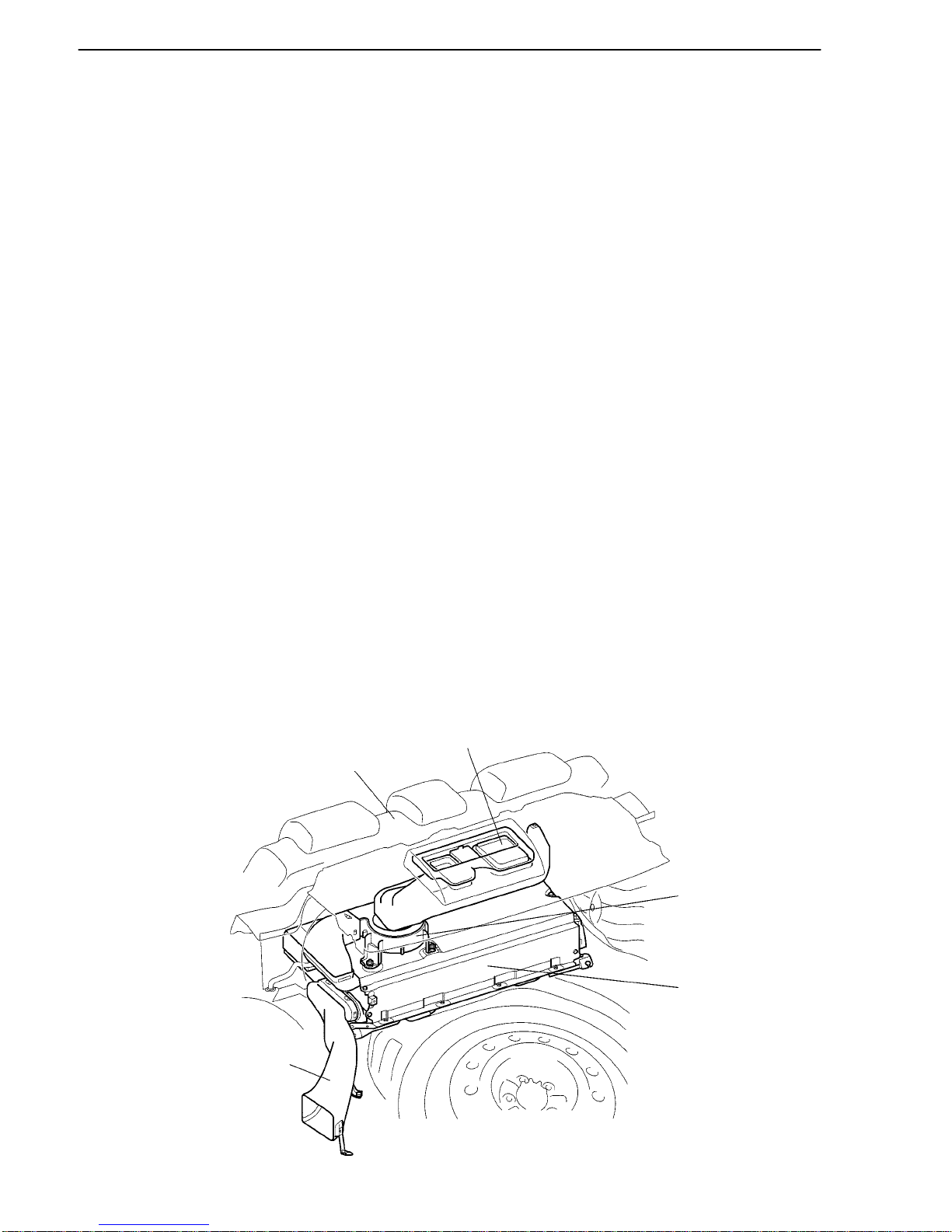
4. HV Battery
General
The ’07 Camry Hybrid model uses sealed nickel metal hydride (Ni-MH) HV batteries. The HV batteries
have a high power density, are lightweight and offer longevity to match the characteristics of the THS
II. Because the THS II effects charge/discharge control to maintain the HV batteries at a constant SOC
(state of charge) level while the vehicle is operating normally, it does not need to be recharged externally.
The HV batteries use nickel-plated, metal container type cells to realize enhanced cooling performance
and a compact construction. As a result, high power density, lightweight construction, and longevity have
been accomplished at high levels.
The HV battery unit consists of 34 separate batteries. The batteries each comprise 6 cells and they are
connected to each other in series through a bus bar module. The cells of the batteries are connected at
two locations in order to reduce the internal resistance and improve efficiency. The HV battery unit,
which has a total of 204 cells (6 cells x 34 batteries) and a nominal voltage of 244.8 V (1.2 V x 204 cells),
is located in the luggage compartment behind the rear seat.
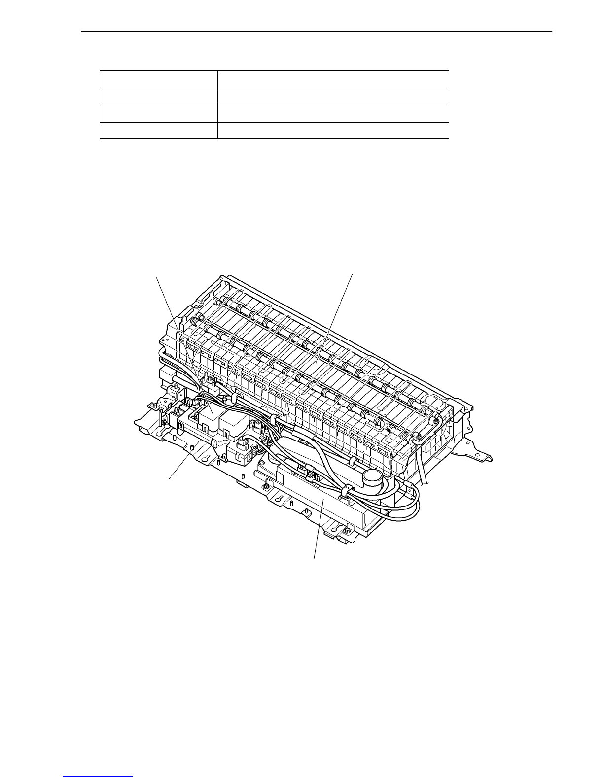
A junction block, battery smart unit and DC/DC converter are used. Integrated into the junction block
are an SMRG (System Main Relay Ground), SMRB (System Main Relay Battery) and a current sensor.
The battery smart unit monitors the HV battery. The DC/DC converter supplies power to the auxiliary
battery after decreasing the nominal voltage of DC 244.8 V supplied by the HV battery to DC 12 V. Power
to the lights, audio system, air conditioning system (except the electric inverter compressor) and ECUs
is supplied by the auxiliary battery.
The battery smart unit, junction block, and DC/DC converter are located in the battery front side carrier,
which is in the same housing as the HV battery unit. This realizes a compact package.
An air-cooling method, which uses a dedicated cooling fan to cool the HV battery with air from inside
the cabin, is employed. A dedicated cooling fan is also provided for the DC/DC converter. Thus, highly
efficient air-cooling has been achieved.
A service plug that shuts off the circuit is provided in the middle of the HV battery modules (between
No.18 and No.19 batteries). Before servicing any portion of the high-voltage circuit, be sure to remove
the service plug.
THS II (TOYOTA HYBRID SYSTEM II)
02HTH28Y
HV Battery
Junction Block
Battery Smart Unit
(Under the J/B)
DC-DC Converter
TH-29
Battery Specifications
Type Sealed Nickel Metal Hydride Battery
Cell Quantity 204 cells (6 cells x 34 Modules)
Cell Type Nickel Plated Metal Container
Nominal Voltage 244.8 V
Layout of Main Components
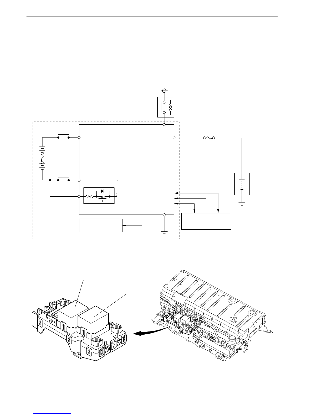
THS II (TOYOTA HYBRID SYSTEM II)
02HTH29Y
HV Battery Unit
HV
Battery
DC/DC Converter
SMRP
Battery
Smart Unit
IDH+DT
SMRP
VLO
NODD
GND
THS ECU
Auxiliary
Battery
DC/DC
AMD
IGCT
IGCT
Relay
02HTH30Y
SMRG
SMRB
Junction Block
TH-30
DC/DC Converter
The power source for auxiliary equipment of the vehicle such as the lights, audio system, and the air
conditioning system (except electric inverter compressor), as well as the ECUs, is based on a DC 12 V
system. Because the THS II generator outputs at nominal voltage of DC 244.8 V, the converter is used to
transform the voltage from DC 244.8 V to DC 12 V in order to recharge the auxiliary battery.
System Diagram
Junction Block
A junction block, in which an SMRG and SMRB are integrated, is used.
 Loading...