

Toyota 7FBE10-20 Repair Manual
FOREWORD
This manual covers the service procedures of the TOYOTA ELECTRIC
POWERED FORKLIFT 7FBE10 to 20 series.
Please use these manuals for providing quick, correct servicing of the corre-
sponding forklift models.
This manual deals with the above models as of February 2003. Please under-
stand that disagreement can take place between the descriptions in the man-
ual and actual vehicles due to change in design and specifications. Any
change or modifications thereafter will be informed by Toyota Industrial
Equipment Parts & Service News.

SECTION INDEX
NAME SECTION
GENERAL 0
BATTERY 1
CHARGER (OPT) 2
CONTROLLER 3
MULTI-DISPLAY FUNCTIONS 4
TROUBLESHOOTING 5
MOTOR 6
DRIVE UNIT & FRONT AXLE 7
REAR AXLE 8
STEERING 9
BRAKE 10
BODY & FRAME 11
MATERIAL HANDLING SYSTEM 12
MAST 13
CYLINDER 14
OIL PUMP 15
OIL CONTROL VALVE 16
SAS FUNCTIONS (OPT) 17
APPENDIX 18

0-1
GENERAL
Page Page
VEHICLE EXTERIOR VIEW........... 0-2
VEHICLE MODELS.......................... 0-3
FRAME NUMBER............................. 0-3
HOW TO USE THIS MANUAL ...... 0-4
EXPLANATION METHOD ................. 0-4
TERMINOLOGY................................. 0-5
ABBREVIATIONS .............................. 0-5
SI UNITS ............................................ 0-6
OPERATING TIPS ............................ 0-7
GENERAL INSTRUCTIONS .............. 0-7
JACK-UP POINT ............................... 0-8
HOISTING THE VEHICLE ................. 0-9
WIRE ROPE SUSPENSION ANGLE
LIST .............................................. 0-10
SAFE LOAD FOR EACH WIRE ROPE
SUSPENSION ANGLE ................. 0-10
HIGH PRESSURE HOSE FITTING
TIGHTENING TORQUE
RECOMMENDED LUBRICANT
QUANTITY AND TYPES
LUBRICATION CHART................. 0-19
PERIODIC MAINTENANCE......... 0-20
PERIODIC REPLACEMENT OF
PARTS AND LUBRICANTS
............. 0-17
........... 0-18
..... 0-25
0
1
2
3
4
5
6
7
8
9
10
11
MEMBER WEIGHTS........................ 0-11
TOWING THE VEHICLE .................. 0-11
ELECTRICAL PARTS
INSPECTION ................................ 0-12
NOTES ON SAS .............................. 0-14
STANDARD BOLT & NUT
TIGHTENING TORQUE
BOLT STRENGTH CLASS
IDENTIFICATION METHOD ......... 0-15
TIGHTENING TORQUE TABLE ...... 0-16
PRECOATED BOLTS ...................... 0-17
............. 0-15
12
13
14
15
16
17
18
0-2
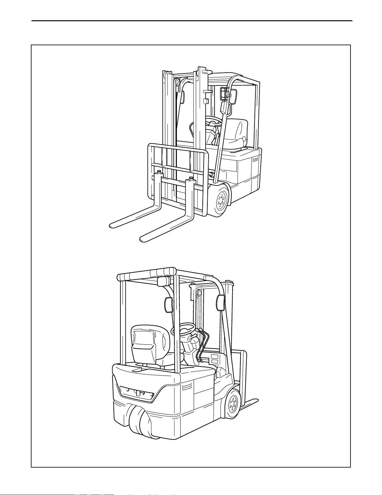
VEHICLE EXTERIOR VIEW
VEHICLE MODELS
Vehicle model code Payload (ton) Vehicle Model Control method Voltage (V)
10 1.0 7FBE10 AC microcomputer controller 48
13 1.25 7FBE13 ↑↑
15 1.5 7FBE15 ↑↑
18 1.75 7FBE18 ↑↑
0-3
0
20 2.0 7FBE20 ↑↑
FRAME NUMBER
Vehicle model Drive motor model Punching format Punching position
7FBE10
7FBE13-50011
7FBE13
7FBE15
7FBE18
7FBE20 7FBE20-50011
AR09
7FBE18-50011
Punching position
1
2
3
4
5
6
7
8
9
10
11
12
13
14
15
16
17
18
0-4
HOW TO USE THIS MANUAL
EXPLANATION METHOD
1. Operating procedure
(1) Operating procedures are described using either pattern A or pattern B.
Pattern A: Each step of the operation is explained with its own illustration.
Pattern B: The entire operation is indicated by step numbers in one illustration, followed by
cautions, notes, and point operations.
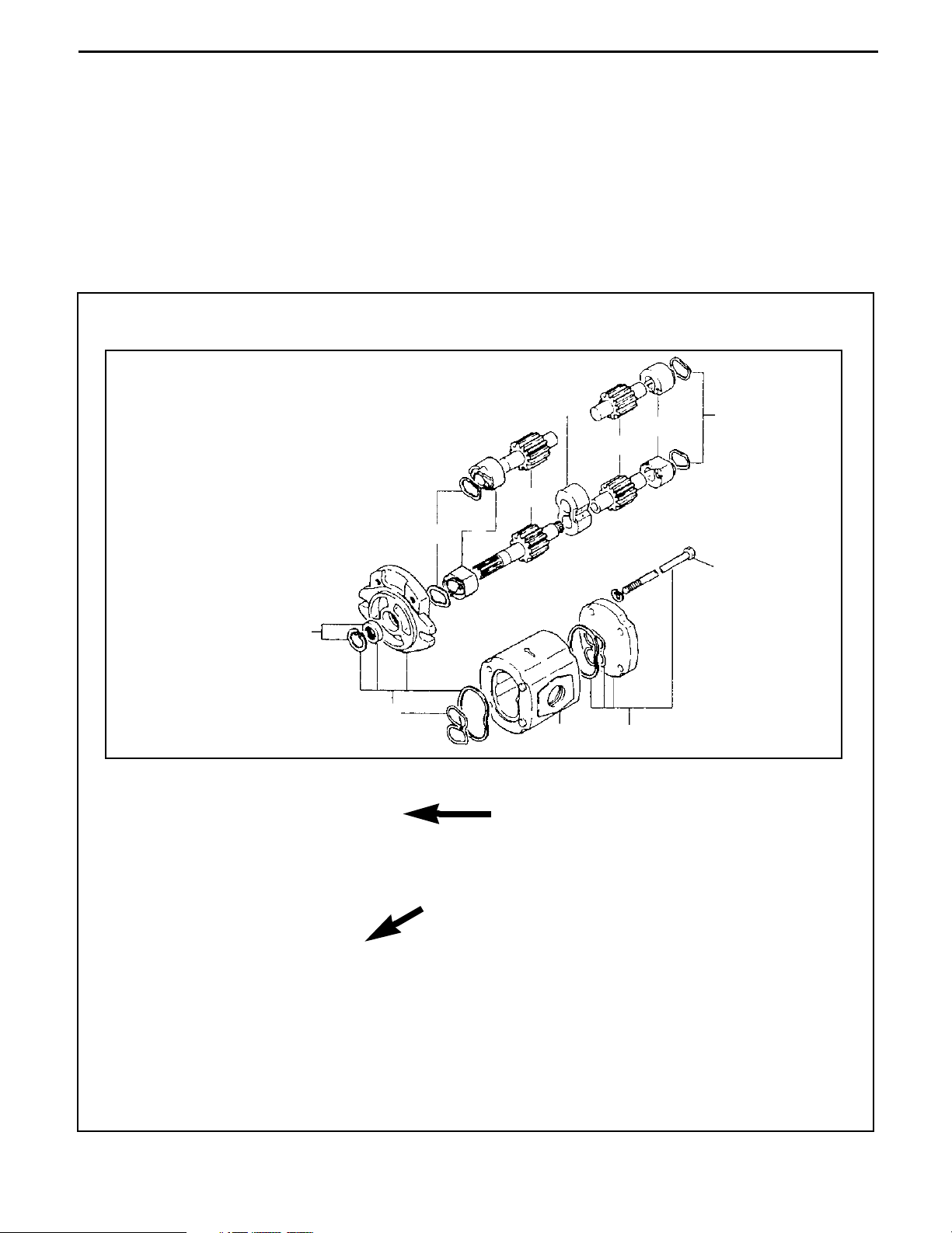
Example of pattern B
DISASSEMBLY · INSPECTION · REASSEMBLY
Tightening torque unit T=N·m(kg·m)[ft·lbf]
• Some step numbers may be
omitted in some illustrations.
8
Disassembly Procedure
1 Remove the cover. [Point 1]
2 Remove the bushing. [Point 2]
3 Remove the gear.
4
2
3
7
6
5
5
9
1
1
T = 46.1 to 48.1
(470 to 490)
[34.0 to 35.5]
Operation to be explained
Point Operations
[POINT 1]
Disassembly:
Make match marks before removing the pump cover
[POINT 2]
Inspection:
Measure the bushing inside diameter.
Limit 19.12 mm
Explanation of operation point with illustration

0-5
1. How to read component figures
(1) The component figures use the illustration in the parts
catalog for the vehicle model. Please refer to the catalog
to check the part name.
2. Matters omitted from this manual
(1) This manual omits descriptions of the following jobs, but perform them in actual operation:
(a) Cleaning and washing of removed parts as required
(b) Visual inspection (partially described)
TERMINOLOGY
CAUTION:
Important matters, negligence of which may cause accidents. Be sure to observe them.
NOTE:
Important items, negligence of which may cause accidents, or matters in operating procedure
which require special attention.
Standard: Value showing the allowable range in inspection or adjustment
Limit: The maximum or minimum value allowed in inspection or adjustment.
ABBREVIATIONS
(Example)
3201
Parts catalog
FIG number
0
1
2
3
4
5
6
Abbreviation Meaning Abbreviation Meaning
ASSY Assembly SAE
ATT Attachment SAS System of active stability
LH Left Hand SST Special Service Tool
L/ Less STD Standard
OPT Option T= Tightening Torque
O/S Oversize {{T Number of teeth ({{T)
PS system Power Steering U/S Undersize
RH Right Hand W/ With
Society of Automotive Engineers
(USA)
7
8
9
10
11
12
13
14
15
16
17
18
0-6
SI UNITS
Meaning of SI
This manual uses SI units. SI represents the International System of Units, which was established to unify
the various systems of units used in the past for smoother international technical communication.
New Units Adopted in SI
Item New unit
Conventional
Conversion rate*
unit
*2
2
N (newton) kgf 1 kgf = 9.80665 N
N·m kgf·cm 1 kgf·cm = 9.80665 N·m
2
Pa (pascal) kgf/cm
2
1 kgf/cm2 = 98.0665 kPa = 0.0980665 MPa
Force*
Torque
(Moment)
Pressure*
↑↑mmHg 1 mmHg = 0.133322 kPa
Revolving speed rpm rpm 1 rpm = 1 r/min
Spring con- N/mm kgf/mm 1 kgf/mm = 9.80665 N/mm
Volume l cc 1 cc = 1 ml
1
(1 [conventional unit] = X [SI
unit])
Power W PS system 1 PS = 0.735499 kW
Heat quantity W·h cal 1 kcal = 1.16279 W·h
Specific fuel g/W·h g/PS·h 1 g/PS·h = 1.3596 g/kW·h
<Reference>
* 1: X represents the value in SI units as converted from 1 [in conventional units], which can be
used as the rate for conversion between conventional and SI units.
* 2: In the past, kilogram [kg] representing mass was often used in place of weight kilogram [kgf],
which should be used as the unit of force.
Conversion between Conventional and SI Units
Equation for conversion
Value in SI unit = Conversion rate × Value in conventional unit Conversion rate: Figure corresponding
to X in the conversion rate column in
Value in conventional unit = Value in SI unit ÷ Conversion rate
the table above
When converting, change the unit of the value in conventional or SI units to the one in the
conversion rate column in the table above before calculation. For example, when converting 100 W
to the value in conventional unit PS, first change it to 0.1 kW and divide by the conversion rate
0.735499.

OPERATING TIPS
GENERAL INSTRUCTIONS
1. Skillful operation
(1) Prepare the tools, necessary measuring instruments (circuit tester, megohmmeter, oil pressure
gauge, etc.) and SSTs before starting operation.
(2) Check the cable color and wiring state before disconnecting any wiring.
(3) When overhauling functional parts, complicated sections or related mechanisms, arrange the parts
neatly to prevent confusion.
(4) When disassembling and inspecting a precision part such as the control valve, use clean tools and
operate in a clean location.
(5) Follow the specified procedures for disassembly, inspection and reassembly.
(6) Always replace gaskets, packing, O-rings, self-locking nuts and cotter pins with new ones each
time they are disassembled.
(7) Use genuine Toyota parts for replacement.
(8) Use specified bolts and nuts and observe the specified tightening torque when reassembling.
(Tighten to the medium value of the specified tightening torque range.) If no tightening torque is
specified, use the value given in the “standard tightening torque table”.
2. Protection of functional parts (battery operated vehicles)
(1) Before connecting the battery plug after vehicle inspection or maintenance, thoroughly check each
connector for any connection failure or imperfect connection.
Failure or imperfect connection of connectors related to controllers, especially, may damage
elements inside the controllers.
3. Defect status check
Do not start disassembly and/or replacement immediately, but first check that disassembly and/or
replacement is necessary for the defect.
4. Waste fluid disposal
Always use a proper container when draining waste fluid from the vehicle.
Careless discharge of oil, fuel, coolant, oil filter, battery or other harmful substance may adversely
affect human health and the environment. Always collect and sort well, and ask specialized companies
for appropriate disposal.
0-7
0-8
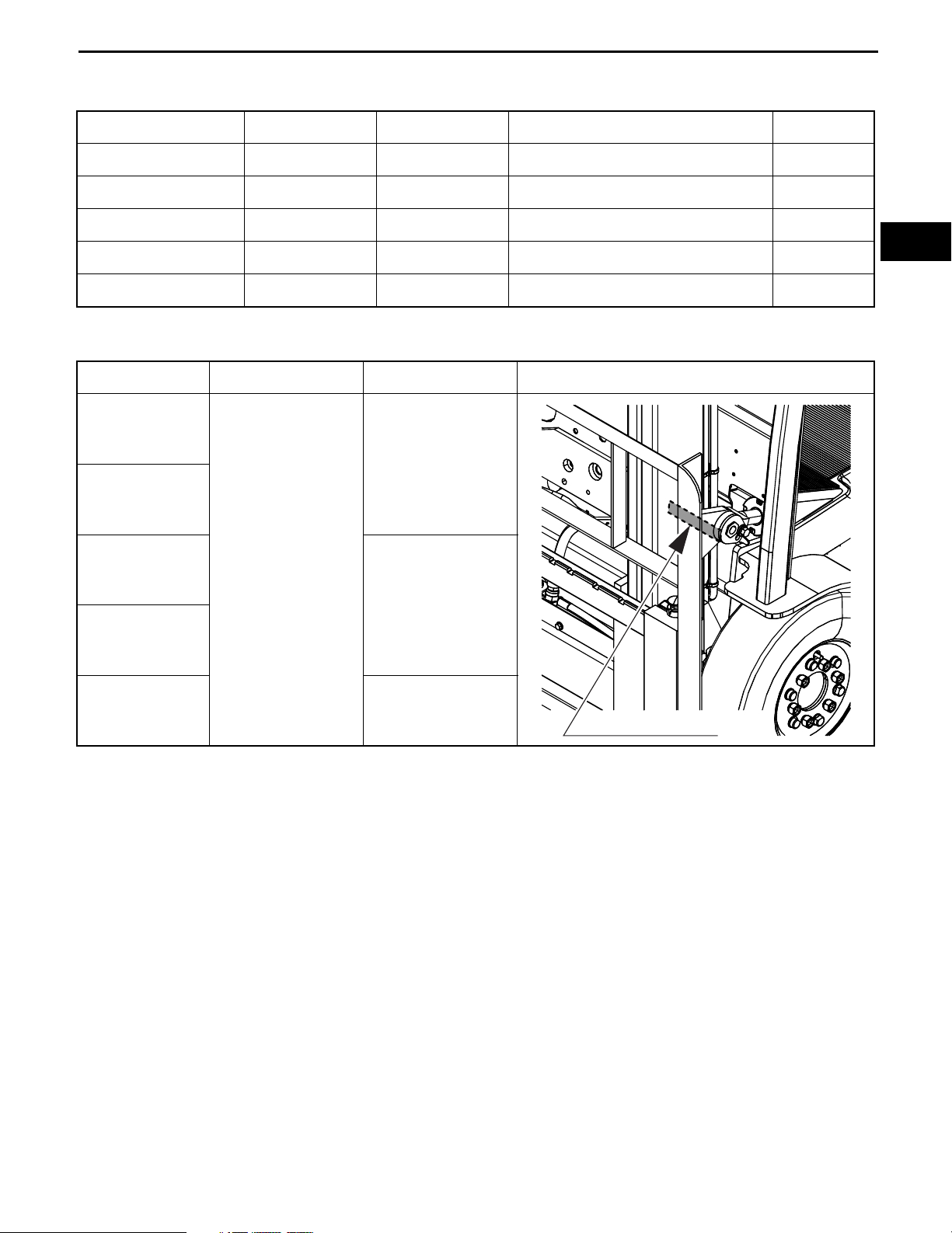
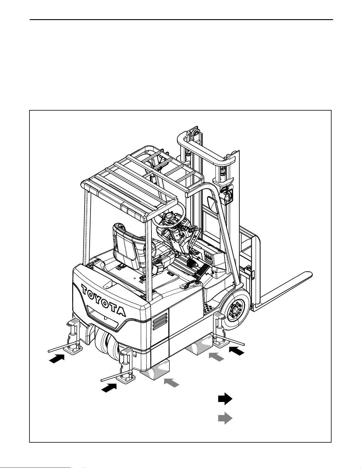
JACK-UP POINT
Always observe the following instructions when jacking up the vehicle:
• When the fork is loaded, unload it and park the vehicle on a flat surface. Be sure to avoid an
inclined or rough surface.
• Use a jack with ample capacity and jack up the vehicle at the specified jack-up point. Jacking up
at any other point is dangerous.
• Always support the load of jacked-up vehicle with wooden blocks at specified points.
Supporting the vehicle with the jack only is very dangerous.
• Never, under any circumstances, put any part of the body (including hands and feet) under the
jacked-up vehicle.
Jack-up point
Wooden block or stand
setting points
0-9
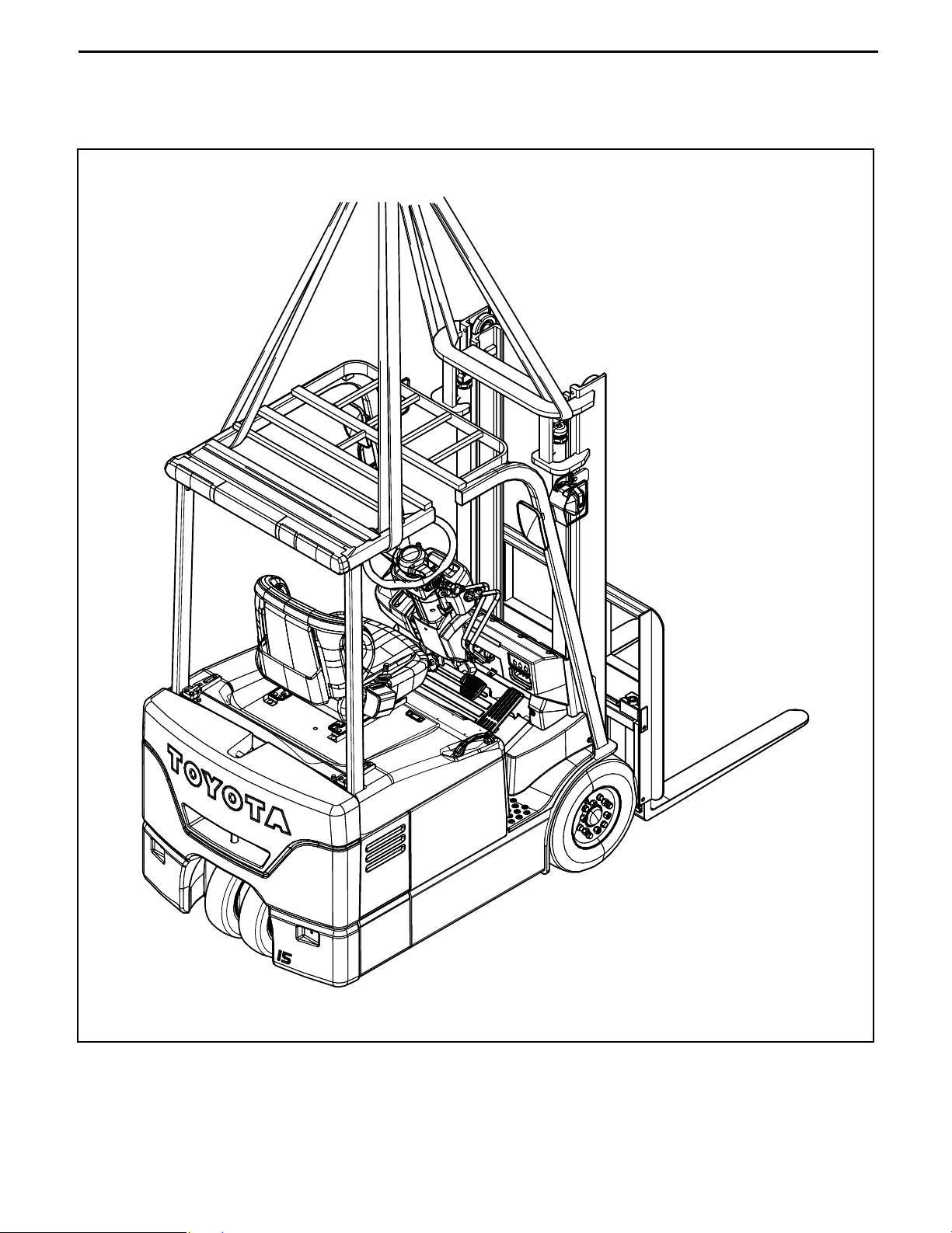
HOISTING THE VEHICLE
When hoisting the vehicle, always observe the specified hoist attachment section and method. Never hoist
by any other attachment section as it is very dangerous.
0-10
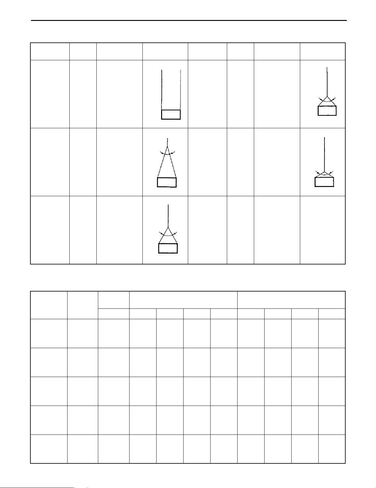
WIRE ROPE SUSPENSION ANGLE LIST
Suspension
Angle
0°
30°
60°
Tension Compression
1.00
time
1.04
time
1.16
time
0 time 90°
0.27 time 120°
0.58 time
Suspension
method
1tf
2t
30°
f
t
4
0
.
1
2t
60°
f
t
6
1
.
1
2t
Suspension
Angle
Tension Compression
1.41
time
2.00
time
1.00 time
1.73 time
Suspension
method
90°
f
t
1
4
.
2t
1
120°
f
t
2
2t
SAFE LOAD FOR EACH WIRE ROPE SUSPENSION ANGLE
Rope
diameter
6 mm
(0.24 in)
8 mm
(0.32 in)
10 mm
(0.4 in)
12.5 mm
(0.5 in)
14 mm
(0.56 in)
Cutting
load
21380
(2.18)
[4807]
31480
(3.21)
[7078]
49230
(5.02)
[11690]
76880
(7.84)
[17387]
96400
(9.83)
[21675]
Single-
rope
0° 0° 30° 60° 90° 0° 30° 60° 90°
3040
(0.31)
[683.6]
4410
(0.45)
[992.3]
6960
(0.71)
[1565.6]
10980
(1.12)
[2469.5]
13730
(1.4)
[3087]
Two-rope suspension four-rope suspension
6080
(0.62)
[1367]
8830
(0.9)
[1985]
14020
(1.43)
[3153]
21570
(2.2)
[4851]
27460
(2.8)
[6174]
5880
(0.6)
[1323]
8530
(0.87)
[1918]
13440
(1.37)
[3021]
21280
(2.1)
[4631]
26480
(2.7)
[5954]
5200
(0.53)
[1169]
7650
(0.78)
[1720]
11770
(1.2)
[2646]
18630
(1.9)
[4190]
23540
(2.4)
[5292]
4310
(0.44)
[970]
6280
(0.64)
[1411]
9810
(1.0)
[2205]
14710
(1.5)
[3308]
18630
(1.9)
[4190]
12160
(1.24)
[2734]
17650
(1.8)
[3969]
27460
(2.8)
[6174]
43150
(4.4)
[9702]
54920
(5.6)
[12348]
11770
(1.2)
[2646]
17060
(1.74)
[3937]
26480
(2.7)
[5954]
41190
(4.2)
[9261]
52960
(5.4)
[11907]
Unit: N (tf) [lbf]
10400
(1.06)
2337
15300
(1.56)
[3440]
23540
(2.4)
[5292]
37270
(3.8)
[8379]
47070
(4.8)
[10584]
8630
(0.88)
[1940]
12550
(1.28)
[2322]
19610
(2.0)
[4410]
29420
(3.0)
[6615]
37270
(3.8)
[8379]
MEMBER WEIGHTS
Unit: kg (lbs)
Member Vehicle model Weight
BATTERY ASSY See P1-2
Drive motor ASSY All Models Approx. 37 (82)
Pump motor ASSY All Models Approx. 31 (68)
Front axle ASSY W/ drive motor ASSY All Models Approx. 122 (269)
Rear axle ASSY W/ rear axle cylinder ASSY All Models Approx. 45 (99)
7FBE10 Approx. 405 (893)
7FBE13 Approx. 598 (1319)
Counterweight
7FBE15 Approx. 697 (1537)
7FBE18 Approx. 853 (1881)
7FBE20 Approx. 1040 (2293)
0-11
Mast ASSY W/ lift bracket (W/ lift cylinder, L/ fork,
Lifting height 3000mm, V mast)
Vehicle weight
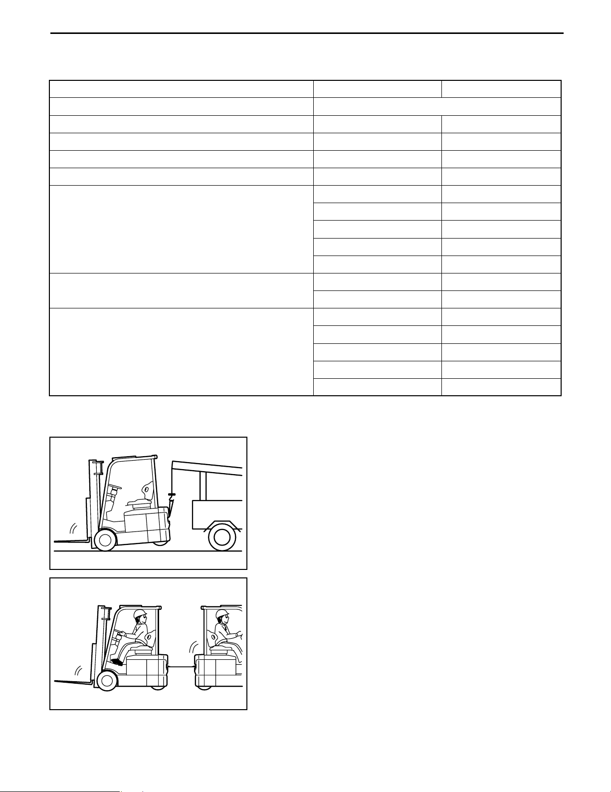
TOWING THE VEHICLE
Note the cautions below when towing the vehicle.
1. Lift the rear wheels for towing
2. The traveling speed when towing must not exceed the
3. Before starting towing, always set the key switch to OFF
4. Before towing, either remove the fork or take action to
7FBE10 to 7FBE18 330 (730)
7FBE20 400 (880)
7FBE10 2225 (4906)
7FBE13 2425 (5347)
7FBE15 2685 (5920)
7FBE18 2840 (6262)
7FBE20 3155 (6957)
maximum traveling speed of the forklift.
and the direction switch to the neutral position.
prevent the fork from coming into contact with the
ground due to bouncing.
0-12
ELECTRICAL PARTS INSPECTION
1. Always disconnect the battery plug before inspecting or servicing electrical parts.
2. Pay sufficient attention when handling electronic parts.
(1) Never subject electronic parts, such as computers
and relays, to impact.
(2) Never expose electronic parts to high temperature or
moisture.
(3) Do not touch connector terminals, as they may be
deformed or damaged due to static electricity.
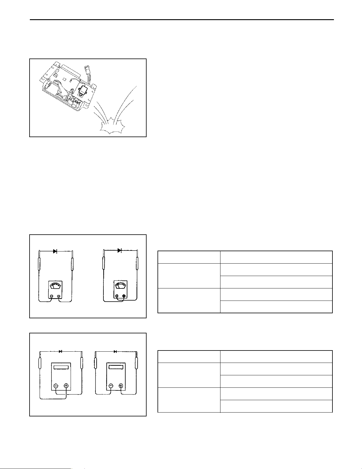
3. Use a circuit tester that matches the object and purpose of measurement.
Analog type: This type is convenient for observing movement during operation and the operating
condition. Measured value is only a reference
Digital type: A fairly accurate reading is possible. However, it is difficult to observe operation or
movement.
(1) Difference between results of measurement with analog and digital types
∗ The results of measurements using the analog type and the digital type may be different.
Differences between the polarities of the analog type and the digital type are described below.
1) Analog circuit tester
Forward
Reverse
Example of measurement result
Tester range: kΩ range
Analog type
Continuity
Forward
11 kΩ
No continuity
Reverse
∞
2) Digital circuit tester
Example of measurement result
Forward
Reverse
Tester range: 2 MΩ range
Digital type
No continuity
Forward
1
Reverse
Continuity
2 MΩ
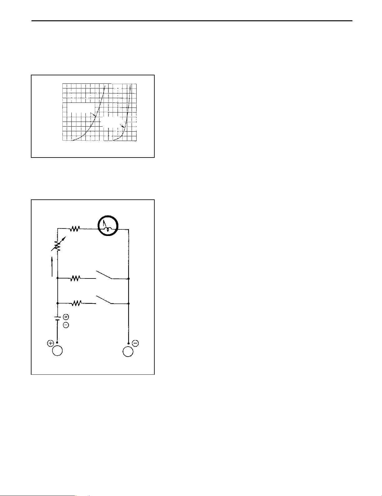
(2) Difference in result of measurement with a circuit tester
The circuit tester power supply voltage depends on the tester type. 1.5 V, 3.0 V or 6.0 V is used.
The resistance of a semiconductor, such as a diode, varies with the circuit tester power supply
voltage.
The diode characteristics are shown in the figure below.
0-13
(mA)
Forward current
6
5
4
Germanium
diode
3
2
1
0
0.1 0.2 0.3 0.4 0.5 0.6 0.7 0.8
Silicon
diode
(V)Forward voltage
The resistance values of the same semiconductor measured
with two types of circuit testers having different power supply
voltages are different.
This manual describes the results of measurement with a
circuit tester whose power supply voltage is 3.0 V.
(3) Difference in measurement result by measurement range (analog type)
In the analog type circuit tester, changing the measurement range switches over the internal circuit
to vary the circuit resistance. Even when the same diode is measured, the measurement result
varies with the measurement range.
Always use the range described in the repair manual for
measurement.
Resistor Meter
0 Ω
Variable resistor
Current flow
Resistor
Range:×10
Resistor
Range:×1
Power source: 1.5V
Red
(SW1)
Black

0-14
NOTES ON SAS
1. For the explanations of SAS functions and operation, also see “New Model Feature 7FBE10 to 20 Pub.
No.PE314”.
2. See page 17-6 FOR REPAIR WORK of this repair manual before servicing.
3. If repair or replacement is performed in any section of the vehicle that relates to SAS function, perform
necessary matching to ensure proper SAS function (see page 4-47).
4. always be sure to operate the vehicle carefully. Be aware of the difference in control features between
with and without SAS.
5. Many precision valves are used in the SAS oil control valves. When disassembling or replacing
hydraulic parts (valves, piping, etc.), be sure to clean the parts before installation. Periodic change of
the hydraulic oil is also very important.
6. As the vehicle is equipped with high-precision electronic devices, modification of electrical parts may
cause vehicle failure. Be sure to use genuine Toyota parts for replacement and installation of the
electrical parts (auxiliary equipment, optional parts, etc.).
0-15
STANDARD BOLT & NUT TIGHTENING TORQUE
Tightening torque of standard bolts and nuts are not indicated throughout the manual.
Use the charts and table below to judge the standard tightening torque.
1. Find the class of the bolt strength on the table below and then find the bolt tightening torque on the
tightening torque table.
2. The nut tightening torque can be judged from its corresponding bolt type.
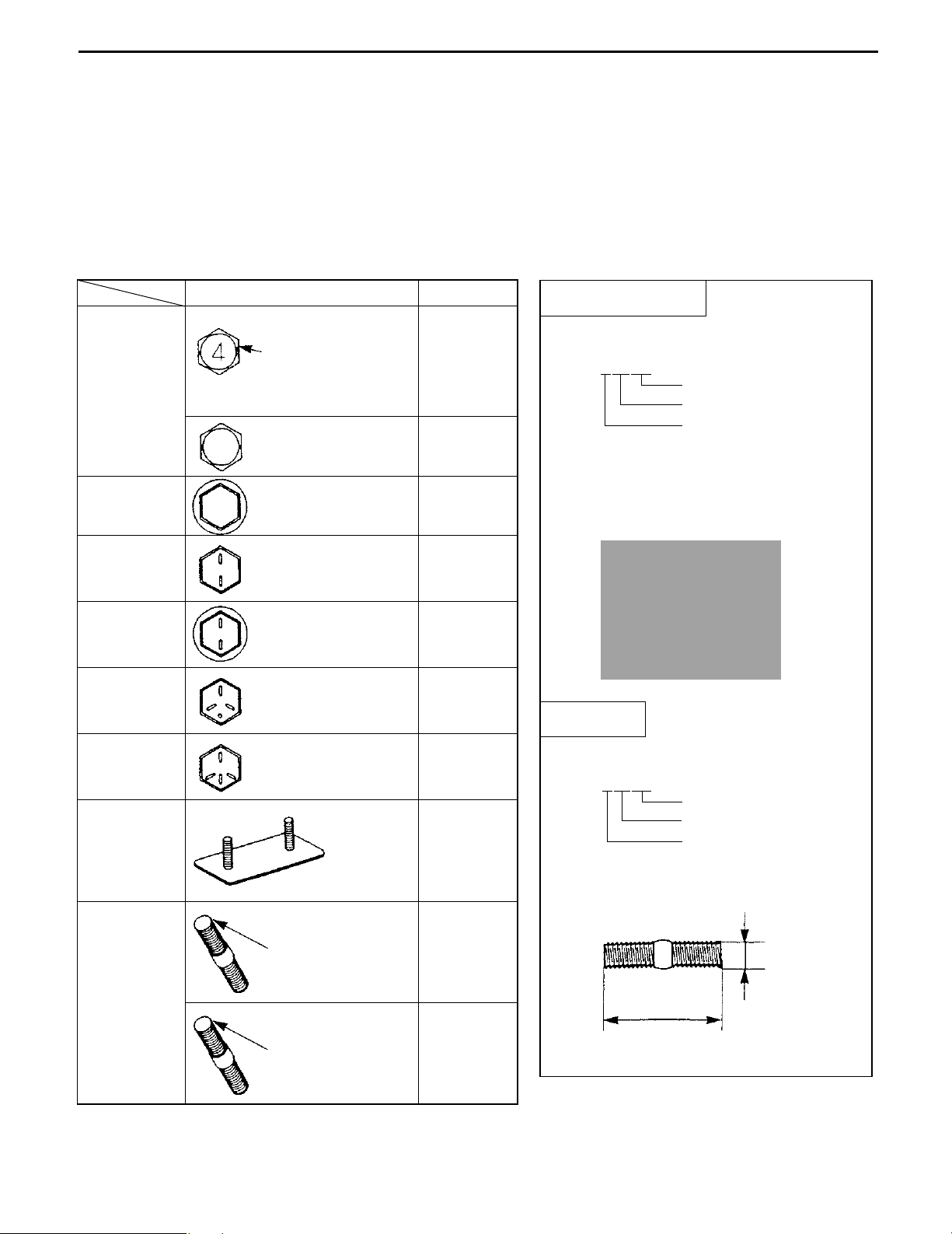
BOLT STRENGTH CLASS IDENTIFICATION METHOD
Identification by bolt shape Identification by part No.
Shape and class Class
Hexagon
head bolt
Hexagon
bolt
(standard)
Hexagon
flange bolt
Hexagon
head bolt
(standard)
Hexagon
flange bolt
Bolt with raised
or etched
numeral on head
No mark 4T
No mark 4T
Bolt with two
raised lines on
head
Bolt with two
raised lines on
4 = 4T
5 = 5T
6 = 6T
7 = 7T
8 = 8T
5T
6T
head
Hexagon
head bolt
(standard)
Hexagon
head bolt
(standard)
Bolt with three
raised lines on
head
Bolt with four
raised lines on
head
7T
8T
Welded bolt 4T
Hexagon head bolt
Part No.
91611-40625
Length (mm)
Nominal diameter (mm)
Class
Nominal diameter
Length
Stud bolt
Part No.
92132-40614
Length (mm)
Nominal diameter (mm)
Class
Stud bolt
No mark 4T
2 mm groove(s)
on one/both
6T
edge(s)
Nominal diameter
Length

0-16
TIGHTENING TORQUE TABLE
Standard tightening torque
Class
4T
5T
6T
Nominal
diameter
mm
6
8
10
12
14
16
6
8
10
12
14
16
6
8
10
12
14
16
Pitch
1.0
1.25
1.25
1.25
1.5
1.5
1.0
1.25
1.25
1.25
1.5
1.5
1.0
1.25
1.25
1.25
1.5
1.5
mm
Hexagon
head bolt
N·m kgf·cm ft·lbf N·m kgf·cm ft·lbf
5.4
13
25
47
75
113
6.4
16
32
59
91
137
7.8
19
38
72
110
170
55
130
260
480
760
1150
65
160
330
600
930
1400
80
195
400
730
1100
1750
48in·lbf
9
19
35
55
83
56in·lbf
12
24
43
67
101
69in·lbf
14
29
53
80
127
Hexagon
flange bolt
5.9
14
28
53
83
7.5
18
36
65
100
157
8.8
21
43
79
123
191
60
145
290
540
850
75
175
360
670
1050
1600
90
215
440
810
1250
1950
52in·lbf
65in·lbf
78in·lbf
10
21
39
61
13
26
48
76
116
16
32
59
90
141
7T
8T
6
8
10
12
14
16
6
8
10
12
14
16
1.0
1.25
1.25
1.25
1.5
1.5
1.0
1.25
1.25
1.25
1.5
1.5
11
25
52
95
147
226
12
29
61
108
172
265
110
260
530
970
1500
2300
125
300
620
1100
1750
2700
8
19
38
70
108
166
9
22
45
80
127
195
12
28
58
103
167
14
32
68
123
196
299
120
290
590
1050
1700
145
330
690
1250
2000
3050
9
21
43
76
123
9
24
50
90
145
221
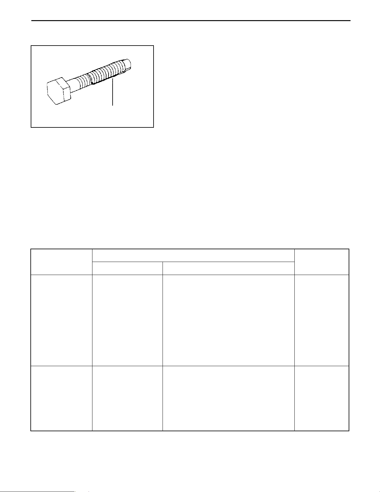
PRECOATED BOLTS
1. Do not replace or restore a precoated bolt as it is in the
following cases:
(1) After it has been removed.
(2) When it has been moved by tightness check, etc.
(loosened or tightened)
NOTE:
For torque check, tighten the bolt at the lower limit of the
Seal lock agent
allowable tightening torque range; if the bolt moves,
retighten it according to the steps below.
2. How to reuse precoated bolts
(1) Wash the bolt and threaded hole.
(The threaded hole must be washed even when
replacing the bolt with a new one)
(2) Completely dry the washed parts by blowing with air.
(3) Apply a specified seal lock agent to the threaded
portion of the bolt.
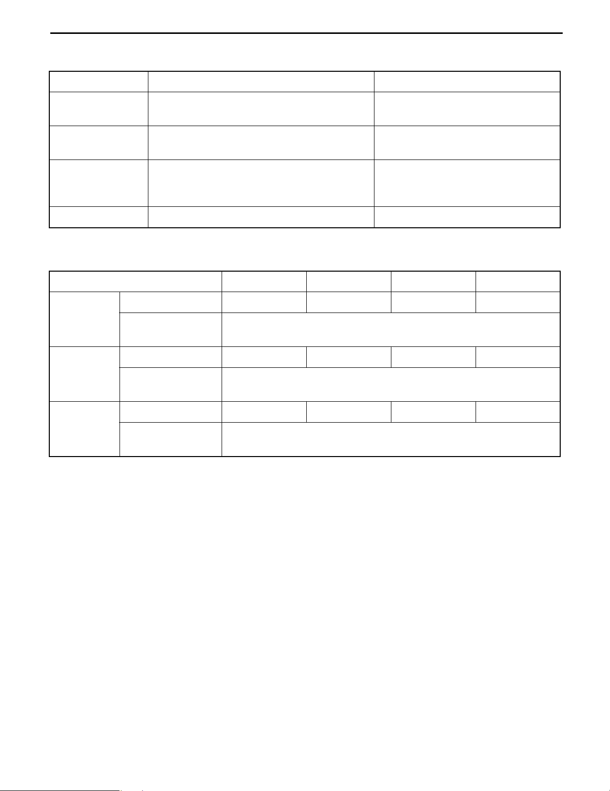
HIGH PRESSURE HOSE FITTING TIGHTENING TORQUE
0-17
1. When connecting a high pressure hose, wipe the hose fitting and corresponding nipple contact
surfaces with a clean cloth to remove foreign matter and dirt. Also check that there are no dents or
other damage on the contact surfaces before installation.
2. When connecting the high pressure hose, hold the hose to align the fitting with the nipple and tighten
the fitting.
3. The maximum tightening torque must not exceed twice the standard tightening torque.
Nominal diameter
of screw
7/16-20UNF 25 (50) [18.1] 24 to 26 (240 to 270) [17.4 to 19.5] 6 (0.24)
9/16-18UNF 49 (500) [36.2] 47 to 52 (480 to 530) [34.7 to 38.3] 9 (0.35)
3/4-16UNF 59 (600) [43.4] 56 to 62 (570 to 630) [41.2 to 45.6] 12 (0.47)
7/8-14UNF 59 (600) [43.4] 56 to 62 (570 to 630) [41.2 to 45.6] 12 (0.47)
7/8-14UNF 78 (800) [57.9] 74 to 82 (740 to 840) [53.5 to 60.8] 15 (0.59)
1•1/16-12UNF 118 (1200) [86.8] 112 to 123 (1140 to 1250) [82.5 to 90.4] 19 (0.75)
1•5/16-12UNF 137 (1400) [101.3] 130 to 144 (1330 to 1470) [96.2 to 106.4] 25 (0.98)
PF1/4 25 (250) [18.1] 24 to 26 (240 to 270) [17.4 to 19.5] 6 (0.24)
Tightening torque standard N·m (kgf·cm) [ft·lbf] Inside diameter
Standard Tightening range
of hose
mm (in)
PF3/8 49 (500) [36.2] 47 to 52 (480 to 530) [34.7 to 38.3] 9 (0.35)
PF1/2 59 (600) [43.4] 56 to 62 (570 to 630) [41.2 to 45.6] 12 (0.47)
PF3/4 118 (1200) [86.8] 112 to 123 (1140 to 1250) [82.5 to 90.4] 19 (0.75)
PF1 137 (1400) [101.3] 130 to 144 (1330 to 1470) [96.2 to 106.4] 25 (0.98)
0-18
RECOMMENDED LUBRICANT QUANTITY AND TYPES
Application Type Capacity
Drive unit
Hydraulic oil STD: Castle hydraulic oil (ISO VG32)
Chassis parts
Battery Distilled water Appropriate amount
Hydraulic oil level by lifting height
Castle hypoid gear oil W
(API GL-4, SAE 75W-80)
Cold storage vehicle: Mobil Aero HFE
MP grease
Chassis grease special
Esso beacon 325
Approx. 0.4 l (0.11 US gal)
(Until purring out from the filler port)
See “Hydraulic oil level by lifting
height” below
Appropriate amount
Unit:l
Lifting height V mast SV mast FV Mast FSV Mast
Capacity 14 (3.70) 14 (3.70) 17 (4.49)
To 3000mm
(118 in)
To 4000mm
(157.5 in)
Hydraulic oil level
in the tank
Capacity 15 (3.96) 15 (3.96) 19 (5.01) 16 (4.22)
Hydraulic oil level
in the tank
12.4 (3.27)
14.2 (3.75)
l (US gal)
l l
To 6000mm
(236 in)
Capacity 18 (4.75) 19 (5.01)
Hydraulic oil level
in the tank
17.2 (4.54)
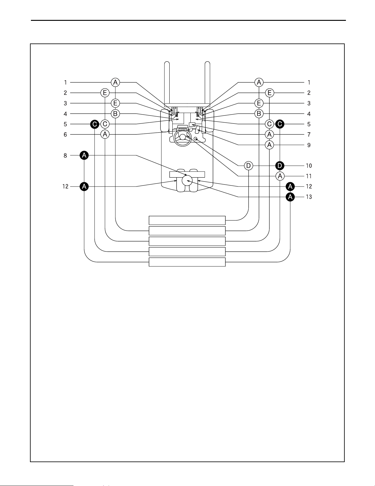
LUBRICATION CHART
0-19
I
II
III
IV
V
{: Inspection and addition I. Inspection every 8 hours (daily)
z: Replacement II. Inspection every 40 hours (weekly)
A: MP grease III. Inspection every 170 hours (monthly)
B: Motor oil IV. Inspection every 1000 hours (6 monthly)
C: Gear oil (SAE 75W-80) V. Inspection 2000 hours (annual)
D: Hydraulic oil (ISO VG32)
E: Chassis grease special
1. Mast strip 8. Steering rack and pinion gear
2. Tilt cylinder front pin 9. Accelerator link
3. Mast support bushing 10. Oil tank
4. Lift chain 11. Tilt steering lock device
5. Drive unit 12. Rear wheel bearing
6. Brake link 13. Rear axle bearing
7. Oil control valve lever pin
0-20
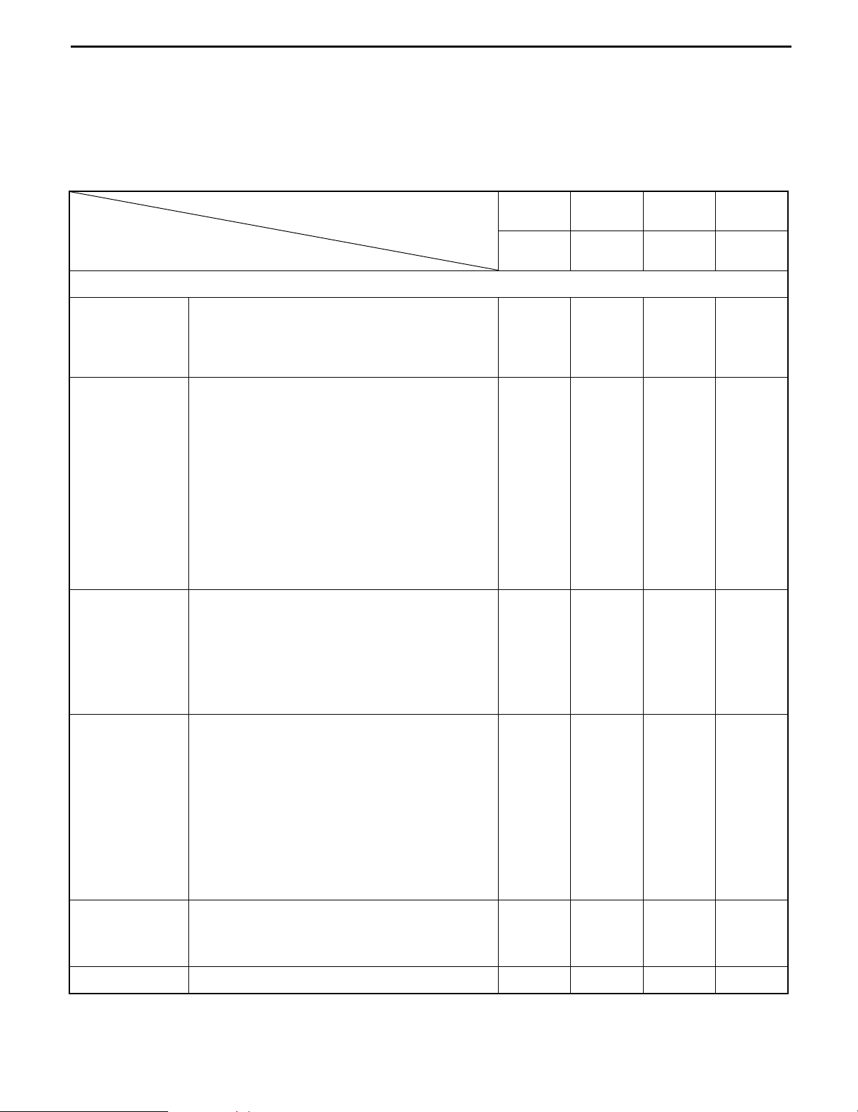
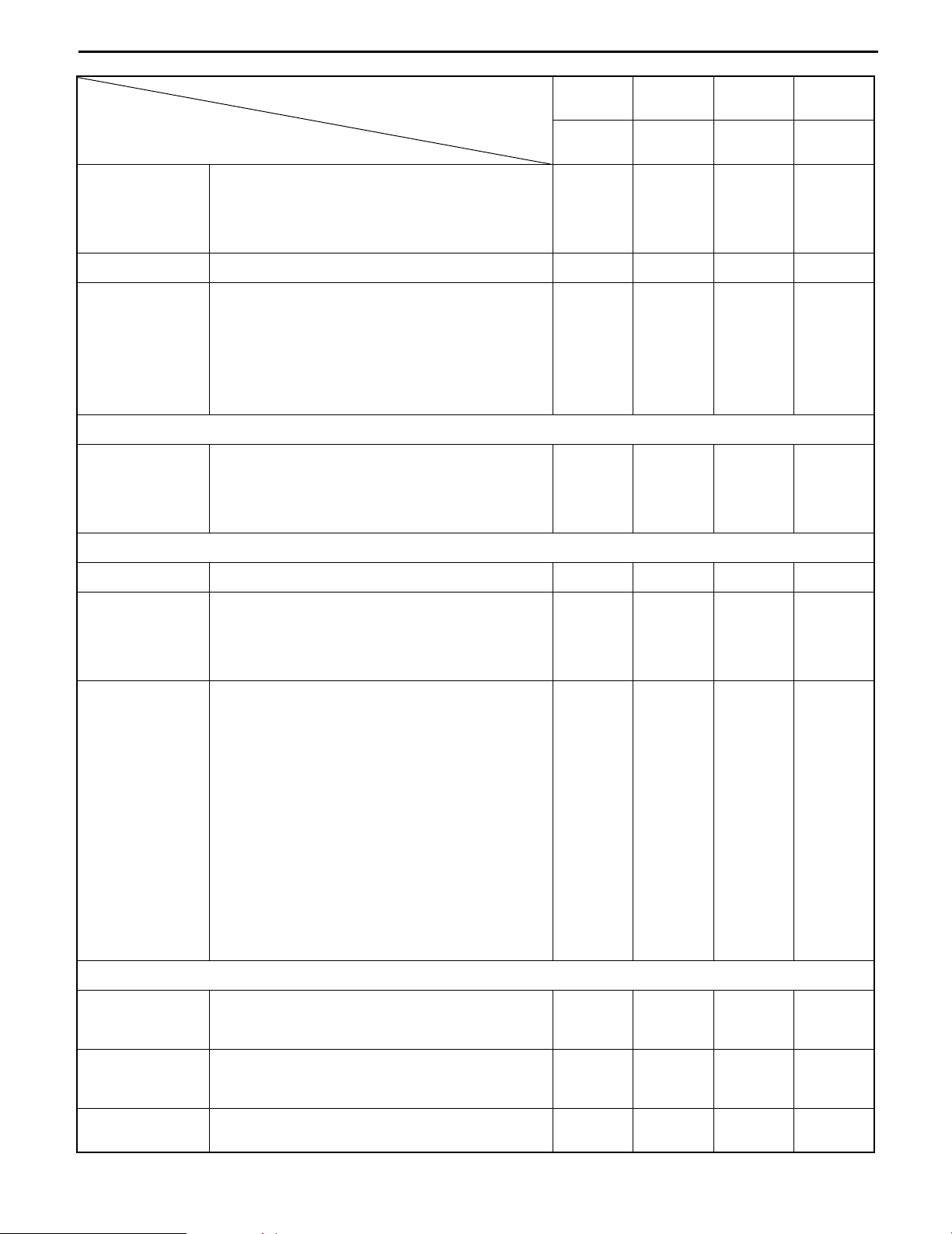
PERIODIC MAINTENANCE
INSPECTION METHOD
I: Inspection · Repair or Replacement if required
M: Measurement · Repair or Adjustment if required
T: Retightening C: Cleaning L: Lubrication
*:
For new vehicle *1: Flaw detector
Item
ELECTRICAL SYSTEM
Rotation sound abnormality I ←←←
Motor
Battery
Looseness in the connecting parts T ←←←
Insulation resistance M ←←
Charging level (Display) I ←←←
Electrolyte level I ←←←
Electrolyte specific gravity M ←←←
Looseness in the connecting parts I ←←←
Abnormality in the upper portion of the
battery and/or the case
Insulation resistance M ←←
Voltage measurement of each battery cell
after charging
Timer function (Timer test) I ←←←
Inspection timing
Every
month
Every
170 hours
I ←←←
Every 3
months
Every
500 hours
Every 6
months
Every
1000 hours
Every 12
months
Every
2000 hours
M
Looseness in the connecting parts T ←←←
Charger
Magnet switch
Micro switch
Direction lever Operating condition, damage I ←←←
HVR function voltage measurement M
Operating condition of the magnetic switch,
contact contamination, roughness
Contact looseness, damage, abrasion I ←←←
Operating condition, contamination and
abrasion of the auxiliary contact
Mounting condition of the arc shooter I
Operating condition and timing I
Looseness of the coil installation locations I
Mounting condition and looseness of the
main circuit lead wire
Operating condition and timing I ←←←
Damage and looseness of installation
locations
I ←←←
I ←←←
I
I
0-21
Inspection timing
Item
Operating condition I ←←←
Controller
Fuses Looseness of the installation locations I ←←←
Wiring
(incl. charging
cable)
POWER TRANSMISSION SYSTEM
Drive unit
Interior contamination, damage C ←←←
Motor input voltage M
Harness deterioration, damage and
looseness of the clamp
Looseness of the connections, taping
condition
Connecting condition and damage of the
battery connector
Oil leak I ←←←
Oil level I ←←←
Bolt or nut looseness T
Every
month
Every
170 hours
I ←←←
I ←←←
I ←←←
Every 3
months
Every
500 hours
Every 6
months
Every
1000 hours
Every 12
months
Every
2000 hours
DRIVE SYSTEM
Front axle Damage and deformation I
Damage and deformation I
Rear axle
Wheels
STEERING SYSTEM
Looseness of rear axle bearing I
Abnormal noise of rear axle bearing I
Tire pressure M ←←←
Tire crack, damage and abnormal wear I ←←←
Tire tread depth M ←←←
Metal piece, stone and other foreign matter
on tire
Loosening of wheel nut and bolt T ←←←
Rim, side ring and disc wheel damage I ←←←
Looseness and abnormal noise of front
wheel bearing
Looseness and abnormal noise of rear
wheel bearing
I ←←←
I ←←←
I ←←←
Steering wheel
Steering valve
Wheels for
steering
Play, loosening, looseness I ←←←
Function I ←←←
Oil leak I ←←←
Looseness of the installation locations T ←←←
Turning angle to left and right I

0-22
Item
Oil leak I ←←←
Power steering
Looseness of the installation locations I ←←←
Damage of power steering hose I
BRAKING SYSTEM
Reserve M ←←←
Brake pedal
Braking performance I ←←←
Operating force and pull margin I ←←←
Parking brake
Braking performance I ←←←
Looseness and damage I ←←←
Rod and cable
Operating condition I ←←←
Clearance between disc and pad M ←←←
Wear of sliding portion and pad I
Disc wear and damage I
Disc brake
Looseness of the disc installation locations I
Inspection timing
Every
month
Every
170 hours
Every 3
months
Every
500 hours
Every 6
months
Every
1000 hours
Every 12
months
Every
2000 hours
Operating condition I
Return spring fatigue I
MATERIAL HANDLING SYSTEM
Damage or wear of fork or stopper pin I ←←←
Fork
Fork deformation and wear I ←←←
Cracks at fork root and welded part of tooth I
Deformation and damage of each part and
crack at welded part
Wear and damage of roller I ←←←
Mast and
lift bracket
Mast and lift bracket looseness I ←←←
Wear and damage of mast support bushing I
Wear and damage of roller pin I
Wear and damage of mast strip I ←←←
Chain lubrication I ←←←
Deformation, damage and slackness of
Chain and
chain wheel
chain
Abnormality of chain anchor bolt I ←←←
*1
I ←←←
I ←←←
Various
attachments
Wear, damage and revolution of chain
wheel
Abnormality and installation condition of
each part
I ←←←
I ←←←

0-23
Inspection timing
Item
HYDRAULIC SYSTEM
Looseness, deformation and damage of rod
and rod end
Cylinder operation I ←←←
Natural drop and natural forward tilt M ←←←
Oil leak and damage I ←←←
Cylinder
Oil pump Oil leak and abnormal sound I ←←←
Hydraulic oil
tank
Wear and damage of pin and cylinder
bearing
Loosening and damage of cylinder
mounting
Lifting speed M ←←←
Uneven movement I ←←←
Oil level and contamination I ←←←
Oil leak I ←←←
Tank and oil strainer cleaning C ←
Every
month
Every
170 hours
I ←←←
I ←←←
T ←←←
Every 3
months
Every
500 hours
Every 6
months
Every
1000 hours
Every 12
months
Every
2000 hours
Hydraulic oil
filter
Control lever
Oil control
valve
Hydraulic hose
and piping
SAFETY DEVICES, ETC.
Head guard
and backrest
Lighting system Function and installation condition I ←←←
Direction
indicator
Horn Function and installation condition I ←←←
Filter clogging C
Loose linkage I ←←←
Operation I ←←←
Oil leak I ←←←
Safety valve function I ←←←
Relief pressure measurement M
Oil leakage, deformation and damage I ←←←
Looseness T ←←←
Looseness of the installation locations T ←←←
Deformation, crack and damage I ←←←
Crack at welded portion I ←←←
Function and installation condition I ←←←
Backup buzzer Function and installation condition I ←←←
Rear view
mirror
Rear reflection status I ←←←
Dirt, damage I ←←←

0-24
Inspection timing
Item
Instruments Operation I ←←←
Loosening and damage of mounting I ←←←
Seat
Body
SAS
Seatbelt damage and function I ←←←
Deadman seat operation I ←←←
Damage and cracks in frame, cross mem-
bers, etc.
Bolts and nuts looseness T
Functions I ←←←
Loosening and damage at sensor mounting
portion
Damage, deformation, oil leakage and loos-
ened installation of functional parts
Loosening and damage of wire harnesses I ←←←
Rusting and corrosion of load sensor I
Every
month
Every
170 hours
I ←←←
I ←←←
Every 3
months
Every
500 hours
Every 6
months
Every
1000 hours
Every 12
months
Every
2000 hours
I
Others Grease up L ←←←
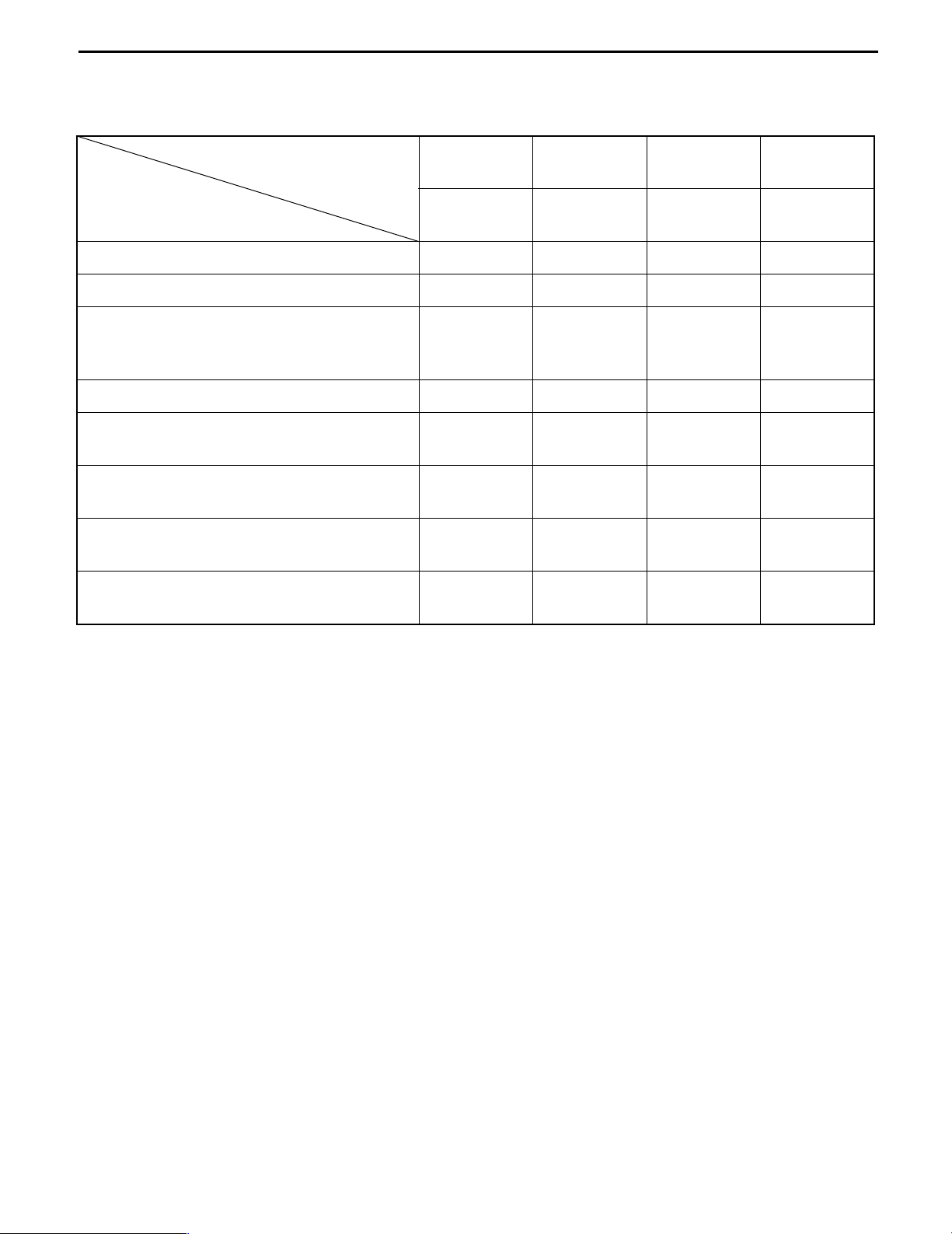
PERIODIC REPLACEMENT OF PARTS AND LUBRICANTS
0-25
●: Replacement
Replacement cycle
Item
Drive unit gear oil ● ←
Hydraulic oil ● ←
Hydraulic oil filter
Rear wheel bearing grease ● ←
Power steering hose
Power steering rubber parts
Hydraulic hose
Lift chain
Every
month
Every
170 hours
● New
vehicle initial
replacement
Every
3 months
Every
500 hours
Every
6 months
Every
1000 hours
● ←
Every
12 months
Every
2000 hours
●Every
2 years
●Every
2 years
●Every
2 years
●Every
3 years

0-26

BATTERY
BATTERY COMPARTMENT AND
REQUIRED WEIGHT
. . . . . . . . . . . . . . . . . . . . . . . . . 1-2
1-1
Page
0
SERVICE STANDARDS. . . . . . . . . . . . . . . . . . . . . . . . 1-3
DISPLAY . . . . . . . . . . . . . . . . . . . . . . . . . . . . . . . . . . . . . 1-3
TROUBLESHOOTING . . . . . . . . . . . . . . . . . . . . . . . . . 1-4
BATTERY ASSY . . . . . . . . . . . . . . . . . . . . . . . . . . . . . . 1-5
REMOVAL · INSTALLATION . . . . . . . . . . . . . . . . . . . . . 1-5
INSPECTION . . . . . . . . . . . . . . . . . . . . . . . . . . . . . . . . . 1-6
REPLACING BATTERY PLUG TERMINAL . . . . . . . . . . 1-9
1
2
3
4
5
6
7
8
9
10
11
12
13
14
15
16
16
18
 Loading...