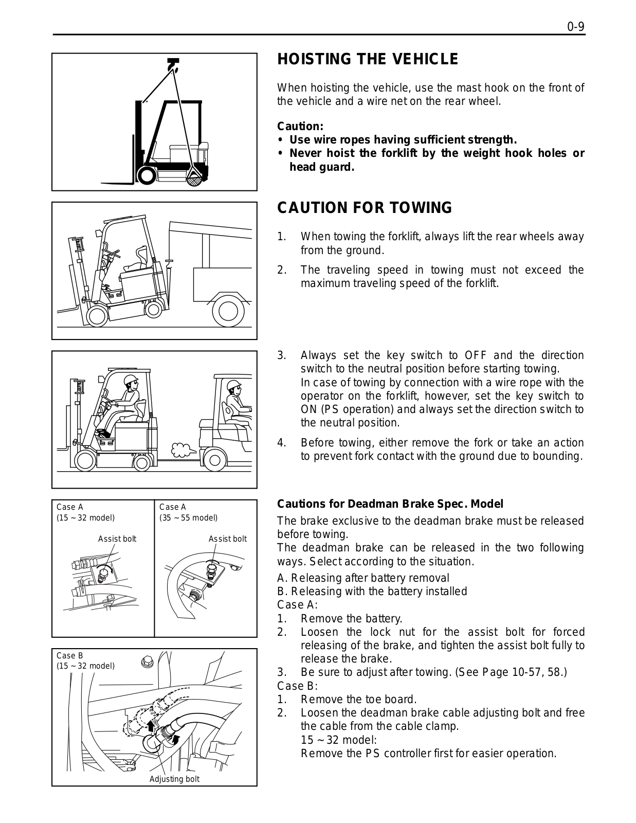
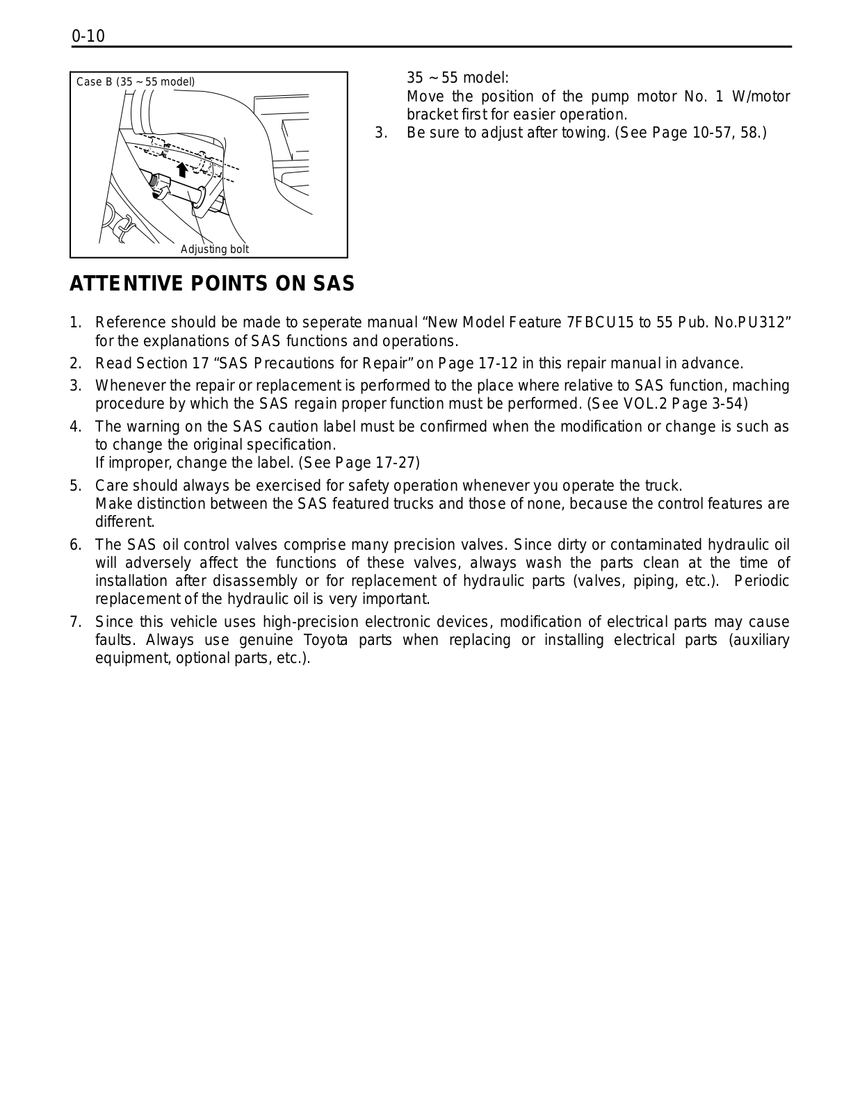
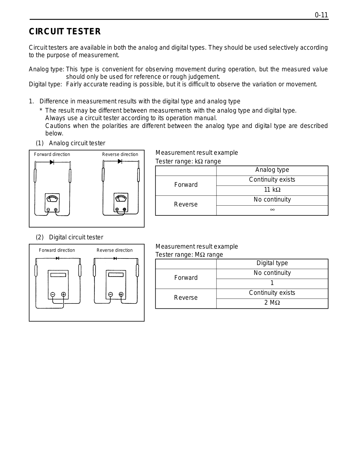
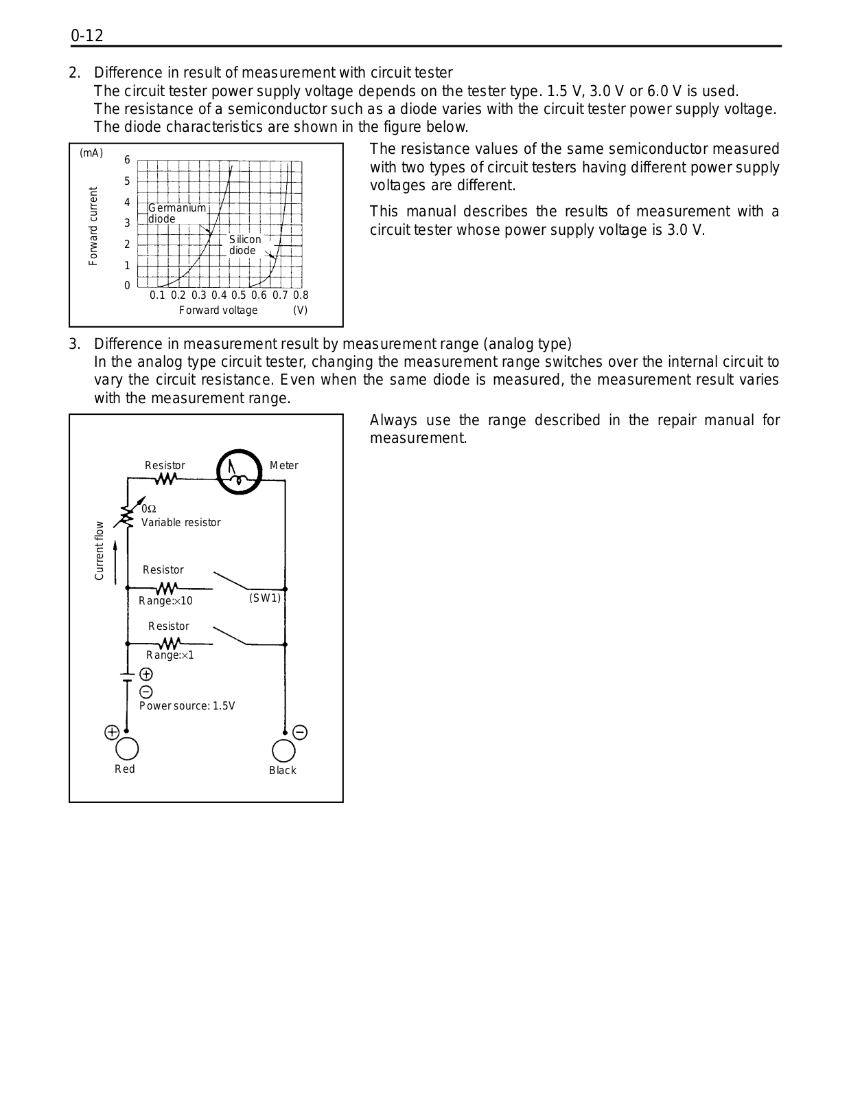
How it Works
Log In / Sign Up
Buy Points
How it Works
FAQ
Contact Us
Questions and Suggestions
Users
Toyota
Loading...
#
4Runner 2012
7
4Runner 2013
6
4Runner 2014
5
4RUNNER 2015
4
4RUNNER 2016
3
4Runner 2017
4
4Runner 2018
3
4Runner 2019
4
4Runner 2020
2
4Runner Navigation
4WD 1995-2005
4Y
50-4FD100
50-4FDK150
5FD33~45
5
2
5FD70-30
5FDC18-30
5FG
5FG10-30
5FGC
5L-E
5S-FE
6HBW30-6TB50
6
2
62-8FDU15
62-8FDU18
62-8FDU20
62-8FDU25
62-8FDU30
6FD10-30
6FG
2
6HBW23
73700-0W150
4
73700-0W160
4
7BPUE15
7BWS10-13
7
7FBCU
7FBE10
7FBE10-20
7FBEF 15
7FBEF 16
7FBEF 18
7FBEF 20
7FBMF 16
2
7FBMF 18
7FBMF 20
7FBMF 25
7FBMF 30
7FBMF 35
7FBMF 40
7FBMF 45
7FBMF 50
7FGCU35
7FGU
7FGU35-80
7HBW23
2
7HBW30-7TB50
7 LPG
7M-GE
7M-GTE
86120-YZA59
8FBCHU25
8FBCU20-32
8FD
2
8FDU18
8FDU20
8FDU25
8FDU30
8FDU32
8FG
2
8FGCU15
8FGCU20
8FGCU20-32
2
8FGCU25
8FGCU30
8FGCU32
8
50
86
2
850
851
860
5603
5613
6600
7103
7104
2
7131
2
8000
75105
712578
86 2017
10
86 2018
2
86 2019
2
86 2020
5157000
6180010
86720-3090
Loading...
Loading...
Nothing found
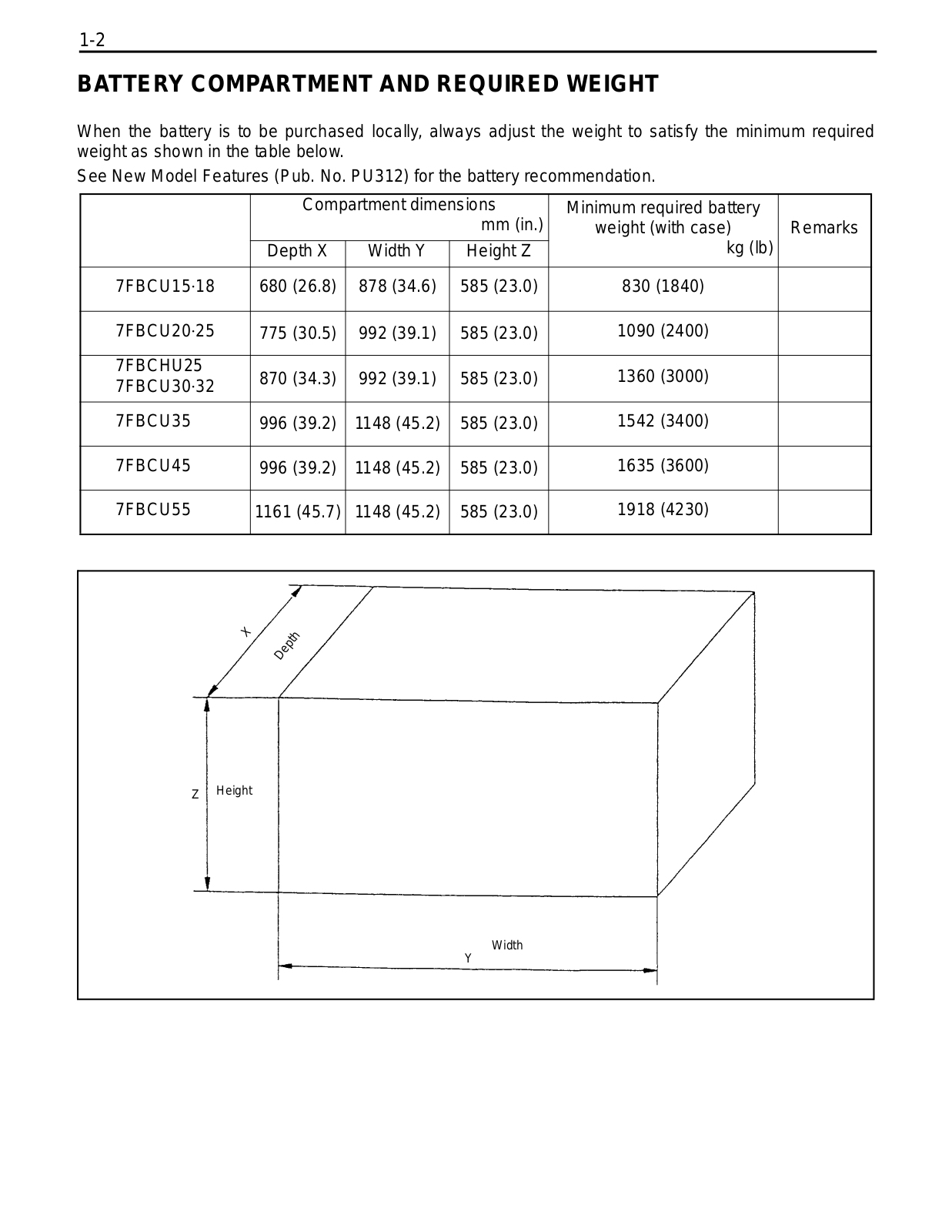
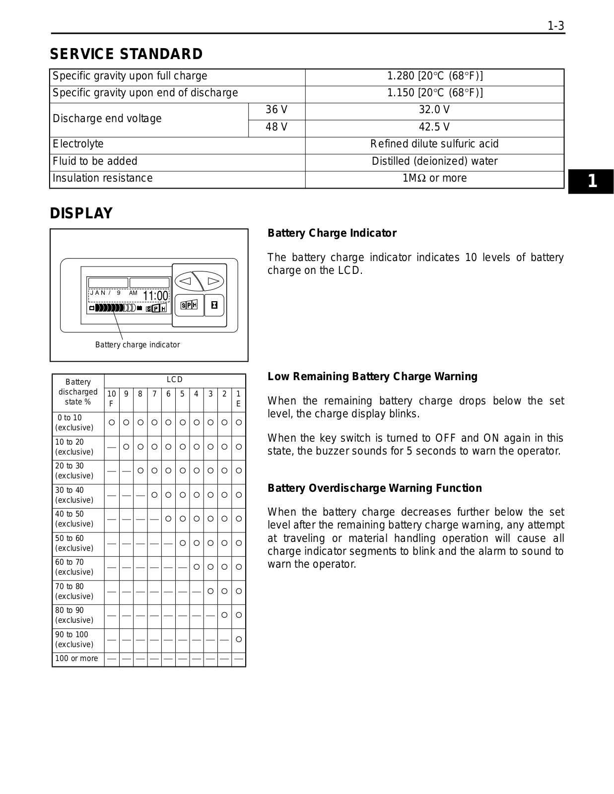
7FBCU
Repair Manual
910 pgs
37.98 Mb
0
Table of contents
Loading...
Toyota 7FBCU Repair Manual
...
Toyota Repair Manual
Download
Specifications and Main Features
Frequently Asked Questions
User Manual
Download
Loading...
+
880
hidden pages
Unhide
You need points to download manuals.
1 point = 1 manual.
You can buy points or you can get point for every manual you upload.
Buy points
Upload your manuals
 Loading...