

Page 1
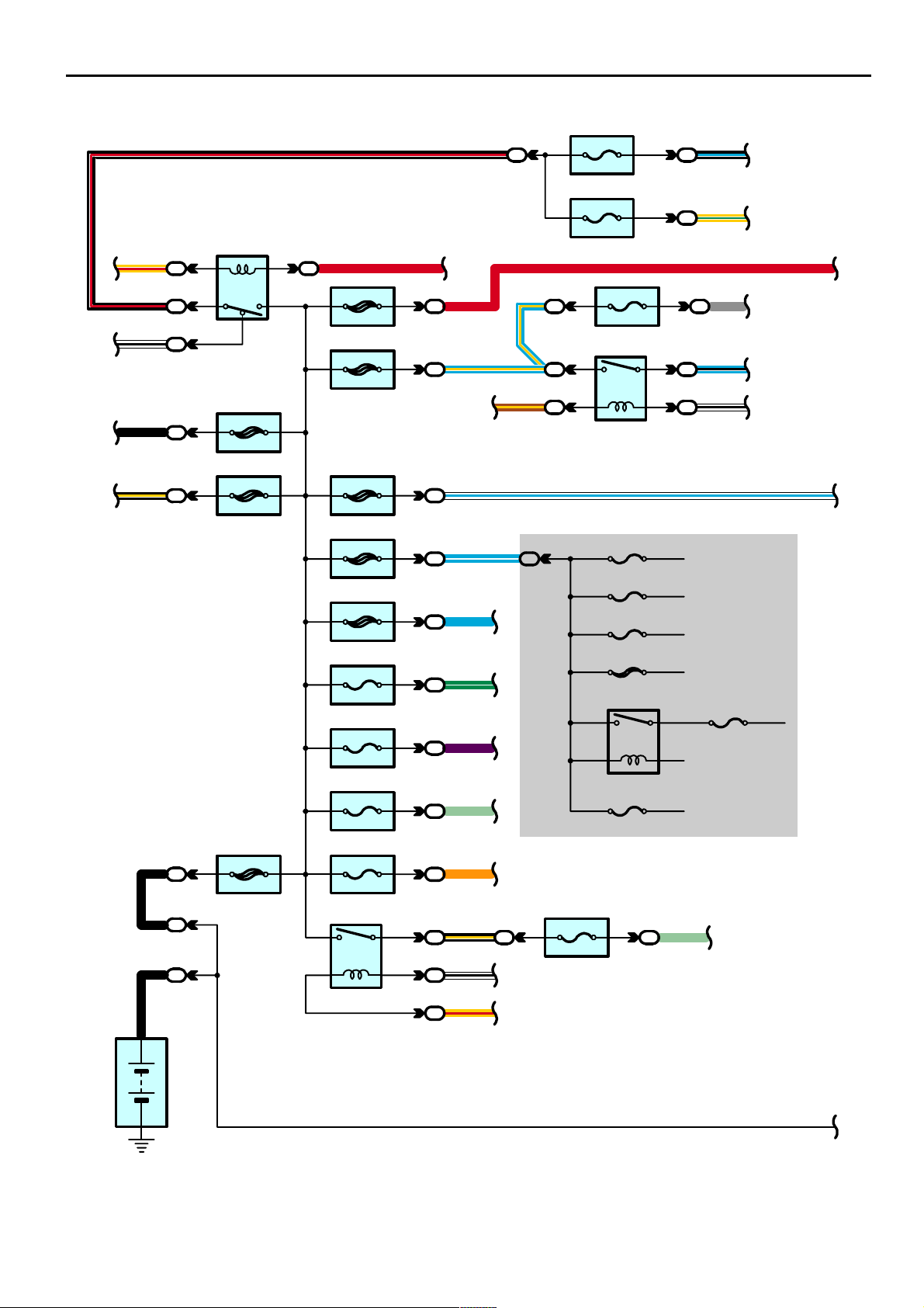
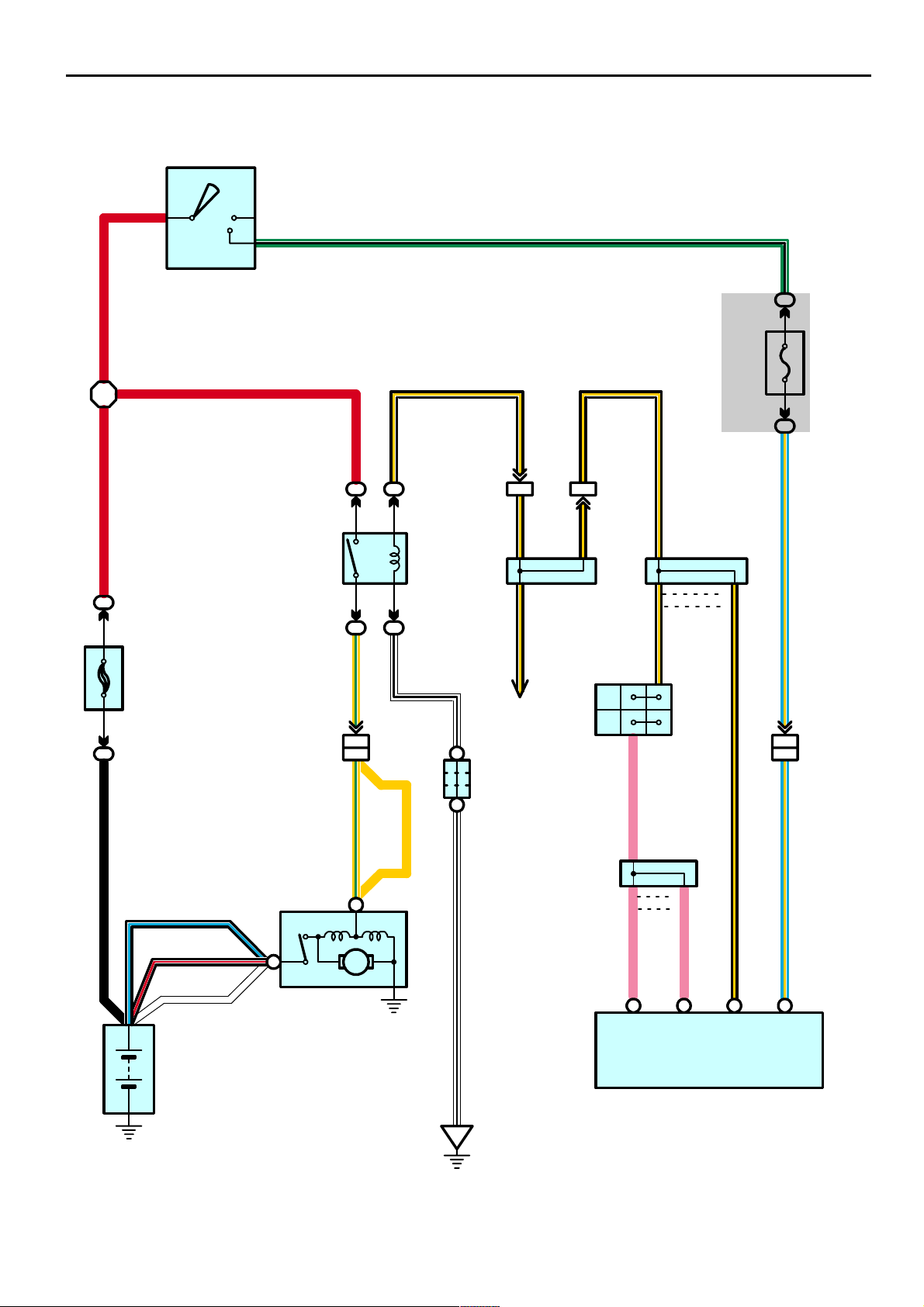
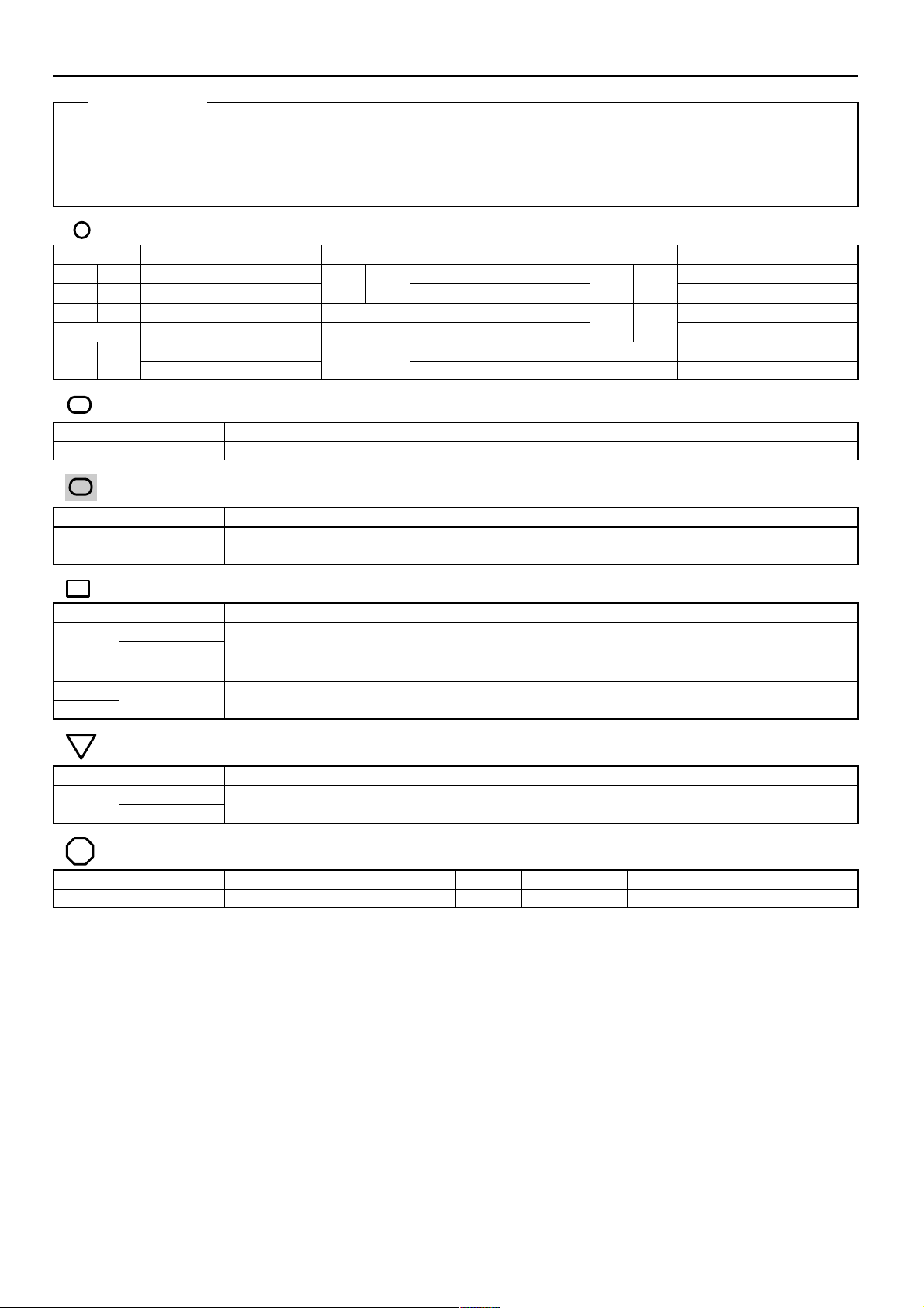
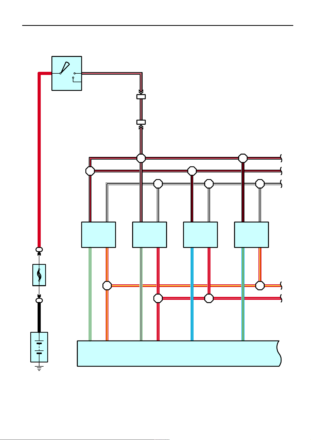
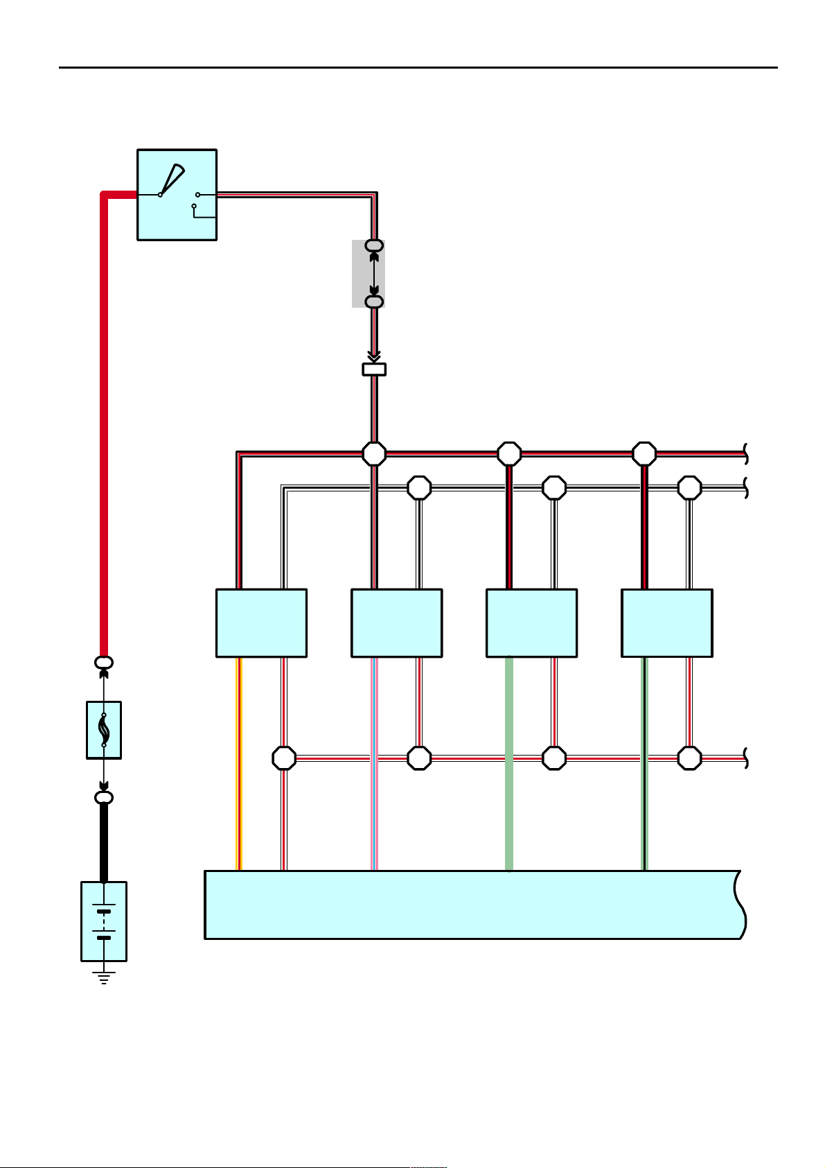
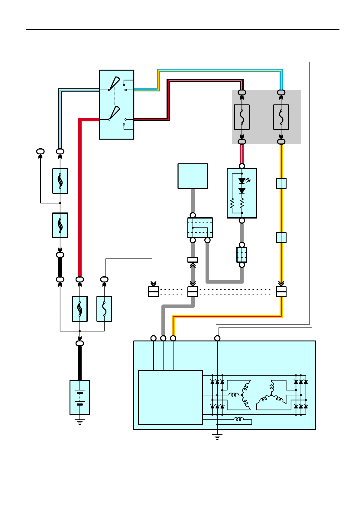
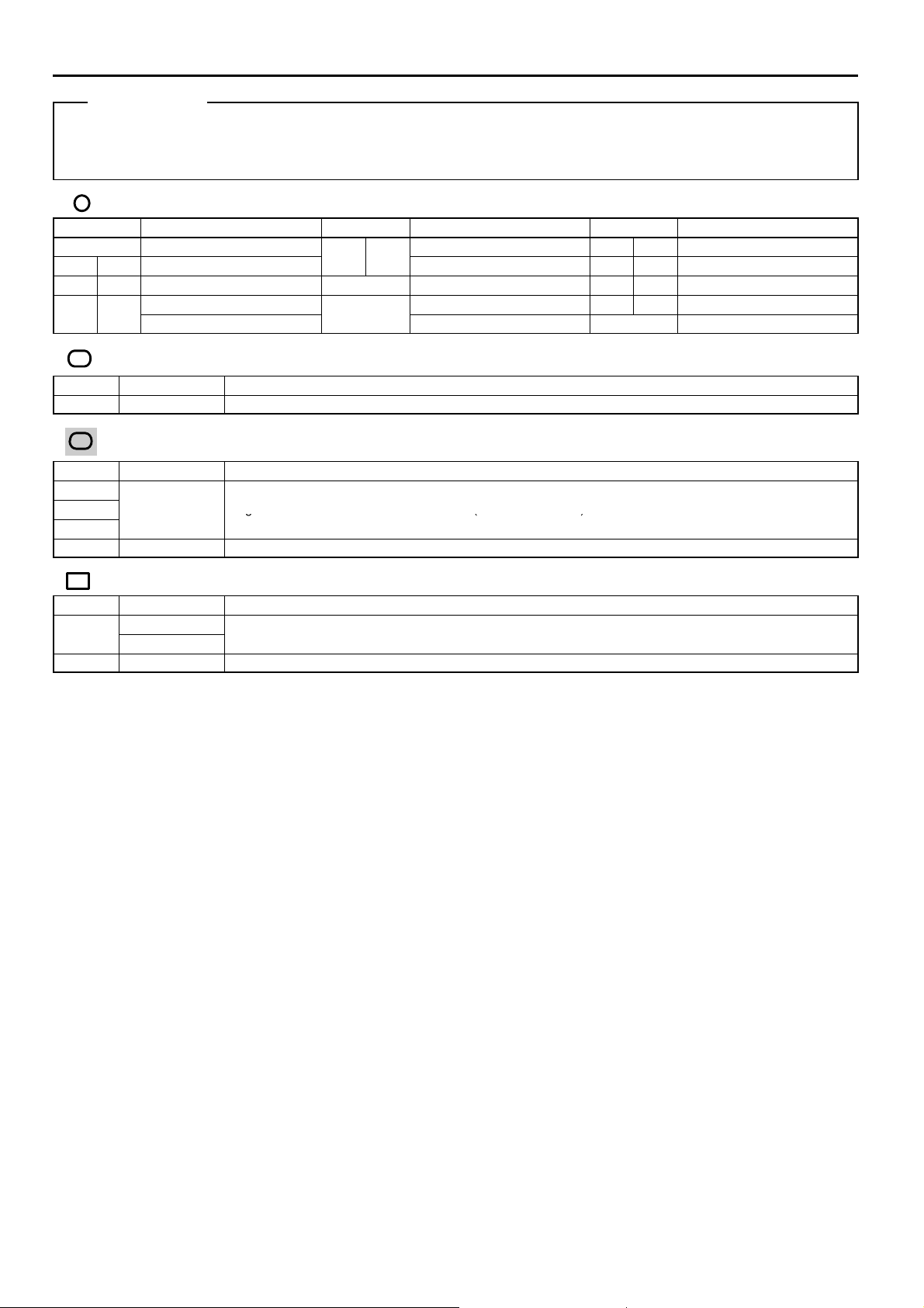
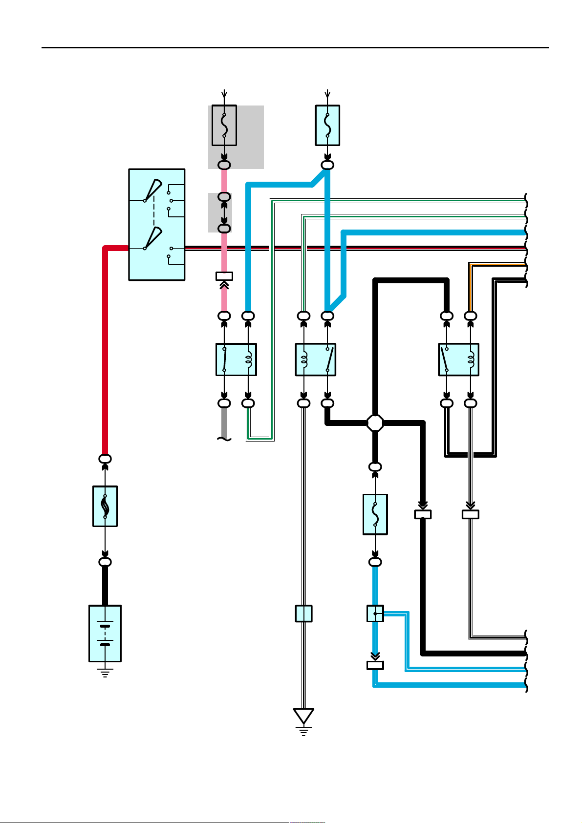
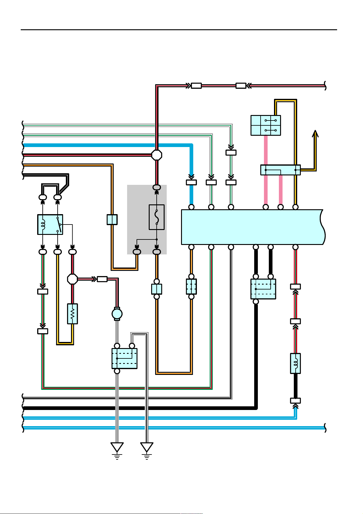
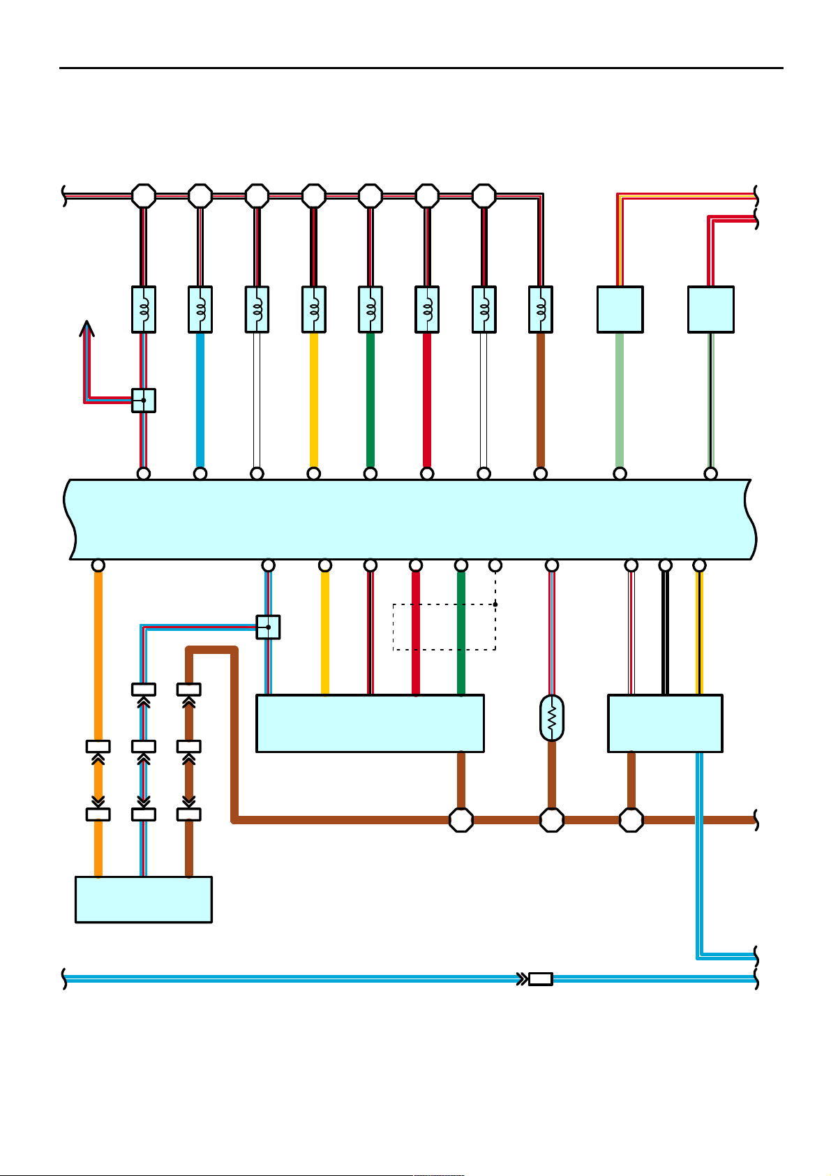
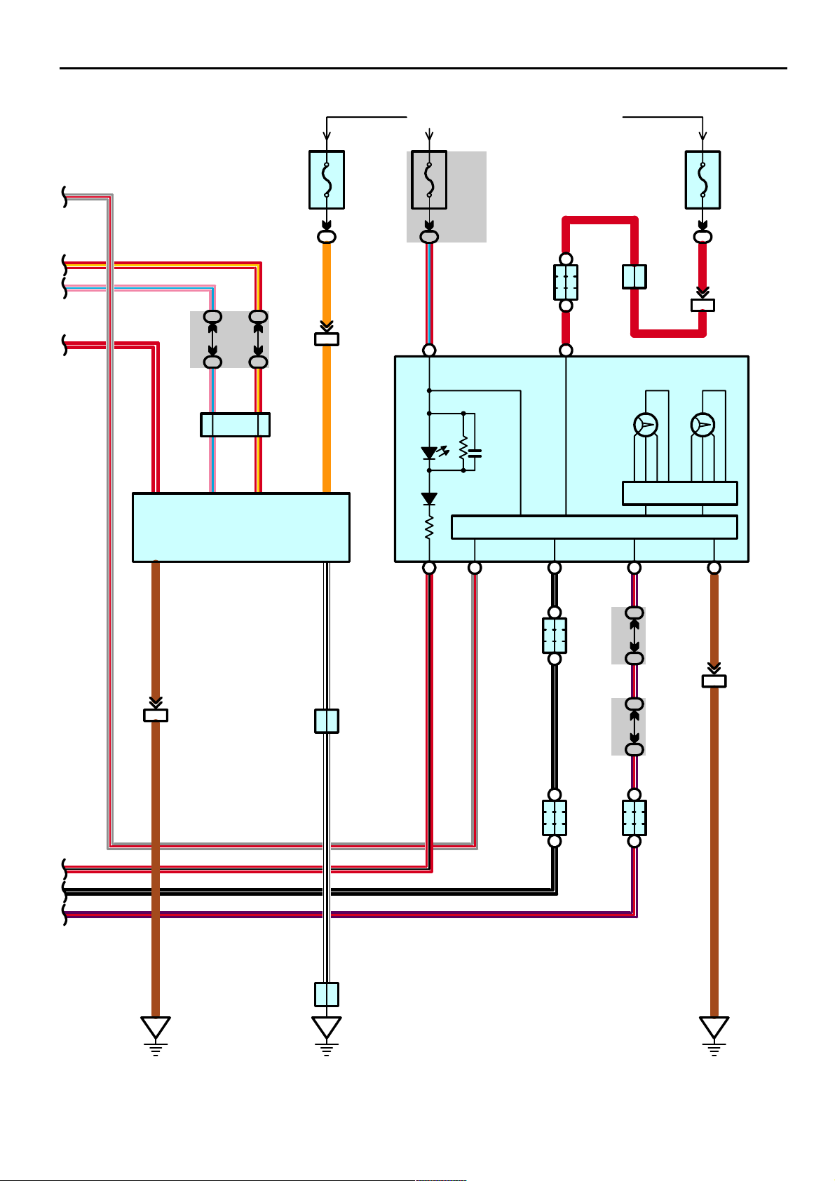
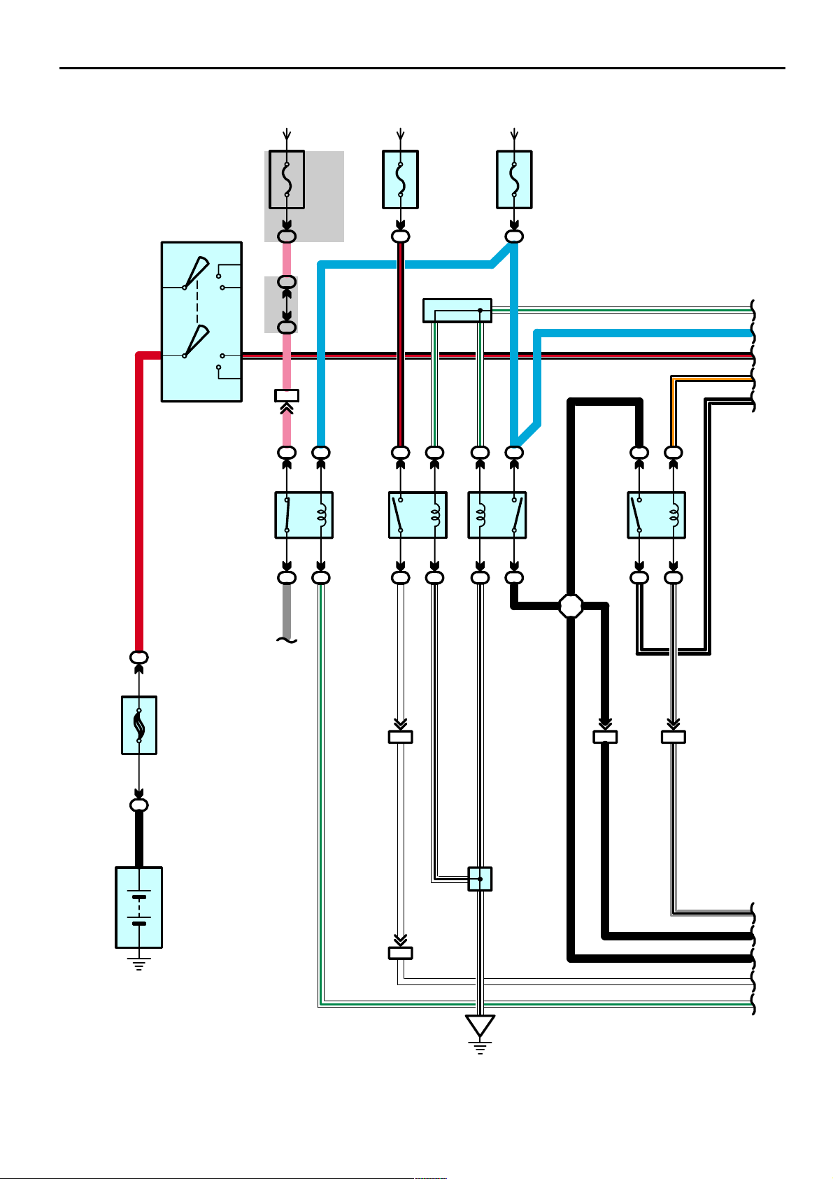
Power Source
B- R
10A MI R HEATER
2
12
30A DEFOG
12
B- L
2
Y- G
2
Y- R
B- R
W- B
B
B- Y
DEFOG Relay
2
2
3
2
2
30A TOWING BRK
2
30A BATT CHG 50A AM1
21 W- L
2
1
2
5
4
12
12
12
12
12
12
12
15A AC1 15V I NV
12
R
50A HEAT ER
50A AI R SUS
50A J/B
40A TOWING
10A STOP
R
2
L- Y
L- W
L
G- W
V
L- Y
BR- Y
1
1C
2
2
2
2
2
2
12
22
10A AIRSUS NO. 2
4
4
5
1
AIR SUS Relay
10A SECU /HORN
30A P P/SEAT
30A D P/SEAT
12
30A POWER
5
1
3
2
3
2
GR
L- B
4
W- B
4
10A TAIL
R
58
140A ALT
1212
2
2
2
BB
Battery
15A FR FOG
12
7. 5A OBD
IG Relay
5
1
3
2
2
2
B- Y
2
W- B
2
Y- R
2
2003 4RUNNER (EWD514U)
TAIL Relay
LG
15A PWR OUTLET
O
25A SEAT HEATER
12
22
LG
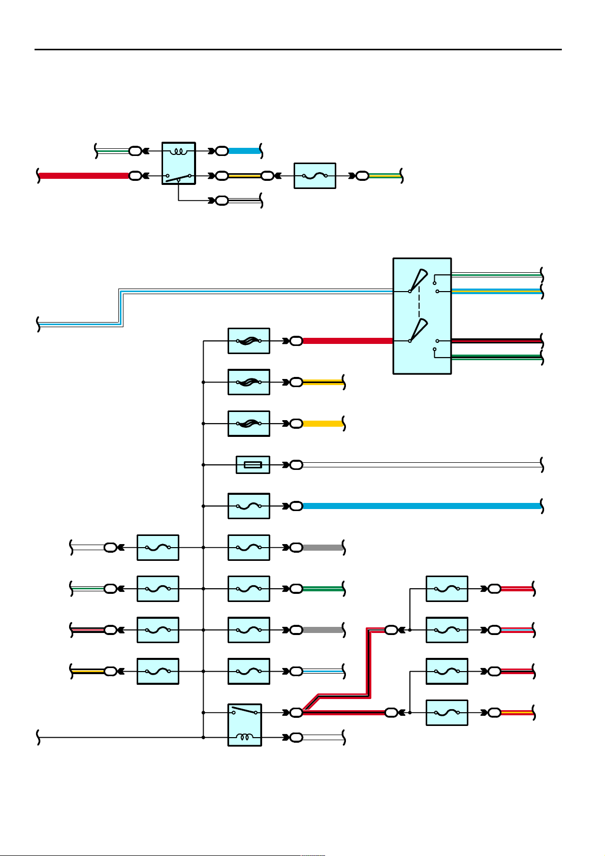
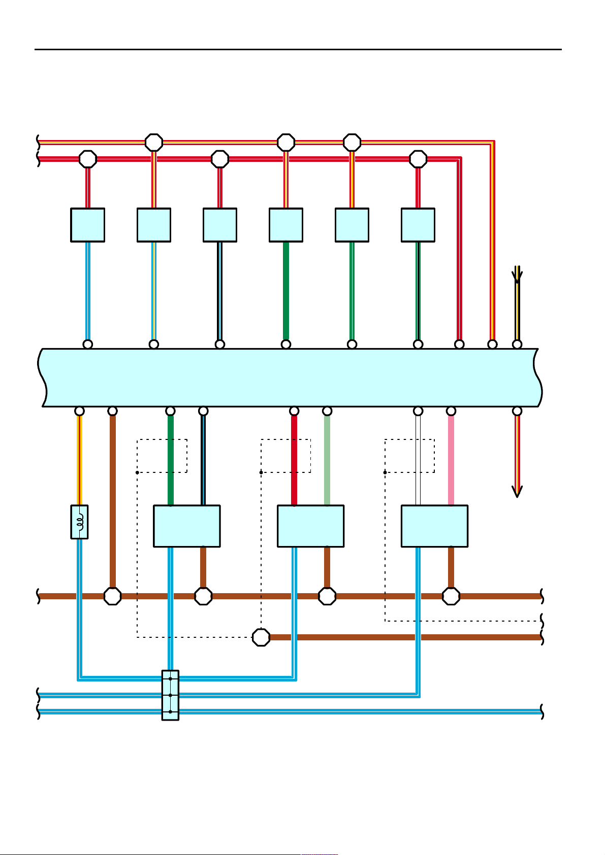
Page 2
2
2
HEATER Relay
1
5
4
2
2
3
2
2
W- G L
B- Y
W- B
7. 5A HEATER NO. 2
12
22
W- L
G- YR
2
AM1
I18
Ignition SW
ACC
IG1
3
4
W- G
L- Y
W- L
W
W- G
B- R
7. 5A ALT- S
21
2
10A HORN
21
2
15A A/F HEATER
21
2
30A AM2
12
40A ABS MTR
1
50A ABS SOL
12
Short Pin
12
20A EFI
12
10A ETCS
12
20A DR/LCK
12
20A TOWING
12
2
2
Y- B
2
2
2
2
2
G- W
2
2
GR
GR
7
R
Y
W
L
AM2
10A HEAD(HI RH
12
10A HEAD(HI LH
2
12
IG2
ST2
6
8
)
)
B- R
G- B
W
L
R- W
2
R- L
2
B- Y
15A TRN- HAZ
21
2
20A RADIO NO. 2
12
HEAD Relay
5
1
3
2
W- L
2
2
2
2003 4RUNNER (EWD514U)
10A HEAD(LO RH
R- B
R- B
W
2
12
10A HEAD(LO LH
12
)
R- B
2
)
R- Y
2
59
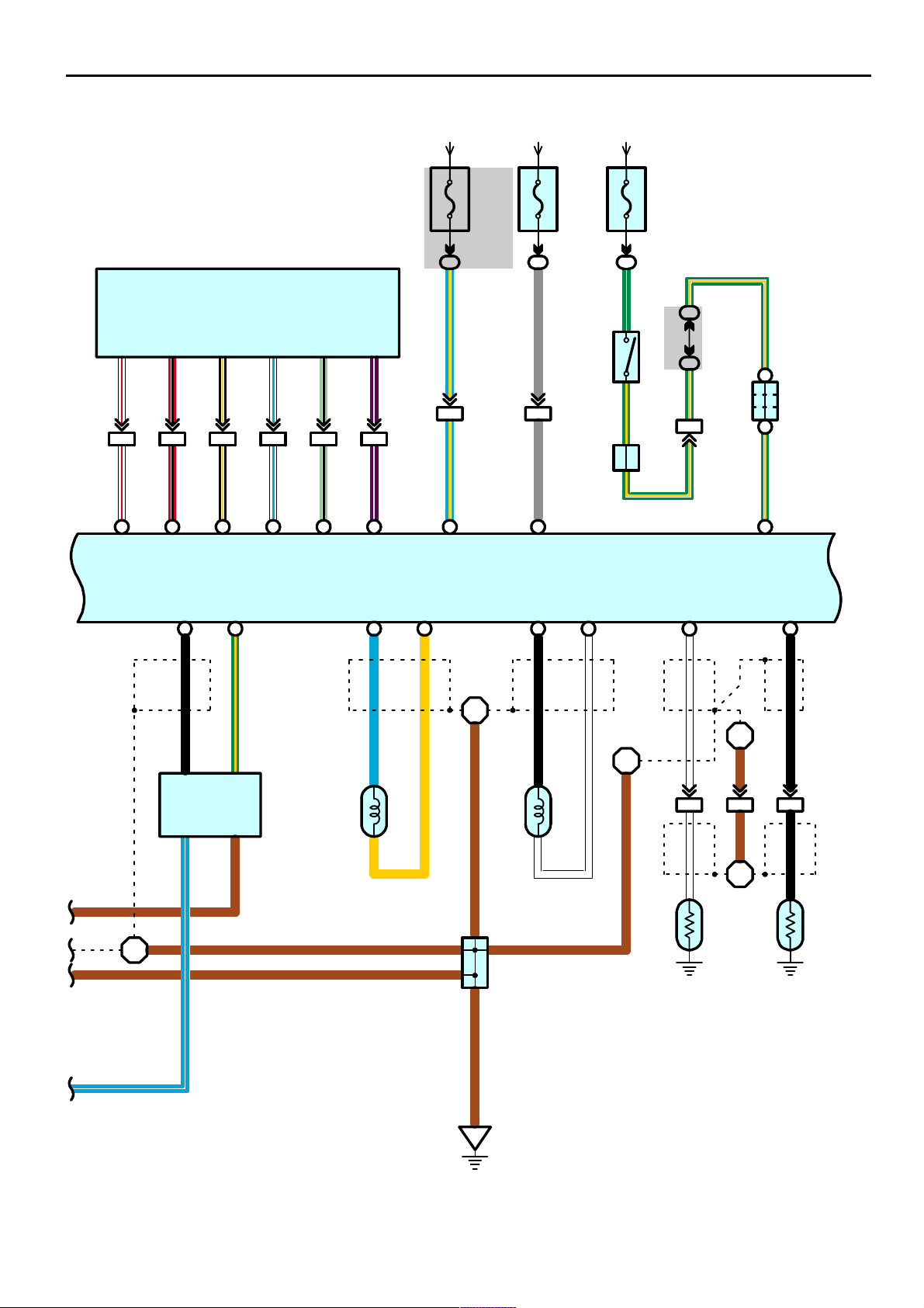
Page 3
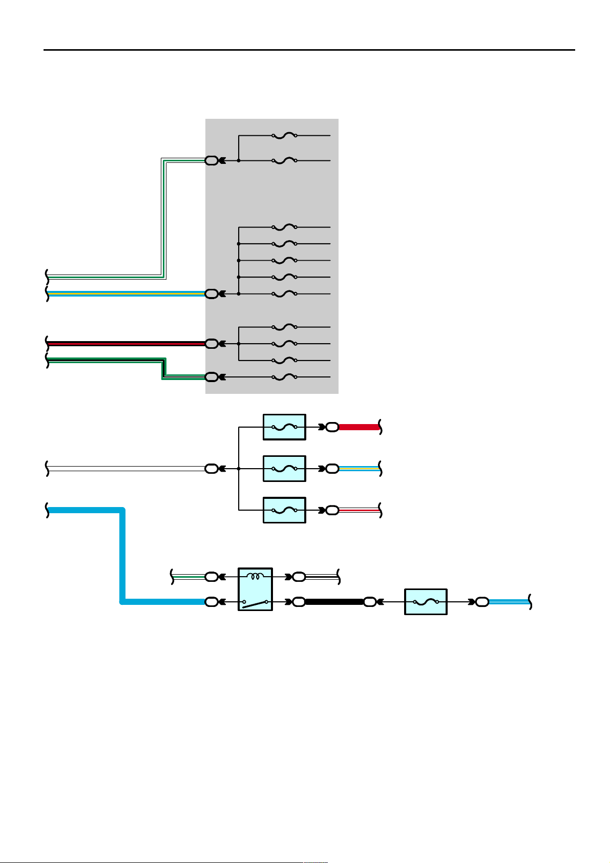
Power Source
7. 5A ACC
W- G
L- Y
B- R
G- B
W- G
5
1D
2
1C
6
1D
3
1D
10A CIG
15A IG1
10A ECU- IG
15A RR WSH
20A 4WD
30A FR WIP- WSH
10A I GN
7. 5A GAUGE
10A SRS
7. 5A STA NO. 2
10A DOME
12
2
R
20A RAD IO NO. 1
W
L
W- G
L
2
2
2
12
10A EC U- B
12
EFI Relay
1
5
2
2
3
22
L- Y
2
W- R
2
W- B
10A EF I NO. 2
BL-W
(
)(
2UZ- FE
12
2
2UZ- FE
)
60
2003 4RUNNER (EWD514U)
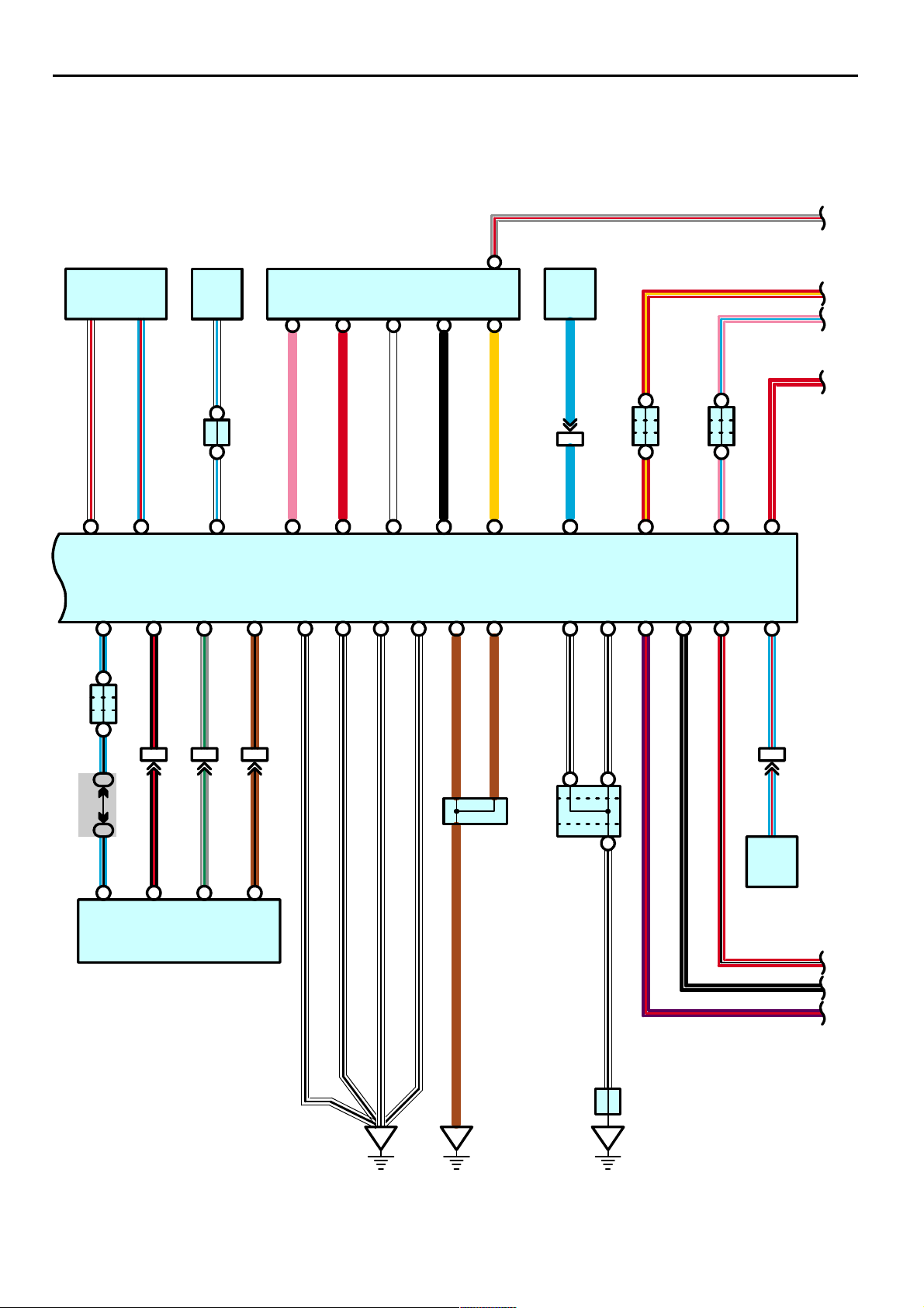
Page 4
Service Hints
HEAD Relay
5-3 : Closed with light control SW at HEAD position or dimmer SW at FLASH position
Closed with engine running and parking brake lever released (w/ daytime running light)
I18 Ignition SW
2-3 : Closed with ignition key at ACC or ON position
2-4 : Closed with ignition key at ON or ST position
7-6 : Closed with ignition key at ON or ST position
7-8 : Closed with ignition key at ST position
TAIL Relay
3-5 : Closed with light control SW at TAIL or HEAD position
: Parts Location
Code See Page Code See Page Code See Page
I18 37
:
Relay Blocks
Code See Page Relay Blocks (Relay Block Location)
2 22 Engine Room R/B (Engine Compartment Left)
4 23 Engine Room R/B No.4 (Engine Compartment Left)
:
Junction Block and Wire Harness Connector
Code See Page Junction Block and Wire Harness (Connector Location)
1C
1D
24 Engine Room Main Wire and Driver Side J/B (Lower Finish Panel)
2003 4RUNNER (EWD514U)
61
Page 5
Starting
78AM2 IG2
ST2
G- B
* 1 : 2UZ- FE
* 2 : 1GR-FE
* 3 : 1GR- FE Cold Area Spec.
* 4 : 1GR- FE Except Cold Area Spec.
7. 5A
STA
NO. 2
(*1)
(*2)
G- BL- Y
1D3
1K2
L- Y
(*1)
IM26
(*2)
IM24
I18
Ignition SW
E 6
RRB
2
2
30A
AM2
1
2
R
R
B- Y
22
51
STA Relay
32
22
Y- G
W- B
(*1)
EA16
(*2)
EA14
)
*1
(
Y- G
B- YB- Y
GG
J35
Junction
Connecto r
G
B- Y
)
B
BB
(
Combination Meter
, J 3
)
A
(
J 2
Junction
Connect or
AB
)
Y
*2
(
B- Y
IM111IC4D2
B- Y
P
N
P 1
Park/Neutral
Position SW
B- Y
(*1)
D
(*2)
A
J28
Junction
Connecto r
D
AA
B- Y
6
9
PP
(*1)
A
(*2)
D
D
62
Battery
B- L
(*3)
B- R
(*1)
W
(*4)
1
S 2(A), S 3(B
Starter
J28
Junction
Connect or
B1
MA
)
W- B
EB
A
A16 B9A17 C12
NSW STAR STA STSW
E 4(A), E 5(B), E 6(C
Engine Control Module
(*1)
A
(*2)
DD
P
B- Y B- Y
)
2003 4RUNNER (EWD514U)
Page 6
Service Hints
I18 Ignition SW
7-8 : Closed with the ignition SW at ST position
S2 (A), S3 (B) Starter
Points closed with the shift lever at P or N position and the ignition SW at ST position
: Parts Location
Code See Page Code See Page Code See Page
E4 A 37
E5 B 37
E6 C 37 J28 38
I18 37 J35 38
J2 A
Code See Page Relay Blocks (Relay Block Location)
2 22 Engine Room R/B (Engine Compartment Left)
Code See Page Junction Block and Wire Harness (Connector Location)
1D 24 Engine Room Main Wire and Driver Side J/B (Lower Finish Panel)
1K 25 Instrument Panel Wire and Driver Side J/B (Lower Finish Panel)
33 (2UZ-FE)
35 (1GR-FE)
:
Relay Blocks
:
Junction Block and Wire Harness Connector
J3 B
P1
33 (2UZ-FE)
35 (1GR-FE)
33 (2UZ-FE)
35 (1GR-FE)
S2 A
S3 B
33 (2UZ-FE)
35 (1GR-FE)
33 (2UZ-FE)
35 (1GR-FE)
:
Connector Joining Wire Harness and Wire Harness
Code See Page Joining Wire Harness and Wire Harness (Connector Location)
EA1
IC4 48 Instrument Panel Wire and Engine Room Main Wire (Left Kick Panel)
IM1
IM2
Code See Page Ground Points Location
EB
Code See Page Wire Harness with Splice Points Code See Page Wire Harness with Splice Points
E6 44 (2UZ-FE) Engine Room Main Wire E6 46 (1GR-FE) Engine Room Main Wire
44 (2UZ-FE)
46 (1GR-FE)
52 Engine Wire and Instrument Panel Wire (Right Side of Blower Unit)
:
Ground Points
44 (2UZ-FE)
46 (1GR-FE)
:
Splice Points
Engine No.2 Wire and Engine Room Main Wire (Under the Engine Room R/B)
Front Left Fender
2003 4RUNNER (EWD514U)
63
Page 7
Ignition (2UZ-FE)
76AM2 IG2
I18
Ignition SW
R RB
B- R
ST2
EA14
B- RB- R
EB16
B- R B- RB- R
E 5
B- R
14 14 14
B- R
W- B
E 2
E 5
W- B
E 3 E 3
B- R
W- B
B- R
E 2
B- RB- R
W- B
B- R
B- R
W- BW- B
E 3
W- B
41
I 1
Ignition Coil and
2
2
30A
AM2
1
2
Battery
Igniter No. 1
32 32 32
LG
LG
924 823 25 11
IGT1
R- Y
E 3
R- Y
I 2
Ignition Coil and
Igniter No. 2
LG- B
LG- B
IGT2
R- W
E 3
R- W
IGF2
E 4
Engine Control Module
R- YR- Y
R- W
I 3
Ignition Coil and
Igniter No. 3
L- W
L- W
IGT3IGF1
R- W
E 3
R- Y
R- W
I 4
Ignition Coil and
Igniter No. 4
IGT4
23
L- Y
L- Y
R- Y
R- Y
E 3
R- W
64
2003 4RUNNER (EWD514U)
Page 8
B- R B- R B- RB- R
E 2
E 2
B- R
R- Y
R- W
E 5
E 3
B- R
I 5
Ignition Coil and
Igniter No. 5
B- L
B- L
W- B
41
23
R- W
E 3
B- R
W- BW- B
R- Y
R- W
E 5
W- B
E 3
B- R
I 6
Ignition Coil and
Igniter No. 6
G
G
W- B
41
23
R- Y
E 3
R- Y
R- W
B- R
I 7
Ignition Coil and
Igniter No. 7
G- W
G- W
E 3
W- B
41
23
R- Y
B- R
W- B
E 3
B- R
I 8
Ignition Coil and
Igniter No. 8
G- B
G- B
W- B
41
23
R- W
W- B
W- B
B- R
)
2
Ignition No. 1
N 1
Noise Filter
(
1
BR
)
2
Ignition No. 2
N 2
Noise Filter
(
1
BR B- R
12 26 13 10
IGT5
IGT6
E 4
Engine Control Module
IGT7
2003 4RUNNER (EWD514U)
IGT8
EE
ED
EC
65
Page 9
Ignition (2UZ-FE)
Service Hints
I18 Ignition SW
7-6 : Closed with the ignition SW at ON or ST position
: Parts Location
Code See Page Code See Page Code See Page
E4 37 I4 33 (2UZ-FE) I8 33 (2UZ-FE)
I1 33 (2UZ-FE) I5 33 (2UZ-FE) I18 37
I2 33 (2UZ-FE) I6 33 (2UZ-FE) N1 33 (2UZ-FE)
I3 33 (2UZ-FE) I7 33 (2UZ-FE) N2 33 (2UZ-FE)
:
Relay Blocks
Code See Page Relay Blocks (Relay Block Location)
2 22 Engine Room R/B (Engine Compartment Left)
:
Connector Joining Wire Harness and Wire Harness
Code See Page Joining Wire Harness and Wire Harness (Connector Location)
EA1 44 (2UZ-FE) Engine No.2 Wire and Engine Room Main Wire (Under the Engine Room R/B)
EB1 44 (2UZ-FE) Engine No.2 Wire and Engine Wire (Near the Starter)
:
Ground Points
Code See Page Ground Points Location
EC 44 (2UZ-FE) Right Bank Cylinder Head
ED 44 (2UZ-FE) Left Bank Cylinder Head
EE 44 (2UZ-FE) Rear Side of Right Bank Cylinder Block
:
Splice Points
Code See Page Wire Harness with Splice Points Code See Page Wire Harness with Splice Points
E2
44 (2UZ-FE) Engine Wire
E3
E5 44 (2UZ-FE) Engine Wire
66
2003 4RUNNER (EWD514U)
Page 10

Memo
2003 4RUNNER (EWD514U)
67
Page 11
Ignition (1GR-FE)
76AM2 IG2
I18
Ignition SW
R RB
B- R
ST2
1D6
1H4
B- RB- R
IM113
E 5 E 5
E12 E12
B- R
14 14 14
W- B
B- R
W- B
W- B
B- R
41
E12
W- B
B- R
W- BW- B
B- RB- R
W- B
E 5
B- R
I 1
Ignition Coil and
2
2
30A
AM2
1
2
Battery
Igniter No. 1
32 32 32
Y- R
Y- R
824 9 10 11
IGT1
W- R
E 9 E 9 E 9
W- R
I 2
Ignition Coil and
Igniter No. 2
P- L
P- L
IGT2
W- R
E 4
Engine Control Module
I 3
Ignition Coil and
Igniter No. 3
LG
LG
IGT3IGF
W- R
I 4
Ignition Coil and
Igniter No. 4
IGT4
23
LG- B
LG- B
W- R
W- RW- RW- RW- R
E 9
68
2003 4RUNNER (EWD514U)
Page 12
B- R
E 5
B- R
E 5
E12
B- R
41
I 5
Ignition Coil and
Igniter No. 5
GR
W- R W- R
GR
12 13
IGT5
23
W- BW- B
W- B
W- R
E 9
E12
B- R
I 6
Ignition Coil and
Igniter No. 6
L
L
IGT6
W- B
41
23
W- R
W- B
W- B
B- R
)
2
Ignition No. 1
N 1
Noise Filter
(
1
W- B
E12
W- B
E 4
Engine Control Module
EF
69
2003 4RUNNER (EWD514U)
Page 13
Ignition (1GR-FE)
Service Hints
I18 Ignition SW
7-6 : Closed with the ignition SW at ON or ST position
: Parts Location
Code See Page Code See Page Code See Page
E4 37 I3 35 (1GR-FE) I6 35 (1GR-FE)
I1 35 (1GR-FE) I4 35 (1GR-FE) I18 37
I2 35 (1GR-FE) I5 35 (1GR-FE) N1 35 (1GR-FE)
:
Relay Blocks
Code See Page Relay Blocks (Relay Block Location)
2 22 Engine Room R/B (Engine Compartment Left)
:
Junction Block and Wire Harness Connector
Code See Page Junction Block and Wire Harness (Connector Location)
1D 24 Engine Room Main Wire and Driver Side J/B (Lower Finish Panel)
1H 25 Instrument Panel Wire and Driver Side J/B (Lower Finish Panel)
:
Connector Joining Wire Harness and Wire Harness
Code See Page Joining Wire Harness and Wire Harness (Connector Location)
IM1 52 Engine Wire and Instrument Panel Wire (Right Side of Blower Unit)
:
Ground Points
Code See Page Ground Points Location
EF 46 (1GR-FE) Rear Side of Left Bank Cylinder Block
:
Splice Points
Code See Page Wire Harness with Splice Points Code See Page Wire Harness with Splice Points
E5
46 (1GR-FE) Engine Wire
E9
E12 46 (1GR-FE) Engine Wire
70
2003 4RUNNER (EWD514U)
Page 14

Memo
2003 4RUNNER (EWD514U)
71
Page 15
Charging
ACC
2
W- L
W
2
W- L
2
2
1
2
140A A LT 50A AM1
1
2
B
22 2
R
R
22
AM1
7
I18
Ignition SW
W
IG1
IG2
ST2
4
L- Y
6AM2
B- R
B 4
Body ECU
)
B
(
, J19
)
A
(
J18
Junction
EA12
EA11
14
Connector
L
BE
AAAA
IC4D6
GR GR GR
EA15
EA13
B- R
L- Y
1D6
7. 5A
GAUGE
1G4
R- L
C15
)
D
(
Charge
, C1 1
)
C
(
C10
Combination Meter
D8
GR
BG
)
B
(
, J 9
)
A
(
AG
J 8
Junction
Connecto r
GR
1C2
15A
IG1
1E20
Y- RY- RY- R
E
Junction
Connecto r
E
D
J 1 J 1
Junction
Connector
D
(
2UZ- FE
(
1GR-FE
)
)
EA13
EA12
72
30A AM2
7. 5A ALT- S
11
2
B
Battery
W
GR
Y- R
B4B2B1A1
LIG B
S
IC Regulator
G 1(A), G 2(B
Gener ator
)
2003 4RUNNER (EWD514U)
Y- R
W
Page 16
g()
Service Hints
G2 (B) Generator
(B) 1-Ground : 13.2-14.0 volts with the engine running at 5000 rpm and 115°C (239°F)
(B) 4-Ground : 0-4 volts with the ignition SW at ON position and the engine not running
: Parts Location
Code See Page Code See Page Code See Page
B4 36
C10 C 37
C11 D 37 I18 37 J18 A 38
G1 A
Code See Page Relay Blocks (Relay Block Location)
2 22 Engine Room R/B (Engine Compartment Left)
Code See Page Junction Block and Wire Harness (Connector Location)
1C
1D
1E
1G 25 Instrument Panel Wire and Driver Side J/B (Lower Finish Panel)
32 (2UZ-FE)
34 (1GR-FE)
:
Relay Blocks
:
Junction Block and Wire Harness Connector
24 Engine Room Main Wire and Driver Side J/B (Lower Finish Panel)
G2 B
J1
32 (2UZ-FE) J8 A 38
34 (1GR-FE) J9 B 38
33 (2UZ-FE) J19 B 38
35 (1GR-FE)
:
Connector Joining Wire Harness and Wire Harness
Code See Page Joining Wire Harness and Wire Harness (Connector Location)
EA1
IC4 48 Instrument Panel Wire and Engine Room Main Wire (Left Kick Panel)
44 (2UZ-FE)
46 (1GR-FE)
Engine No.2 Wire and Engine Room Main Wire (Under the Engine Room R/B)
2003 4RUNNER (EWD514U)
73
Page 17
Engine Control (2UZ-FE)
AM1
76AM2
I18
Ignition SW
ACC
IG1
ST1
IG2
ST2
From Power Source Syste m (See Page 58
7. 5A
ACC
1K8
P
3EF
3EF
B- R
P
IC35
P
2
32
L
2
L
)
1
20A
EFI
2
2
L
L
W- G
22 22
15
L
B
B- O
51
W- G
W- G
L
B- R
B- O
B- W
ACC CUT
Relay
41
2
2
GR
RR
2
2
30A AM2
1
2
B
Battery
W- G
EFI Relay
23
22 22
W- B
B
J 2
Junction
Connect or
B
W- B
B
10A
EFI
NO. 2
B
E 6
B
2
1
2
2
L- W
A
J 4
Junction
Connect or
A
L- W
IC317
C/OPN Relay
32
B
A
L- W
B- W
B
IC4C3 IC4C15
B
GR- B
GR- B
GR- B
GR- B
B
L- W
L- W
74
EB
2003 4RUNNER (EWD514U)
Page 18
EA1
1
B- R B- RB- R
EB1
3
B- R
W- G
W- G
L
B- R
B- O
B- W
B- W
22
23
FUEL PUMP
Relay
15
222
B- Y
G- R
IC4D5
G- R
IM219
G- R
B- R
P 1
Park/Neutral
W- G
B- R
I 2
L
B- R
61D
C
4
B- R
I 1
B- R
2
1
B- R
F 8
J 4
Junction
Connector
C
B- O B- O
B- O
2
IB1
B- R
4
M
F14
Fuel Pump
Resistor
Fuel Pump
5
W- B
BABA
)
B
(
, J41
)
A
(
J40
Junction
Connector
AA
W- B
10A
IGN
)
A
(
1J111E23
BA
J 8
Junction
Connector
BA
B- O B- O
W- B
IC4C4
L
E3E
BATT MREL
IGSW
9E E2
B- O
)
B
(
BB
, J32
)
A
(
J31
Junction
Connector
AB
B- O
W- G
IC4C17
W- G
8
E 4(A), E 5(B), E 6(C), E 7(D), E 8(E
Engine Control Module
FPR FC
G- R
IC316
W- G
IM25
W- G
15 A
ACCR
A33 E10
GR- B
Position SW
J28
B
)
B
(
, J32
)
A
(
J31
Junction
Connector
B
P
N
9
PP
A
Junction
Connector
A
16 A
NSWB9STAR
)
BABA
AC
+B2
B
6
STA Relay
B- Y
D
D
DA
P
B- Y B- Y
A17
STA
CCV+B
27 A1E
R- G
IM217
IE1C3
)
R- G R- GB
1
Canister Closed Valve
(
2
V10
VSV
GR- B
B
L- W
L- W
IB21
L- W
L- W
W- B
W- B
BLBO
75
2003 4RUNNER (EWD514U)
Page 19
Engine Control (2UZ-FE)
B- R B- R B- R B- R B- R B- R B- R
Combinatio n Meter
R- L
PTNK
E21
O
E 3
B- R
1
I 9
Injector No. 1
2
A
A
A
R- L R- L
1A
#1
E 3
B- R
1
I10
Injector No. 2
2
L
J26
Junction
Connector
2#2A3
L- R
BR
E 3
B- R
1
I11
Injector No. 3
I12
2
W
A4
#3
VC
A18
L- RL- R
B
B
B
E 3E 3
B- R
1
Injector No. 4
2
Y
A5
#4
VTA1
A21
Y
J26
Junction
Connector
B- R
1
I13
Injector No. 5
2
G
A
#5
E 4(A), E 5(B), E 6(C), E 7(D), E 8(E
Engine Control Module
VTA2
A31
R- B
E 3
B- R
1
I14
Injector No. 6
2
R
3#6B
M+
C3
)
R
*1
(
E 3
B- R
1
I15
Injector No. 7
2
W
6#7C
)
GE01
M-
C17
C2
G
B- RBR
1
I16
Injector No. 8
2
5#8C
THW
A19
R- L
R- Y
2
I 1
Ignition Coil and
Igniter No. 1
LG
A9
IGT1
VG
W- R
I 2
Ignition Coil and
Igniter No. 2
E2G
A30
A29
B- W
R- Y
R- W
2
33
LG- B
A8
IGT2
THA
A20
Y- B
OO
IE1A10 IE1A16 IE1A17
BC2
10
O
231
PTNK VCC GND
V 8
Vapor Pressur e Sensor
L- R
L- R
BC28BC216
L- R
76
IM222IM27
BR
BR
BR
56421
T 2
Throt tle Con trol Motor
Throt tle Po sition Sensor
313
BR
I 8
2
1
E 2
Engine Coolant
Temp. Se nsor
BR
BRBRBR
I 8
18
IM2
542
M 1
Mass Air Flow
Meter
BR
I 8
THAE2GVGVC VTA1 VTA2 M+ M-
+BE2E2
L- W
BR
L- W
L- WL- W
2003 4RUNNER (EWD514U)
Page 20
* 1 : Shielded
R- Y
R- W R- W R- W R- W
R- W
I 3
Ignition Coil and
Igniter No. 3
333333
L- W
A25
IGT3
PRG
A34
E2
A28
E 3
R- Y
I 4
Ignition Coil and
Igniter No. 4
L- Y
A11
IGT4
OX2A
B22
R- Y R- Y
R- W
222
I 5
Ignition Coil and
Igniter No. 5
B- L
A12
IGT5
E 4(A), E 5(B), E 6(C), E 7(D), E 8(E
Engine Control Module
HT2A
B33
R- Y
R- W
A13
E 3E 3E 3
R- W
2
I 8
Ignition Coil and
Igniter No. 8
MG CLT Relay
R- Y
A2423 A
IGF1
B- Y
D2
ACMG
LCKI
C23
G- B
A10
IGT8
OX2B
B21
R- W
IGF2
HT2B
B25
I 7
HT1A
E 3
R- Y
22
Ignition Coil and
Igniter No. 7
G- W
IGT7
)
B4
E 3
R- Y
I 6
Ignition Coil and
Igniter No. 6
G
A26
IGT6
OX1A
B23
BR
L- W
L- W
V 2
1
)
EVAP
(
VSV
2
)
*1
BR
Y- R
L- W
(
BR
I 8
L- W L- W
G
+B E1 +B E1 +B E1
24 24
L- W
L- W
E
E
E
J28
Junction
Connector
B- L
BR
I 8 I 8 I 8
E
L- W
E
L- WE
E
)
*1
(
)
Bank 2 Sensor 1
H 7
Heated Oxygen Sensor
(
I 9
R
OX HT OX HTHTOX
L- W
BR BR
LG
BR
)
*1
(
)
Bank 1 Sensor 1
H 5
Heated Oxygen Sensor
(
BR BRBR BRBR
W
313131
24
L- W
PBR
R- Y
)
A/C Lock Sensor
Bank 2 Sensor 2
H 8
Heated Oxygen Sensor
(
BR
(*1)
L- W
2003 4RUNNER (EWD514U)
77
Page 21
Engine Control (2UZ-FE)
A24
Accel Position Sensor
VPA1 VPA2 VCP1 VCP2 EP1 EP2
634152
W- R
W- R
VPA
R- B
R- B
23 EE22
VPA2
B- Y
B- Y
E27
VCPA
W- L
W- L
E26
VCP2
LG- B
IC4C11 IC389IC3A8 IC4C13 IC4C16 IC4
LG- B
E28
EPAEEPA2
V- W
V- W
29
E 4(A), E 5(B), E 6(C), E 7(D), E 8(E
Engine Control Module
From Power Source System (See Page 58
11
7. 5A
STA
NO. 2
2
1K2
L- YL- Y
IM26
12 C
STSW
)
2
GRGR
IC4C5
6D
+BM
10A
ETCS
)
10A
STOP
2
2
G- W
2
S12
Stop Light SW
1
G- Y
E
J 4
Junction
Connector
E
G- Y
G- Y
3CB
3CB
G- Y
IC315
AH
)
B
(
, J32
)
A
(
BE
J31
Junction
Connector
G- Y
19 D
STP
BR
(*1)
BR
OX1B
)
*1
(
31
24
I 9
HT1B
B29
B
OX HT
+B E1
L- W
G- Y
BR
B5
)
Bank 1 Sensor 2
H 6
Heated Oxygen Sensor
(
BR
BR
NE+
)
L
*1
(
1
C 4
Crankshaf t
Position Sensor
2
NE-
C25
C24
Y
I 9
BR
C
C
C
C
)
*1
(
C 1
Camshaft
C
J28
Junction
Connector
G2+
B
1
Position Sensor
2
G2-
C27
C32
W
I 9
BR
BR
KNK2
B2
)
W
*1
(
(*1)
EB11EB14
)
W
*1
(
11
K 2
Knock Sensor 2
EB12
E 3
BR
BR
E 4
KNK1
B1
)
B
*1
(
)
B
*1
(
K 1
Knock Sensor 1
78
L- W
BR
EF
2003 4RUNNER (EWD514U)
Page 22
* 1 : Shielded
GR- R
T 8
Transp onder Key
Computer
EFIO
6
W- R
)
B
(
, J32
)
A
(
J31
Junction
Connector
EFII
7
L- R
D27 4 D
26 D
IMO
THWO
ACLD
D14
BH
AE
L- B L- B
3DC
3DC
L- B
D33
B- R
IK14IK12IK13
B- R
F 9
4WD Control
ECU
24
)
B
(
J30
Junction
Connector
THE
D32
GR- G
GR- G
)
4WD
(
A32
Airbag Sensor
Assembly
GSW2
23
L
IL12
L
14 E
F/PS
W- B
)
B
(
, J34
)
A
(
J33
Junction
Connector
BCBC
R- Y
P- L
R- Y
)
B
(
AF
, J36
)
A
(
J35
Junction
Connector
BH
R- Y
E18
SILIMI
SPD TACH
D17
15 E1D
W- B
AB
5E E12
V- R
P- L
)
B
(
AE
, J30
)
A
(
J29
Junction
Connector
BA
P- L
20 E
TC
W
11 E
R- B
B- W
R- W
R- W
19 E
WFSE
ELSEOMHP4WDE1ME01E03E02E01
L- R
II14
L- R
15
ELS1
S 8(B), S 9(C
Skid Control ECU
L4
)
W- L
4WD
(
BH
BH
)
W- L
4WD
(
L4
NEO ENG+ ENG- TRC+ TRC-
C7C14 C22 C24 C16
P
17 E
NEO
A/CS
D31
BR- B
BR- B
)
R
24 E
ENG+
E 4(A), E 5(B), E 6(C), E 7(D), E 8(E
Engine Control Module
W- B
W- B
W
30 E
ENG-
7C6A7A 4C
W- B
B
25 E
TRC+
W- B
B16
SP1
Y
31 E
TRC-
)
8B1C
BR
BR
CC
J26
C
Junction
Connector
A7A18 B7B17
ACLDTWI
A16(A), A17(B
A/C Control Assembly
THE
)
ACS
B 4
Body ECU
BR
W- B
W- B
W- B
W- B
EE
EF
A
W- B
IK
J37
Junction
Connector
R- B
B- W
V- R
79
2003 4RUNNER (EWD514U)
Page 23
Engine Control (2UZ-FE)
GR- R
R- Y
P- L
R- W
2
O
3C A
3CCC
P- L
HG
J18
Junction
Connecto r
HG
R- WBR
15 13 7 16
WFSE TC SIL BATT
SG CG
5
IM29
P- L
D 1
Data Link Connec tor 3
3A
A3A
R- Y R- Y
IC4C14
O
4
W- B
E
E
2
7. 5A
OBD
J22
Junction
Connector
From Power Sourc e Syste m (See Page 5 8
7. 5A
GAUGE
1G4
)
B
R- L
C15 C16
Malfunction
Indicator Lamp
)
C
(
, C10
)
B
(
, C 9
)
A
(
C 8
Combination Meter
A76BB5
4B
R- B
GR- R
(
, J 9
)
A
(
J 8
Junction
)
B
(
, J 9
)
A
(
J 8
Junction
Connector
)
11
10A
DOME
R
AH
Connector
BF
R
B- W
BC
AC
B- W
D
J 7
Junction
Connector
D
R
Speedometer
V- R
1G1
1K11
3DB
3DB
2
2
R
IC4C2
Tachomet er
C13
BR
IM17
80
R- B
B- W
V- R
BR
BR
W- B
W- B
A
J 5
Junction
Connector
IGEF
2003 4RUNNER (EWD514U)
)
B
(
AG
, J32
)
A
(
J31
Junc tion
Connector
BF
B- W
V- R V- R
)
B
(
AB
, J30
)
A
(
J29
Junc tion
Connector
BD
V- R
BR
EF
Page 24

System Outline
The engine control system utilizes a microcomputer and maintains overall control of the engine, transmission etc. An outline
of the engine control is given here.
1. Input Signals
(1) Engine coolant temp. signal circuit
The engine coolant temp. sensor detects the engine coolant temp. and has a built-in thermistor with a resistance which
varies according to the engine coolant temp. The engine coolant temp. is input into TERMINAL THW of the engine
control module as a control signal.
(2) Intake air temp. signal circuit
The intake air temp. sensor is installed in the mass air flow meter and detects the intake air temp., which is input as a
control signal to TERMINAL THA of the engine control module.
(3) Oxygen sensor signal circuit
The oxygen density in the exhaust emission is detected and is input as a control signal from the heated oxygen sensors
to TERMINALS OX1A, OX1B, OX2A and OX2B of the engine control module.
(4) RPM signal circuit
The camshaft position is detected by the camshaft position sensor and is input into TERMINAL G2+ of the engine
control module as a control signal. Also, the engine RPM is detected by the crankshaft position sensor and the signal is
input into TERMINAL NE+ of the engine control module.
(5) Throttle position sensor signal circuit
The throttle position sensor detects the throttle valve opening angle as a control signal, which is input into TERMINALS
VTA1 and VTA2 of the engine control module.
(6) Vehicle speed circuit
The vehicle speed sensor detects the vehicle speed, and the signal is input into TERMINAL SPD of the engine control
module via the combination meter, from TERMINAL SP1 of the skid control ECU.
(7) Battery signal circuit
Voltage is constantly applied to TERMINAL BATT of the engine control module. When the ignition SW is turned on, the
voltage for engine control module start up power supply is applied through the EFI relay, to TERMINALS +B and +B2 of
the engine control module. The current from the IGN fuse flows to TERMINAL IGSW of the engine control module, and
voltage is constantly applied to TERMINAL +BM.
(8) Intake air volume signal circuit
The intake air volume is detected by the mass air flow meter, and is input as a control signal to TERMINAL VG of the
engine control module.
(9) Stop light SW signal circuit
The stop light SW is used to detect whether the vehicle is braking or not, and the signal is input into TERMINAL STP of
the engine control module as a control signal.
(10)Starter signal circuit
To confirm whether the engine is cranking, the voltage applied to the starter motor when the engine is cranking is
detected, and is input into TERMINAL STA of the engine control module as a control signal.
(11) Engine knock signal circuit
Engine knocking is detected by the knock sensors, and is input into TERMINALS KNK1 and KNK2 of the engine control
module as a control signal.
(12)A/C SW signal system
The operating voltage of the A/C magnetic clutch is detected and input in the form of a control signal to TERMINAL A/CS
of the engine control module.
2003 4RUNNER (EWD514U)
81
Page 25

Engine Control (2UZ-FE)
2. Control System
∗ SFI system
The SFI system monitors the engine condition through the signals input from each sensors to the engine control module.
The control signal is sent to the engine control module TERMINALS #1, #2, #3, #4, #5, #6, #7 and #8 to operate the
injector (Fuel injection). The SFI system controls the fuel injection by the engine control module in response to the driving
conditions.
∗ ESA system
The ESA system monitors the engine condition through the signals input from each sensors to the engine control module.
The best ignition timing is decided according to this data and the data memorized in the engine control module. The
control signal is output to TERMINALS IGT1, IGT2, IGT3, IGT4, IGT5, IGT6, IGT7 and IGT8, and these signals control the
igniter to provide the best ignition timing.
∗ Heated oxygen sensor heater control system
The heated oxygen sensor heater control system turns the heater on when the intake air volume is low (Temp. of exhaust
emission is low), and warms up the heated oxygen sensors to improve their detection performance. The engine control
module evaluates the signals from each sensors, and outputs current to TERMINALS HT1A, HT1B, HT2A or HT2B to
control the heater.
∗ Fuel pump control system
The engine control module supplies current to TERMINAL FPR, and controls the operation speed of the fuel pump with
the FUEL PUMP relay.
∗ ACIS
The ACIS includes a valve in the bulkhead separating the surge tank into two parts. This valve is opened and closed in
accordance with the driving conditions to control the intake manifold length in two stages, for increased engine output in all
ranges from low to high speeds.
∗ ETCS-i
The ETCS-i controls the engine output at its optimal level in accordance with the opening of the accelerator pedal, under
all driving conditions.
∗ Engine start control system
The engine control module allows power to be supplied from the TERMINAL STAR to the STA relay via park/neutral
position SW until complete combustion is confirmed by engine RPM after the detection of ignition SW ST signal by the
TERMINAL STSW.
With this arrangement, engine can be started without holding the ignition key in the ST position. At the same time, the
TERMINAL ACCR is controlled so that the engine control module turns off ACC CUT relay, shutting off power to the
accessories.
3. Diagnosis System
When there is a malfunction in the engine control module signal system, the malfunctioning system is recorded in the
memory. The malfunctioning system can be found by reading the code displayed on the malfunction indicator lamp.
4. Fail-Safe System
When a malfunction has occurred in any system, there is a possibility of causing engine trouble due to continued control
based on that system. In that case, the fail-safe system either controls the system using the data (Standard values)
recorded in the engine control module memory, or else stops the engine.
82
2003 4RUNNER (EWD514U)
Page 26
Service Hints
EFI Relay
5-3 : Closed with the ignition SW at ON position
E2 Engine Coolant Temp. Sensor
1-2 : Approx. 15.0 kΩ (-20°C, -4° F)
:Approx. 2.45 kΩ (20°C, 68°F)
:Approx. 0.32 kΩ (80°C, 176°F)
:Approx. 0.14 kΩ (110°C, 230°F)
E4 (A), E5 (B), E6 (C), E7 (D), E8 (E) Engine Control Module
BATT-E1 : Always 9.0-14.0 volts
+BM-E1 : Always 9.0-14.0 volts
IGSW-E1 : 9.0-14.0 volts with the ignition SW at ON position
+B, +B2-E1 : 9.0-14.0 volts with the ignition SW at ON position
VC-E1 : 4.5-5.5 volts with the ignition SW at ON position
VTA2-E1 : 2.0-2.9 volts with the ignition SW on and throttle valve fully closed
: 4.7-5.1 volts with the ignition SW on and throttle valve fully open
VTA1-E1 : 0.4-1.0 volts with the ignition SW on and throttle valve fully closed
: 3.2-4.8 volts with the ignition SW on and throttle valve fully open
VPA-E1 : 0.3-0.9 volts with the ignition SW on and throttle valve fully closed
: 3.2-4.8 volts with the ignition SW on and throttle valve fully open
VPA2-E1 : 1.8-2.7 volts with the ignition SW on and throttle valve fully closed
: 4.7-5.1 volts with the ignition SW on and throttle valve fully open
THA-E1 : 0.5-3.4 volts with the idling, intake air temp. 0°C (32° F) -80°C (176°F)
THW-E1 : 0.2-1.0 volts with the idling, engine coolant temp. 60°C (140°F) -120°C (248°F)
STA-E1 : 6.0 volts or more with the engine cranking
W-E1 : 9.0-14.0 volts with the idling and malfunction indicator lamp off
SPD-E1 : Pulse generation with the vehicle moving
STP-E1 : 7.5-14.0 volts with the brake pedal depressed
: Parts Location
Code See Page Code See Page Code See Page
A16 A 36 I2 33 (2UZ-FE) J28 38
A17 B 36 I3 33 (2UZ-FE) J29 A 38
A24 36 I4 33 (2UZ-FE) J30 B 38
A32 36 I5 33 (2UZ-FE) J31 A 38
B4 36 I6 33 (2UZ-FE) J32 B 38
C1 32 (2UZ-FE) I7 33 (2UZ-FE) J33 A 38
C4 32 (2UZ-FE) I8 33 (2UZ-FE) J34 B 38
C8 A 37 I9 33 (2UZ-FE) J35 A 38
C9 B 37 I10 33 (2UZ-FE) J36 B 38
C10 C 37 I11 33 (2UZ-FE) J37 38
D1 37 I12 33 (2UZ-FE) J40 A 40
E2 32 (2UZ-FE) I13 33 (2UZ-FE) J41 B 40
E4 A 37 I14 33 (2UZ-FE) K1 33 (2UZ-FE)
E5 B 37 I15 33 (2UZ-FE) K2 33 (2UZ-FE)
E6 C 37 I16 33 (2UZ-FE) M1 33 (2UZ-FE)
E7 D 37 I18 37 P1 33 (2UZ-FE)
E8 E 37 J2 33 (2UZ-FE) S8 B 39
F8 32 (2UZ-FE) J4 38 S9 C 39
F9 37 J5 38 S12 39
F14 40 J7 38 T2 33 (2UZ-FE)
H5 32 (2UZ-FE) J8 A 38 T8 39
H6 32 (2UZ-FE) J9 B 38 V2 33 (2UZ-FE)
H7 32 (2UZ-FE) J18 38 V8 41
H8 32 (2UZ-FE) J22 38 V10 41
I1 33 (2UZ-FE) J26 38
2003 4RUNNER (EWD514U)
83
Page 27
Engine Control (2UZ-FE)
()
:
Relay Blocks
Code See Page Relay Blocks (Relay Block Location)
2 22 Engine Room R/B (Engine Compartment Left)
:
Junction Block and Wire Harness Connector
Code See Page Junction Block and Wire Harness (Connector Location)
1D
1G
3C
3D
Code See Page Joining Wire Harness and Wire Harness (Connector Location)
EA1 44 (2UZ-FE) Engine No.2 Wire and Engine Room Main Wire (Under the Engine Room R/B)
EB1 44 (2UZ-FE) Engine No.2 Wire and Engine Wire (Near the Starter)
IB1
IB2
IC3
IC4
IE1 50 Instrument Panel Wire and Floor No.2 Wire (Left Kick Panel)
IK1 50 Instrument Panel Wire and Instrument Panel Wire (Left Upper Side of the Glove Box)
IL1 50 Instrument Panel Wire and Instrument Panel Wire (Right Upper Side of the Glove Box)
IM1
IM2
BC2 54 Frame Wire and Floor No.2 Wire (Under the Rear LH Seat)
24 Engine Room Main Wire and Driver Side J/B (Lower Finish Panel)
1E
1J
25 Instrument Panel Wire and Driver Side J/B (Lower Finish Panel)
1K
3A
28 Instrument Panel Wire and Center J/B (Instrument Panel Brace RH)
3E
:
Connector Joining Wire Harness and Wire Harness
48 Floor No.2 Wire and Engine Room Main Wire (Left Kick Panel)
48 Instrument Panel Wire and Engine Room Main Wire (Left Kick Panel)
II1 50 Instrument Panel Wire and Instrument Panel Wire (Instrument Panel Brace LH)
52 Engine Wire and Instrument Panel Wire (Right Side of Blower Unit)
:
Ground Points
Code See Page Ground Points Location
EB 44 (2UZ-FE) Front Left Fender
EE 44 (2UZ-FE) Rear Side of Right Bank Cylinder Block
EF 44 (2UZ-FE) Rear Side of Left Bank Cylinder Block
IG 48 Left Kick Panel
IK 48 Right Kick Panel
BL 54 Floor Seat Crossmember LH
BO 54 Rear Pillar LH
:
Splice Points
Code See Page Wire Harness with Splice Points Code See Page Wire Harness with Splice Points
E3 44 (2UZ-FE) Engine Wire I2 50 Engine Room Main Wire
E4 44 (2UZ-FE) Engine No.2 Wire I8
E6 44 (2UZ-FE)
I1 50
Engine Room Main Wire
50 Engine Wire
I9
84
2003 4RUNNER (EWD514U)
Page 28

Memo
2003 4RUNNER (EWD514U)
85
Page 29
Engine Control (1GR-FE)
AM1
76AM2
I18
Ignition SW
ACC
IG1
IG2
ST2
7. 5A
ACC
1K8
P
F3E
3EF
P
5IC3
P
22
32
From Power Source Syste m (See Page 58
15A
A/F HEATER
22
2
L
J 4
Junc tion
Connector
B
B- R
L
B- R
W- G
2
2
51
)
11
20A
EFI
2
B
B
L
W- G
22 22
15
L
B
B- O
51
W- G
L
B- R
B- O
B- W
ACC CUT Relay
41
22
GR
RR
2
2
30A AM2
1
2
B
Battery
W- G
A/F HEATER Relay
32
2
W
IC4C1
W
IM14
EFI Relay
23
2
W- B
22 22
B
W- B
B
B
J 2
Junction
B
W- B
Connect or
B
E 6
B
C/OPN Relay
32
B- W
B
IC4C3 IC4C15
B
GR- B
GR- B
GR- B
GR- B
B
B
W
W- G
86
EB
2003 4RUNNER (EWD514U)
Page 30
B- R
W- G
L
B- R
B- O
B- W
B- W
22
23
FUEL PUMP
Relay
15
22 2
Y- B
B- Y
IC4D5
Y- B
IM219
Y- B
B- R
P 1
Park/Neutral
Position SW
IM15
L
B- R
1D61H3
C
4
F 8
Fuel Pump
J 4
Junction
Connector
C
B- O B- O
Connector
IB12
B- R
4
M
5
W- B
BABA
AA
W- B
B- O
F14
Fuel Pump
B- R
B- R
I 1
B- R
2
Resistor
1
)
B
(
, J41
)
A
(
J40
Junction
W- B
10A
IGN
)
A
(
J 8
B- R
IC4C4
L
E3E
BATT MREL
IGSW
1J111E23
AB
Junction
Connector
AB
B- O B- O
9E E2
B- O
BB
)
B
(
, J32
)
A
(
AB
J31
Junction
Connector
B- O
W- G
IC4C17
GR- B
P
B9
STAR
ACCR
A14
W- G
5IM2
W- GW- G
16 IC3
W- G
8
E 4(A), E 5(B), E 6(C), E 7(D), E 8(E
Engine Control Module
FPR FC
A33 E10
Y- B
P
N
D
16 A
9
PP
D
D
NSW
6
STA Relay
B- Y
A
A
STA
)
+B1
B
BABA
)
B
(
, J32
)
A
(
AC
J31
Junction
CA
Connecto r
B
A
J28
Junction
Connector
B- Y B- Y
A17
CCV+B
27 A1E
B
B
R- G
IM217
IE1C3
)
R- G R- GB
1
Canister Closed Valve
(
2
V10
VSV
GR- B
B
B
W
W- G
IB21
B
W
B
BLBO
87
2003 4RUNNER (EWD514U)
Page 31

Engine Control (1GR-FE)
B- R B- R B- R B- R B- R
Combinatio n Meter
R- L
E 8
B- R
2
I 9
Injector No. 1
1
D
D
D
R- L R- L
1A
#10
E 8
B- R
2
I10
Injector No. 2
1
B
J27
Junction
Connector
2
A3
#20
E 8
B- R
2
I11
Injector No. 3
I12
1
R
A4
#30
B- R
2
Injector No. 4
1
G
A5
#40
E 4(A), E 5(B), E 6(C), E 7(D), E 8(E
Engine Control Module
From Power Source System (See Page 58
7. 5A
STA
E 8E 8
B- R
2
I13
Injector No. 5
1
Y
A
#50
B- RL
2
I14
Injector No. 6
1
3
B
#60
)
NO. 2
1K2
L- Y
IM24
L- Y
C12
STSW
)
2
1
C 3
Camshaft Timing Oil
Control Valve RH
G- Y
C16 C14C15 C13
OC1+ O C1- O C2+ OC2-
L- B
2
1
C 2
Camshaft Timing Oil
Control Valve LH
L- W
L- R
PTNK
E21
O
IM222IM27
OO
IE1A10 IE1A16 IE1A17
BC2
10
O
231
PTNK VCC GND
V 8
Vapor Pressur e Sensor
L- R
L- R
BC28BC216
L- R
BR
BR
BR
L- R
BR
VC
A18
L- RL- R
B
B
B
56421
T 2
Throt tle Con trol Motor
Throt tle Po sition Sensor
VTA1
J27
Junction
Connector
VTA2
A21
G- B
A31
G- W
M+
C3
)
P
*1
(
M-
C2
L
351
BR
E 8
GE01
C17
VG
E2G
THW
A19
B- L
2
1
E 2
Engine Coolant
Temp. Se nsor
BR
BRBRBR
E 8
A30
R- Y
324
M 1
Mass Air
Flow Meter
BR
E 8
THA
A29
A20
R- B
R- W
THAE2GVGVC VTA1 VTA2 M+ M-
+BE2E2
B
BR
88
12
IM1
2003 4RUNNER (EWD514U)
WW
B
E13
BB
Page 32

* 1 : Shielded
R- Y
C23
LCKI
A/C Lock Se nsor
ACIS
A15
W- RW- RW- R
E 9
W- R
2
I 1
Ignition Coil and
Igniter No. 1
3
Y- R
A8
IGT1
EVP1
A34
W- R
2
I 2
Ignition Coil and
Igniter No. 2
33333
P- L
A9
IGT2
E2
A28
AFL+
B23
W- R
I 3
Ignition Coil and
Igniter No. 3
LG
A10
IGT3
E 4(A), E 5(B), E 6(C), E 7(D), E 8(E
Engine Control Module
AFL-
B31
W- R
I 4
Ignition Coil and
Igniter No. 4
LG- B
A11
IGT4
)
HAFL HAFR
AFR+
B22
E 9E 9E 9
W- R
222
I 5
Ignition Coil and
Igniter No. 5
GR
IGT5
AFR-
B30
W- R W- R
A12
B5B4
E 9
W- R
2
I 6
Ignition Coil and
Igniter No. 6
MG CLT Relay
L
A13
IGT6
OX2B
B29
W- R
IGF
A24
HT2B
B- Y
D2
ACMG
B33
)
*1
BR
G- Y
2
)
ACIS
(
V 1
VSV
1
BW-L
BR
W
B
E13 E13 E13
2
)
EVAP
(
V 2
VSV
1
B
BB B
(
BR
E 8
Y
+B HT + B HT + B E 1
21 21
W
W
A
AA W
BR
J27
Junction
Connecto r
)
*1
(
B- W
)
Bank 2 Sensor 1
A13
Air Fuel Ratio Sensor
(
I 9
P
AF+ AF- OX HTAF-AF+
W
BR BR
L
R- L
)
Bank 1 Sensor 1
A12
Air Fuel Ratio Sensor
(
)
*1
(
B
313434
24
B
LBR
)
Bank 2 Sensor 2
H 8
Heated Oxygen Sensor
(
BRBR
BR
E 8
(*1)
B
2003 4RUNNER (EWD514U)
89
Page 33

Engine Control (1GR-FE)
A24
Accel Position Sensor
VPA1 VPA2 VCP1 VCP2 EP1 EP2
634152
W- R
W- R
VPA
R- B
R- B
23 EE22
VPA2
B- Y
B- Y
E27
VCPA
W- L
W- L
E26
VCP2
LG- B
IC4C11 IC389IC3A8 IC4C13 IC4C16 IC4
LG- B
E28
EPAEEPA2
V- W
V- W
29
E 4(A), E 5(B), E 6(C), E 7(D), E 8(E
Engine Control Module
A32
Airbag Sensor
Assembly
GSW2
23
L
IL12
L
14 E
F/PS
)
From Power Sourc e Syste m (See Page 5 8
11
2
2
GRGR
IC4C5
6D
+BM
10A
ETCS
S12
J 4
Junction
Stop Light SW
Connector
10A
STOP
2
2
G- W
2
1
G- Y
E
E
G- Y
)
G- Y
3CB
3CB
G- Y
IC315
AH
)
B
(
, J32
)
A
(
BE
J31
Junction
Connector
G- Y
19 D
STP
BR
(*1)
BR
OX1B
)
*1
(
31
42
I 9
B
HT1B
B21
W
OX HT
E1 +B
BR
G
B
BR
BR
B25
H 6
Heated Oxygen Sensor
J28
Junction
Connect or
F
F
F
BR
J27
Junction
Connect or
E1
C1
)
Bank 1 Sensor 2
(
BR BR
CC
VV1+
C27
)
R
*1
(
1
V 4
VVT Sensor
RH
2
G
BRC
NE-
W
)
W
*1
(
2
1
C 4
Cranks haft
Position Sensor
NE+
C24
I 9
C25
BR
BR
EE
)
*1
(
I 9
2
V 3
VVT Sensor LH
1
B
I 9
BR
VV2+
C26
(*1)
L
Y
I 9
BR
90
2003 4RUNNER (EWD514U)
Page 34

From Power Source Syste m (See Page 5 8
)
* 1 : Shielded
10A
TAIL
B
B
1L5
G
G
3DD
3DD
J16
Junction
Connector
G
ADAI
BIBD
G
E13 E12
ELS2 ELS
Y- G
30A
DEFOG
D
Y- G
J31(A), J32(B
Junction
Connect or
1
2
2
Y- GY- G
IC4C10
D
)
E 4(A), E 5(B), E 6(C), E 7(D), E 8(E
Engine Control Module
J22
Junction
Connect or
F 9(A), F10(B
4WD Control ECU
)
B
(
J30
Junction
Connector
4D
)
L4
W- L
BH
J28
BH
)
W- L
4WD
(
L4
Junction
ADD
E
Connector
E
8B
4WD
)
GR
GR
A11
ADD Actuator
ADD
3
24 E
ENG+
)
R
W
30 E
ENG-
B16
SP1
B
25 E
TRC+
S 8(B), S 9(C
GRGR
B18A24
EC16
E
)
4WD
(
Skid Control ECU
NEO ENG+ ENG- TRC+ TRC-
C7C14 C22 C24 C16
P
17 E
NEO
GR- R
Y
31 E
TRC-
)
*1
(
(*1)
)
*1
(
EKN2
B20
RR
KNK2
B2
G
E10
ED14ED16
G
22
ED11
E11
K 2
Knock Sensor
2
BR
BR
K 1
)
*1
(
)
*1
(
Knock Sensor
KNK1
B1
B
ED12ED15
B
1
11
EKNK
B28
W
W
)
B
(
, J32
)
A
(
J31
Junction
THWO
Connector
ACLD
D14
BH
AE
L- B L- B
3DC
3DC
L- B
A7A18 B7B17
A16(A), A17(B
A/C Control Assembly
D33
B- R
IK14IK12IK13
B- R
ACLDTWI
)
THE
GR- G
GR- G
THE
A/CS
D32
D31
BR- B
BR- B
ACS
7C6A7A 4C
W- B
W- B
W- B
W- B
W- B
W- B
W- B
W- B
E05E04ME01E0 3E02E01
6B7B
W- B
W- B
W- B
W- B
2003 4RUNNER (EWD514U)
EF
EE
91
Page 35

Engine Control (1GR-FE)
GR- R
T 8
Trans ponder Key
Computer
EFIO
6
W- R
D27
IMI
EFII
7
R- Y
AF
)
B
L- R
26 D
IMO
E 4(A), E 5(B), E 6(C), E 7(D), E 8(E
Engine Control Module
(
, J36
)
A
(
BH
J35
Junction
Connector
R- Y
E18
SIL
From Po wer Source Syste m (See Page 58
1
7. 5A
OBD
2
2
R- Y
P- L
3C A
P- L
AE
)
B
(
, J30
)
A
(
BA
J29
Junction
Connector
P- L
20 E
TC
)
R- W
19 E
WFSE
R- W
3CCC
P- L
J18
Junction
Connector
HG
R- WBR
15 13 7 16
WFSE TC SIL BATT
P- L
3A
A3A
GH
R- Y R- Y
O
IC4C14
O
)
SPD TACH
Connector
W- B
BCBC
EOMHP
15 E1D
W- B
AB
W- B
A
V- R
J37
Junction
Connector
5E
PSW
C10
G- W
1
P 2
Power Steering
Oil Press ure S W
)
B
(
, J34
)
A
(
J33
Junction
W
11 ED17
R- B
B- W
SG CG
D 1
5
Data Link
Connect or 3
IM29
BR
BR
E
E
A
4
W- B
W- B
W- B
J22
Junction
Connector
J 5
Junction
Connector
TAC
9
B- W
B- W
GR- R
R- B
B- W
V- R
92
IK
IGEF
2003 4RUNNER (EWD514U)
Page 36

From Power Source System (See Page 58
)
1
7. 5A
GAUGE
R
1G4
AH
R- L
C15 C16
Malfunction
Indicator Lamp
)
C
(
, C10
)
B
(
, C 9
)
A
(
C 8
Combination Meter
A76BB5
4B
)
B
(
J 7
, J 9
)
A
(
BF
J 8
Junction
Connector
R
Junction
10A
DOME
2
2
D
Connector
D
R
Speedometer
R
IC4C2
Tachomet er
C13
B- W
GR- R
R- B
B- W
V- R
R- B
GR- R
B- W
BC
)
B
(
, J 9
)
A
(
J 8
Junction
AC
AC
B- W
B- W
AG
)
B
(
, J32
)
A
(
BF
J31
Junction
B- W
V- R
1G1
1K11
Connector
3DB
3DB
V- R V- R
AB
)
B
(
, J30
)
A
(
BD
Connector
J29
Junction
V- R
BR
IM17
Connector
BR
2003 4RUNNER (EWD514U)
EF
93
Page 37

Engine Control (1GR-FE)
()
: Parts Location
Code See Page Code See Page Code See Page
A11 34 (1GR-FE) I1 35 (1GR-FE) J31 A 38
A12 34 (1GR-FE) I2 35 (1GR-FE) J32 B 38
A13 34 (1GR-FE) I3 35 (1GR-FE) J33 A 38
A16 A 36 I4 35 (1GR-FE) J34 B 38
A17 B 36 I5 35 (1GR-FE) J35 A 38
A24 36 I6 35 (1GR-FE) J36 B 38
A32 36 I9 35 (1GR-FE) J37 38
C2 34 (1GR-FE) I10 35 (1GR-FE) J40 A 40
C3 34 (1GR-FE) I11 35 (1GR-FE) J41 B 40
C4 34 (1GR-FE) I12 35 (1GR-FE) K1 35 (1GR-FE)
C8 A 37 I13 35 (1GR-FE) K2 35 (1GR-FE)
C9 B 37 I14 35 (1GR-FE) M1 35 (1GR-FE)
C10 C 37 I18 37 P1 35 (1GR-FE)
D1 37 J2 35 (1GR-FE) P2 35 (1GR-FE)
E2 34 (1GR-FE) J4 38 S8 B 39
E4 A 37 J5 38 S9 C 39
E5 B 37 J7 38 S12 39
E6 C 37 J8 A 38 T2 35 (1GR-FE)
E7 D 37 J9 B 38 T8 39
E8 E 37 J16 38 V1 35 (1GR-FE)
F8 34 (1GR-FE) J18 38 V2 35 (1GR-FE)
F9 A 37 J22 38 V3 35 (1GR-FE)
F10 B 37 J27 38 V4 35 (1GR-FE)
F14 40 J28 38 V8 41
H6 34 (1GR-FE) J29 A 38 V10 41
H8 34 (1GR-FE) J30 B 38
:
Relay Blocks
Code See Page Relay Blocks (Relay Block Location)
2 22 Engine Room R/B (Engine Compartment Left)
:
Junction Block and Wire Harness Connector
Code See Page Junction Block and Wire Harness (Connector Location)
1D
1G
1H
3C
3D
24 Engine Room Main Wire and Driver Side J/B (Lower Finish Panel)
1E
1J
25 Instrument Panel Wire and Driver Side J/B (Lower Finish Panel)
1K
1L
3A
28 Instrument Panel Wire and Center J/B (Instrument Panel Brace RH)
3E
94
2003 4RUNNER (EWD514U)
Page 38

:
()
g
Connector Joining Wire Harness and Wire Harness
Code See Page Joining Wire Harness and Wire Harness (Connector Location)
EC1 46 (1GR-FE) Engine Wire and Differential Wire (Near the Front Differential)
ED1 46 (1GR-FE) Engine Wire and Sensor Wire (Rear Side of Right Bank Cylinder Block)
IB1
IB2
IC3
IC4
IE1 50 Instrument Panel Wire and Floor No.2 Wire (Left Kick Panel)
IK1 50 Instrument Panel Wire and Instrument Panel Wire (Left Upper Side of the Glove Box)
IL1 50 Instrument Panel Wire and Instrument Panel Wire (Right Upper Side of the Glove Box)
IM1
IM2
BC2 54 Frame Wire and Floor No.2 Wire (Under the Rear LH Seat)
Code See Page Ground Points Location
EB 46 (1GR-FE) Front Left Fender
EE 46 (1GR-FE) Rear Side of Right Bank Cylinder Block
EF 46 (1GR-FE) Rear Side of Left Bank Cylinder Block
BL 54 Floor Seat Crossmember LH
BO 54 Rear Pillar LH
48 Floor No.2 Wire and Engine Room Main Wire (Left Kick Panel)
48 Instrument Panel Wire and Engine Room Main Wire (Left Kick Panel)
52 Engine Wire and Instrument Panel Wire (Right Side of Blower Unit)
:
Ground Points
IG 48 Left Kick Panel
IK 48 Right Kick Panel
:
Splice Points
Code See Page Wire Harness with Splice Points Code See Page Wire Harness with Splice Points
E6 46 (1GR-FE) Engine Room Main Wire E11 46 (1GR-FE) Sensor Wire
E8 E13 46 (1GR-FE) Engine Wire
E9
E10
46 (1GR-FE) Engine Wire
I1 50 Engine Room Main Wire
I9 50 Engine Wire
95
2003 4RUNNER (EWD514U)
Page 39

Engine Immobiliser System
1
2
1B4
1L4
3EB
3EB
W- R W- R W- R
GND
)
G
G
SIL
7
F
F
R- Y
R- Y
3AA
3AA
R- Y R- Y
D 1
Data Link
Connect or 3
J18
Junction
Connector
J35
Junction
Connector
10A
ECU- B
2
IND
3
From Power Source Syste m (See Page 58
10A
IGN
1J11
B- OB- OB- O
B
J 8
Junction
Connector
B
B
J31
Junction
Connector
B
21 9
EFIO
6
EFII
7
14
I17
Trans ponder Key Ampli fier
P- G
GR- B
KSW
10
GNDTXCTCODEVC5
7541
L
LG- R
1312118
AGNDTXCTCODEVC5D+BIG
CTY
4
T 8
Transponder Key
Computer
W- R
27 2 6
IMI
E 7
Engine Control
Module
L- R
IMO
W- B
B
J33
Junction
Connector
B
W- B
A
A
J37
Junction
Connector
IK
V- W
5
LP
GND
7
W- B
3FB
3FB3FB
W- B
Security
Indicator
Light
A
W- B
II
J24
Junction
Connect or
G- Y
AB
BC
G- Y
2
1
W- BW- B
BA
BA
A
IG
)
B
(
, J15
)
A
(
J14
Junction
Connect or
K 3
Unlock
Warning SW
)
B
(
J15
Junc tion
Connector
J 5
Junction
Connecto r
R- B
F
J18D 3
Junction
Connector
F
R- B
1
D12
Door Courtesy S W
Front LH
96
2003 4RUNNER (EWD514U)
Page 40

()
Service Hints
T8 Transponder Key Computer
1-Ground : Always approx. 12 volts
14-Ground : Always continuity
2-Ground : Approx. 12 volts with ignition SW at ON position
: Parts Location
Code See Page Code See Page Code See Page
D1 37 J8 38 J33 38
D3 37 J14 A 38 J35 38
D12 40 J15 B 38 J37 38
E7 37 J18 38 K3 39
I17 37 J24 38 T8 39
J5 38 J31 38
:
Relay Blocks
Code See Page Relay Blocks (Relay Block Location)
2 22 Engine Room R/B (Engine Compartment Left)
:
Junction Block and Wire Harness Connector
Code See Page Junction Block and Wire Harness (Connector Location)
1B 24 Engine Room Main Wire and Driver Side J/B (Lower Finish Panel)
1J
25 Instrument Panel Wire and Driver Side J/B (Lower Finish Panel)
1L
3A
3E
3F
28 Instrument Panel Wire and Center J/B (Instrument Panel Brace RH)
:
Ground Points
Code See Page Ground Points Location
IG 48 Left Kick Panel
II 48 Instrument Panel Brace RH
IK 48 Right Kick Panel
2003 4RUNNER (EWD514U)
97
Page 41

Multiplex Communication System (Communication Bus)
MPX3 MPX2
C26 A23
BR- Y
B
J19
Junction
Connector
B
BR- Y
31
MPX1 MPX2
T 5
Theft Deter rent
ECU
BR- RBR- RR
IE1A14
BD19
1
B 4(A), B 6(C
Body ECU
B 8
Back Door
ECU
)
98
2003 4RUNNER (EWD514U)
Page 42

Multiplex Communication System Includes Following Systems
∗ Automatic Light Control
∗ Door Lock Control
∗ Front Fog Light
∗ Garage Door Opener
∗ Headlight
∗ Interior Light
∗ Key Reminder
∗ Light Auto Turn Off
∗ Mirror Heater
∗ Power Window
∗ Rear Window Defogger
∗ Rear Wiper and Washer
∗ Seat Belt Warning
∗ Theft Deterrent
∗ Wireless Door Lock Control
2003 4RUNNER (EWD514U)
99
Page 43

Multiplex Communication System
From Power Source System (See Page 58
1
50A
J/B
2
2
L- W
1
20A
DR/LCK
2
2
)
7. 5A
ACC
G- W
15A
RR
WSH
WIG
1
ACC BDR1
12
1E9
B 4(A), B 5(B), B 6(C
Body ECU
CLTB CLTE
622C
L- Y
IG13IG12IG11
L- Y
1
CLTB
A39
Automatic Light
Control Sensor
)
CLTS
C21 4 C
G- W
G- W
34
CLTE
Y
Y
CLTS
L- W
100
2003 4RUNNER (EWD514U)
Page 44

B 4(A), B 5(B), B 6(C
Body ECU
)
L- W
TRLY
18
32
TAIL Relay
51
11C
L- W
HRLY HF2
17
1B8
W
C20
R- B
R- B
22
1111
10A
HEAD
(
)
LO LH
W
IC4A1
2222
)
R- Y
Low
(
2212
H 2
Headlight LH
1
W- B
H 4
10A
HEAD
(
)
LO RH
)
R- B
Low
(
Headlight RH
W- B
H 1
10A
HEAD
(
)
HI LH
)
R- L
High
(
Headlight LH
1
R- GR- G
R- L
10A
HEAD
(
)
HI RH
2222
R- W
R- W
IC4A4
W
W
R- B
2
2
23
15
2
B
Battery
HEAD
Relay
R- B
E 7
W- B
EB
IC4A5
R- W
R- W
R- L
R- G
W- B
W- B
2003 4RUNNER (EWD514U)
101
Page 45

Multiplex Communication System
R- W
B 4(A), B 5(B), B 6(C
Body ECU
C12
Combination SW
OFF
Tail
Head
Light
Contr ol SW
Auto
Low
2
1
R- GR- G
IN110
)
High
H 3
Headlight RH
(
Fog
High
Dimmer SW
Flash
OFF
Light
SW
ON
)
HEAD TAI L A HF
R
IH11IH110
R
G- R
17
L
J12(A), J13(B
Junction Connector
C8
G
IH18
G
C3C1
G- O
G- O
W- B
)
C7
R- W
IH19
I 5
R- W
81216141310
711
R- G
BB
W- B
BA
)
B
(
J15
Junction
Connector
BA
W- B
IC3
2
W- B
R- L
G- R
CACA CA
)
B
(
, J11
)
A
(
J10
BA
BB
Junc tion Connect or
R- G
R- G
R- W R- W
R- L
R- G
W- B
W- B
R- G
102
2003 4RUNNER (EWD514U)
R- G
W- B
W- B
W- B
W- B
Page 46

B 4(A), B 5(B), B 6(C
Body ECU
)
PWS
From Power Source Syste m (See Page 58
1
R- L
R- L
22
25
13
22
G- R
)
B
BB
(
, J 3
)
A
(
J 2
Junction
Connector
AB
W- B
R- W
R- G R- G
W- B
W- B
W- B
W- B A
E 7
F 1
W- B
W- B
15A
FR FOG
2
2
LG
FR FO G
Relay
G
I 3
G
2
Front Fog Light LH
1
W- B
E 1
W- B
EA
G
2
F 2
Front Fog Light RH
1
W- B
)
1
30A
POWER
2
1F2
L- O
1J25 1H11A11H21A7
L- O
21
15
POWER Relay
23
W
M 5
Moon Roof Control ECU
W- B
L
4
PWS
16
W- B
32 32
I20
Interior Light
W- B
A
J 5
Junction
Connect or
IG
GND1GND2
4
B 3
W
WW
OFF
ON
DOOR
1
W
L 2
ILE
13
1A8
W
B 3
W
W
ON
OFF
DOOR
Luggage Compartment Light
1
W
B 3
W
W
L- O
L- O
W- B
R- W
W- B
W- B
W
2003 4RUNNER (EWD514U)
103
Page 47

Multiplex Communication System
B 4(A), B 5(B), B 6(C
Body ECU
1A12 1A18 1K9
)
W
*1
W- B
E
B
P 7
Personal Light
R
V 6
(
W
(*1)
Vanity Light LH
)
W
*1
(
19 1A1A4
V 7
(*1)
Vanity Light RH
W
)
A15 B8B10 19 B 28 A
)(
L- RL- R
2UZ- FE
(
II14
)
2UZ- FE
R- G
6
I17
Ignition Key
Cylinder Light
2
221
R
115
ELS
E 8
Engine Control
Module
)
B
(
R
, J13
)
A
(
J12
E
Junc tion
Connector
BC
* 1 : w/ Vanity Light
* 2 : Limited
J 6
Junction Connector
B- L
DOWN UP E
B 1
Back Door Power
Wind ow Co ntrol SW
ABAB
Y- R
R
B- Y
13612
J35
Junction Connector
HHHH
IDLCOMBUPBDNEL S1
)
G
2UZ- FE
(
Illumination Lights
R
R
)
R(*2
1A91E61J22
W
W
L- O
L- O
W- B
R- W
R- G R- G
W- B
W- B
W
R- W
R
E
104
2003 4RUNNER (EWD514U)
W
L- O
L- O
W- B
R- W
W- B
W- B
R- W
Page 48

B 4(A), B 5(B), B 6(C
Body ECU
)
25 A B22 B6A26 B21
)(
*2
(
W- RW- R
J20(A), J21(B
Junction
Connecto r
BC
Y
YR
1
2
D 9
Door Courtesy Light
Front RH
IP21BB19IA113 BA19
L- R
L- R
1
2
D11
Door Courtesy Light
Rear RH
R
ACAC
)
*2
IO110 IE1D4IP19BB18IA198BA1
)
*2
(
W- R
1
2
F13
Foot Light RH
)
R
*2
(
IO19IE1D3
)
W- G
)
*2
(
W- R
)
*2
(
W- R
1
2
F12
Foot Light LH
R
Y- G
1
2
D 8
Door Courtesy Light
Front LH
)(
R
*2
(
RDEFLCYLDCYLLPRCYLPCYL
From Po wer Source Syste m
(
See Page 5 8
P- GP- G
1
2
D10
Door Courtesy Light
Rear LH
R
4
W- B
)
1
140A
ALT
2
51
32
222
B- R
Y- R
DEFOG Re lay
R
6
321B
R
)
*2
R
R
)
R(*2
J 6
Junction Connector
W
L- O
L- O
W- B
R- W
R- G R- G
W- B
W- B
R- W R- W
(
R
)
R
EEE
R
*2
R
Y- R
L- O
L- O
B- R
R- W
W- B
W- B
W
2003 4RUNNER (EWD514U)
105
Page 49

Multiplex Communication System
B 4(A), B 5(B), B 6(C
Body ECU
3 8
From Power Source System (See Page 58
24 1E 14
Y- R
J 1
Junction
Connector
STOP LP CTRL
Relay
15A
IG1
10A
G- B
STOP
2 2
2
G- W
DE E
G- W
2
S12
Stop
Light SW
1
G- Y
E
J 4
Junction
Connect or
E
4
2
Y- R
2
15
23
2
2
)
)
11
15A
TRN- HAZ
1E20
Y- R
ED
Y- R
1J18
Y- R
A
A
Y- R
2
)
*3
(
B- Y
T 9
Turn Signal
J 7
Junction
Connect or
)(
WW
*4
(
IF110
)
*4
8
EHW
Flasher Relay
BEIG
)
*3
(
B- Y
)
B
(
IC4A2
, J23
)
A
(
J22
DB
Junction Connector
EA
DRLHAZSTP1
A27
1J
1210
)
B
(
, J21
)
A
(
J20
Junction Connector
HA AH
)
*3
(
LG- R
DRLHAZ
D 2
Daytime Ru nning Ligh t Relay
196
Y- R
BF
Turn Signal Flasher Relay
)
*3
(
)
W
*3
(
)
*3
(
W- B
G- Y
Y- R
W
L- O
L- O
B- R
R- W R- W
R- G
W- B
W- B
R- W
LG
G- B
)
*3
(
W- B
A
J 5
Junction
Connector
IG
Y- R
Y- R
Y- R
W
L- O
L- O
B- R
R- G
W- B
W- B
R- W
AW-B
106
2003 4RUNNER (EWD514U)
Page 50

B 4(A), B 5(B), B 6(C
Body ECU
)
* 3 : w/ Daytime Running Light
* 4 : w/o Daytime Running Light
Y- R
IM12
Y- R
A
P
B17
D 3
Defogger SW
3
P 1
Park/Neutral
1
IM18
Position SW
)
B
(
BD
, J19
)
A
(
J18
Junction Connector
AB
G- B G- B
Passenger Seat Belt
Warning Light
Security Indicator Ligh t
IG+
2
Y- R
GND
7
W- BW- B
DEFSW DIND
1
G- R
DFSW DIND
B
1
RR
PBEW
3
B5B
G
114
SIND
12
GR- G
LG
J25
Junction Connector
A
A
Y- R
Y- R
Y- R
W
L- O
L- O
B- R
R- W R- W
R- G
W- B
W- B
R- W
G- B G-B
J35 J 8(A
Junction
Connector
G- B
CC
AEAE
)
Junction
Connector
B3F
A
A
3FB
B3F
W- B
J37
Junction
Connector
IK
3CA
3CA
W
L- O
L- O
B- R
R- G
W- B
W- B
R- W
R
W- BW- B W- B
2003 4RUNNER (EWD514U)
107
Page 51

Multiplex Communication System
GR- G
LG
B 4(A), B 5(B), B 6(C
Body ECU
10
B- R
From Power Sourc e Syste m (See Page 5 8
10A
ECU- IG
1J281F8
B- R
34 29 10 2
6IC3
P- GW- B P- G
1
10A
SECU/HORN
W- B
)
MPX3KSWSIG
26C14
)
IN12
1K10
31231
25
GR- G W- L
)
J20(A
Junction
Connector
AGAGAGAAAA
BR- B BR- B
1
T 1
T 5
Theft Deter rent ECU
Theft Deterrent
Horn
BR- B
1
SH-
)
J12(A
Junction
Connecto r
G- R
5
HORN
G- Y
J18(A), J19(B
Junction
Connector
B- R
3DA
3DA3EB
C
G- R
G- Y
BR- Y
BBBA
BA
)
BR- Y
MPX1KSW+B2
+B1IGINDEDSWH
W- R
3EB
BR- YG- Y
BB
AE
G- Y
)
B
(
AB
, J15
)
A
(
Junction
BC
2
1
Connector
K 3 J14
Unlock Warning SW
E 3
Engine Hood
Courtesy SW
4
W
L- O
L- O
B- R
R- W
W- B
W- B
R- W
R R
W- B
W- B
A
A
II
B- R
J24
Junction
Connector
B- R
B- R B- R
W- R
W- B G- Y
I 5
LG
B- R
B- R
W
L- O
L- O
B- R
R- W
R- GR- G
W- B
W- R
R- W
108
2003 4RUNNER (EWD514U)
Page 52

H 9
Horn
(
High
)
)
GR- B
)
UD
452
B
10 IP2
W
C
C
11
H10
Horn
(
Low
)
J33
Junction
Connector
C
P13
Power Window Motor
Front RH
LL-B
P 9
Power Window Control
SW Front RH
W
M
R- B
9IP2
L- Y
J 7
Junction Connector
CW
12
13
SDSUB
R
IP25
C
CC
W
W
L- R
L- Y
W
W
LG
B- R
B- R
W
L- O
L- O
B- R
R- W
W- B
W- R
R- W
B 4(A), B 5(B), B 6(C
Body ECU
TOUT
A6
G- R
G- R
ACCAAC
J14(A
Junction Connector
LG
B- R
B- R
W
L- O
L- O
B- R
R- W
R- G R- G
W- B
W- R
R- W
R R
)
G- RG- R
SR5 Grade
(
)
SR5 Grade
(
)
From Po wer Source Syste m (See Page 58
1
10A
HORN
2
2
W- G
1E10
15
HORN
Relay
23
1D113 1K
G- R
GR- B
2003 4RUNNER (EWD514U)
109
Page 53

Multiplex Communication System
L- R
L- Y
W
W
J22(A), J23(B
Junction
Connector
L- R
)
L- Y
W/L 1 W/L 2
C24
L- Y
L- Y
IA27IA212
R- B
5
BB1
C22
L- R
BCBB
AAAAABAB
L- R
R
W
B 4(A), B 5(B), B 6(C
Body ECU
PD PU B B2 BW RRU RRD
15
R
)
D17
Door Lock Control SW Front L H
Power Window Master SW
13 6 11 7 18 16
B
R- B
B
IA25
W
B
IA112 IA22
B- R
R
L- O
IA211 IA210
BB17BB16
G- B G- B
SU SD U D
P11
Power Window Control
SW Rear RH
R- L
G
G
L
1
M
P15
Power Window Motor
2
L- B
1325
B
4
W
Rear RH
LG LG
B- R
B- R
W
L- O
L- O
B- R
R- W
R- G R- G
W- B
W- R
R- W R- W
R R
110
2003 4RUNNER (EWD514U)
B- R
W
L- O
B- R
R- W
W- B
W- R
Page 54

B 4(A), B 5(B), B 6(C
Body ECU
D17
Door Lock Control SW Front L H
Power Window Master SW
RLU RLD DD DU PLS2 VCC PLS GND E UL L
12 10 9 4 17 3 14 2 1 8 5
)
L
IA29IA26
BA17BA16
G- W G- W
SU SD U D D U PLS2 SSRB PLS E
Power Window Contr ol
SW Rear LH
LG
B- R
W
G
L
1
G- R
G- R
L
M
2
L- B
B
4
WW
5BA1
P14
Power Window Motor
L- B
Rear LH
P12P10
Power Window Motor Front LH
W- L
W- G
W- R
BR- B
6543211325
W- B
J38
B
Junction Connector
B
BB
W- BW- B
IA24
G- W
R- W
IA14IA15
L- W
L- O
R
LG
W- B
W- B
B- R
W- B
L- O
B- R
R- W
W- B
W- R
R- W
R
2003 4RUNNER (EWD514U)
L- O
B- R
R- W
R- GR- G
W- B
W- R
R- W
A
A
J 5
Junction
Connector
IG
111
Page 55

Multiplex Communication System
L- W
L- O
L- W
J 6
Junction
Connector
B 4(A), B 5(B), B 6(C
Body ECU
19 1 5 20
1K151K
L- W
L- O
L- W
L- O
DA
L- O
R
L- O
)
D18
Door Lock Control SW
Front RH
Lock
Unlock
L
5IP1IP16
L- W
365DADA
B 1
W- B W- B
4IP2
L2UL1L1
1K3
L
IA16IA18IA213 IA17IA28
L
W- B
E
7
A12 A10 A21 A30
G
G
D16
Door Key Lock and Unlock SW Front LH
Door Lock Detection SW Front LH
Door Lock Moto r Front LH
L- B
B- R
LSWPLSWDACTDUL3
W- R
W
481109
B- W
L- R
B- W
LLSSRULULL
J37
Junction
Connector
W- B
W- B
R
LG LG
W- B
W- B
B- R
W- B
L- O
B- R
R- W
R- G R- G
W- B
W- R
R- W
AA
IK
W- B
W- B
B- R
W- B
W- B
L- O
B- R
R- W
W- B
W- R
R- W
R
112
2003 4RUNNER (EWD514U)
Page 56

B 4(A), B 5(B), B 6(C
Body ECU
23 24 5
)
ACTYACT+ ACT- L SR
B20
61L1L181L9
B- W
L- R
IP17IP27IP22
BW- B
EEE
W- B
LG LG
W- B
B- R
W- B
W- B
L- O
B- R
R- W
R- G R- G
W- B
W- R
R- W
R
B 1
W- B
L- B
B- R
D19 D20 D21
Door Lock Detect ion
SW Front RH
Door Lock Motor
Front RH
L- R
B- W
W
BA110 BA111 BA112
W
Door Lock Dete ction
SW Rear LH
Door Lock Motor
Rear LH
W- B
W- B
11 1L1L23
L- B
L- B
L- R
L- R
W
BB110 BB111 BB112
W
998
Door Lock Detection
SW Rear RH
Door Lock Moto r
Rear RH
W- BW- B
BB14BA14
10 1L1L221K151L16
L- B
L- B
L- R
L- R
R- GR- G
IC215
4416416417
DOORLULLSSRLULLSSRLULLSSR
S15
Suspension
Control ECU
W- B
W- B
B- R
L- O
B- R
R- W
W- B
W- R
R- W
R
2003 4RUNNER (EWD514U)
113
Page 57

Multiplex Communication System
97
1B10 1B6
P- B
1
2
Y- B
W 3
Wireless Door
Lock Buzzer
B 4(A), B 5(B), B 6(C
Body ECU
B4B3
DD D
L- R
IE1A12 I E1A13 IE1A15
L- R
RDA PRG +B
1
W- BW- B
E
G- O
G- O
D 7
Door Control
Receiver
532
)
A3
J 7
Junction Connector
R
R
R
From Power Sourc e Syste m
(
See Page 58
)
1
10A
DOME
2
2
R
22
52
RR
IC31IC4C2
RR
R
B23 B24
BH
AF
R- B R- B
11
PCTYDCTYLMRYPRGRDABZR2BZR
R- Y
)
B
(
, J19
)
A
(
J18
Junction Connector
D12
Door Courtesy S W
D13
Front LH
Door Courtesy S W
Front RH
AAAAAA
)
B
(
, J41
)
A
BA
LG
W- B
W- B
B- R
R R
L- O
B- R
R- W
R- G
W- B
W- R
R- W
W- B
(
J40
W- B
Junction Connector
W- B
31
22
R- W
DOME
Relay
R
R
LG
W- B
W- B
B- R
W- B
L- O
B- R
R- W
R- G
W- B
W- R
W- B
114
W- B
W- B
BLBO
2003 4RUNNER (EWD514U)
Page 58

B 4(A), B 5(B), B 6(C
Body ECU
)
11 B B12 C12 C11 C15
P- BP- B
IE1A11 IO18
11
D14
Door Courtesy S W
Rear LH
R
LG
W- B
W- B
B- R
R
W- B
L- O
B- R
R- W
R- G
W- B
W- R
From Power Sourc e Syste m
(
See Page 58
P- L
7. 5A
GAUGE
P- L
D15
Door Courtesy S W
Rear RH
)
V- Y
1G4
Door
Driver’ s Seat Be lt
C15 C16 A14 A13 C13B13 B12
R- L
B13
Buckle SW RH
Occup ant D etecti on
Sensor
32
W- B
11 IO1 IM17
W- L
GR- B
GR- B
KSWODCY2DRLPRRCYRL CY
RR
BF
AH
SPD
14
S 8
1G1
V- G
AH
R
V- R
B5B19C8A17
Beam
B18
LG
R- W
)
B
(
, J 9
)
A
(
J 8
Junction
Connecto r
Skid Control
ECU
SP1
16
GR- R
B4
Speedometer
)
C
(
, C1 0
)
B
(
, C 9
)
A
(
C 8
Combinatio n Meter
BR
R- G
BRBR
G- Y
G- Y
W- B
W- B
B- R
W- B
L- O
B- R
W- B
W- R
W- B
BM
W- B
W- B R- L
EF
115
2003 4RUNNER (EWD514U)
Page 59

Multiplex Communication System
DBKL
A13
G- YG- Y
J20(A), J21(B
Junction Connector
BB
ADAD
)
B
AF
(
, J 9
)
A
(
J 8
Junction Connector
BH
B 4(A), B 5(B), B 6(C
Body ECU
)
G- Y
IE1A8
G- YW- B
3
B12
Buckle SW LH
4
B- R
)
B- R
E 8
Engine Control
Y- G
BH17
Y- G
)
A1
B
(
, R22
)
A
(
R21
B1
W- B
BD14
Y- G B
Rear Window Defo gger
IE1B1
Y- G
Module
12
ELS
Y- G
Y- G
)(
1GR-FE
(
)
B
(
BD
, J32
)
A
(
J31
Junction
Connect or
AI
)
1GR- FE
2
11
30A
DEFOG
22
22
IC4C10 IC4D4
Y- G Y- G
ADADAD
B- L
10A
MIR HEATER
B- L
G- Y
W- B
W- B
B- R
W- B
L- O
B- R
W- B
W- R
W- B
10
BD1
BH13
W- B W- B
W- B W- B
B 6
J22(A), J23(B
Junction Connector
)
BE
Y- G
(
)
2UZ- FE
W- B
W- B
B- R
L- O
W- B
W- R
W- B
116
2003 4RUNNER (EWD514U)
Page 60

B 4(A), B 5(B), B 6(C
Body ECU
)
DEF PKB
A27
)
Y- G
2UZ- FE
(
J 6
Junction Connector
BB B
B- L
IA11818 IP1
G- B
4
Mirror Heater RH
M 3
5
W- B
B- L
B- L
B- L
G- B
4
M 4
5
W- B
B2
LGLG
1J17
1E1
1
P 4
Parking Brake SW
Mirror Heater LH
From Po wer Source Syste m
(
See Page 5 8
)
1
10A
ECU- B
2
2
BECU
11
1B41L41F12
W- R
W- R
W- R
Y- G
(
)
2UZ- FE
W- B
W- B
B- R
L- O
W- B
W- R
W- B W- B
W- R
B- R
L- O
W- B
2003 4RUNNER (EWD514U)
117
Page 61

Multiplex Communication System
Washer
OFF
INT
ON
Rear Wiper and
Washer SW
Washer
C14
Combination SW
B 4(A), B 5(B), B 6(C
WMTR RWON RWINT
2
1B1
B- OLG- BLG- B
3
M
W 2
Wash er M otor
4
IC33IH167IH1
12 10
C10 C9
GR- R
GR- R
2
)
BR- W
BR- W
13
BR- W
C17
R- Y
)
B
(
BG
, J19
)
A
(
J18
Junction Connector
AG
R- Y
7
SIL
D 1
Data Link
Connector 3
)
B
(
, J19
)
A
(
J18
Junction Connector
A14 A23
GR
BE
AA
GRGRGR
IC4D6
(
EA15
2UZ- FE
(
EA13
1GR- FE
4
L
BR- R
A14 I E1 BD19
BR- R
)
)
B 8(A), B 9(B
Back Door ECUBody ECU
A1A56AA4
R
)
L- R
BD175BD1BD16
W- R
B
B- R
BDRSIGBECUMPX2MPX2LOBD2
L
L- O
W- B
W- R
B- R
L- O
W- B
W- B W- B
G 2
Gener ator
118
2003 4RUNNER (EWD514U)
Page 62

B 8(A), B 9(B
Back Door ECU
)
IC-IC 2IC1IC+BDDNBDUPUPDOWNEHSW-HSW+ GND
V- W
LG- R
1
2
B10
Back Door Opener SW
LG- B
T10
Tailgat e Cont rol SW
GR- R
V- Y
Y- B
R- B
B11
Back Door Power Window Motor
B- O
Y- G
L- W
W- R
326154123
EPLSPLS2SSRBGR
A3B10 B22 B19 B4B5B13 B25 B11 B16 B17 B23
W- B
W- B
119
2003 4RUNNER (EWD514U)
Page 63

Multiplex Communication System
B6B7B8B15 B14
G- Y
R- G
B 7
Back Door Courtesy SW
Back Door Half Latch SW
Back Door Lock Detection SW
Back Door Lock Motor
LSE
B21
L- B
B- R
BR- W
3
M
B 8(A), B 9(B
Back Door ECU
ACT-ACT+POSFUL LHALF
L- R
21465
SGND P
)
W
G- R
P- B
1
BR- B
Return
Position
Furthest
Position
Stop
2
R23
Rear Wiper Motor
Rear Wiper Position SW
WIP+
Y- G
WIP-
1B2B18 B 12 B 3 B
R- G
453
M
120
2003 4RUNNER (EWD514U)
Page 64

System Outline
Communication Outline
Communication is made among the body, theft deterrent and back door ECUs.
When the ECU receives a signal from related switches, i.e., the rear wiper SW, the body ECU sends signals to the back door
ECU, and moves rear wiper.
For details, please refer to the new car features and/or the repair manual.
Service Hints
Body ECU
22-Ground : Approx. 12 volts with ignition SW at ACC or ON position
11, 12-G round : A lways ap prox. 12 vol ts
1, 10-Ground : Approx. 12 volts with ignition SW at ON position
4, 16-Ground : Always continuity
B8 (A) Back Door ECU
(A) 4, (A) 5-Ground : Always approx. 12 volts
(A) 6-Ground : Approx. 12 volts with ignition SW at ON position
(A) 3-Ground : Always continuity
T5 Theft Deterrent ECU
2, 3-Ground : Always approx. 12 volts
10-Ground : Approx. 12 volts with ignition SW at ON position
29-Ground : Always continuity
2003 4RUNNER (EWD514U)
121
Page 65

Multiplex Communication System
: Parts Location
Code See Page Code See Page Code See Page
A39 36 F13 40 J31 A 38
B1 36
B4 A 36
B5 B 36
B6 C 36
B7 40
B8 A 40
B9 B 40
B10 40
B11 40
B12 42
B13 42
C8 A 37
C9 B 37
C10 C 37
C12 37 I17 37 P4 39
C14 37 I20 40 P7 41
D1 37
D2 37
D3 37
D7 40
D8 40
D9 40
D10 40 J4 38 P15 41
D11 40 J5 38 R21 A 41
D12 40 J6 38 R22 B 41
D13 40 J7 38 R23 41
D14 40 J8 A 38 S8 39
D15 40 J9 B 38 S12 39
D16 40 J10 A 38 S15 39
D17 40 J11 B 38
D18 40 J12 A 38
D19 40 J13 B 38 T5 39
D20 40 J14 A 38 T9 39
D21 40 J15 B 38 T10 41
E3
E8 37 J20 A 38
F1
F2
F12 40 J25 38
32 (2UZ-FE) J18 A 38 V6 41
34 (1GR-FE) J19 B 38 V7 41
32 (2UZ-FE) J21 B 38
34 (1GR-FE) J22 A 38
32 (2UZ-FE) J23 B 38
34 (1GR-FE) J24 38
G2
H1
H2
H3
H4
H9
H10
J1
J2 A
J3 B
32 (2UZ-FE) J32 B 38
34 (1GR-FE) J33 38
32 (2UZ-FE) J35 38
34 (1GR-FE) J37 38
32 (2UZ-FE) J38 40
34 (1GR-FE) J40 A 40
32 (2UZ-FE) J41 B 40
34 (1GR-FE) K3 39
32 (2UZ-FE) L2 40
34 (1GR-FE) M3 41
32 (2UZ-FE) M4 41
34 (1GR-FE) M5 41
32 (2UZ-FE)
34 (1GR-FE)
33 (2UZ-FE) P9 41
35 (1GR-FE) P10 41
33 (2UZ-FE) P11 41
35 (1GR-FE) P12 41
33 (2UZ-FE) P13 41
35 (1GR-FE) P14 41
P1
T1
W2
W3
33 (2UZ-FE)
35 (1GR-FE)
33 (2UZ-FE)
35 (1GR-FE)
33 (2UZ-FE)
35 (1GR-FE)
33 (2UZ-FE)
35 (1GR-FE)
:
Relay Blocks
Code See Page Relay Blocks (Relay Block Location)
2 22 Engine Room R/B (Engine Compartment Left)
122
2003 4RUNNER (EWD514U)
Page 66

:
()
g()
Junction Block and Wire Harness Connector
Code See Page Junction Block and Wire Harness (Connector Location)
1A 24 Roof Wire and Driver Side J/B (Lower Finish Panel)
1B
1C
1D
1E
1F 24 Floor No.2 Wire and Driver Side J/B (Lower Finish Panel)
1G
1H
1K
3C
3D
3E
3F
Code See Page Joining Wire Harness and Wire Harness (Connector Location)
EA1
IA1
IA2
IC2
IC3
IC4
IE1 50 Instrument Panel Wire and Floor No.2 Wire (Left Kick Panel)
IF1 50 Instrument Panel Wire and Relay Wire (Behind the Instrument Panel J/B)
IG1 50 Instrument Panel No.2 Wire and Instrument Panel Wire (Behind the Combination Meter)
IH1 50 Instrument Panel Wire and Instrument Panel Wire (Behind the Combination Meter)
IM1 52 Engine Wire and Instrument Panel Wire (Right Side of Blower Unit)
IN1 52 Instrument Panel Wire and Engine Room Main Wire (Right Kick Panel)
IO1 52 Instrument Panel Wire and Floor Wire (Right Kick Panel)
IP1
IP2
BA1 54 Rear Door No.2 Wire and Instrument Panel Wire (Left Center Pillar)
BB1 54 Rear Door No.1 Wire and Instrument Panel Wire (Right Center Pillar)
BD1 54 Back Door No.1 Wire and Floor No.2 Wire (Left Rear Side of Roof)
BH1 54 Back Door No.1 Wire and Back Door No.2 Wire (Left Side of Back Door)
24 Engine Room Main Wire and Driver Side J/B (Lower Finish Panel)
1J
25 Instrument Panel Wire and Driver Side J/B (Lower Finish Panel)
1L
28 Instrument Panel Wire and Center J/B (Instrument Panel Brace RH)
:
Connector Joining Wire Harness and Wire Harness
44 (2UZ-FE)
46 (1GR-FE)
48 Front Door LH Wire and Instrument Panel Wire (Left Kick Panel)
48 Instrument Panel Wire and Engine Room Main Wire (Left Kick Panel)
II1 50 Instrument Panel Wire and Instrument Panel Wire (Instrument Panel Brace LH)
52 Front Door RH Wire and Instrument Panel Wire (Right Kick Panel)
Engine No.2 Wire and Engine Room Main Wire (Under the Engine Room R/B)
2003 4RUNNER (EWD514U)
123
Page 67

Multiplex Communication System
g
:
Ground Points
Code See Page Ground Points Location
EA
EB
EF
BM 54 Floor Seat Crossmember RH
BO 54 Rear Pillar LH
Code See Page Wire Harness with Splice Points Code See Page Wire Harness with Splice Points
44 (2UZ-FE)
46 (1GR-FE)
44 (2UZ-FE)
46 (1GR-FE)
44 (2UZ-FE)
46 (1GR-FE)
IG 48 Left Kick Panel
II 48 Instrument Panel Brace RH
IK 48 Right Kick Panel
BL 54 Floor Seat Crossmember LH
:
Splice Points
44 (2UZ-FE) I5 50 Instrument Panel Wire
E1
46 (1GR-FE) B1 54 Front Door RH Wire
44 (2UZ-FE)
E7
46 (1GR-FE)
I3 50
Front Right Fender
Front Left Fender
Rear Side of Left Bank Cylinder Block
Engine Room Main Wire
B3 54 Roof Wire
B6 54 Back Door No.1 Wire
124
2003 4RUNNER (EWD514U)
Page 68

Memo
2003 4RUNNER (EWD514U)
125
Page 69

Headlight
From Power Sourc e Syste m (See Page 5 8
1
10A
ECU- B
2
2
7. 5A
ACC
)
W- R
10A
ECU- IG
SIG
10
ACC BECU
22 11
1B4
B 4(A), B 5(B), B 6(C
Body ECU
HRLY HF2
17
1B8
W
)
C20
R- B
R- B
W
IC4A1
* 1 : w/ Daytime Running Light
W
W
R- B
2
2
23
15
2
B
Battery
HEAD
Relay
R- B
126
2003 4RUNNER (EWD514U)
Page 70

B 4(A), B 5(B), B 6(C
Body ECU
)
R- B
R- B
R- B
22
1111
10A
HEAD
(
)
LO LH
2222
R- Y
2212
)
1
Low
H 2
Headlight LH
(
W- B
H 4
Headlight RH
10A
HEAD
(
)
LO RH
R- B
)
Low
(
W- B
H 1
Headlight LH
10A
HEAD
(
)
HI LH
2222
R- L
)
1
High
(
R- GR- G
R- W
10A
HEAD
(
HI RH
PKB
B2
LGLG
1J17
1E1
)
1
P 4
Parking Brake SW
2
)
1
High
H 3
Headlight RH
(
R- G R- W
L
A14
GRGRGRGR
)
B
(
BE
, J19
)
A
(
J18
Junction
Connector
AA
IC4D6
(
2UZ- FE
(
1GR- FE
)
)
EA15
EA13
4
L
IC4A4
E 7
E 1
W- B
EA
W- B
(*1)
W- B
EB
W- B
(*1)
IC4A5
R- W
14
Beam
13
IN110
R- G
C 8
Combination Meter
G 2
Generator
R- G
R- G
R- G
W- B(*1
W- B(*1
)
)
2003 4RUNNER (EWD514U)
127
Page 71

Headlight
C12
Combination SW
OFF
Tail
Head
Light
Contr ol SW
Auto
Low
High
Dimmer SW
Flash
LH
Turn
RH
HEAD HF
C1
R
IH11
R
W- B
IH19
81613
B 4(A), B 5(B), B 6(C
Body ECU
C7
R- WR- W
I 5
)
*1
(
W- B
2
7
13
)
*1
(
R- G
G- B
G- Y
)
GND1 GND2
4
16
1H2
W- B
A
J15
Junction
Connecto r
A
W- B
)
*1
(
W- B
R- G
R- G
R- G
W- B(*1
W- B(*1
J12(A), J13(B
Junction Connector
)
)
* 1 : w/ Daytime Running Light
)
CACA CA
R- G
R- G
)
B
(
BA
, J11
)
A
(
J10
Junction
Connector
BB
BB
R- G
)
G- Y(*1
)
G- B(*1
)
W- B(*1
)
W- B(*1
J 5
Junc tion
A
Connector
A
A
W- B
(*1)
IG
W- B
(*1)
128
2003 4RUNNER (EWD514U)
Page 72

B 4(A), B 5(B), B 6(C
Body ECU
)
From Power Sourc e Syste m
(
See Page 58
15A
IG1
1J8
)
*1
(
Y- R
A
A
)
*1
(
Y- R
J 7
Junction
Connect or
D 2
)
15A
TRN- HAZ
Daytime Running
Light Relay
Turn Signal
DRL
A7
1
12
LG- R
DRL
W- B
)
*1
(
EIG
)(
*1
(
2
2
)
*1
(
B- Y
IC4A2
)(
*1
(
B- Y
6
B
Flashe r Rela y
19
)
*1
Y- R
HAZ
8
)
W
*1
(
10
HAZ
TSR TSL TFL TFR
87 4 2
)
*1
(
G- Y
)
*1
(
G- B
)
*1
(
R- B
)
*1
(
R- Y
1J151J14
)
W
*1
(
2
Hazard SW
H11
3
)
*1
(
W- B
3FB
3FB3FB
G- Y(*1
G- B(*1
W- B(*1
W- B(*1
W- B
(*1)
)
B
(
, J21
)
A
(
J20
Junction
Connector
HA
)
)
)
)
)
B
(
BF
)
*1
(
Y- R
DB
, J23
)
A
(
J22
Junction
Connector
EA
)
*1
W- B
IH13IH12
)
*1
(
G- Y
)
*1
(
G- B
IC4A3 IN11
R- B
3
Front Turn Signal
Light LH
F 5
2
W- B
)
*1
(
F 6
)
*1
(
)
*1
(
R- Y
3
Front Turn Signal
Light RH
2
)
*1
(
W- B
J37
)
*1
(
W- B
AA
Junction
Connector
J24
)
*1
(
W- B
Junction
Connector
IIIK
129
2003 4RUNNER (EWD514U)
Page 73

Headlight
System Outline
(w/ daytime running light)
∗ This system is designed to automatically activate the turn signal lights during the daytime to keep the car highly visible to
other vehicles. This system is controlled by the body ECU.
This system makes use of the turn signal lights as daytime running lights.
For this reason, when the turn signal lights are operated, the daytime running lights function is interrupted momentarily,
which, however, will be brought back into operation as soon as the interposed operation is over.
∗ This system is enabled when the conditions given below are met.
A) Ignition switch ON condition
B) Turn signal light switch OFF condition
C) Hazard light switch OFF condition
D) Light control switch OFF condition
E) Parking brake switch OFF condition (Parking brake out of operating condition)**
**: This system does not become active when the parking brake switch is ON. However, once the OFF signal of the
parking brake switch is input into the body ECU, this system will become active thereafter, regardless of whether the
parking brake switch is ON or OFF.
: Parts Location
Code See Page Code See Page Code See Page
B4 A 36 H1 34 (1GR-FE) J13 B 38
B5 B 36
B6 C 36
C8 37
C12 37
D2 37
F5
F6
G2
H1 32 (2UZ-FE) J12 A 38
32 (2UZ-FE)
34 (1GR-FE) H11 37 J23 B 38
32 (2UZ-FE) J5 38 J24 38
34 (1GR-FE) J7 38 J37 38
32 (2UZ-FE) J10 A 38 P4 39
34 (1GR-FE) J11 B 38
H2
H3
H4
32 (2UZ-FE) J15 38
34 (1GR-FE) J18 A 38
32 (2UZ-FE) J19 B 38
34 (1GR-FE) J20 A 38
32 (2UZ-FE) J21 B 38
34 (1GR-FE) J22 A 38
:
Relay Blocks
Code See Page Relay Blocks (Relay Block Location)
2 22 Engine Room R/B (Engine Compartment Left)
:
Junction Block and Wire Harness Connector
Code See Page Junction Block and Wire Harness (Connector Location)
1B
24 Engine Room Main Wire and Driver Side J/B (Lower Finish Panel)
1E
1H
Code See Page Joining Wire Harness and Wire Harness (Connector Location)
EA1
IC4 48 Instrument Panel Wire and Engine Room Main Wire (Left Kick Panel)
IH1 50 Instrument Panel Wire and Instrument Panel Wire (Behind the Combination Meter)
IN1 52 Instrument Panel Wire and Engine Room Main Wire (Right Kick Panel)
25 Instrument Panel Wire and Driver Side J/B (Lower Finish Panel)
1J
3F 28 Instrument Panel Wire and Center J/B (Instrument Panel Brace RH)
:
Connector Joining Wire Harness and Wire Harness
44 (2UZ-FE)
46 (1GR-FE)
Engine No.2 Wire and Engine Room Main Wire (Under the Engine Room R/B)
130
2003 4RUNNER (EWD514U)
Page 74

:
g
Ground Points
Code See Page Ground Points Location
EA
EB
Code See Page Wire Harness with Splice Points Code See Page Wire Harness with Splice Points
E1
E7 44 (2UZ-FE)
44 (2UZ-FE)
46 (1GR-FE)
44 (2UZ-FE)
46 (1GR-FE)
IG 48 Left Kick Panel
II 48 Instrument Panel Brace RH
IK 48 Right Kick Panel
:
Splice Points
44 (2UZ-FE) E7 46 (1GR-FE) Engine Room Main Wire
46 (1GR-FE)
Front Right Fender
Front Left Fender
Engine Room Main Wire
I5 50 Instrument Panel Wire
131
2003 4RUNNER (EWD514U)
Page 75

Front Fog Light
R- L
)
B 6(C
Body ECU
HRLY HF2
17
1B8
W
W
R
C1
HEAD
C20
W
IC4A1
W
R- B
2
2
23
R
2
1
10A
HEAD
(
)
HI LH
2
2
R- L R- B
C12
Combination SW
OFF
Tail
Head
Light
Control SW
Auto
Low
High
Dimmer SW
Flash
OFF
Fog
Light
SW
ON
G- R
IC32
G- R
11
IH11
RR
17
W- B
161310
G- R
W- B
132
HEAD
Relay
L
15
2
B
Battery
2003 4RUNNER (EWD514U)
Page 76

R- L
G- R
From Power Source Syste m (See Page 5 8
1
15A
FR F OG
2
2
LG
22
25
)
W- B
FR FOG
Relay
13
22
G
I 3
W- BW- B
G
2
F 1
Front Fog Light LH
1
A
J15
Junction
Connector
A
W- B
G
2
F 2
Front Fog Light RH
1
W- B
A
IG
J 5
Junction
Connector
E 1
W- B
EA
133
2003 4RUNNER (EWD514U)
Page 77

Front Fog Light
Service Hints
FR FOG Relay
3-5 : Closed with light control SW at HEAD position, dimmer SW at LOW position and fog light SW at ON position
: Parts Location
Code See Page Code See Page Code See Page
B6 C 36 F1 34 (1GR-FE) J5 38
C12 37
F1 32 (2UZ-FE)
:
Relay Blocks
Code See Page Relay Blocks (Relay Block Location)
2 22 Engine Room R/B (Engine Compartment Left)
:
Junction Block and Wire Harness Connector
Code See Page Junction Block and Wire Harness (Connector Location)
1B 24 Engine Room Main Wire and Driver Side J/B (Lower Finish Panel)
:
Connector Joining Wire Harness and Wire Harness
Code See Page Joining Wire Harness and Wire Harness (Connector Location)
IC3
IC4
IH1 50 Instrument Panel Wire and Instrument Panel Wire (Behind the Combination Meter)
48 Instrument Panel Wire and Engine Room Main Wire (Left Kick Panel)
F2
32 (2UZ-FE) J15 38
34 (1GR-FE)
:
Ground Points
Code See Page Ground Points Location
EA
Code See Page Wire Harness with Splice Points Code See Page Wire Harness with Splice Points
44 (2UZ-FE)
46 (1GR-FE)
IG 48 Left Kick Panel
:
Splice Points
44 (2UZ-FE)
E1
46 (1GR-FE)
Front Right Fender
Engine Room Main Wire
I3 50 Engine Room Main Wire
134
2003 4RUNNER (EWD514U)
Page 78

Memo
2003 4RUNNER (EWD514U)
135
Page 79

Automatic Light Control
HRLY
17
1
50A
J/B
2
2
L- W
1C11B4
51
TAIL
Relay
32
18
TRLY
GND2GND1
16
4
B 5(B), B 6(C
Body ECU
From Power Sourc e Syste m (See Page 5 8
1
10A
ECU- B
2
2
W- R
11 2210
BECU
A
)
C3
G- OG- O
)
7. 5A
ACC
ACC
CLTB CLTE
6C C21 4 C
CLTS
SIG
10A
ECU- IG
DCTY
B23
1B8
WB
R- B
2
2
23
15
2
Battery
HEAD
Relay
21H
W- B
A
C12
Combination SW
OFF
Tail
Head
Light
Control SW
Auto
IH110
)
B
(
BH
, J19
)
A
12
16
W- B
A
J15
Junction
A
W- B
A
Connecto r
J 5
Junction
Connect or
(
J18
Junction
Connector
AF
R- B R- B
1
D12
Door Courtesy S W
Front LH
L- Y
IG13IG12IG11
L- Y
1
CLTB
A39
Automatic Light Control
Sensor
G- W
G- W
34
CLTE
Y
Y
CLTS
136
IG
2003 4RUNNER (EWD514U)
Page 80

System Outline
The automatic light control system works when the light control SW is turned to AUTO. The automatic light control sensor
detects the brightness around the vehicle. By this function, the system automatically turns the taillight and headlight on if the
brightness is below the regular level and turns the taillight and headlight off when the surroundings become brighter than the
regular level.
Service Hints
C12 Combination SW
12-16 : Closed with the light control SW at AUTO position
Body ECU
22-Ground : Approx. 12 volts with the ignition SW at ACC or ON position
10-Ground : Approx. 12 volts with the ignition SW at ON position
11-G round : Alw ays ap prox. 12 vol ts
4, 16-Ground : Always continuity
D12 Door Courtesy SW Front LH
1-Ground : Continuity with the driver’s door open
: Parts Location
Code See Page Code See Page Code See Page
A39 36 C12 37 J15 38
B5 B 36 D12 40 J18 A 38
B6 C 36 J5 38 J19 B 38
:
Relay Blocks
Code See Page Relay Blocks (Relay Block Location)
2 22 Engine Room R/B (Engine Compartment Left)
:
Junction Block and Wire Harness Connector
Code See Page Junction Block and Wire Harness (Connector Location)
1B
1C
1H 25 Instrument Panel Wire and Driver Side J/B (Lower Finish Panel)
Code See Page Joining Wire Harness and Wire Harness (Connector Location)
IG1 50 Instrument Panel No.2 Wire and Instrument Panel Wire (Behind the Combination Meter)
IH1 50 Instrument Panel Wire and Instrument Panel Wire (Behind the Combination Meter)
Code See Page Ground Points Location
24 Engine Room Main Wire and Driver Side J/B (Lower Finish Panel)
:
Connector Joining Wire Harness and Wire Harness
:
Ground Points
IG 48 Left Kick Panel
2003 4RUNNER (EWD514U)
137
Page 81

Light Auto Turn Off
From Power Source Syste m (See Page 5 8
1
50A
J/B
2
2
L- W
1C1
51
TAIL
Relay
32
18
TRLY
HRLY
17
4
)
7. 5A
ACC
22
ACC
GND2GND1
16
HEAD
RR
TAIL
C1
C8
GG
B 4(A), B 5(B), B 6(C
Body ECU
A
C3
G- OG- O
)
RRCYRLCYPCTYDCTY
B23 B24 1 1 B B12
1B8
WB
R- B
2
2
23
15
2
Battery
HEAD
Relay
21H
W- B
A
OFF
Tail
Head
Light
Control SW
Auto
C12
Combination SW
P- L
P- L
D14
Door Courtesy S W
D15
Rear LH
Door Courtesy S W
Rear RH
D13
Door Courtesy S W
Front RH
P- B
IE1A11 IO18
P- B
IH11
IH18
14
13
IH110
)
B
(
BH
, J19
)
A
12
16
W- B
A
J15
Junction
A
W- B
A
Connecto r
J 5
Junction
Connect or
(
J18
Junction
Connector
AF
R- B R-B
1111
D12
Door Courtesy S W
Front LH
R- Y
138
IG
2003 4RUNNER (EWD514U)
Page 82

From Po wer Source Syste m (See Page 58
)
SIG
10A
ECU- IG
B- R
81F
1110
BECU
B4B3
1
10A
ECU- B
2
2
W- R
1B4
PRGRDA
W- R
1F12
B 4(A), B 5(B), B 6(C
Body ECU
)
MPX2
A23
D
D
1
2
RR
IC4C2
R
2
10A
DOME
J 7
Junc tion
Connector
L- R
IE1A12 I E1A13 IE1A15
L- R
RDA PRG +B
E
1
W- B
W- B
G- O
G- O
D 7
Door Control
Receiver
W- B
AAAAAA
BA
W- B
BLBO
R
R
532
10
BD1
)
B
(
, J41
)
A
(
J40
Junc tion
Connector
W- B
A3
GND
BR- R
A14 IE1
BR- R
BD19BD17BD15
R
A1A56A
B 8(A), B 9(B
Back Door ECU
W- R
L- R
)
B- R
B
SIGBECUMPX2
B 7
Back Door Courtesy SW
Back Door Half Latch SW
563
R- G
B6B721B
G- Y
B- R
LSEFULLHALF
2003 4RUNNER (EWD514U)
139
Page 83

Light Auto Turn Off
System Outline
When all doors are closed after opening some or all of them after the Ignition SW is turned from ON to OFF with the head
and tail lamps ON, these lamps will remain ON for 30 seconds after the doors are closed and then go OUT automatically.
Pressing the lock SW on a wireless controller twice in succession turns OFF the lamps instantly.
Service Hints
C12 Combination SW
14-16 : Closed with the light control SW at TAIL or HEAD position
13-16 : Closed with the light control SW at HEAD position
12-16 : Closed with the light control SW at AUTO position
Body ECU
22-Ground : Approx. 12 volts with the ignition SW at ACC or ON position
10-Ground : Approx. 12 volts with the ignition SW at ON position
11-G round : Alw ays ap prox. 12 vol ts
4, 16-Ground : Always continuity
D12, D13, D14, D15 Door Courtesy SW Front LH, RH, Rear LH, RH
1-Ground : Continuity with the door open
: Parts Location
Code See Page Code See Page Code See Page
B4 A 36 D7 40 J15 38
B5 B 36 D12 40 J18 A 38
B6 C 36 D13 40 J19 B 38
B7 40 D14 40 J40 A 40
B8 A 40 D15 40 J41 B 40
B9 B 40 J5 38
C12 37 J7 38
:
Relay Blocks
Code See Page Relay Blocks (Relay Block Location)
2 22 Engine Room R/B (Engine Compartment Left)
:
Junction Block and Wire Harness Connector
Code See Page Junction Block and Wire Harness (Connector Location)
1B
1C
1H 25 Instrument Panel Wire and Driver Side J/B (Lower Finish Panel)
Code See Page Joining Wire Harness and Wire Harness (Connector Location)
IC4 48 Instrument Panel Wire and Engine Room Main Wire (Left Kick Panel)
IE1 50 Instrument Panel Wire and Floor No.2 Wire (Left Kick Panel)
IH1 50 Instrument Panel Wire and Instrument Panel Wire (Behind the Combination Meter)
IO1 52 Instrument Panel Wire and Floor Wire (Right Kick Panel)
BD1 54 Back Door No.1 Wire and Floor No.2 Wire (Left Rear Side of Roof)
Code See Page Ground Points Location
BO 54 Rear Pillar LH
24 Engine Room Main Wire and Driver Side J/B (Lower Finish Panel)
1F 24 Floor No.2 Wire and Driver Side J/B (Lower Finish Panel)
:
Connector Joining Wire Harness and Wire Harness
:
Ground Points
IG 48 Left Kick Panel
BL 54 Floor Seat Crossmember LH
140
2003 4RUNNER (EWD514U)
Page 84

Memo
2003 4RUNNER (EWD514U)
141
Page 85

Turn Signal and Hazard Warning Light (w/ Daytime Running Light)
From Power Source Syste m (See Page 58
15A
IG1
1J8
A
J 7
Junction
Connect or
A
AH
J20(A), J21(B
Junction
Connect or
BF
Y- R Y- R Y- R
1653
TFL TFR E TSL TSR HAZ
429 7810
R- B
)
D 2
Turn Signal Flasher Relay
R- Y
)
1
15A
TRN- H AZ
2
2
B- Y
IC4A2
B- Y
W- B
G- B
L- B
G- Y
L- Y
TRRTR LBIG
W
L- Y
L- B
1J231J5
L- Y
1F15 1F9
1G31G2
L- Y
L- B
L- B
IC4A16 IN11
R- B
3
2
F 5
Front Turn Signal
Light LH
W- B
IH12IH13
R- Y
3
Turn
2
F 6
Front Turn Signal
Light RH
)
B
(
, J23
)
A
(
J22
Junction
W- B
W- B
Connector
W- B
C12
Combination SW
BD
AE
G- B
13
RH
LH
2
W- B
A
J15
Junction
Connector
AA
W- B
A
AAAW- B
G- Y
W- B
J 5
Junction
Connector
W- B
1J14
L- Y
1J15
W
2
H11
Hazard SW
3
W- B
3FB
B
3F
3FB
W- BW- B
A
J37 J24
Junction
Connect or
O 2
Turn Signal Indicat or
W- B
W- B
A
21
TURN R TUR N L
GND
Light
5
W- B
)
B
(
BC
, J11
)
A
(
J10
Junction
Connector
AA
W- B
Junction
Connecto r
L- B
142
EB EA
IG
2003 4RUNNER (EWD514U)
IK
II
Page 86

L- Y
L- B
L- B
AD
J39
Junction
Connect or
AD
L- BW- B
2
Turn
R14
Rear Combi nation
Light LH
6
AAAA
)
B
(
, J41
)
A
(
J40
Junction
Connect or
BA
R15
Rear Combi nation
L- Y
D
A
93
LTIN RTIN
T14
Towing Converter
Relay
AA
L- B
L- Y
3
Turn
Light RH
6
W- B
L- Y
W- B
BL
W- B
BO
143
2003 4RUNNER (EWD514U)
Page 87

Turn Signal and Hazard Warning Light (w/ Daytime Running Light)
Service Hints
D2 Turn Signal Flasher Relay
1-Ground : Approx. 12 volts with the ignition SW at ON position
9-Ground : Always continuity
6-Ground : Always approx. 12 volts
: Parts Location
Code See Page Code See Page Code See Page
C12 37 J10 A 38 J39 40
D2 37 J11 B 38 J40 A 40
F5
F6
H11 37 J23 B 38 T14 41
J5 38 J24 38
J7 38 J37 38
Code See Page Relay Blocks (Relay Block Location)
2 22 Engine Room R/B (Engine Compartment Left)
32 (2UZ-FE) J15 38 J41 B 40
34 (1GR-FE) J20 A 38 O2 39
32 (2UZ-FE) J21 B 38 R14 41
34 (1GR-FE) J22 A 38 R15 41
:
Relay Blocks
:
Junction Block and Wire Harness Connector
Code See Page Junction Block and Wire Harness (Connector Location)
1F 24 Floor No.2 Wire and Driver Side J/B (Lower Finish Panel)
1G
Code See Page Joining Wire Harness and Wire Harness (Connector Location)
IC4 48 Instrument Panel Wire and Engine Room Main Wire (Left Kick Panel)
IH1 50 Instrument Panel Wire and Instrument Panel Wire (Behind the Combination Meter)
IN1 52 Instrument Panel Wire and Engine Room Main Wire (Right Kick Panel)
Code See Page Ground Points Location
EA
EB
BO 54 Rear Pillar LH
25 Instrument Panel Wire and Driver Side J/B (Lower Finish Panel)
1J
3F 28 Instrument Panel Wire and Center J/B (Instrument Panel Brace RH)
:
Connector Joining Wire Harness and Wire Harness
:
Ground Points
44 (2UZ-FE)
46 (1GR-FE)
44 (2UZ-FE)
46 (1GR-FE)
IG 48 Left Kick Panel
II 48 Instrument Panel Brace RH
IK 48 Right Kick Panel
BL 54 Floor Seat Crossmember LH
Front Right Fender
Front Left Fender
144
2003 4RUNNER (EWD514U)
Page 88

Memo
2003 4RUNNER (EWD514U)
145
Page 89

Turn Signal and Hazard Warning Light (w/o Daytime Running Light)
From Power Source Syste m (See Page 5 8
15A
IG1
1J8
A
J 7
Junction
Connector
A
Y- R Y- R
)
B
(
AH
, J21
)
A
(
J20
Junction
Connector
BF
Y- R
Y- R
1
IG
)
1
15A
TRN- H AZ
2
2
B- Y
IC4A2
B- Y
IF16IF11
B- Y
423
L- Y
L- B
LLLR+B
IF110
W
8
EHW
L- Y
L- B
I 4
I 4
L- Y
IF13IF15
W
L- Y
L- B
L- B
1J231J5
L- Y
1F15 1F9
L- Y
L- B
L- Y
L- B
L- B
GND EL ER
T 9
Turn Signal
Flasher Relay
756
W- B
W- B
Turn
C12
Combination SW
)
B
(
BD
, J23
)
A
(
J22
Junction
Connector
AE
G- B
IF17IF18IF19
G- B
IH12IH13
G- B
13
RH
LH
J15
G- Y
G- Y
G- Y
W- B
A
Junction
Connector
AA
W- B
W- B
1G31G2
1J14
1J15
W
2
H11
Hazard SW
3
W- B
3FB
3FB
W- BW- B
O 2
Turn Signal Indicat or
Light
B
3F
W- B
L- Y
21
TURN R TUR N L
GND
52
W- B
)
B
(
BC
, J11
)
A
(
J10
Junction
Connector
AA
W- B
L- B
146
A
AAA
IG
J 5
Junction
Connect or
W- B
A
J37 J24
Junction
Connecto r
IK
W- B
A
W- B
II
Junction
Connect or
2003 4RUNNER (EWD514U)
Page 90

L- Y
L- B
L- Y
L- B
IF14IF12
L- B
AD
J39
Junction
Connect or
AD
L- BW- B
2
Turn
R14
Rear Combi nation
Light LH
6
R15
Rear Combi nation
L- Y
D
A
L- Y
3
Turn
Light RH
6
L- B
93
LTIN RTIN
T14
Towing Converter
Relay
L- Y
R- B
IC4A16 IN11
R- B
1
2
F 5
Front Turn Signal
Light LH
R- Y
R- Y
1
2
F 6
Front Turn Signal
Light RH
AAAA
)
B
(
, J41
)
A
(
J40
Junction
Connect or
BA
W- B
BL
W- B
AA
W- B
BO
W- B
W- B
EB EA
W- B
147
2003 4RUNNER (EWD514U)
Page 91

Turn Signal and Hazard Warning Light (w/o Daytime Running Light)
Service Hints
T9 Turn Signal Flasher Relay
1-Ground : Approx. 12 volts with the ignition SW at ON position
7-Ground : Always continuity
4-Ground : Always approx. 12 volts
: Parts Location
Code See Page Code See Page Code See Page
C12 37 J11 B 38 J40 A 40
F5
F6
H11 37 J23 B 38 T9 39
J5 38 J24 38 T14 41
J7 38 J37 38
J10 A 38 J39 40
Code See Page Relay Blocks (Relay Block Location)
2 22 Engine Room R/B (Engine Compartment Left)
32 (2UZ-FE) J15 38 J41 B 40
34 (1GR-FE) J20 A 38 O2 39
32 (2UZ-FE) J21 B 38 R14 41
34 (1GR-FE) J22 A 38 R15 41
:
Relay Blocks
:
Junction Block and Wire Harness Connector
Code See Page Junction Block and Wire Harness (Connector Location)
1F 24 Floor No.2 Wire and Driver Side J/B (Lower Finish Panel)
1G
Code See Page Joining Wire Harness and Wire Harness (Connector Location)
IC4 48 Instrument Panel Wire and Engine Room Main Wire (Left Kick Panel)
IF1 50 Instrument Panel Wire and Relay Wire (Behind the Instrument Panel J/B)
IH1 50 Instrument Panel Wire and Instrument Panel Wire (Behind the Combination Meter)
IN1 52 Instrument Panel Wire and Engine Room Main Wire (Right Kick Panel)
Code See Page Ground Points Location
EA
EB
BO 54 Rear Pillar LH
25 Instrument Panel Wire and Driver Side J/B (Lower Finish Panel)
1J
3F 28 Instrument Panel Wire and Center J/B (Instrument Panel Brace RH)
:
Connector Joining Wire Harness and Wire Harness
:
Ground Points
44 (2UZ-FE)
46 (1GR-FE)
44 (2UZ-FE)
46 (1GR-FE)
IG 48 Left Kick Panel
II 48 Instrument Panel Brace RH
IK 48 Right Kick Panel
BL 54 Floor Seat Crossmember LH
Front Right Fender
Front Left Fender
:
Splice Points
Code See Page Wire Harness with Splice Points Code See Page Wire Harness with Splice Points
I4 50 Relay Wire
148
2003 4RUNNER (EWD514U)
Page 92

Memo
2003 4RUNNER (EWD514U)
149
Page 93

Interior Light
From Power Source System (See Page 58
7. 5A
ACC
ACC
22
)
GND2
B 4(A), B 5(B), B 6(C
Body ECU
W
ILE
13
81A
W
B 3
W
1A12 1A18
W- BR
E
W
GND1
4
71A21H
W- B
B 3
W
WW
)
)(
*1
(
W
(*1)
221
3162
ON
OFF
DOOR
I20
Interior Light
1
W
L 2
Luggage Compartment
32
OFF
ON
Light
1
W
B 3
W
B
P 7
DOOR
Personal Light
1A91E61J22
V 6
Vanity Light LH
)
W
*1
19 1A1A4
V 7
Vanity Light RH
115
W
(*1)
R
150
A
J 5
Junction
Connector
IG
R- W
2003 4RUNNER (EWD514U)
Page 94

B 4(A), B 5(B), B 6(C
Body ECU
)
* 1 : w/ Vanity Light
* 2 : Limited
PCYL
25 A B22 B6A26 B21
1K9
R- GRR
6
2
I17
Ignition Key
Cylinde r Light
J35
BC
)
B
(
, J13
)
A
(
J12
Junc tion
Connector
AB
AB
Junction Connector
HHHH
Y
Y
1
2
D 9
Door Courtesy Light
Front RH
R
IP21BB19IA113 BA19
RCYL
L- R
L- R
1
2
D11
Door Courtesy Light
Rear RH
R
LP
)
*2
(
W- RW- R
J20(A), J21(B
Junction
Connector
BC
ACAC
)
*2
(
IO110 IE1D4IP19BB18IA198BA1
)
*2
(
W- R
1
2
F13
Foot Light RH
)
R
*2
(
IO19IE1D3
)
W- G
)(
*2
(
W- R
)
*2
W- R
1
2
F12
Foot Light LH
R
Y- G
1
2
D 8
Door Courtesy Light
Front LH
)(
R
*2
(
LCYLDCYL
P- GP- G
1
2
D10
Door Courtesy Light
Rear LH
R
R
E EE
R
R- W R- W
E
R
R
)
R(*2
J 6
Junction Connector
)
*2
(
R
)
R
R
*2
R
E
2003 4RUNNER (EWD514U)
151
Page 95

Interior Light
B4B3
DD D
L- R
IE1A12 IE1A13 IE1A15
L- R
RDA PRG +B
E
1
W- BW- B
G- O
G- O
D 7
Door Control
Receiver
532
B 4(A), B 5(B), B 6(C
Body ECU
R
R
)
J 7
Junction Connector
R
From Power Sourc e Syste m
(
See Page 58
A3
)
1
10A
DOME
2
2
R
22
52
RR
IC31IC4C2
RR
R
B23 B24
BH
AF
R- B R- B
11
PCTYDCTYLMRYPRGRDA
R- Y
)
B
(
, J19
)
A
(
J18
Junction
Connector
D12
Door Courtesy S W
D13
Front LH
Door Courtesy S W
Front RH
R- W
AAAAAA
)
B
(
, J41
)
A
(
J40
Junction
BA
W- B
Connector
W- B
31
22
R- W
DOME
Relay
R
R
W- B
152
W- B
W- B
BLBO
2003 4RUNNER (EWD514U)
Page 96

B 4(A), B 5(B), B 6(C
Body ECU
)
11 B B12 C12 C11
P- BP- B
IE1A11 IO18
11
D14
Door Courtesy S W
Rear LH
From Power Sourc e Syste m
(
See Page 58
P- L
7. 5A
GAUGE
P- L
D15
Door Courtesy S W
Rear RH
)
V- Y
1G4
R- L
Door
C15 C16 C13
R- L
DCY2DRLPRRCYRLCY
W- L
C8A17
RR
BRBRBR
IM17
SIG
10
From Power Source Syste m
(
See Page 58
)
C
(
, C10
)
A
(
C 8
Combinatio n Meter
)
10A
ECU- IG
1F8
B- R
)
B
BF
(
, J 9
)
A
(
J 8
Junction
Connector
AH
R
W- B W- B
B- R
EF
2003 4RUNNER (EWD514U)
153
Page 97

Interior Light
B 4(A), B 5(B), B 6(C
Body ECU
From Power Sourc e Syste m
(
See Page 58
)
1
10A
ECU- B
2
2
)
BECU
11
1B4
W- R
12 1F
W- R
A23
BR- R
A14 I E1 BD19
BR- R
B 8(A), B 9(B
Back Door ECU
A1A56AA3
R
)
L- R
BD175BD1
W- R
B
B- R
GNDSIGBECUMPX2MPX2
W- BW- B
BD110
G- Y
B 7
Back Door Courtesy SW
LSEFU LL
B7B21
B- R
36
154
B- R
W- B
2003 4RUNNER (EWD514U)
Page 98

System Outline
The interior light is controlled by the body ECU. This system has following features.
1. Normal Operation
∗ When one of the doors opened, the interior light, luggage compartment light and open door warning light is turned on.
When the all doors are closed, the interior light, luggage compartment light and open door warning light is turned off.
2. Illuminated Entry System
∗ When a door is unlocked through a key operation or transmitter operation, or if a door is opened or closed, the illuminated
entry system turns ON the interior light and the ignition key illumination.
∗ If the ignition switch is turned to the ACC or ON position or if all doors are locked during the 15 seconds in which these
lights are ON, they will immediately turn OFF.
: Parts Location
Code See Page Code See Page Code See Page
B4 A 36 D12 40 J12 A 38
B5 B 36 D13 40 J13 B 38
B6 C 36 D14 40 J18 A 38
B7 40 D15 40 J19 B 38
B8 A 40 F12 40 J20 A 38
B9 B 40 F13 40 J21 B 38
C8 A 37 I17 37 J35 38
C10 C 37 I20 40 J40 A 40
D7 40 J5 38 J41 B 40
D8 40 J6 38 L2 40
D9 40 J7 38 P7 41
D10 40 J8 A 38 V6 41
D11 40 J9 B 38 V7 41
:
Relay Blocks
Code See Page Relay Blocks (Relay Block Location)
2 22 Engine Room R/B (Engine Compartment Left)
:
Junction Block and Wire Harness Connector
Code See Page Junction Block and Wire Harness (Connector Location)
1A 24 Roof Wire and Driver Side J/B (Lower Finish Panel)
1B
1E
1F 24 Floor No.2 Wire and Driver Side J/B (Lower Finish Panel)
1G
1H
1K
24 Engine Room Main Wire and Driver Side J/B (Lower Finish Panel)
25 Instrument Panel Wire and Driver Side J/B (Lower Finish Panel)
1J
2003 4RUNNER (EWD514U)
155
Page 99

Interior Light
:
Connector Joining Wire Harness and Wire Harness
Code See Page Joining Wire Harness and Wire Harness (Connector Location)
IA1 48 Front Door LH Wire and Instrument Panel Wire (Left Kick Panel)
IC3
IC4
IE1 50 Instrument Panel Wire and Floor No.2 Wire (Left Kick Panel)
IM1 52 Engine Wire and Instrument Panel Wire (Right Side of Blower Unit)
IO1 52 Instrument Panel Wire and Floor Wire (Right Kick Panel)
IP1
IP2
BA1 54 Rear Door No.2 Wire and Instrument Panel Wire (Left Center Pillar)
BB1 54 Rear Door No.1 Wire and Instrument Panel Wire (Right Center Pillar)
BD1 54 Back Door No.1 Wire and Floor No.2 Wire (Left Rear Side of Roof)
Code See Page Ground Points Location
EF
BO 54 Rear Pillar LH
48 Instrument Panel Wire and Engine Room Main Wire (Left Kick Panel)
52 Front Door RH Wire and Instrument Panel Wire (Right Kick Panel)
:
Ground Points
44 (2UZ-FE)
46 (1GR-FE)
IG 48 Left Kick Panel
BL 54 Floor Seat Crossmember LH
Rear Side of Left Bank Cylinder Block
:
Splice Points
Code See Page Wire Harness with Splice Points Code See Page Wire Harness with Splice Points
B3 54 Roof Wire
156
2003 4RUNNER (EWD514U)
Page 100

Memo
2003 4RUNNER (EWD514U)
157
 Loading...