


Installationand Operating Instructions
Underfloor operator TURN 310 UF
Important warning and safety notes for installation and operation
•These installationand operating instructions form an integral part of the product “sliding gate operator”. They have been specifically written for professional installers trained and skilled in the trade and should be carefully read in their full length before carrying out the installation. They describe the proper installation and operation of the sliding gate operator only, not of the overall device “automatic gate”. After the installation this manual has to be handed over to the user.
•Installation,connection,adjustments,puttingintooperation,andservicingmayonlybecarriedoutbytrainedprofessionals in full accordance with these installationand operating instructions.
•Before carrying out works at the gate-system, the power supply has to be turned off.
•The EU Machine Directive, laws and rules concerning the prevention of accidents, and laws and standards which are in force in the EU and in the individual countries have to be strictly followed.
•The TOUSEK Ges.m.b.H. cannot be held liable for any claims resulting from disregards of the laws and standards in force during the installation and operation.
•The packaging materials (cardboard, plastic, EPS foam parts and filling material etc.) have to be properly disposed of in accordance with the applying recyclingand environmental procection laws. They may be hazardous to children and therefore have to be stored out of children´s reach.
•The product is not suitable for installation in explosion-hazardous areas.
•The product may only be used in accordance with its original purpose, for which it has been exclusively designed, and which is described in these installation and operating instructions. The TOUSEK Ges.m.b.H. rejects any liability if the product is used in any way not fully conforming to its original purpose as stated herein.
•Before beginning with the installation the installer has to make sure that all mechanical components of the gate facility, like carrier profile/rail, gate frame and panels, guiding elements etc. are sufficiently supportive and resistant for the purpose of gate automation.
•All electrical installations have to be made in full conformity with the applying rules and laws (e.g. using a fault current circuit breaker, proper grounding etc.).
•An all-pole disconnecting main switch with a contact opening-gap of minimum 3 mm has to be foreseen
•The electric motor heats up during operation. Therefore the device should only be touched after it has cooled off.
•The TOUSEK Ges.m.b.H. rejects any liability for claims resulting from usage of the product in combination with components or devices which do not fully conform to the applying safety laws and rules.
•Only original spareand replacement parts may be used for repair of the product.
•The installer has to inform the user about all aspects of the automatic operation of the complete gate facility, as well as about emergency operation. The installer further has to supply to the user all instructions relating to the safe operation of the gate facility. The installation and operating instructions also have to be handed over to the user..
notice that the warranty will not be applicable if the label with the engine number has been removed or
.
Maintenance
•Before carrying out maintenance works at the gate-system, the power supply has to be turned off.
•Maintenance works may only be carried out by qualified personnel.
•Check the proper sensitivity setting of the ARS safety reverse system once a month.
•Check the proper function of the emergency release mechanism periodically.
•Check if all mounting screws are securely fastened periodically.
•Remove dirt deposits from the operator and gear rack periodically.
•All pivot and bearing points have to be greased periodically.
•Maintenance and servicing of the complete gate facility has to be carried out according to the gate builder´s/ installer´s instructions.
•At the end of each winter season you should rinse the operator with warm water.
EU - Manufacturer´s Declaration according Machine Directive 2006/42/EC:
ThecompanyTOUSEKGes.m.b.H.,basedinZetschegasse1,A-1230Vienna/Austria,herebydeclaresthatthe“Swinggate operator TURN 310 UF” is made available only for the purpose of being built into a machine or of being joined with other machines or machine components, and that it may not be put into operation until a declaration of conformity according to the Directive 2006/42/EC has been issued for the whole machine.
The following directives and standards have been applied:
-Low Voltage Directive 2006/95/EC, incl. changes
-Electromagnetic Compatibility Directive 2004/108/EC, incl. changes
January 2012
This manual is the sole property of the TOUSEK Ges.m.b.H. and may not be made available to competitors. All rights reserved. No part of it may be reproduced without our prior written permission. We will not accept liability for any claims resulting from misprints or errors. This edition of the manual replaces all earlier publications of the same.
- 2 - |
tousek / E_TURN-310UF_43000203 / 31. 08. 2016 |
1. General |
Underfloor operator TURN 310 UF |
Characteristics TURN 310 UF
•for 230V a.c.
•max. weight of gate wings 400 kg
•max. wing size 3 m (from wing size of 2,5 m on an e-lock is recommended
•galvanized sheet steelor stainless steel housing
•

for connection an optional
terminal box (IP 66), which will be placed into the operator housing, is available.
(see additional manual)
General features
The underfloor operator TOUSEK TURN 310 UF is suitable for the automation of swing gates, whereas the full operating unit is installed under the ground.
This operator was especially developed for swing gates in the private area, which are not exposed to continuous operation. It distinguishes itself by it’s rather compact shape and the adjustable limit switches which are integrated in its housing.
The motor unit is installed in a massive sheet steel housing, which is optionally also available in stainless steel (TURN 310 UF/E). This housing is constructed the way, that it also serves as bearing for the gate at the same time.
The gate weight (max. 400 kg) is carried by this bearing, and the motor-gearing unit can so be easily removed and installed without dismounting the gate.
The operator ensures the blocking of the gate and so usually no e-lock is required. But according to the individual case of mounting, an additional locking device may be necessary (at wings larger than 2,5 m we recommend the installation of an e-lock).
With a key for emergency release the gate can be opened manually in case of a power failure.
Technical data
Underfloor operator TURN 310 UF
operating voltage |
230V a.c., 50Hz |
wing weight |
max. 400kg |
|
current consumption |
max. 1,5 A |
protection class |
IP66 |
|
max. turning angle |
110º, optional > 110º |
Article no. |
|
|
max. angular velocity |
6º /s |
TURN 310 UF |
11230100 |
|
max. torque |
300Nm |
TURN 310 UF/E (stainless steel) |
11230110 |
|
operating factor |
30% |
additional bracket for |
14120220 |
|
wing size |
max. 3m |
180° opening angle |
||
|
||||
|
blocking in open and closed position • force adjustment through control unit • emergency release • |
|||
Other |
internal limit stops • optional: steel or stainless steel housing • additional bracket for opening angle |
|||
>110° • terminal box IP66
•Max. wing widths do neither apply to full-panel gates (but to stave or trellised gates) nor to non-horizontal gates!
•at wings larger than 2,5 m an e-lock is required!
tousek / E_TURN-310UF_43000203 / 31. 08. 2016 |
- 3 - |

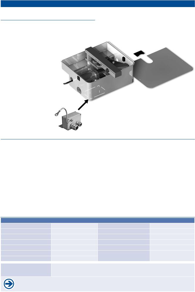
2. Installation |
Underfloor operator TURN 310 UF |
Technical layout TURN 310 UF |
|
1 |
underfloor housing |
4 |
|
|
1a |
bearing pin |
|
|
1b |
motor fastening screws (6 x) |
|
|
1c |
motor fastening nuts (4 x) |
|
|
1d |
opening for connecting cable |
5 |
|
1e |
openings for drainage |
6 |
2 |
motor-gearing unit |
7 |
|
|
2a |
grounding terminal (grounding cable laid separately) |
|
|
2b |
gearing shaft |
|
3 |
mk motor cable |
8 |
|
motor arm |
|
||
|
3a |
fastening screw |
|
|
3b |
adjustable limiting screw |
9 |
|
|
(for adjustment of gate position closed) |
|
gate driver
4a adjustable limiting hexagon
(for adjustment of gate position open) 4b fastening screw
lever arm (connects gate driver (4) with motor lever (3) ball
gate bearing
7a emergency release mechanism
7b emergency release lever housing cover
8a fastening screws (2x)
8b intakes for fastening screws (2x) plastic covering
optional: chain bracket (for turning angle > 110°)
K1 gate driver with pinion replaces (4)
K2 output pinion replaces motor arm (3)
K3 chain replaces lever arm (5)
The U-profile is not part of the delivery. It must be selected suitable to the current gate frame.
|
|
|
gate frame |
|
|
|
|
U-profile |
|
7 |
|
|
(for inserting the gate wing) |
|
|
|
|
|
|
6 |
7b |
|
optional: chain bracket |
|
|
|
7a |
|
|
|
|
|
|
|
4 |
4b |
|
K1 |
|
|
5 |
K2 |
||
|
4a |
|
|
|
|
|
3a |
|
|
|
|
|
|
|
|
|
3b |
3 |
|
|
|
2b |
|
|
|
|
|
|
|
|
|
|
1c |
|
2 |
|
|
2a |
|
|
|
|
K3 |
|
|
|
|
|
|
mk |
|
|
|
|
|
|
|
9 |
8a |
|
|
|
8 |
|
1a |
|
|
|
|
|
8b |
|
|
|
1d 
1b
1e 
1
foresee PVC-pipe Ø 60-80 for drainage!
- 4 - |
tousek / E_TURN-310UF_43000203 / 31. 08. 2016 |
HINWEIS für den Benutzer
Suggestion
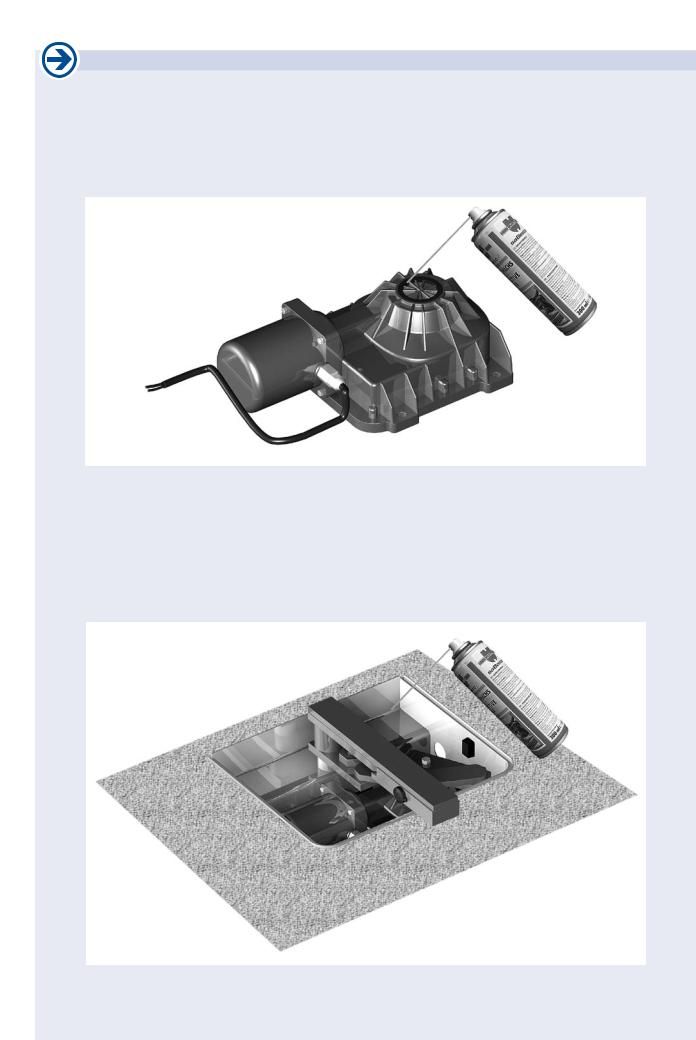
• Before mounting we suggest to spray some protection wax all around the operator.
• After mounting please spray some protection wax on all parts inside the operator housing.
tousek / E_TURN-310UF_43000203 / 31. 08. 2016 |
- 5 - |
 Loading...