

Toto TMT1NNC, TMW1NNC, TMT1LN, TMU1NNC, TMU1LN Installation Manual
Installation Manual
Manual de Instrucciones
Manuel D’Installation
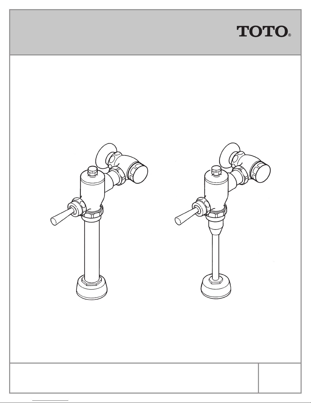
Toilet Flushometer Valves TMT1NNC, TMT1LN
Toilet Flushometer Valve TMW1NNC
Urinal Flushometer Valves TMU1NNC, TMU1LN
Warranty Registration and Inquiry
For product warranty registration, TOTO U.S.A. Inc. recommends online warranty registration. Please visit our web site
http://www.totousa.com. If you have questions regarding warranty policy or coverage, please contact TOTO U.S.A. Inc., Customer
Service Department, 1155 Southern Road, Morrow, GA 30260 (888) 295-8134 or (678) 466-1300 when calling from outside of U.S.A.
0GU3001
Rev Date: 10/10
BEFORE INSTALLATION
Prior to installing the Piston Flushometer Valve, install the items listed below:
• Closet or Urinal Fixture
• Drain Line
• Water Supply Line
The supply piping to these devices shall be securely anchored to the building structure to prevent the installed device from
unnecessary movement when operated by the user. Care shall be exercised when installing the device to prevent marring the
exposed significant surface.
IMPORTANT:
• ALL PLUMBING IS TO BE INSTALLED IN ACCORDANCE WITH APPLICABLE CODES AND REGULATIONS.
• WATER SUPPLY LINES MUST BE SIZED TO PROVIDE AN ADEQUATE VOLUME OF WATER FOR EACH FIXTURE.
• FLUSH ALL WATERLINES PRIOR TO OPERATION.
The Piston Valve is designed to operate with water pressure as low as 10psi (69kPa). HOWEVER THE MINIMUM PRESSURE
REQUIRED TO OPERATE THE VALVE IS DETERMINED BY THE TYPE OF FIXTURE SELECTED. Consult the fixture manufacturer for pressure requirements. Pressure in excess of 100psi (690kPa) is not suitable for flushing any plumbing fixture. Most
codes mandate a maximum of 80psi; Please check local code requirements.Protect the chrome or special finish of this
flushometer. DO NOT USE TOOTHED TOOLS TO INSTALL OR SERVICE THE VALVE.
INSTALLATION PROCEDURE
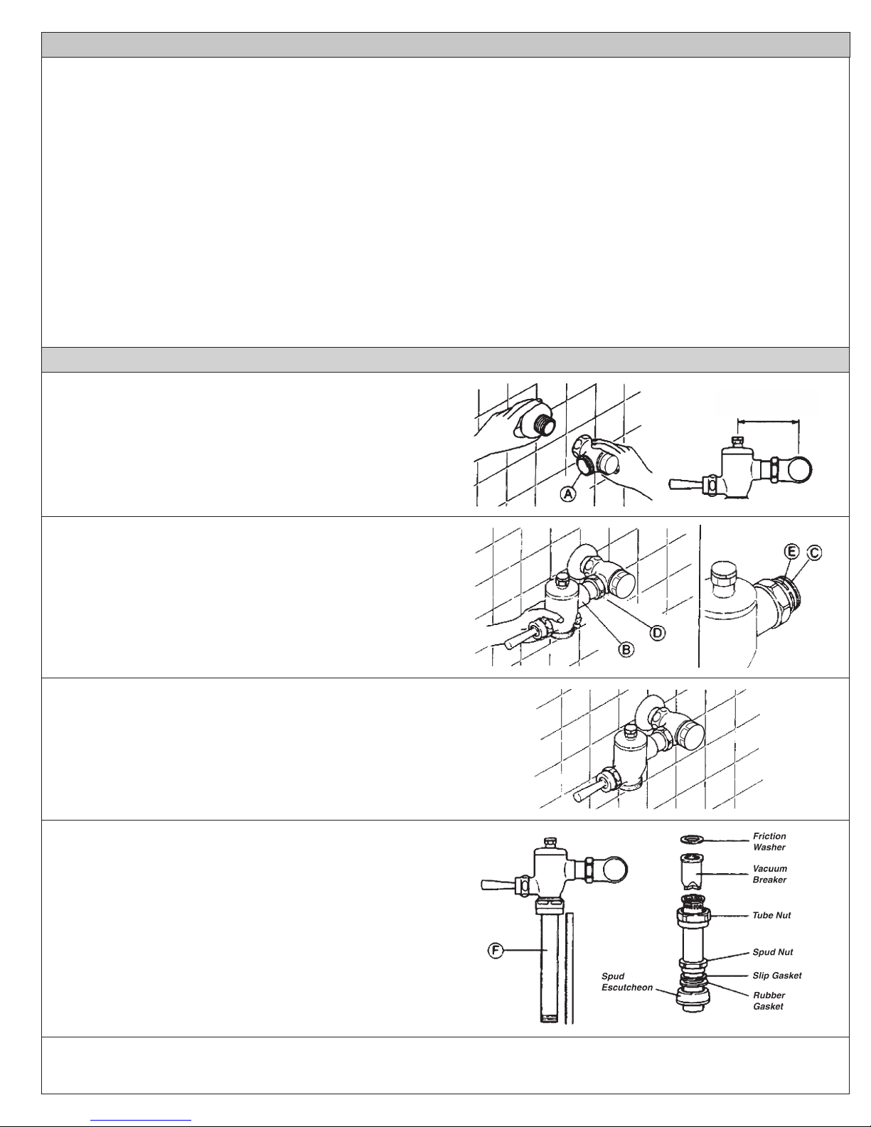
1) Install the stop valve assembly A and wall flange. Refer
to the rough in dimension shown. Thread sealing compounds should be used on the male NPT theads only.
For sweat soldering, refer to the instructions in the sweat
solder kit.
2) Prior to inserting the flushometer valve tailpiece B into
the stop valve, be certain that the O-ring seal C is located
in the O-ring seal groove at the end of the tailpiece, and
that the lock nut D and locking snap ring E are located as
shown. Care should be taken not to damage the O-ring
when inserting the tailpiece into the stop valve. If lubrication is needed, wetting the O-ring with water will be
sufficient.
3) Insert the flushometer valve tailpiece B into the stop
valve A and hand-tighten the lock nut D to the stop valve.
Plumb the entire unit.
MIN 4-1/4” (106mm)
MAX 5-1/4” (131mm)
4) Determine the length of the vacuum breaker tube F required to join the flushometer valve and fixture spud. Cut
the vacuum breaker tube, if required, to this length. Assemble the vacuum breaker tube assembly and spud nut
assembly to the flushometer valve and fixture spud.
5) Hand tighten the spud nut and the vacuum breaker tube nut to the fixture and flushometer valve. Align and plumb the valve
assembly. Tighten the fixture spud nut, vacuum breaker tube nut, and lock nut with a wrench.
2
 Loading...