

Toto TLK03001G, TLK01101G, TLK01107G, TLK01401G, TLK01403G Installation And Owner's Manual
...
Installation and Owner’s Manual
Manual de instalación y del propietario
Manuel d’installation et guide d’utilisation
Manual do Proprietário e de Instalação
Automatic Soap Dispenser
Dispensador de jabón automático
Distributeur automatique de savon
Distribuidor automático de sabonete líquido
TLK03001G TLK01101G
TLK01102G TLK01103G
TLK01106G TLK01107G
TLK01401G TLK01403G
Warranty Registration and Inquiry
For product warranty registration, TOTO U.S.A. Inc. recommends online warranty registration. Please visit
our web site http://www.totousa.com. If you have questions regarding warranty policy or coverage, please
contact TOTO U.S.A. Inc., Customer Service Department, 1155 Southern Road, Morrow, GA 30260
(888) 295-8134 or (678) 466-1300 when calling from outside of U.S.A.
TABLE OF CONTENTS
THANK YOU FOR CHOOSING TOTO! ............................................................................................2
WARNINGS....................................................................................................................................... 2
BEFORE INSTALLATION .................................................................................................................2
INCLUDED PARTS ...........................................................................................................................3
INSTALLATION PROCEDURE......................................................................................................... 5
TESTING......................................................................................................................................... 16
HOW TO USE .................................................................................................................................17
ENGLISH
REFILLING THE TANK ...................................................................................................................18
MODE ADJUSTMENT.....................................................................................................................19
CARE AND CLEANING ..................................................................................................................20
PERIODIC MAINTENANCE............................................................................................................ 21
LONG-TERM NON-USE .................................................................................................................25
TROUBLESHOOTING ....................................................................................................................25
SPECIFICATIONS...........................................................................................................................26
THREE YEAR LIMITED WARRANTY............................................................................................. 28
ROUGH - IN DIMENSIONS...........................................................................................................110
THANK YOU FOR CHOOSING TOTO!
The mission of TOTO is to provide the world with healthy, hygienic and more comfortable lifestyles.
We design every product with the balance of form and function as a guiding principle.
Congratulations on your choice.
WARNINGS
Please read and adhere to the following notes. Failure to do so could result in personal injury
and/or property damage.
No person other than a service engineer should disassemble, repair or modify this
dispenser, unless it is specifically described in this manual. Failure to do so may result in
electric shock or product malfunction.
Do not use this dispenser in a humid location where condensation may collect on the
surface, especially in a sauna or steam room.
Do not strike or kick the dispenser or controller box, as this may damage the unit or cause a leak.
Do not use this dispenser if the room temperature drops below freezing.
Make sure the power cord does not come in contact with the hot water supply line.
Avoid placing any objects within the detection range of the infrared sensor.
Use only TOTO approved liquid soap to avoid invalidation of warranty.
Make sure the electrical outlet is in a position where it will not get wet during use.
BEFORE INSTALLATION
Read these instructions carefully to ensure proper installation.
TOTO reserves the right to update product design without notice.
Check to make sure you have the parts indicated on the following page.
2
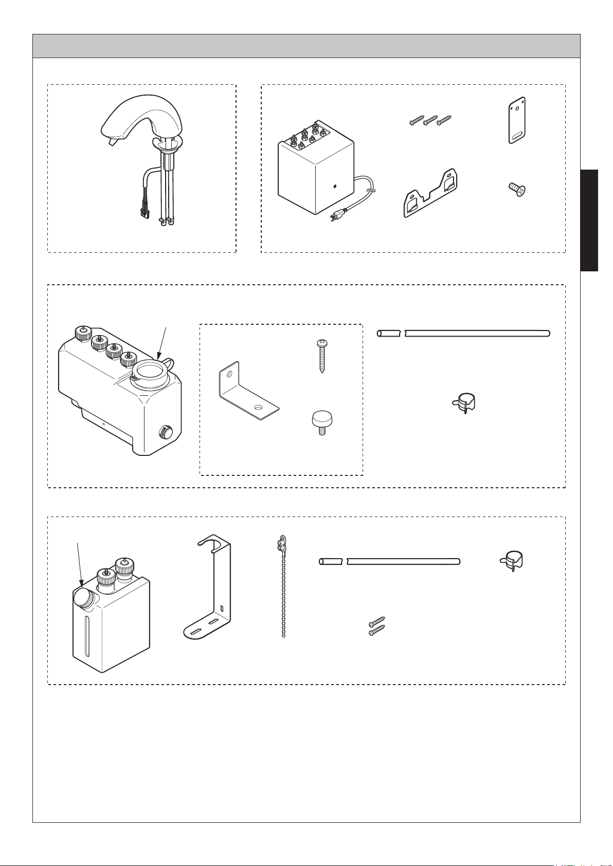
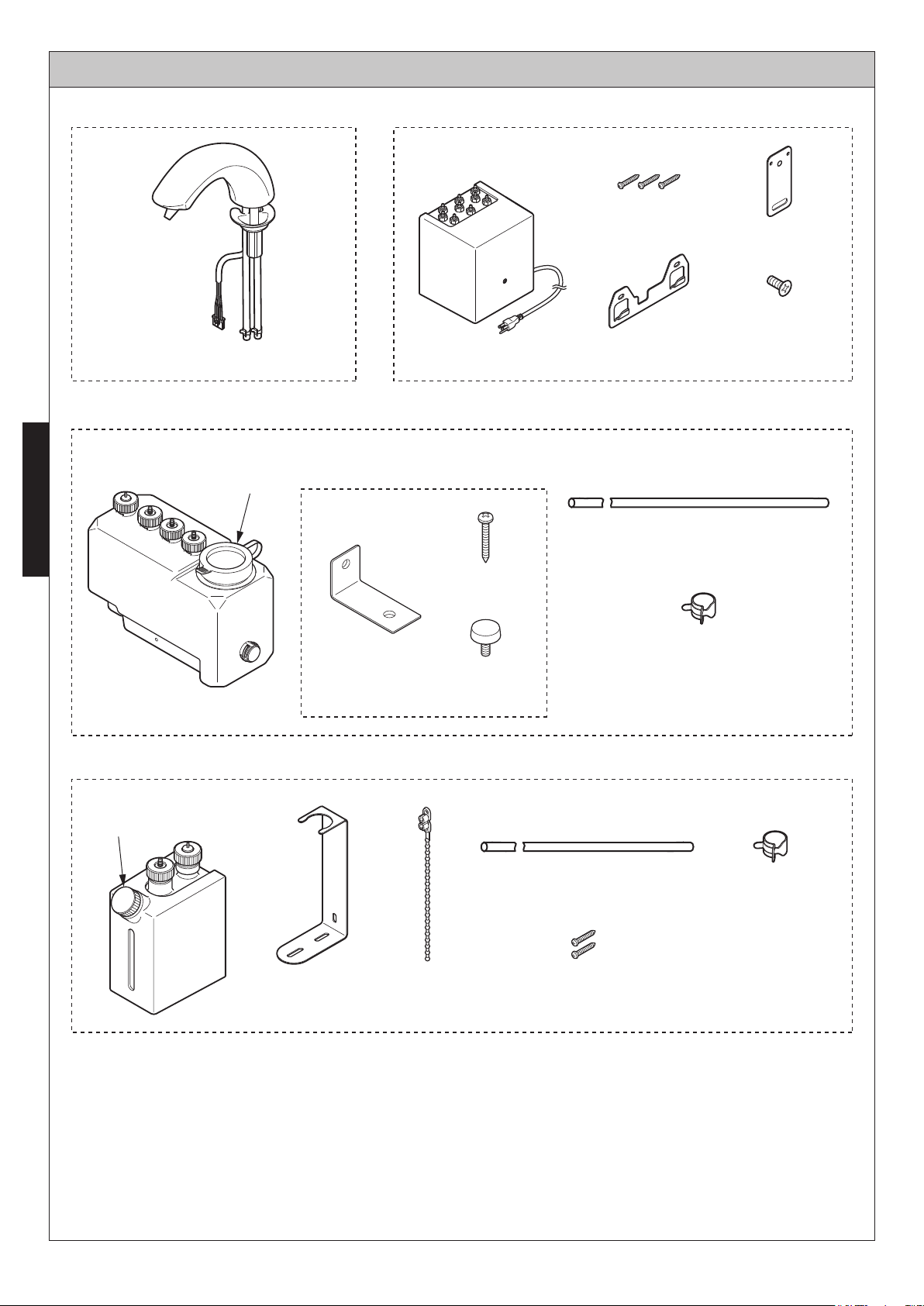
(TLK03001G)
Supply port cap
INCLUDED PARTS
3L tank
Bracket set
(for 3L tank only)
ControllerSpout Assembly
(Φ 5.1 x 32)
Mounting
bracket
Screw
Anchoring plate
Countersunk
tapping screw
(Φ 4 x 10)
ENGLISH
Supply port cap
Screw
(Φ 5.1 x 32)
Bracket
Decorative
screw
*1L tank (Special Order)
(Single type: 1, Double type: 2,
(Single type: 2, Double type: 4,
Hose 7.1” (18 cm)
Hose 6.6’ (2 m)
Triple type: 3)
Hose clamp
Triple type: 6)
Hose clamp: 2
Bracket
Bundling
band
Round-head screw
(Φ 5.1 x 32)
3
ENGLISH
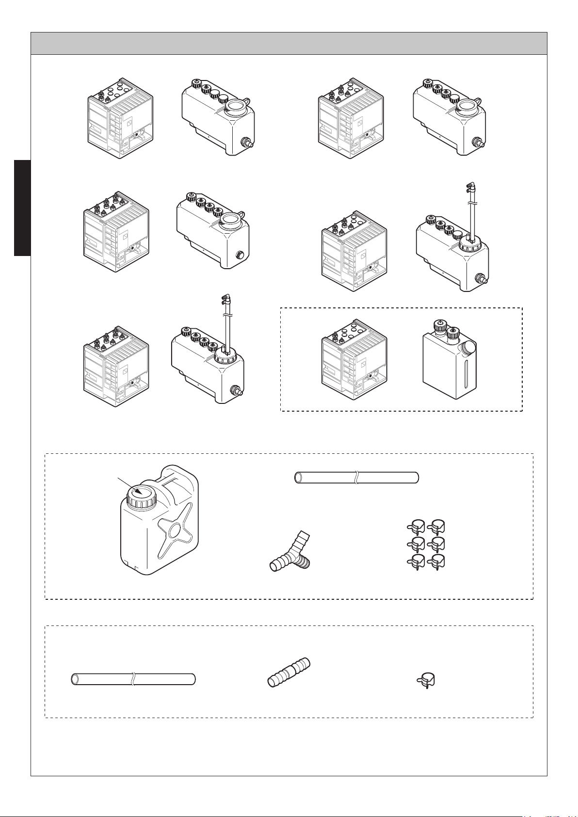
INCLUDED PARTS
TLK01101U TLK01102U
TLK01103U
(Continued)
TLK01106U
Soap Intake
TLK01107U
Special Order
Sub-Tank Unit (TLK01401U)
Connecting hose 16.4’ (5m)
Sub-Tank Y-shaped nipple
Hose Unit (TLK01403U)
I-shaped nippleConnecting hose 16.4’ (5m) Hose clamps (1)
4
Hose clamps (6)
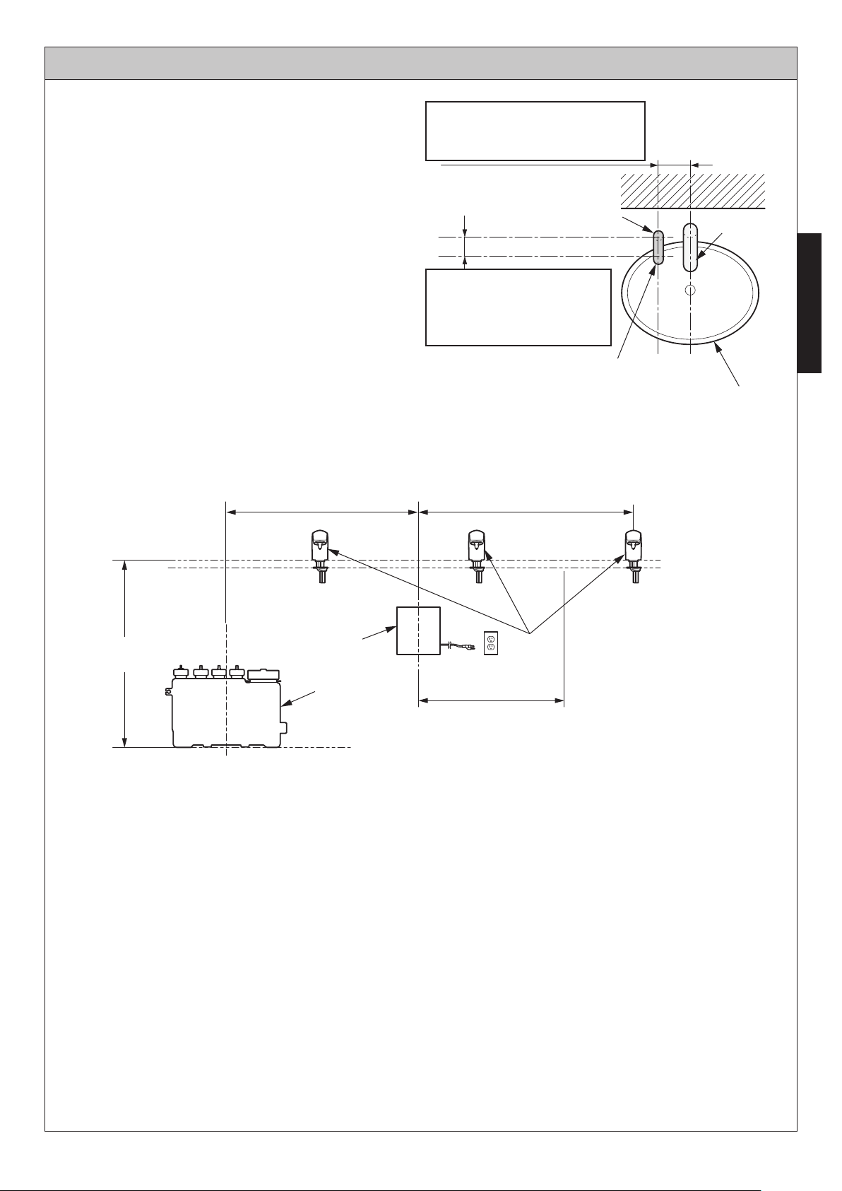
INSTALLATION PROCEDURE - Positioning
Positioning the Dispenser
1. Make sure to leave at least 4-3/4" (120 mm)
of space between the soap dispenser and
the faucet to prevent accidental activation.
2. Leave 3-1/8" (80 mm) of space maximum
from the inside edge of the sink to the spout
installation hole to ensure that any residual
soap drips from the dispenser spout into the
sink bowl.
Positioning the Tank
(1) Space between the dispenser
and the faucet to be
4-3/4" (120 mm) minimum
Hole for installing
the dispenser
[1"~1-3/32" (25~28 mm)
in diameter]
(2)
The distance from the
soap dispenser to the
edge of the sink to be
3-1/8" (80 mm) maximum
Auto Soap Dispenser
Less than 55'' (1400 mm)
(Height of controller:
14'' (350 mm))Less than 59'' (1500 mm)
Faucet
ENGLISH
Sink
(Unit: Inch)
Less than 31.5''
(800 mm)
Controller
Tank
Controller installable range
(* 59'' (1500 mm))
* The dimensions in the figure are limited to when
the tank is installed on the left end.
If actual dimensions exceed those in the figure,
cords and hoses may not reach.
Spouts
* For a spout-to-spout distance
of 25.6'' (650 mm)
Install the tank within 31.5 inch from the upper face of the counter. It also should not exceed the
height of the upper end of the controller.
It cannot be installed on the counter or on the lower level.
If it is installed beyond this range, the following troubles may occur. Less water spouts and the
soap does not foam.
The length of the hose connected to the spout is 6.0 ft. Install the controller so that the hose can
be connected to the controller.
5
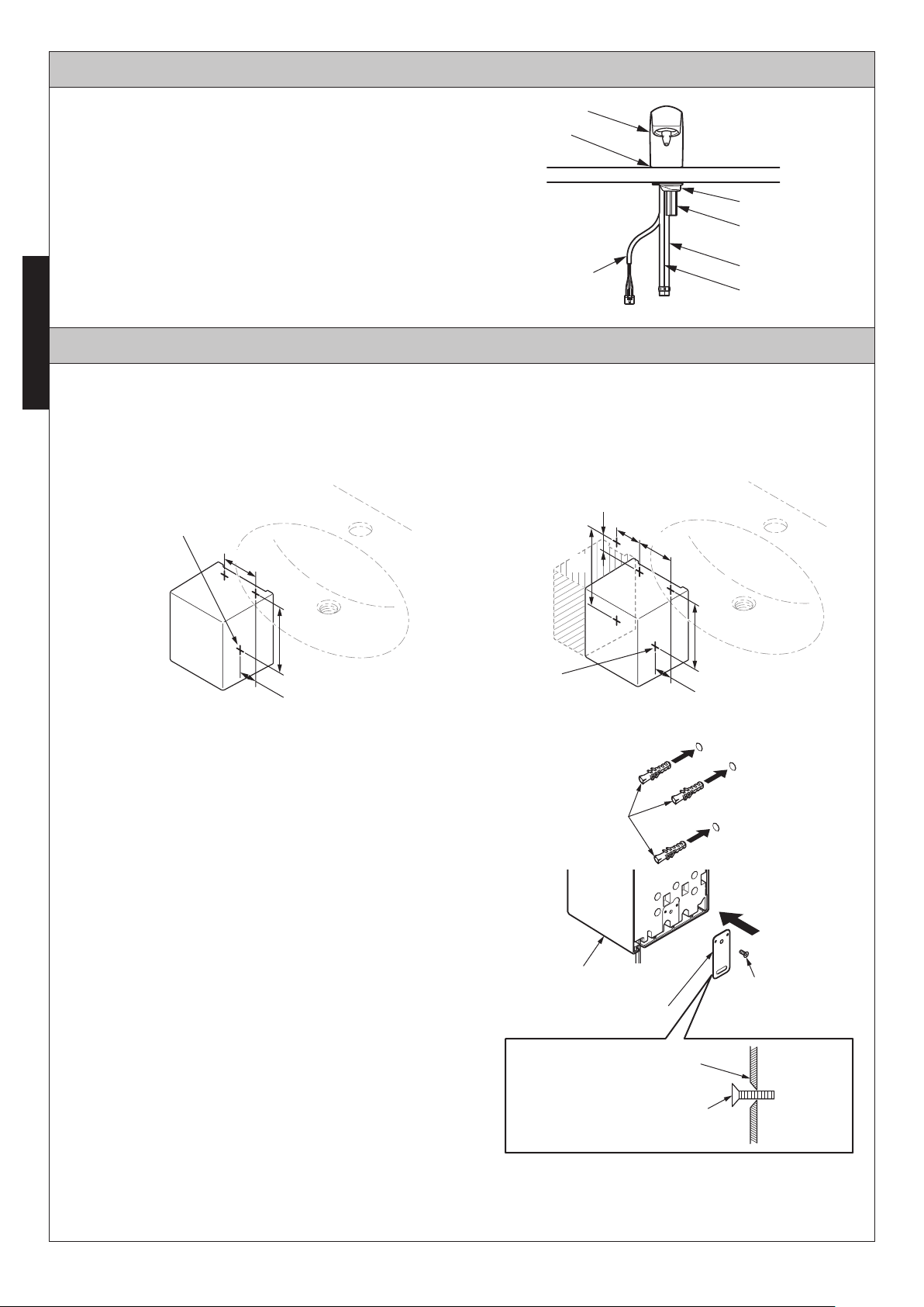
INSTALLATION PROCEDURE - Spout
1. Insert the dispenser into the installation
holes in the counter (or the sink).
Dispenser
Packing
2. Disassemble screw and washer with the
hex nuts.
Caution
Make sure that the cords and tubes do not get
crimped.
ENGLISH
Sensor cord
Washer
Hex nut
Air hose (blue)
Liquid soap hose
(clear)
INSTALLATION PROCEDURE - Controller
Marking of the positions of the screw holes for the anchoring plate.
Decide the anchoring position of the controller and mark the positions of screw holes on the wall by
referring to the dimensional drawing.
[ 3L Tank Type ]
Reference
anchoring screw
3.7''
[ 1L Tank Type ]
0.8''
5.4''
2.8''
3.7''
(Unit: Inch)
5.9''
1.9''
Reference
anchoring screw
Installing the controller on a tiled or concrete wall
1. Drill a rough hole at the screw hole position
and drive in the curl plug (procure in the field).
* Procure a curl plug that matches the screw
(Φ 5.1 x 32).
2. Anchor the bottom anchoring plate to the
controller with one countersunk tapping screw.
Caution
Do not tighten the screws with an electric
screwdriver.
These should be tightened manually.
Pay attention not to confuse the top side and
the bottom side of the anchoring plate.
Controller (Back side)
Anchoring plate
5.9''
1.9''
Anchor
Countersunk
tapping screw
(Φ 4 x 10)
Anchoring plate
Countersunk tapping screw
(Φ 4 x 10)
Top side Bottom side
6
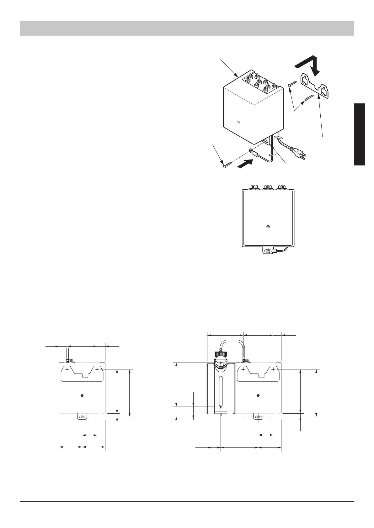
INSTALLATION PROCEDURE - Controller
3. Position and anchor the bracket with two
screws.
4. Hang the controller on the mounting bracket
and anchor the bottom anchoring plate with
one screw.
*
Sandwich the grounding wire with the
mounting bracket and anchor them with screw.
(Continued)
Controller
Screws
Screw
Installing the controller on a wooden
wall or dry wall
Confirm that the wooden wall has a structure that
can sustain the weight (4.41lb) of the controller
(Triple type). (In the case of dry wall, in order to
hold the controller, make sure the plywood base
is more than 0.5 inch thick.) Anchor the mounting
bracket with two screws and anchor the anchoring
plate with one screw. Reinforce the wall structure
sufficiently as needed.
Caution
Install the unit body horizontally.
Pay attention not to pinch of the electric cord or
contact it with edges.
Dimensions
[ 3L Tank Type ] [ 1L Tank Type ]
Mounting bracket
ENGLISH
Anchoring plate
(Unit: Inch)
1.0'' 1.0''3.7''
2.8'' 2.8''
1.9''
5.4''
0.4''
5.9''
5.4''1.3''
4.5'' 3.7'' 1.0''
0.8''
1.7'' 2.8''
4.6''
7
1.9''
5.4''
0.4''
5.9''
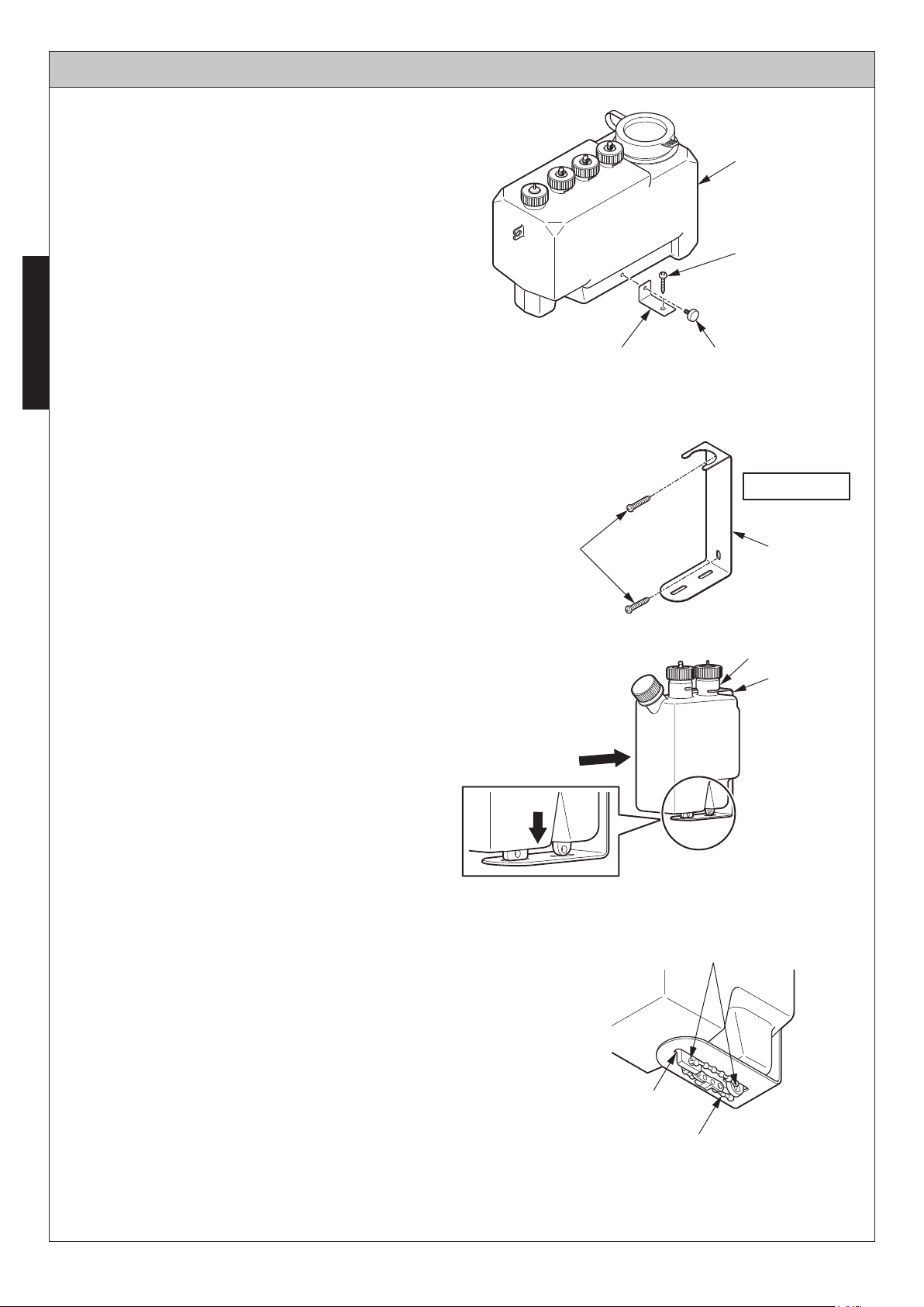
INSTALLATION PROCEDURE - Tank
[ 3L Tank Type ]
Using the bracket to anchor the tank on the floor.
1. Anchor the tank and the brackets with the
decorative screws that should be tightened by
hand.
Tank
2. Install the tank on the floor with the screw.
ENGLISH
Note
If the floor is made of concrete, embed the curl
plugs first.
[ 1L Tank Type ]
1. Anchor the bracket with the attached
round-head screw.
2. Pass the constricted part of the tank
between the bracket and insert it the full
depth.
Two round-head
screws
(Φ 5.1 x 32)
2. Screw
Bracket 1. Decorative screw
Wall surface
Bracket
Constricted part
Bracket
3. Insert the tank in the slit on the bottom
surface of the bracket and pass it through
the two holes.
4. Attaching the bundling band.
* The bundling band serves to prevent the
tank from falling off if the tank collides
with something.
If the tank is installed behind a wall, etc., it
is not necessary to attach the bundling
band.
2. Insert it
the full depth.
3.
Hole
Slit on the bottom of
the bracket
4. Bundling band
8
INSTALLATION PROCEDURE - Connecting Hoses and Cords
Hose Connections
1. Cut the hoses to an appropriate length that
reaches to the connected part.
(Between the spouts and the controller)
(Between the controller and the tank)
Caution
Using a cutter, etc., cut the hoses so that the
cut surface becomes vertical.
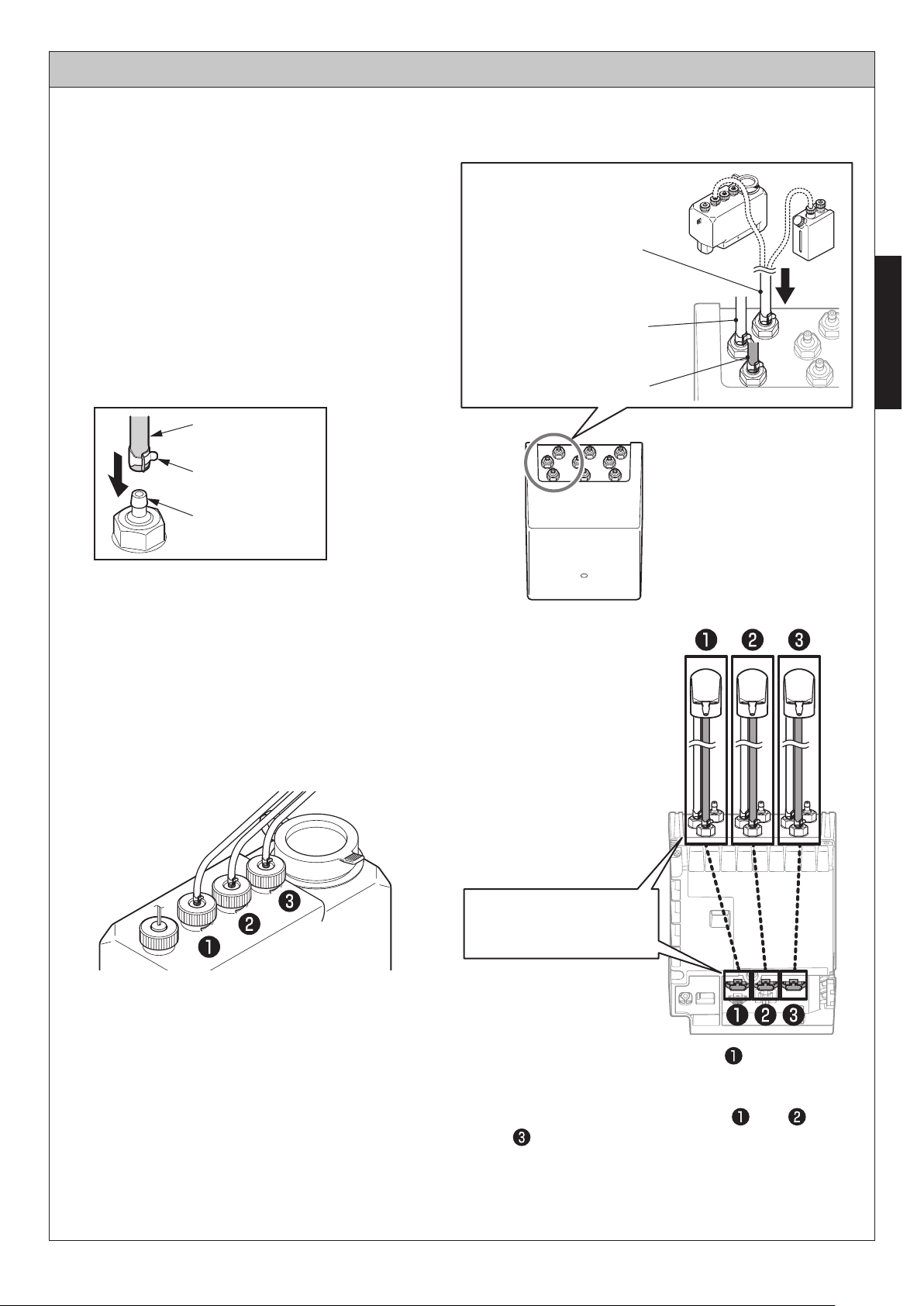
2. Insert the hose fully into the controller and
put the hose clamp on the projection of the
joint to anchor the hose securely.
Hose
Hose clamp
Projection of joint
Caution
Connect the hoses and sensors in the
predetermined pairs.
When inserting the hoses, pay attention not
to apply strong force to the joint of the tank.
Pay attention not to bend the hoses.
[ Controller side ]
Liquid soap hose (clear)
Connect it to the tank.
Liquid soap hose (clear)
Connect it to the spout.
Air hose (blue)
Connect it to the spout.
3L TANK 1L TANK
ENGLISH
[ Tank side ]
Connect the hoses
and sensors in the
predetermined pairs.
* Connect the single type to only.
(The sensor does not work in any other
position.)
* Connect the double type to and .
( does not work.)
9
INSTALLATION PROCEDURE - Connecting Hoses and Cords
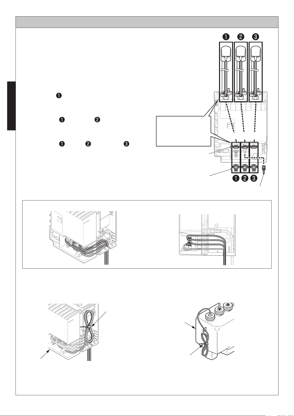
Connector Connections
Remove the cover of the controller and
connect the sensor connector to the float
switch connector.
Connect the sensor connector and the hose
in the prescribed positions.
For single installation
Connect in one place.
ENGLISH
Connector (white) for sensor only
For double installation
Connect in two places.
Connectors (white) and (yellow) for sensor
For triple installation
Connect in three places.
Connectors (white), (yellow) and (blue)
for sensor
Caution
All connectors of the sensors connected to the
spout are white.
The colors of the connectors arranged in the
controller are white, yellow and blue.
Different colors may be connected.
Connect the hoses
and the sensors in
predetermined
pairs.
Socket (Sensors)
Connector (Sensors, white)
(Continued)
White Yellow Blue
Float switch
Wiring Image
Side face (View of wiring)
Bundling of Cords
Using bundling clamps, stow and bundle the cords.
[ Sensor cord ] [ Float switch cord ]
Bundling clamp
Tank
Controller
Bundling clamp
10
INSTALLATION PROCEDURE - FILLING liquid soap
1. Remove cap on the tank.
2. Slowly pour liquid soap into the holding tank.
Please keep an eye on the level as you pour the
liquid soap in slowly so that it doesn't become
foamy. Please pour the liquid soap through the
build-in filter.
Open
ENGLISH
3. Firmly close the cap on the tank.
Please make sure that the cap is securely in place
after filling the tank.
Close
11
ENGLISH
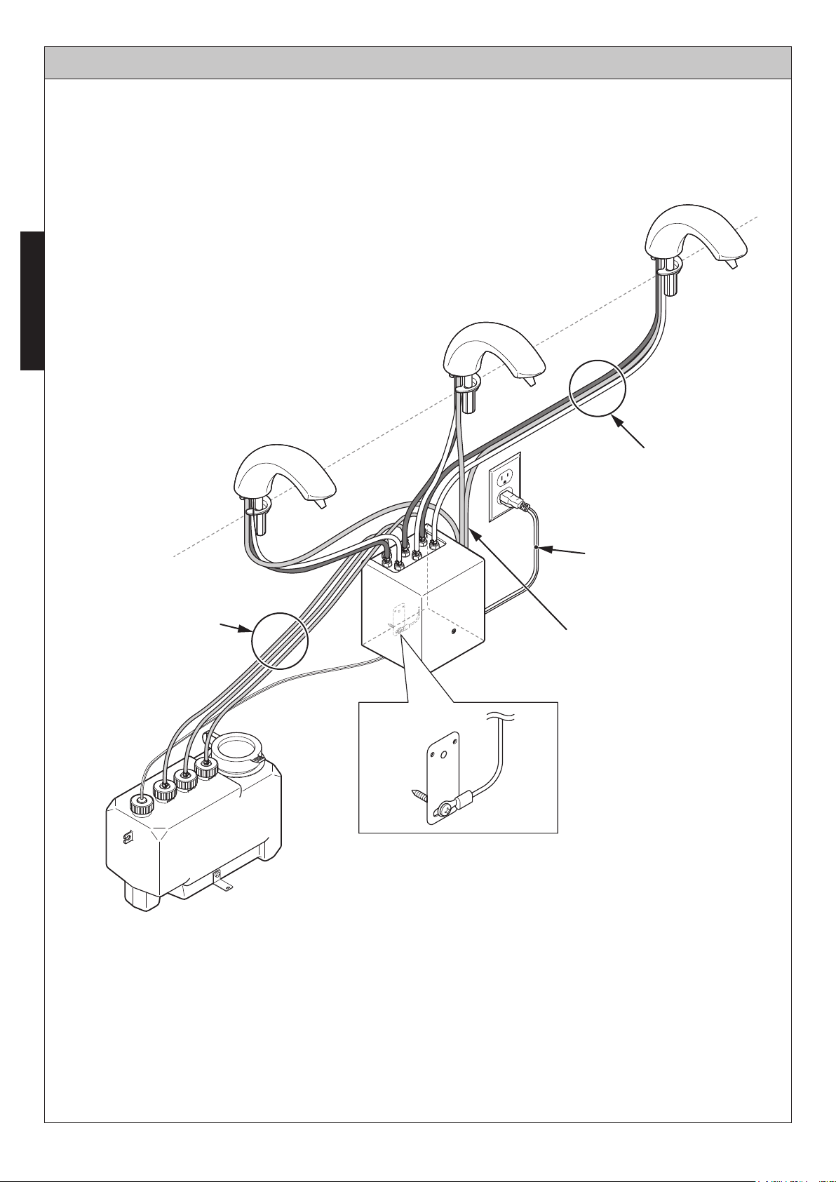
Installation Completion Drawing
L=6ft (1800mm)
L=6.6ft (2000mm)
L=4.6ft (1400mm)
Bundling of cords
12
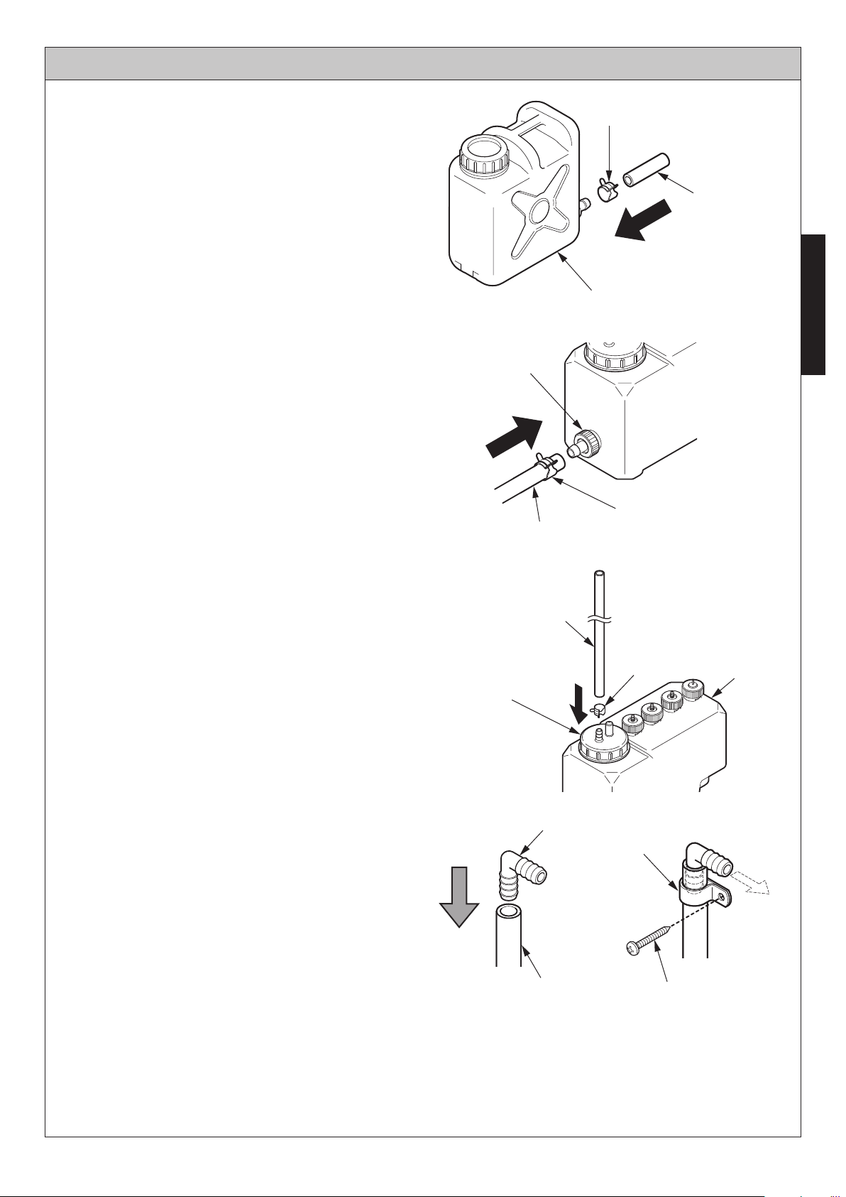
INSTALLATION PROCEDURE - Sub Tank Unit
1. Connect the hose to the sub-tank.
* Use the connection hose for connecting
the tank and cut to the desired length to fit
between the sub-tank and the tank.
Caution
Do not have kinks or excessive bends in the
hose.
Check that all cap nuts are tight.
If loose, liquid leaks.
Check them periodically.
2. Connect one end of the connection hose to
the coupling cap on the side of the tank.
Caution
Be sure to tighten the hose connection with the
hose clamp to secure it into place.
Hose clamp
Connection
hose
Sub-tank
ENGLISH
Check
Hose clamp
Connection hose
3. Connect the air deflation hose.
Caution
Be sure to tighten the air deflation hose
securely with the hose clamp.
4. Attach the elbow to the front end of the air
deflation hose and attach it to the wall with
the hose tie and wood screw.
* Do not block the elbow. It is the air bleed
point for the system. The soap will not
flow properly if the elbow is blocked.
Be sure to install the elbow between the
top of the sub-tank and the counter.
When the elbow is installed lower than
the sub tank the soap overflows.
Be sure that the hose tie is in position with
the air deflation hose and the elbow.
Air deflation hose
Check
Elbow
Air deflation hose
Hose clamp
Hose tie
Wood Screw
Tank
Air
13
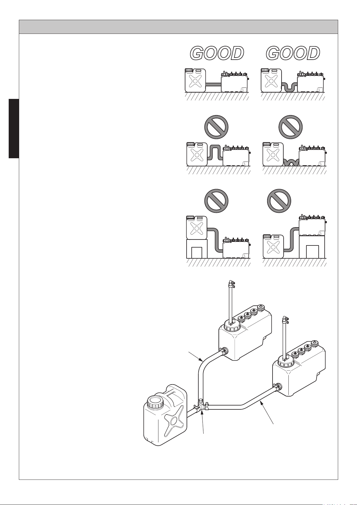
INSTALLATION PROCEDURE - Sub Tank Unit
The total length of the connection hose is
16.4′ (5 m).
To ensure sufficient supply performance, do
not use a hose that is longer than 16.4′ (5
m).
Please install the hose horizontally.
ENGLISH
Install the hose in a straight line.
A bent hose will prevent the smooth flow of
liquid soap.
Position the tanks on a level surface at even
height. Installing the tanks at different levels
may result in the following malfunctions:
(Continued)
GOOD GOOD
Soap leakage from the tank that is at a
lower level.
Improper detection of the liquid soap level
in the tank at the higher level.
Up to two tanks can be connected to one
sub-tank. Attach the Y-shaped nipple to
sub-tank to divert the connection hoses and
connect them to each of the tanks.
Note
Hose length max 16.4′ (5 m)
Connection hose
14
Connection hose
Y-shaped nipple
Sub-tank supply
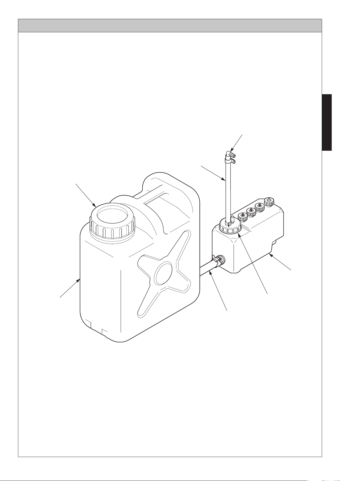
Installation Completion Drawing
Elbow
ENGLISH
Air deflation hose
Sub-Tank
Tank
Coupling Cap
Connection hose
15
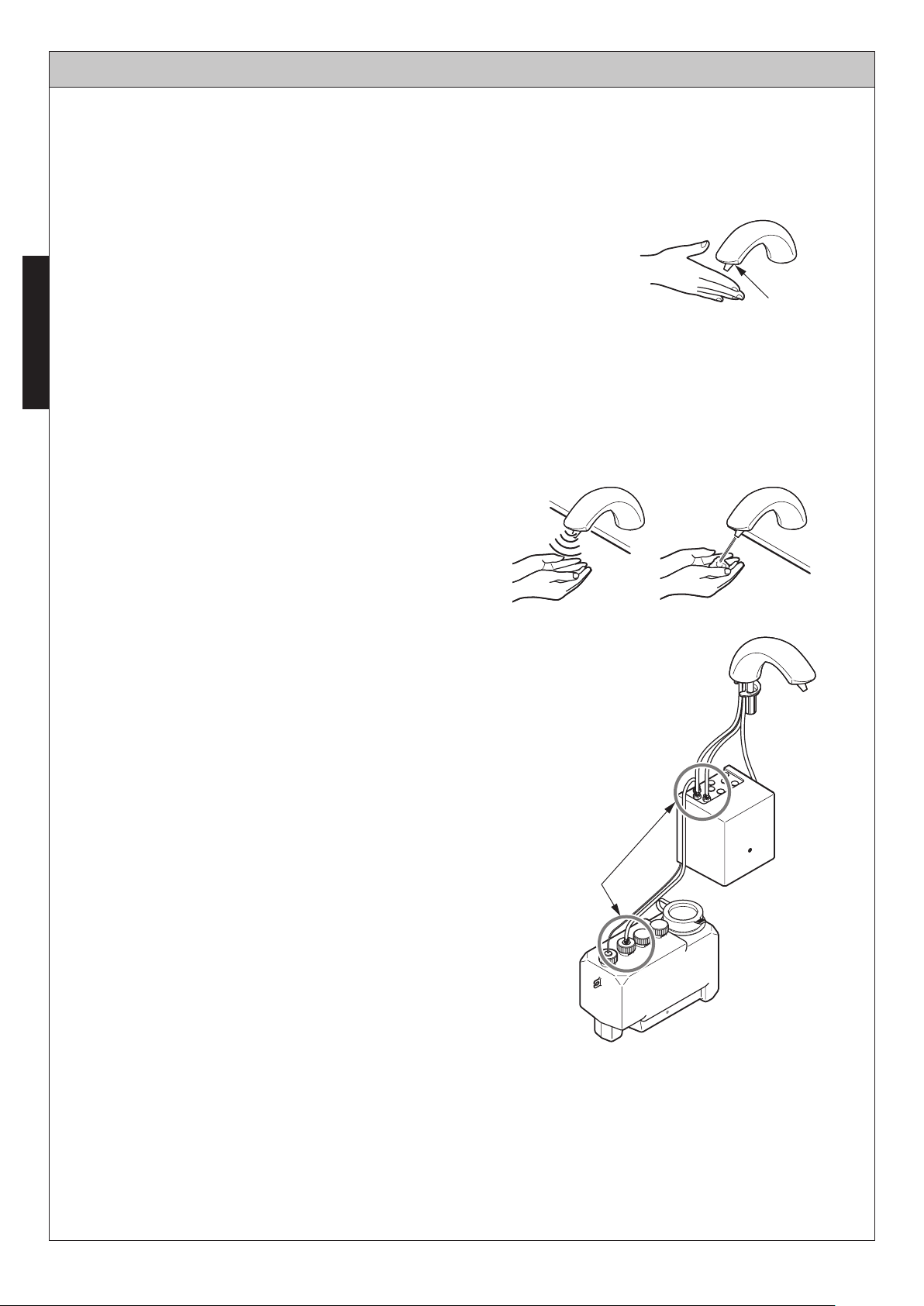
TESTING
After installation is complete, confirm that the dispenser is working properly using the following method.
Checking after the completion of installation.
After the installation has been compleated, test the product using the following procedure.
1. Shift the mode to the installation checking mode.
When your hand is held under the sensor for about 8 sec during
the first 10 minutes after the power is turned on, the mode shifts
ENGLISH
to the “Installation Mode”.
During sensing, the liquid soap pump is driven and the liquid
soap continues to come out. (30 sec at maximum)
The liquid soap stops when your hand leaves the sensor.
Use this function for filling an empty flow path with liquid soap.
Sensor
Caution
If more than 10 minutes pass since the power was turned on, pull out the power plug and insert it
again.
When disconnecting and reconnecting the power plug , pull out the power plug and leave it
unplug for longer than 10 sec.
2. Dispense and stop the liquid soap.
The liquid soap comes out when you bring
your hand under the sensor.
The liquid soap stops when your hand
leaves the sensor.
3. Check the tank and the connection of the
liquid soap hose for any liquid soap leaks.
Checking for leaks
Caution
If the product is not used for a long period of time after installation, liquid soap remaining in the
hose dries and dispenses poorly. Therefore, conduct the trial run with water.
After the trial run, leave water accumulated in the tank as is and replace it with liquid soap at the
beginning of actual use.
16
HOW TO USE
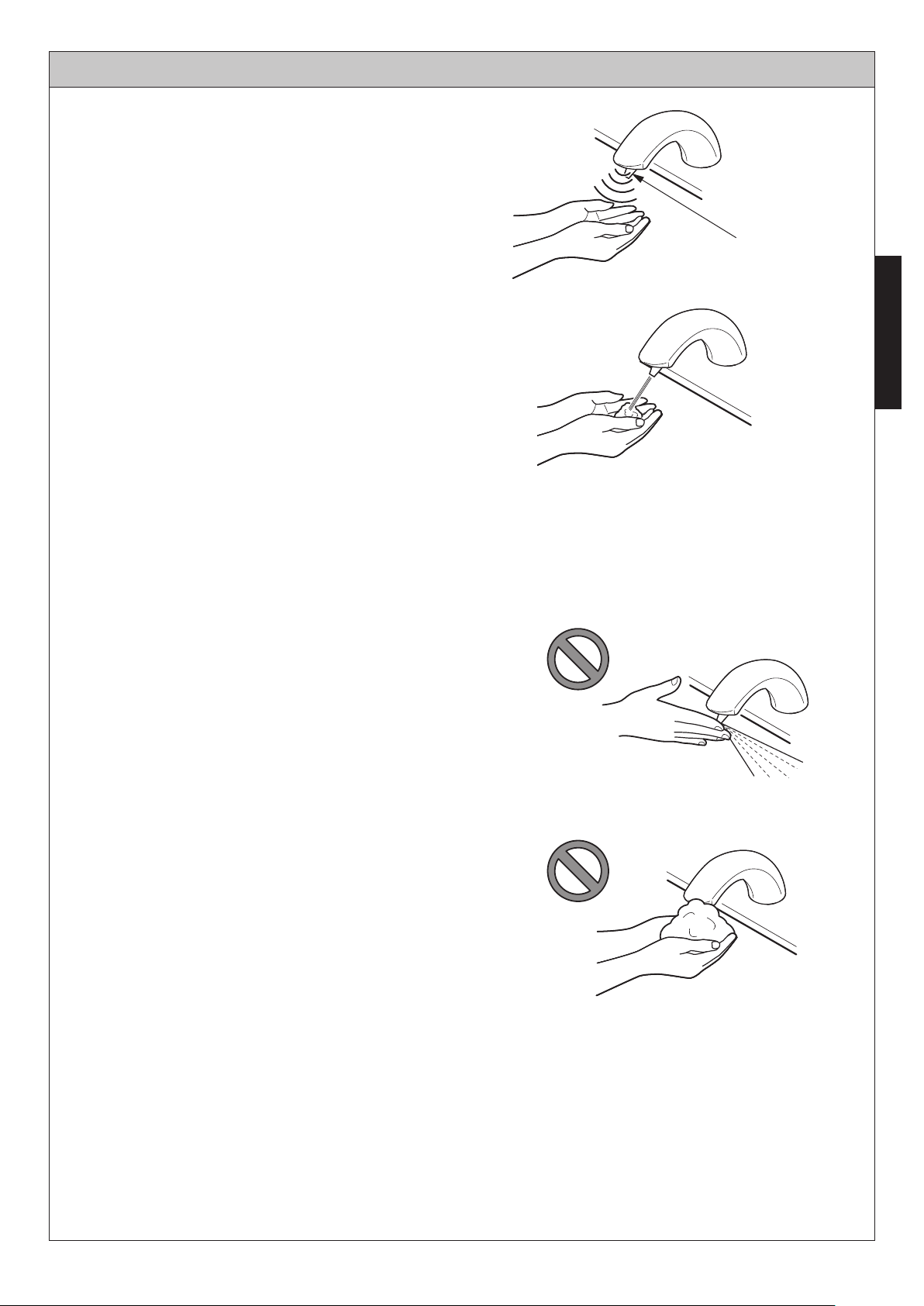
Place Hands Under Dispenser Spout.
When the sensor senses someone’s hands, it
dispenses a mousse-like liquid soap.
The dispensing time is approximately 0.5 second.
Dispensing stops when the hand is taken away
from the dispenser.
If one’s hands remain in front of the dispenser,
the mousse-like liquid soap will again be
dispensed after approximately a 3 seconds delay.
This process can be repeated up to three times.
In order to prevent misuse, the liquid soap
dispenser will stop dispensing after 3 times, but
repeated soap dispensing is possible by moving
the hands away and placing them in front of the
dispenser again.
*
This function does not work for the first 10 min.
after the power is turned on.
(See page 16 "Installation Mode")
Please do not obstruct the dispenser spout
opening.
The soap might fly off in an unexpected direction.
Dispenser Spout
ENGLISH
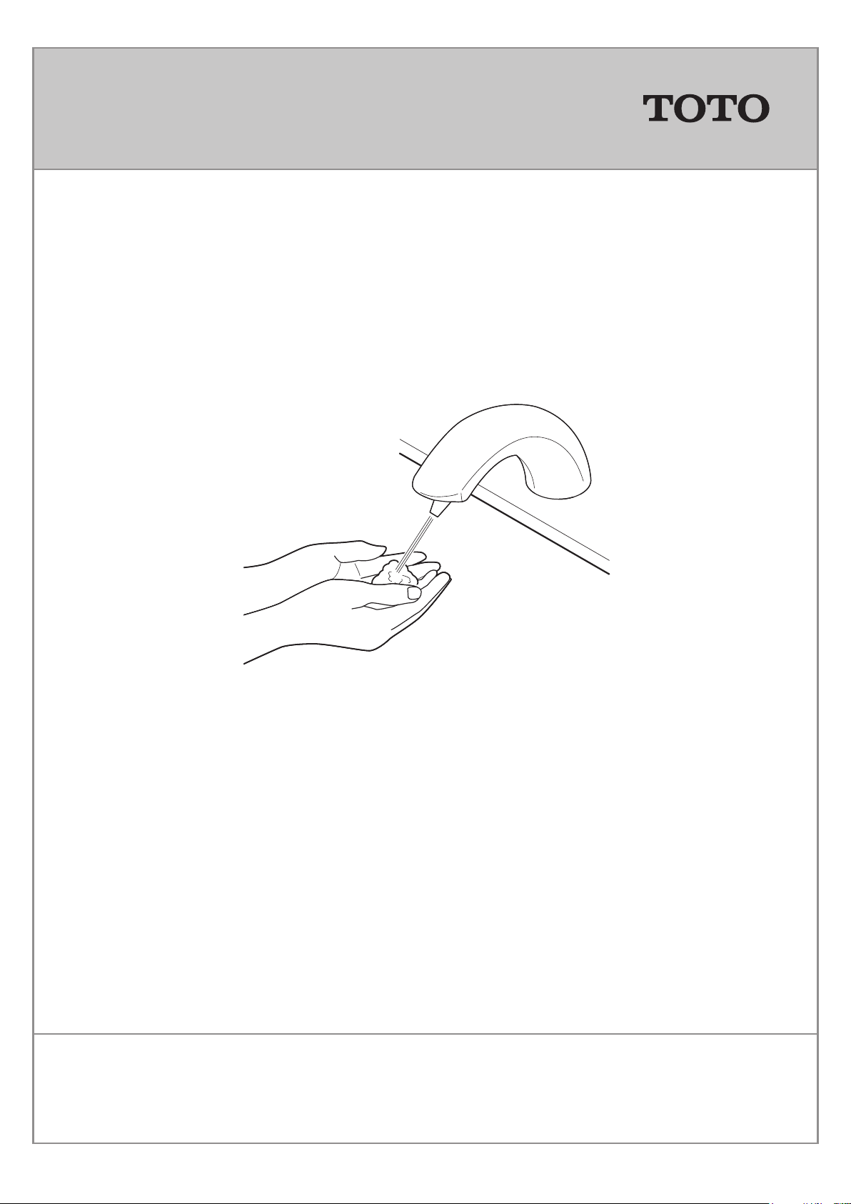
Please do not put foam on the tip of the
dispenser. If the sensor is blocked, it could
malfunction.
When the tip is blocked , please wipe away the
debris using a damp cloth.
17
REFILLING THE TANK
Please refill the tank with liquid soap when the internal sensor lamp (red) starts blinking.
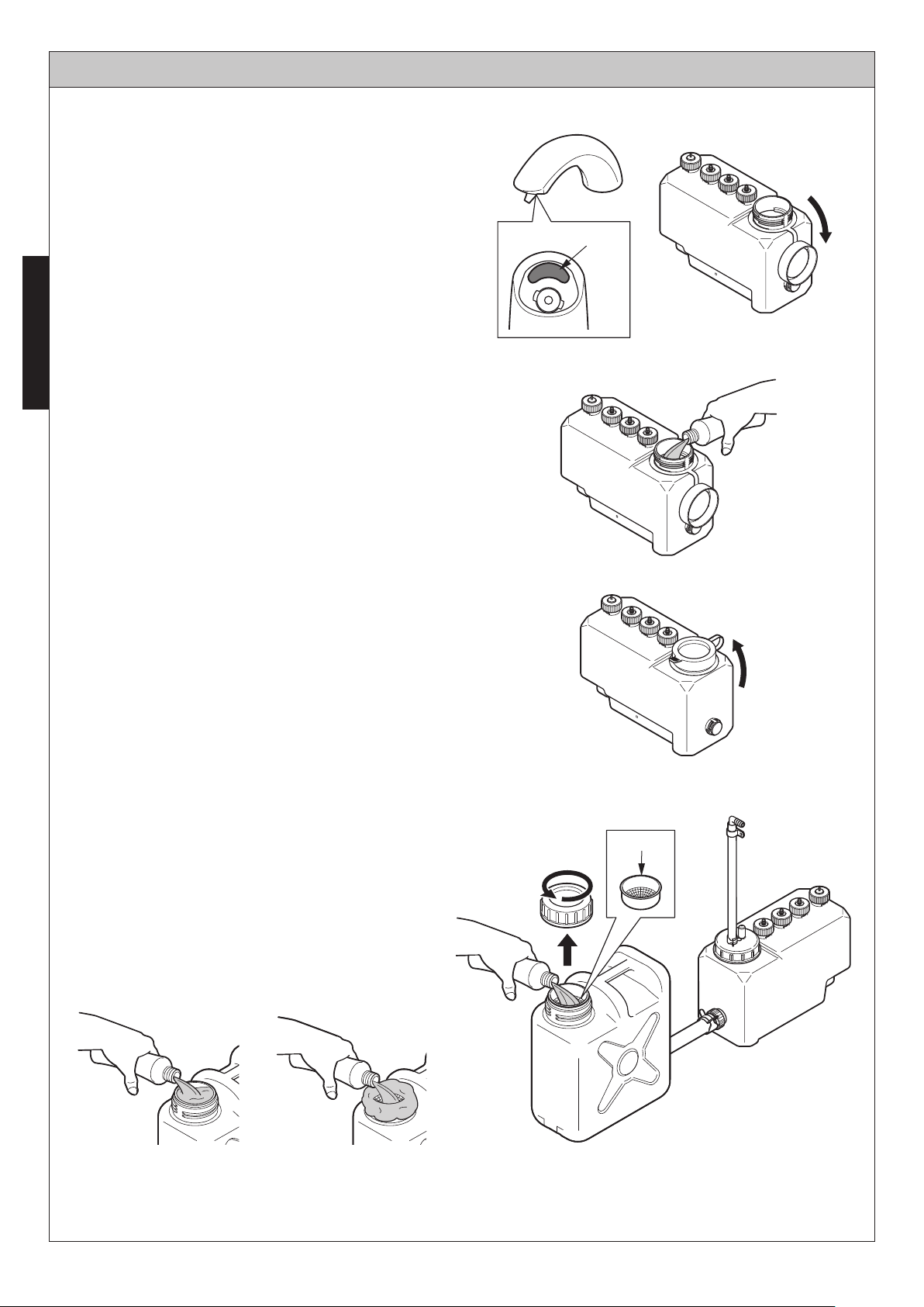
1. Remove the cap on the tank.
Sensor
ENGLISH
2. Slowly pour the liquid soap into the holding
tank.
Please keep an eye on the level as you
pour the liquid soap in slowly so that it
doesn’t become foamy. Please pour the
liquid soap through the built-in filter.
Open
3. Firmly close the cap on the tank.
Please make sure that the cap is securely
in place after filling the tank.
Filling the Sub-Tank (Only if a sub-tank has been installed.)
When a sub-tank has been installed, please fill
the liquid soap from the opening in the sub-tank.
Note
Pour soap slowly to avoid bubbles in the tank.
If the soap is very slow to drain into the
tank where excessive bubbling occurs,
please clean the filter and cap area.
Close
Filter
18
MODE ADJUSTMENT
Setting the Dispensing Volume of Liquid Soap
The dispensing volume of liquid soap has been adjusted to 0.04 o.z before shipping from the factory.
This volume can be changed to 0.06 o.z by pulling out the connector.
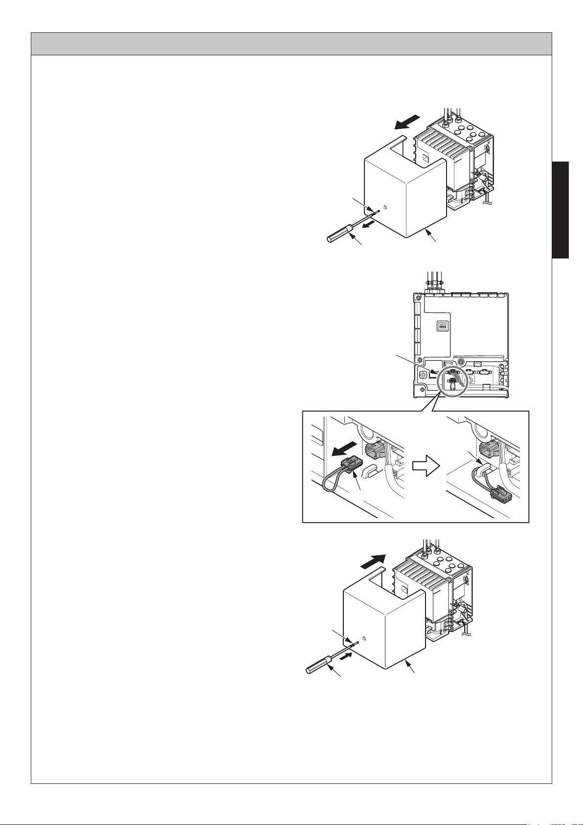
1. Remove the controller cover.
Screw
Screwdriver
2. Remove the connector cord from the hook.
3. Pull out the connector.
Controller cover
ENGLISH
4. Hang the connector on the hook.
(To prevent loss)
5. Mount the controller cover.
Caution
Tighten the screws securely.
If water is splashed over the tank, the water can
penetrate into the controller and cause damage.
Note
If the connector is connected again, the liquid
soap dispense volume is reset to 0.04 o.z.
Screw
Screwdriver
Connector
Hook
Connector
Pay attention not to
pinch the cord.
Controller cover
19
CARE AND CLEANING
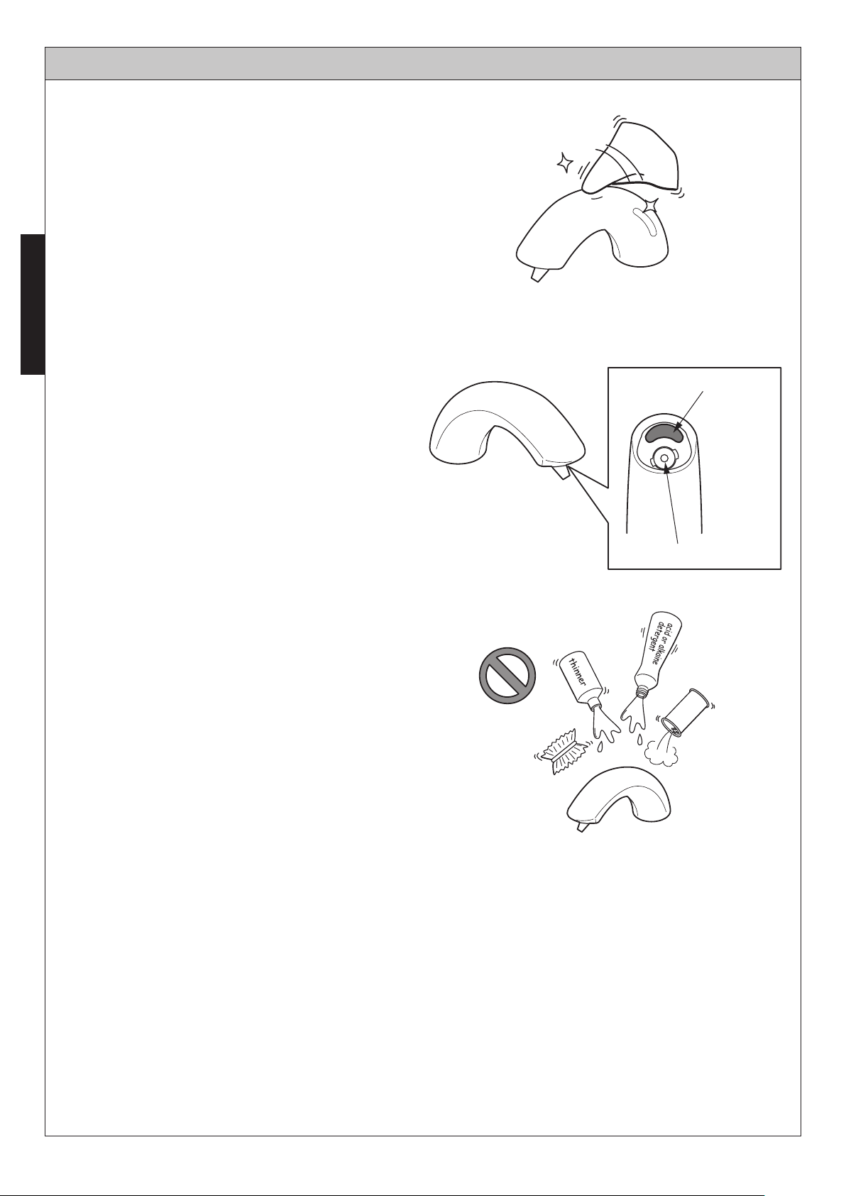
For Light Cleaning
Please use a cloth that has been soaked in water
and wipe away any debris adhering to the
dispenser or sensor.
For Heavy-Duty Cleaning
After wiping away debris with a cloth containing a
ENGLISH
suitable amount of a neutral, dishwashing
detergent, wipe clean with a damp cloth.
When cleaning around the sensor, please be
careful not to scratch the surface of the sensor.
Please avoid using cleansers that might scratch
the surface of dispenser.
These include:
Detergents containing acid, chlorine bleach or
alkali.
Solvents like paint thinner or benzene.
Detergents with coarse granules, polishing
powder or cleanser. Nylon scrubbers, pot
scrubbers, brushes, etc.
Sensor surface
Dispenser spout
20

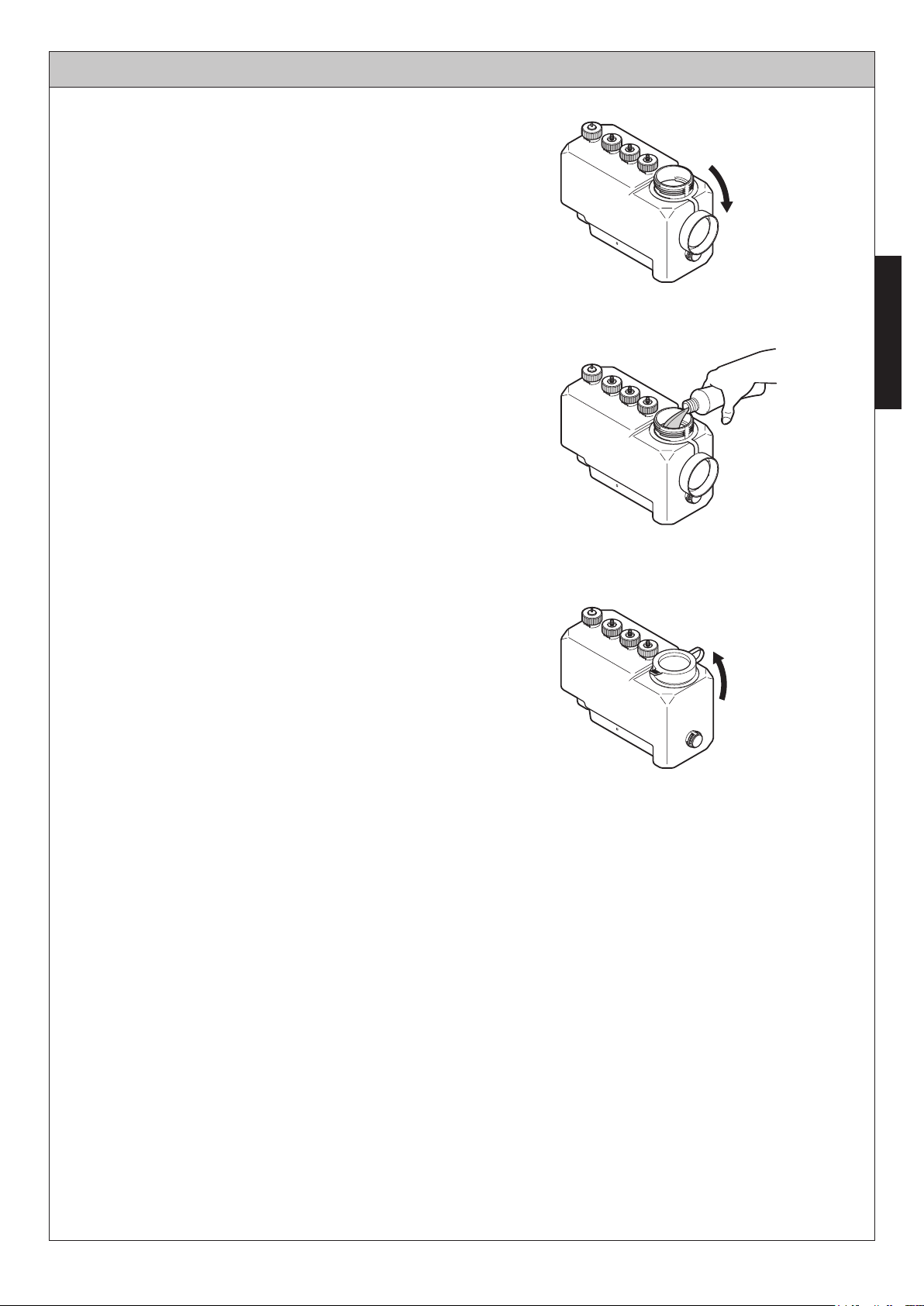
PERIODIC MAINTENANCE - Nozzle
1. Pull out the power plug.
2. Turn the nozzle by hand to unlock.
Unlock
3. Grab the projection on the nozzle with a
tool such as long-nose pliers and pull out
the nozzle and the filter.
4. Clean (Wash with water) the nozzle and the
filter.
Caution
If you wash the nozzle in a wash bowl, block
the drain outlet. This part is small and may be
lost.
Note
After washing them with water, wipe off
moisture with a dry soft cloth.
If you use hot water for cleaning, dirt is
washed off more easily.
Nozzle
Tool
ENGLISH
O-ring
Filter
5. After washing the nozzle and the filter,
mount them back again.
When mounting the nozzle, turn it by hand
so that it locks with the spill hole to the
lower side.
* The nozzle is made so as not to insert
reversely.
Note
After the nozzle has been mounted, turn on
the liquid soap, and make sure that water does
not leak from the outside of the nozzle.
● How to mount the nozzle
View from below
Spill ports
* Be sure to mount the nozzle so that the spill
hole comes to the lower side. Otherwise,
liquid soap may leak.
21
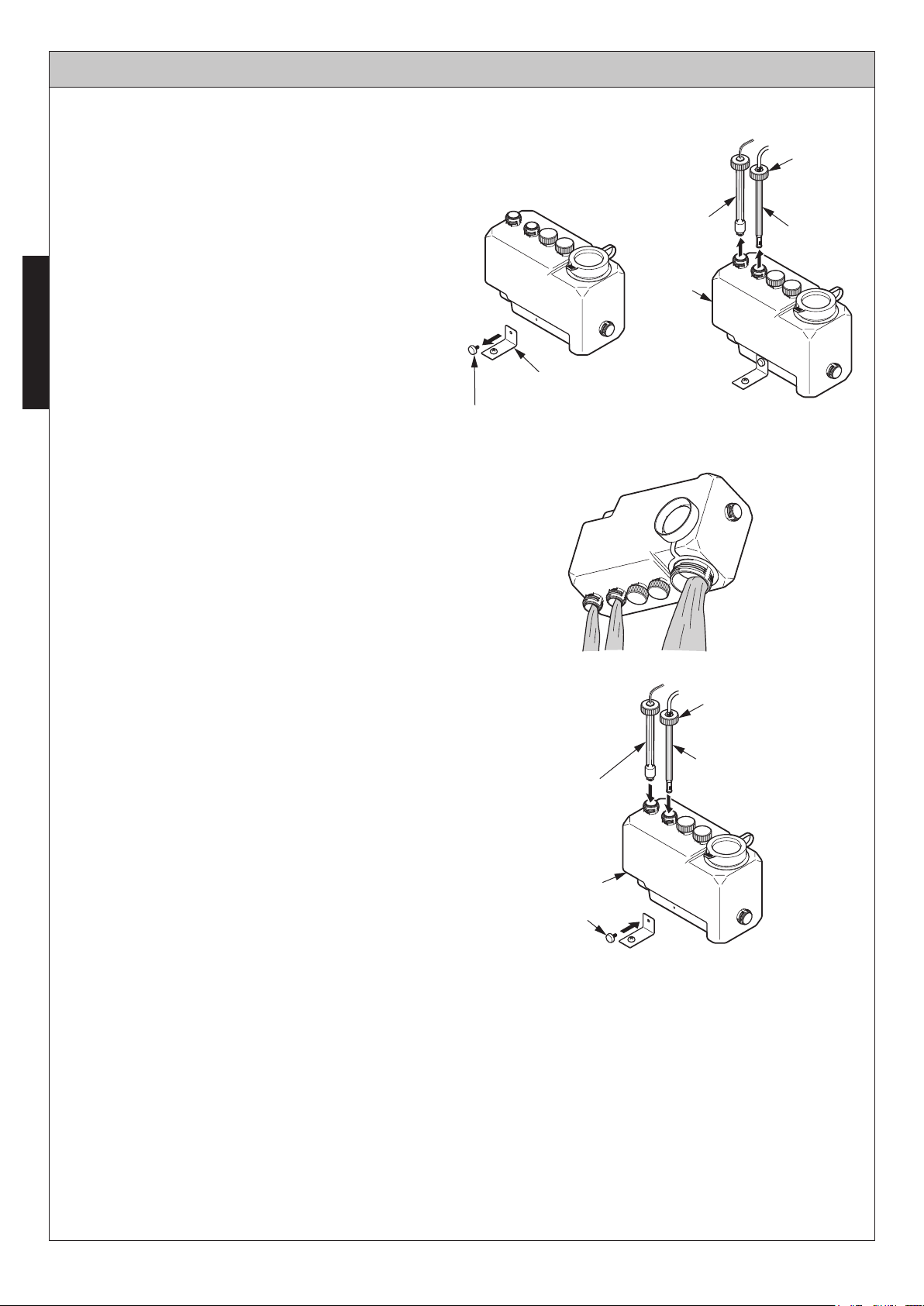
PERIODIC MAINTENANCE - Inside the Tank
In order to use the product comfortably, clean the inside of the tank using
the following procedure.
[ 3L Tank Type ]
Cap nut
1. Remove the cap nut and pull out the float
switch and the tank joint from the tank.
Note
ENGLISH
Store the float switch and the tank joint in a
bucket, etc. to avoid dust adhering to it.
2. Remove the bracket.
If the tank is anchored on the floor or the
wall, turn the decorative screw by hand and
dismount the tank.
3. Wash the tank.
Float switch
Tank joint
Tank
Bracket
Decorative screw
4. Put the tank back in the original position.
5. Put back the float switch and the tank joint.
Note
Mount the packing between the tank joint and
the tank without fail.
6. Mount the tank to the bracket for anchoring.
Cap nut
Tank joint
Float switch
Tank
Decorative
screw
22
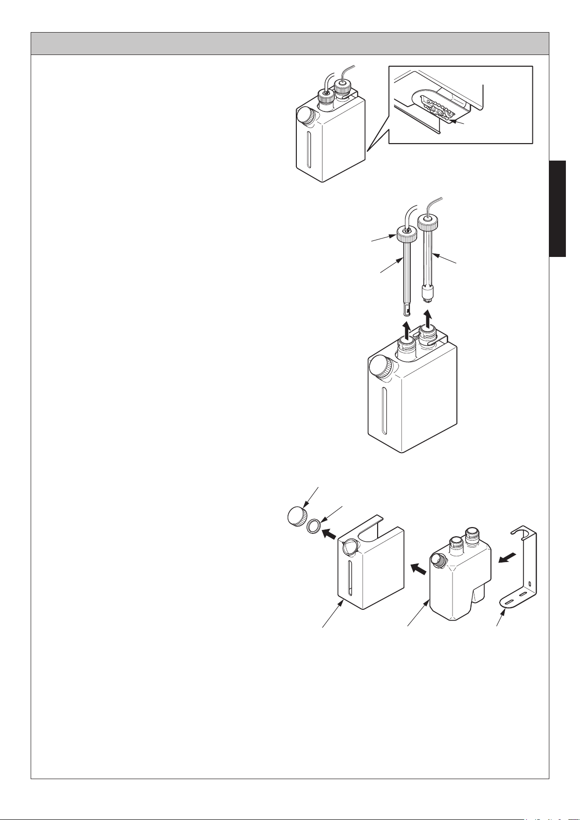
PERIODIC MAINTENANCE - Inside the Tank
[ 1L Tank Type ]
1. Remove the bracket from the underside of
the tank.
2. Remove the cap nut and pull out the float
switch and the tank joint.
(Continued)
Bundling band
Remove it
3. Remove the cap of the supply port and the
ring.
4. Remove the cover and dismount the tank
from the bracket.
Cap nut
Tank joint
Supply port cap
Ring
ENGLISH
Float switch
23
Tank BracketCover
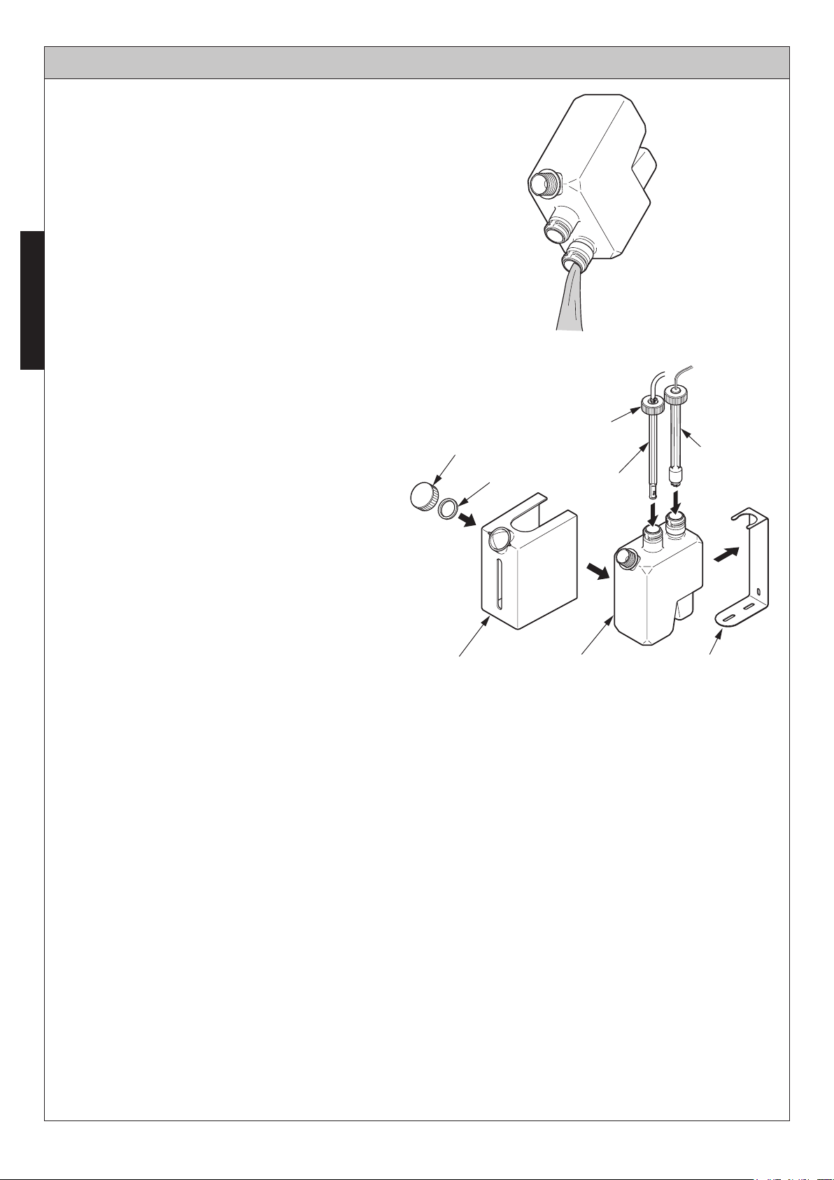
PERIODIC MAINTENANCE - Inside the Tank
5. Wash the tank.
ENGLISH
6. Put the tank back in the original position.
7. Mount the float switch and the tank joint.
8. Mount the cover, the ring and the cap of
supply port.
9. Mount the bracket from the bottom of the
tank.
Supply port cap
Ring
(Continued)
Cap nut
Float switch
Tank joint
Once a month
Check all tube connections for any signs of leakage.
Twice a year
Check all fixed connections and tighten as needed.
Cover Tank Bracket
24
LONG-TERM NON-USE
If there will be long periods of time where the dispenser will not be used, remove all soap from
dispenser using the following method.
1. Remove soap from tank and wash tank out with water.
2. Fill the tank with water and set up the dispenser as usual.
3. Flush the line with water by activating dispenser until no soap comes out from spout.
Refill the tank with water if necessary.
4. Discard any water left in tank and allow tank to dry.
5. Disconnect the power supply until use resumes.
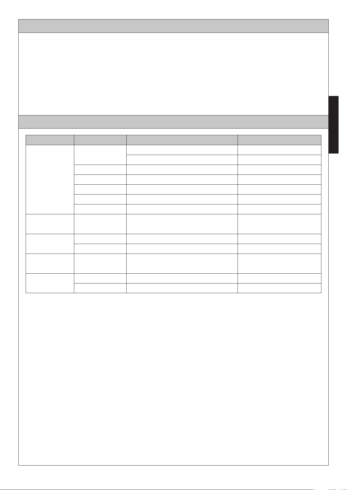
TROUBLESHOOTING
Problem Operating
Red LED flashing
Red LED lighting-up
No soap
comes out
Soap won’t stop
running
It doesn't dispense
mousse
Soap comes out
unexpectedly
Amount of
dispensed soap
is small
Cause Solution
Soap is low
Obstruction in front of sensor window
Pump is not working correctly
-
-
-
-
-
-
-
-
-
-
Sensor window is dirty
Sensor window is disconnected
Power supply is disconnected
Tube is disconnected
Sensor window is dirty Clean sensor window
Air tube (blue) is disconnected
Soap viscosity is high
Soap will be automatic dispersed after 72
hours of non-usage to prevent clogging.
Soap viscosity is high
Filter is clogged
Fill tank with liquid soap
Remove the obstruction
Clean sensor window
Connect cable
Connect cable
Connect tube
Connect air tube
Change to TOTO approved liquid soap
-
Change to TOTO approved liquid soap
Clean filter
ENGLISH
25
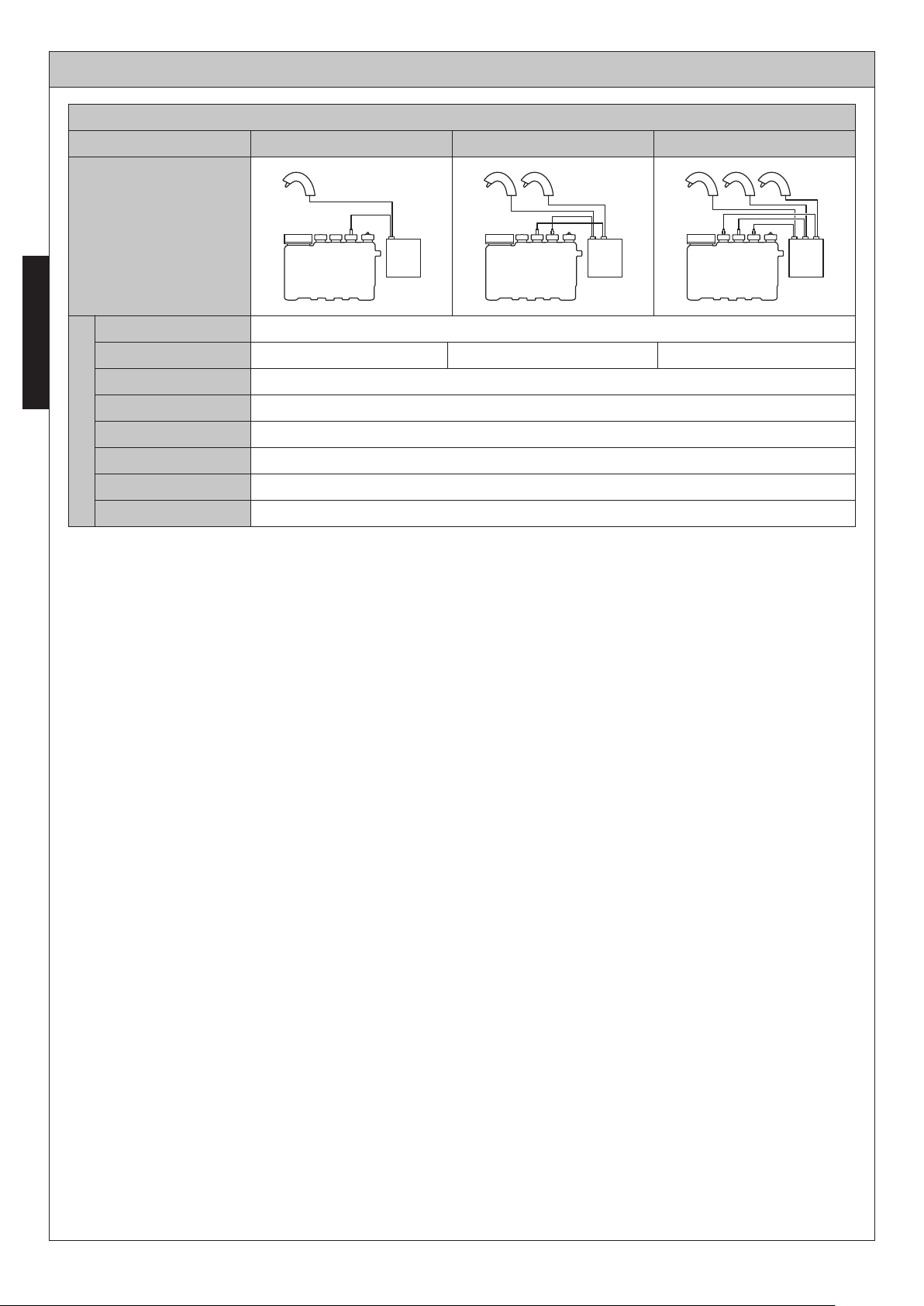
SPECIFICATIONS
<Standard>
ENGLISH
Type
Configuration
Power supply
Wattage
Sensor detection range
Ambient Temperature
Humidity
Power Cord Length
Specifications
Soap volume
Tank Capacity
TLK01101U
5-1/8''~7-7/8'' (130~200 mm) sensor is self-adjusting
TLK01102U TLK01103U
AC 120 V
6.5 W4 W 9 W
34~104°F (1~40°C)
Max.90% RH
55'' (1.4 m)
0.04 o.z (at factory setting)
Approximately 0.8 gallon (3 L) (Usable Capacity)
26
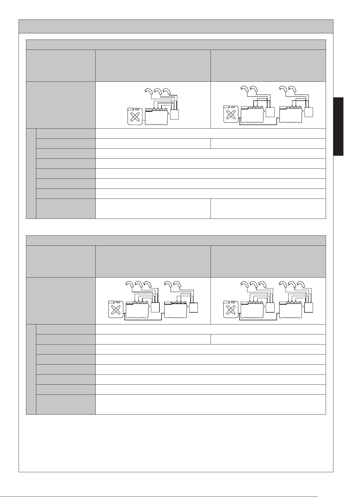
SPECIFICATIONS
<Use with subtank>
(Continued)
Type
Configuration
Power supply
Wattage
Sensor detection range
Ambient Temperature
Humidity
Power Cord Length
Specifications
Soap volume
Tank Capacity
TLK03001G × 3
TLK01107U × 1
TLK01401U × 1
AC 120 V
9 W
5-1/8''~7-7/8'' (130~200 mm) sensor is self-adjusting
34~104°F (1~40°C)
Max.90% RH
55'' (1.4m)
0.04 o.z (at factory setting)
6.1 gallons (23 L)
(usable capacity)
Approximately 6.9 gallons (26 L)
TLK03001G × 4
TLK01106U × 2
TLK01401U × 1
(Usable Capacity)
13 W
ENGLISH
Type
Configuration
Power supply
Wattage
Sensor detection range
Ambient Temperature
Humidity
Power Cord Length
Specifications
Soap volume
Tank Capacity
<Use with subtank>
TLK03001G × 5
TLK01106U × 1
TLK01107U × 1
TLK01401U × 1
AC 120 V
15.5 W 18 W
5-1/8''~7-7/8'' (130~200 mm) sensor is self-adjusting
34~104°F (1~40°C)
Max.90% RH
55'' (1.4m)
0.04 o.z (at factory setting)
Approximately 6.9 gallons (26 L)
(Usable Capacity)
TLK03001G × 6
TLK01107U × 2
TLK01401U × 1
27
THREE YEAR LIMITED WARRANTY
Warranty applies to select Electronic Flush Valves, Faucets and Soap Dispensers only.
1. TOTO warrants its electronic flush valves, faucets and soap dispensers (“Product”) to be free from defects in
materials and workmanship during normal use when properly installed and serviced, for a period of three (3)
years from date of purchase. This limited warranty is extended only to the ORIGINAL PURCHASER of the
Product and is not transferable to any third party, including but not limited to any subsequent purchaser or
owner of the Product. This warranty applies only to TOTO Product purchased and installed in North, Central
and South America.
2. TOTO’s obligations under this warranty are limited to repair, replacement or other appropriate adjustment, at
ENGLISH
TOTO’s option, of the Product or parts found to be defective in normal use, provided that such Product was
properly installed, used and serviced in accordance with instructions. TOTO reserves the right to make such
inspections as may be necessary in order to determine the cause of the defect. TOTO will not charge for labor
or parts in connection with warranty repairs or replacements. TOTO is not responsible for the cost of removal,
return and/or reinstallation of the Product.
3. This warranty does not apply to the following items:
a. Damage or loss sustained in a natural calamity such as fire, earthquake, flood, thunder, electrical storm, etc.
b. Damage or loss resulting from any accident, unreasonable use, misuse, abuse, negligence, or improper
care, cleaning, or maintenance of the Product.
c. Damage or loss resulting from sediments or foreign matter contained in a water system.
d. Damage or loss resulting from improper installation or from installation of the Product in a harsh and/or
hazardous environment, or improper removal, repair or modification of the Product.
e. Damage or loss resulting from electrical surges or lightning strikes or other acts which are not the fault of
TOTO or which the Product is not specified to tolerate.
f. Damage or loss resulting from normal and customary wear and tear, such as gloss reduction, scratching or
fading over time due to use, cleaning practices or water or atmospheric conditions, including but not limited
to, the use of bleach, alkali, acid cleaners, dry (powder) cleaners or any other abrasive cleaners or the use
of metal or nylon scrubbers.
4. In order for this limited warranty to be valid, proof of purchase is required. TOTO encourages warranty
registration upon purchase to create a record of Product ownership at http://www.totousa.com. Product
registration is completely voluntary and failure to register will not diminish your limited warranty rights.
5. THIS WARRANTY GIVES YOU SPECIFIC LEGAL RIGHTS. YOU MAY HAVE OTHER RIGHTS WHICH
VARY FROM STATE TO STATE, PROVINCE TO PROVINCE OR COUNTRY TO COUNTRY.
6. To obtain warranty repair service under this warranty, you must take the Product or deliver it prepaid to a TOTO
service facility together with proof of purchase (original sales receipt) and a letter stating the problem, or
contact a TOTO distributor or products service contractor, or write directly to TOTO U.S.A., INC., 1155
Southern Road, Morrow, GA 30260 (888) 295 8134 or (678) 466-1300, if outside the U.S.A. If, because of the
size of the Product or nature of the defect, the Product cannot be returned to TOTO, receipt by TOTO of written
notice of the defect together with proof of purchase (original sales receipt) shall constitute delivery. In such
case, TOTO may choose to repair the Product at the purchaser’s location or pay to transport the Product to a
service facility.
THIS WRITTEN WARRANTY IS THE ONLY WARRANTY MADE BY TOTO. REPAIR, REPLACEMENT OR
OTHER APPROPRIATE ADJUSTMENT AS PROVIDED UNDER THIS WARRANTY SHALL BE THE
EXCLUSIVE REMEDY AVAILABLE TO THE ORIGINAL PURCHASER. TOTO SHALL NOT BE
RESPONSIBLE FOR LOSS OF THE PRODUCT OR FOR OTHER INCIDENTAL, SPECIAL OR
CONSEQUENTIAL DAMAGES OR EXPENSES INCURRED BY THE ORIGINAL PURCHASER, OR FOR
LABOR OR OTHER COSTS DUE TO INSTALLATION OR REMOVAL, OR COSTS OF REPAIRS BY OTHERS,
OR FOR ANY OTHER EXPENSE NOT SPECIFICALLY STATED ABOVE. IN NO EVENT WILL TOTO’S
RESPONSIBILITY EXCEED THE PURCHASE PRICE OF THE PRODUCT. EXCEPT TO THE EXTENT
PROHIBITED BY APPLICABLE LAW, ANY IMPLIED WARRANTIES, INCLUDING THAT OF
MERCHANTABILITY OR FITNESS FOR USE OR FOR A PARTICULAR PURPOSE, ARE EXPRESSLY
DISCLAIMED. SOME STATES DO NOT ALLOW LIMITATIONS ON HOW LONG AN IMPLIED WARRANTY
LASTS, OR THE EXCLUSION OR LIMITATION OF INCIDENTAL OR CONSEQUENTIAL DAMAGES, SO THE
ABOVE LIMITATION AND EXCLUSION MAY NOT APPLY TO YOU.
28
ÍNDICE
¡GRACIAS POR ELEGIR TOTO! ....................................................................................................29
ADVERTENCIAS ............................................................................................................................29
ANTES DE LA INSTALACIÓN ........................................................................................................29
PIEZAS INCLUIDAS .......................................................................................................................30
PROCEDIMIENTO DE INSTALACIÓN ...........................................................................................32
PRUEBAS .......................................................................................................................................43
MODO DE USO...............................................................................................................................44
RECARGA DEL TANQUE............................................................................................................... 45
AJUSTE DE MODO.........................................................................................................................46
CUIDADO Y LIMPIEZA ...................................................................................................................47
MANTENIMIENTO PERIÓDICO .....................................................................................................48
FALTA DE USO DURANTE PERÍODOS PROLONGADOS........................................................... 52
SOLUCIÓN DE PROBLEMAS ........................................................................................................52
ESPECIFICACIONES .....................................................................................................................53
GARANTÍA LIMITADA DE TRES AÑOS......................................................................................... 55
DIMENSIONES DE LA ESTRUCTURA INTERIOR ......................................................................110
¡GRACIAS POR ELEGIR TOTO!
La misión de TOTO es ofrecer al mundo estilos de vida saludables, higiénicos y más cómodos.
Diseñamos cada producto con un equilibrio entre forma y función como un principio orientador.
Felicitaciones por su elección.
ADVERTENCIAS
Lea y siga las siguientes notas. No hacerlo podría producir lesiones personales o daños a la
propiedad.
Ninguna otra persona que no sea el ingeniero de servicio puede desmontar, reparar ni
modificar este dispensador, a menos que se describa específicamente en este manual.
No hacerlo podría producir un choque eléctrico o el mal funcionamiento del equipo.
No utilice el dispensador en una ubicación húmeda en donde la condensación pueda
acumularse en la superficie, especialmente en un sauna o un baño de vapor.
No golpee ni patee el dispensador ni la caja del controlador ya que puede dañar la unidad o producir una fuga.
No utilice el dispensador si la temperatura ambiente desciende a bajo cero.
Asegúrese de que el cable de alimentación no entre en contacto con la línea de suministro de agua caliente.
Evite colocar objetos dentro del rango de detección del sensor infrarrojo.
Utilice solo el jabón líquido aprobado por TOTO para evitar la nulidad de la garantía.
Asegúrese de que la toma eléctrica esté en una posición donde no se humedezca durante el uso.
ESPAÑOL
ANTES DE LA INSTALACIÓN
Lea estas instrucciones detenidamente para garantizar la instalación adecuada.
TOTO se reserva el derecho de actualizar el diseño del producto sin aviso.
Realice una verificación para asegurarse de que cuenta con las piezas indicadas en la
siguiente página.
29
(TLK03001G)
PIEZAS INCLUIDAS
Tanque de 3 l
ControladorConjunto de la boquilla
(Φ 5,1 x 32)
Tornillo
Soporte
Placa de anclaje
Tornillo roscador
avellanado
(Φ 4 x 10)
ESPAÑOL
Tapa del acceso
de suministro
Conjunto de soportes
(solo para tanque de 3 l)
Tornillo
(Φ 5,1 x 32)
Soporte
Tornillo
decorativo
Manguera 2 m (6,6')
(tipo simple: 1; tipo doble: 2;
tipo triple: 3)
Abrazadera para manguera
(tipo simple: 2; tipo doble: 4;
tipo triple: 6)
* Tanque de 1 l (pedido especial)
Tapa del acceso
de suministro
Manguera de 18 cm (7,1")
Abrazadera para
manguera: 2
Soporte
Banda de
agrupación
Tornillo de cabeza redonda
(Φ 5,1 x 32)
30
 Loading...