

Page 1
!
MiniLab User Guide
!
Totem by UAB Aldrea
ver 1.1!
Page 2

www.totemmaker.net
Totem MiniLab
Table of contents
Introduction 3 .........................................................
Who is it for 3 ......................................................................................................................
What’s in the box 3 ..............................................................................................................
Overview 4 ..............................................................
LabBoard 4 ...........................................................................................................................
TotemDuino 5 ......................................................................................................................
Using MiniLab 6 .....................................................
Powering up 6 ......................................................................................................................
Measuring voltages 8 ...........................................................................................................
Setting output voltage 9 .......................................................................................................
Digital inputs 11 ...................................................................................................................
Frequency meter 13 .............................................................................................................
Measuring current 14 ..........................................................................................................
Setting programmable voltage output 16 ............................................................................
Using pulse counter 18 ........................................................................................................
Generating pulses 19 ............................................................................................................
Programming with MiniLab 22 ..............................
Connecting MiniLab to your computer 22 ..........................................................................
Using Arduino IDE 23 .........................................................................................................
Expanding MiniLab 28 ...........................................
Using breadboards 28 .........................................................................................................
Side panels 29 ......................................................................................................................
What’s next 31.........................................................
! of !2 31
Page 3

www.totemmaker.net
Totem MiniLab
Introduction
We at Totem congratulate you on getting your first electronics laboratory! Totem MiniLab
contains all the necessities for starting your path in the world of electronics and
programming. This document will guide you through all the steps in getting to know your
MiniLab, setting it up and learning about all of its capabilities.
Using MiniLab should be simple and fun! While building it, we tried to address and
improve all the negative parts about prototyping — no longer you’ll have to deal with
messy wiring, fragile connections and headaches of where to mount every separate part of
your experiment.
MiniLab is meant to be used together with Totem construction system which allows users
to build solid workbenches with integrated breadboards, as well as available expansion
boards which can expand the capabilities of the MiniLab even further.
Who is it for
Our main goal with MiniLab is to make a platform which would give an easy and
approachable way for students and young makers communities to build up on, using it as
a stepping stone into the world of electronics and programming.
While not intended to be used in place of a professional level equipment, MiniLab has its
own advantages — small size, speed of setup and versatility could find its place in any
makers shop.
What’s in the box
In the MiniLab kit you’ll find:
• TotemDuino - our improved version of Arduino UNO platform,
• LabBoard - a capable experimentation and measuring platform,
• 34-pin flat cable — use it to connect TotemDuino and LabBoard together,
• Collection of Totem construction parts — for building Totem workbench.
• Voltage adapter — to power MiniLab from the mains,
• Breadboards — to extend your experimentation area,
• Breadboard cables — short male to male cables useful for experimentation,
• Building instructions — suggested use of Totem parts for building a workbench
where everything neatly mounts together.
! of !3 31
Page 4
www.totemmaker.net
Totem MiniLab
Overview
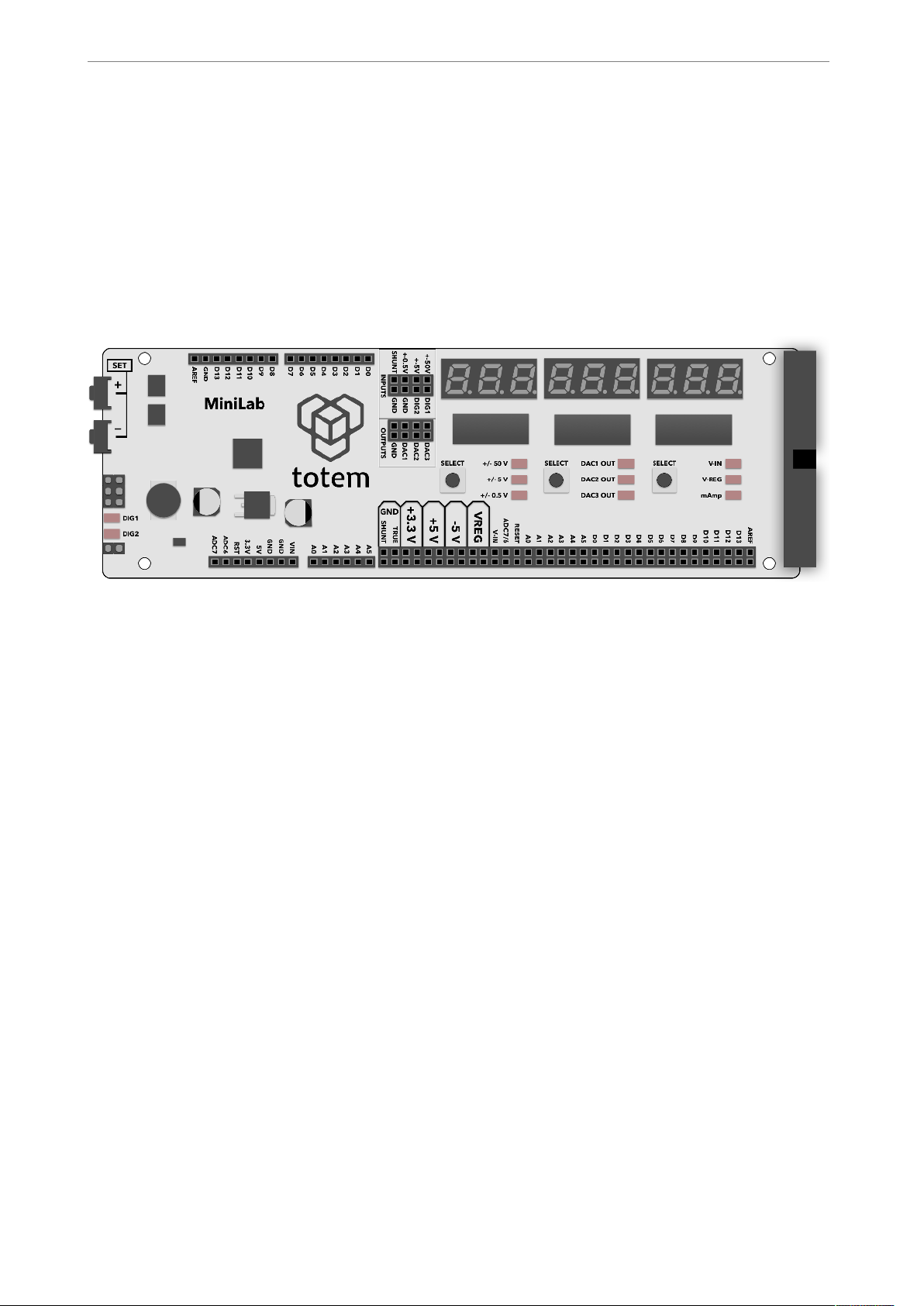
MiniLab at its core consists of two main parts - LabBoard and TotemDuino. In this
chapter, their main attributes are presented together with a quick feature list. While the
best functionality is achieved when using them together connected via supplied flat cable,
they can fully function on their own, keeping in mind that some functionality such as
TotemDuino connections will not be available without main TotemDuino board.
LabBoard
!
Fig. 1 MiniLab board overview
This board has a dual use — firstly it can be used as an expansion board to the
TotemDuino system, offering easily accessible input and output connections, and secondly
— it is a measuring and testing unit, containing such modules as:
• Digital to Analog converter — a 3 channel, 12 bit converter, capable of outputting a
pre-set voltage in the 0-2.5V range.
• Voltage measure — three inputs in the +-0.5 V, +-5V and +-50V range.
• Current measure — sensing current up to 800 mA.
• Frequency meter — digital signal frequency measurement module, capable of signals
up to 1 MHz.
• Pulse counter — digital signal pulse counter, counting up to 999999999 pulses in a
signal.
• Pulse generator — unit capable of generating finite or infinite series of pulses, with
programmable pulse width and period.
! of !4 31
Page 5
www.totemmaker.net
Totem MiniLab
TotemDuino
!
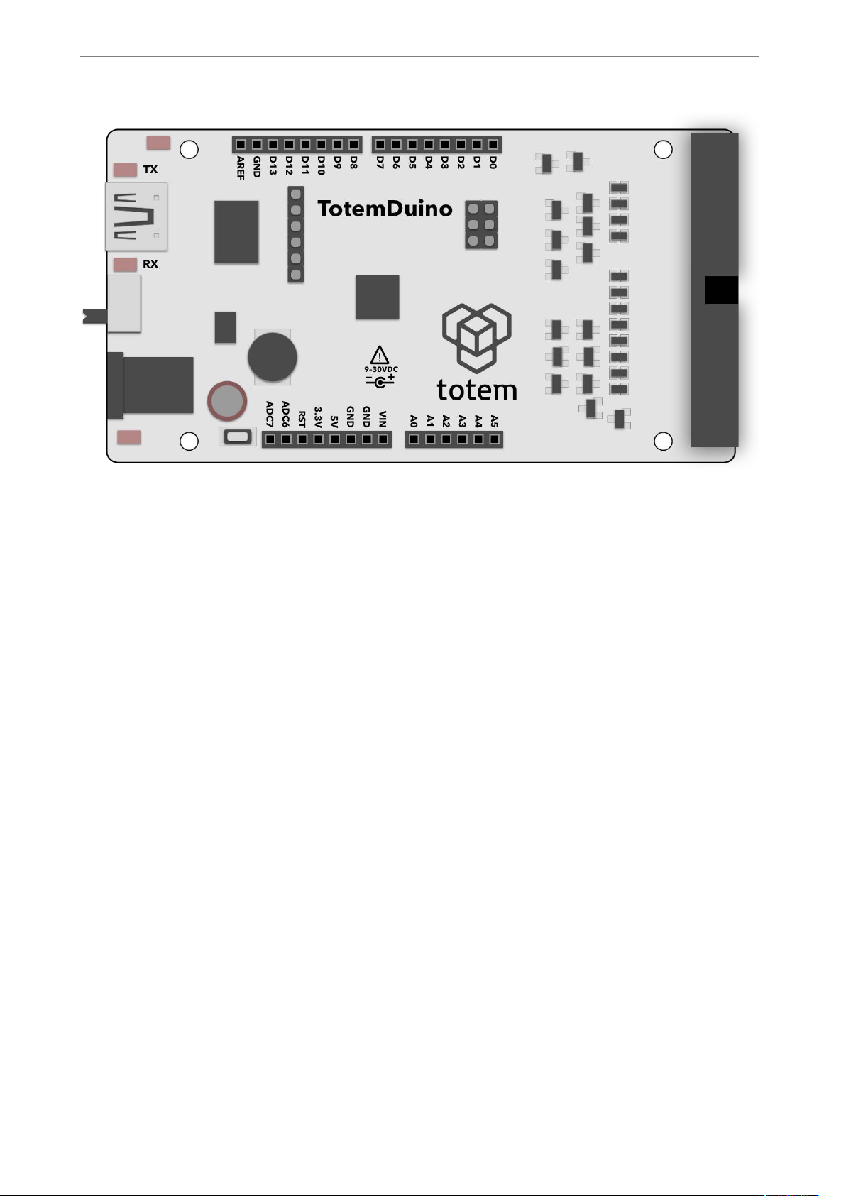
Fig. 2 TotemDuino board
TotemDuino expands upon the great Arduino UNO platform idea. While it is kept fully
backwards compatible with Arduino, a lot of additional features are included as well, such
as:
• Output protection — nothing limits creativity as the fear of making a mistake and
breaking something. TotemDuino comes with all of its output pins going into LabBoard
protected against over-voltage or short-circuit conditions. No experiment could go
wrong this way!
• Expansion port — a 34 pin flat-cable connection connects to the LabBoard for easy
pin access.
• Powerful 5 V regulator — you'll be less likely to run out of power while
experimenting with higher power loads such as motors.
• Selectable microcontroller logic voltage — as the world progresses from 5 V
towards 3.3 V logic voltage, TotemDuino can work with both just by the flip of a switch,
without the need for any additional adapters or converters.
! of !5 31
Page 6
www.totemmaker.net
Totem MiniLab
Using MiniLab
In this chapter all of the main features of the MiniLab are explained and a usage example
is provided for each of intended use-case. Features discussed here do not affect
TotemDuino, and work independently from it, so no matter what code or experiment
you’re working on at a given time, all of the LabBoard features are still available to use.
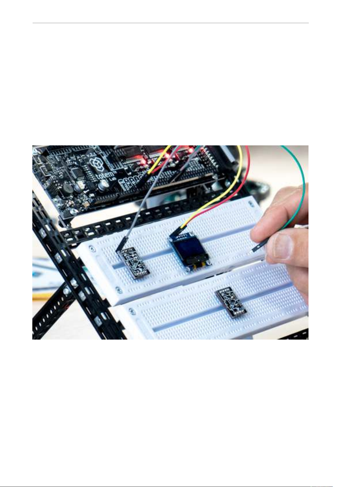
If used together with suggested Totem construction system, MiniLab is mounted in the
workbench style system, which allows easy access to all of available pins, as well as
breadboard work area.
Fig. 3 An ongoing experiment on MiniLab workbench
Powering up
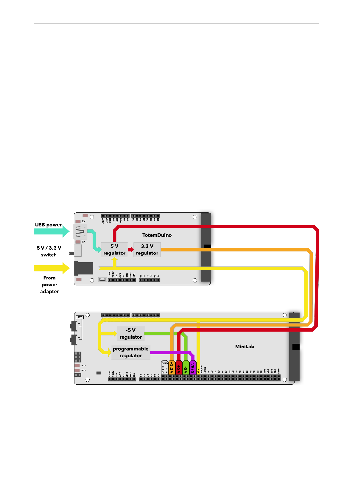
MiniLab comes with a 12 V, 1.5 Amp external power supply. Internally, supply voltage is
then regulated into several voltages needed to run various parts of the system. Each of
these can be used during measurements or experiments, as they do have easily accessible
pins that equipment can be connected to.
While MiniLab can easily use any of the available voltage for your experiments, digital
signals going to and from TotemDuino shouldn’t be higher than the currently selected
! of !6 31
Page 7
www.totemmaker.net
Totem MiniLab
running voltage for it. A selector switch on the TotemDuino board can set the supply
voltage for the TotemDuino microcontroller either at 5 or 3.3 volts. This allows you to set
the logic level interfacing with various external equipment that could only be used at one
of these voltages without any additional voltage level converters. Refer to TotemDuino
section for explanation on how to set the voltage.
Voltages that are available to use are:
• 12 V, 1.0 A — direct supply voltage,
• 5 V, 0.5 A — regulated supply voltage, shared with TotemDuino,
• 3.3 V, 0.25 A — regulated supply voltage, shared with TotemDuino and LabBoard
processor,
• -5 V, 0.5 A — separate regulated voltage, for experimentation with operation amplifiers,
• 0..3.3 V programmable regulated voltage output, up to 0.35 A.
A power supply schematic is provided for reference:
!
Fig. 4 Power regulators in MiniLab
It is possible to run only from USB power, but in that case modules relying on higher
voltage, such as programmable regulator will not be available.
! of !7 31
Page 8
www.totemmaker.net
Totem MiniLab
Measuring voltages
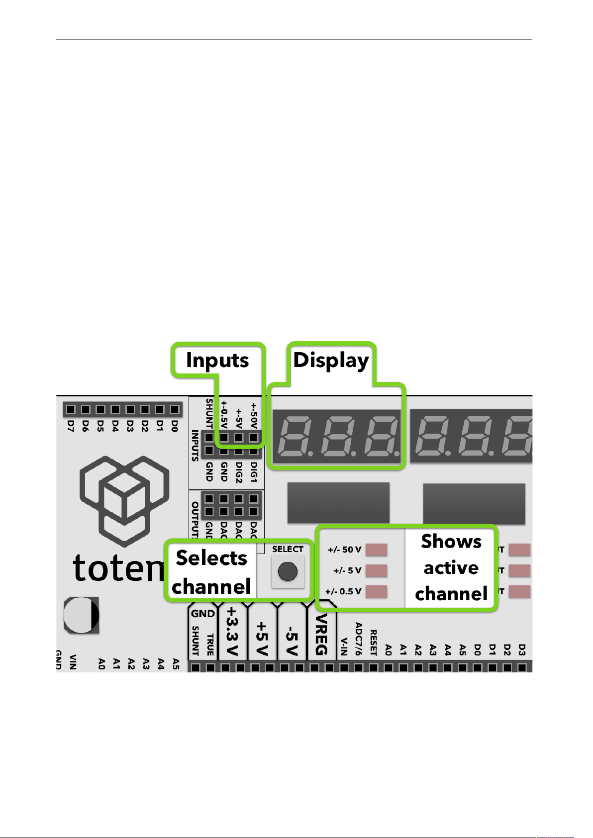
LabBoard has a 3 channel voltage measurement module. Each has a pre-set measurement
range:
• ± 0.5 V - best to be used when measuring small scale signals when maximum precision
is required.
• ± 5 V - for measuring TTL logic level signals.
• ± 50 V - for external signal measuring.
Left display is used in the LabBoard for showing currently measured voltage. Currently
active channel is selected with a button under the display, and the current active channel
LED lights up.
Display shows value in millivolts when using ± 0.5 V channel, otherwise the output is in
Volts. Blinking display indicates that currently measured voltage is negative.
!
Fig. 5 Voltage measuring module
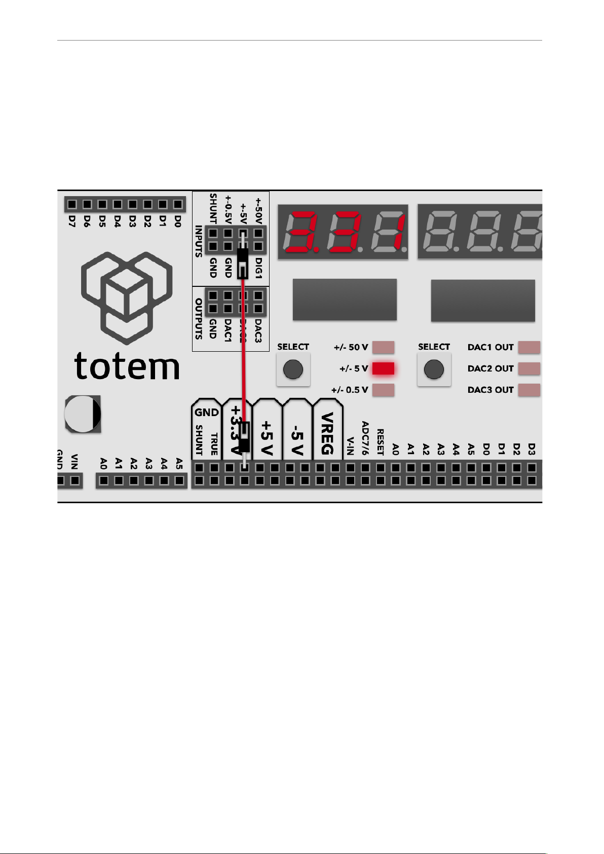
Example
1. Connect the ± 5 V input with a 3.3 Volt output.
! of !8 31
Page 9
www.totemmaker.net
Totem MiniLab
2. Press the channel selector button until the ± 5 V input LED lights up.
3. Observe the display — it should indicate a value close to 3.3 Volts:
!
Fig. 6 Measuring one of the supply voltages
Setting output voltage
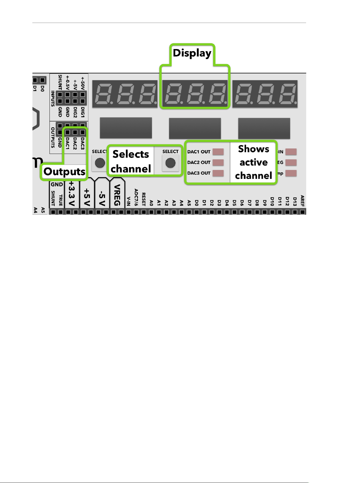
Using inbuilt 3 channel Digital to Analog Converter (DAC) allows you to output any
voltage in the 0..3V range, at up to 15 mA current. This is useful for experimenting with
comparators or operational amplifiers, as they need various reference or input voltages.
! of !9 31
Page 10
www.totemmaker.net
Totem MiniLab
!
Fig. 7 Programmable output voltage
Middle display is used for showing the current output voltage for the active channel,
which itself is indicated by the middle column of LED’s. Pressing middle SELECT button
allows you to change the active channels. To edit currently preset voltage, SELECT button
must be held until LED starts blinking. Then SET+ and SET- buttons can be pressed to
adjust currently selected channels voltage. All other inactive channels still keep the same
preset voltage until it’s changed by SET buttons on the side of the board.
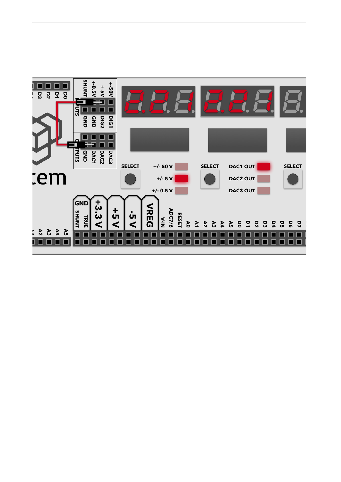
Example
1. Connect the DAC1 output to the ± 5 V voltage measuring channel input.
2. Using middle select button switch the current output channel until DAC1 Out LED
lights up.
3. Using left select button switch the measure channel to ± 5 volts.
4. Hold SELECT button until DAC1 Out LED starts to blink.
5. Using Set+ and Set- button change the output value of the DAC1 channel.
6. Observe that voltage measure display follows the same value as the DAC output one.
! of !10 31
Page 11
www.totemmaker.net
Totem MiniLab
!
Fig. 8 Example usage of output voltage module
Digital inputs
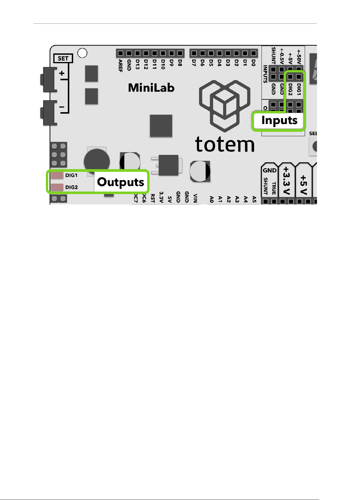
MiniLab has a two channel digital input module, meant to indicate the current logic state
of the signal with an LED.
! of !11 31
Page 12
www.totemmaker.net
Totem MiniLab
!
Fig. 9 Using digital inputs
0 to 6 Volts are accepted input range. A low input value (0..1.3V) turns of corresponding
LED, where a high value (1.8V..6V) turns the LED on.
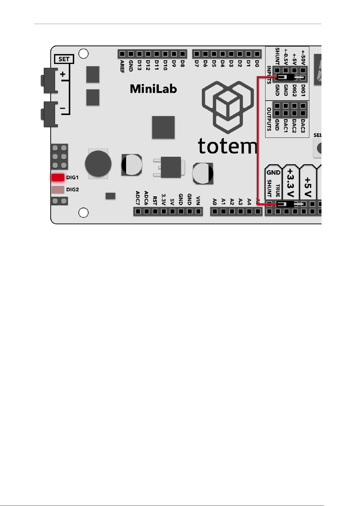
Example
1. Connect DIG1 input with +5V output
2. Observe that DIG1 LED follows the state of the input by lighting up.
! of !12 31
Page 13
www.totemmaker.net
Totem MiniLab
!
Fig. 10 Example usage of Digital input
Frequency meter
This module allows to measure digital signal frequency in 0..1 MHz range. This is a
special mode, which temporarily disables all other modules while this one is active.
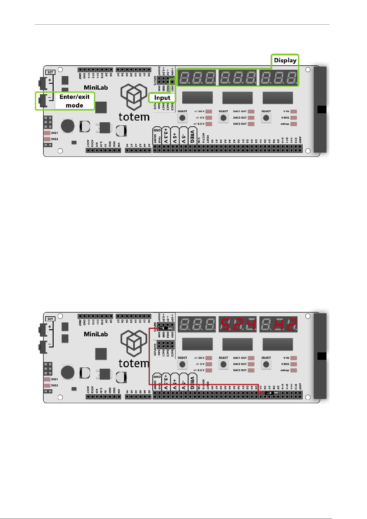
To enter into frequency measurement mode, hold the SET- button until the display clears
up and shows “H2”.
Frequency meter uses DIG1 as its input. Only signals in the amplitude from 3.3 V to 5 V
can be measured.
! of !13 31
Page 14
www.totemmaker.net
Totem MiniLab
!
Fig. 11 Frequency measurement module
Experiment
1. First find a source digital signal with the frequency that you want to measure. As an
example, you could use a “PlayMelody” sketch from Arduino webpage, which plays a
tone on one of digital outputs.
2. Code the sketch to TotemDuino.
3. Connect the digital signal (in the “PlayMelody” example, D9 is used) with the
frequency meter input DIG1 pin.
4. Observe that frequency meter measured a frequency (in the “PlayMelody” case it
should be close to 524 Hz).
!
Fig. 12 Measuring 524 Hz signal with LabBoard
Measuring current
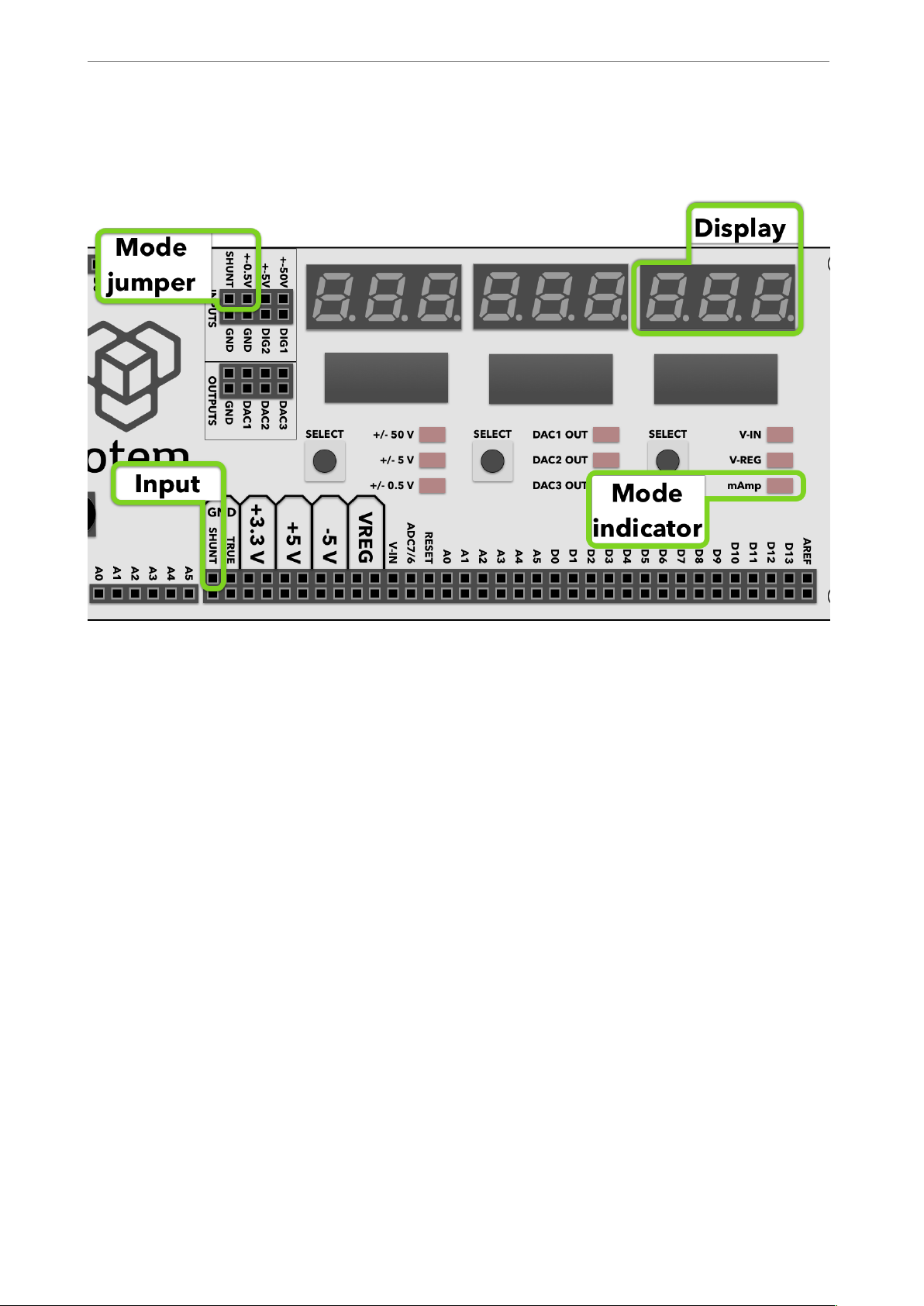
TotemDuino has a current measuring module, which allows to measure current up to 800
mAmps. Rightmost display is used for showing current measurement result, when the
! of !14 31
Page 15
www.totemmaker.net
Totem MiniLab
current mode is mAmp (indicated by an LED). As the current sensor reuses the same
hardware as used in voltage measurement module, you need to connect the signal from
the shunt resistor with +-0.5 V channel:
!
Fig. 13 Current measuring module
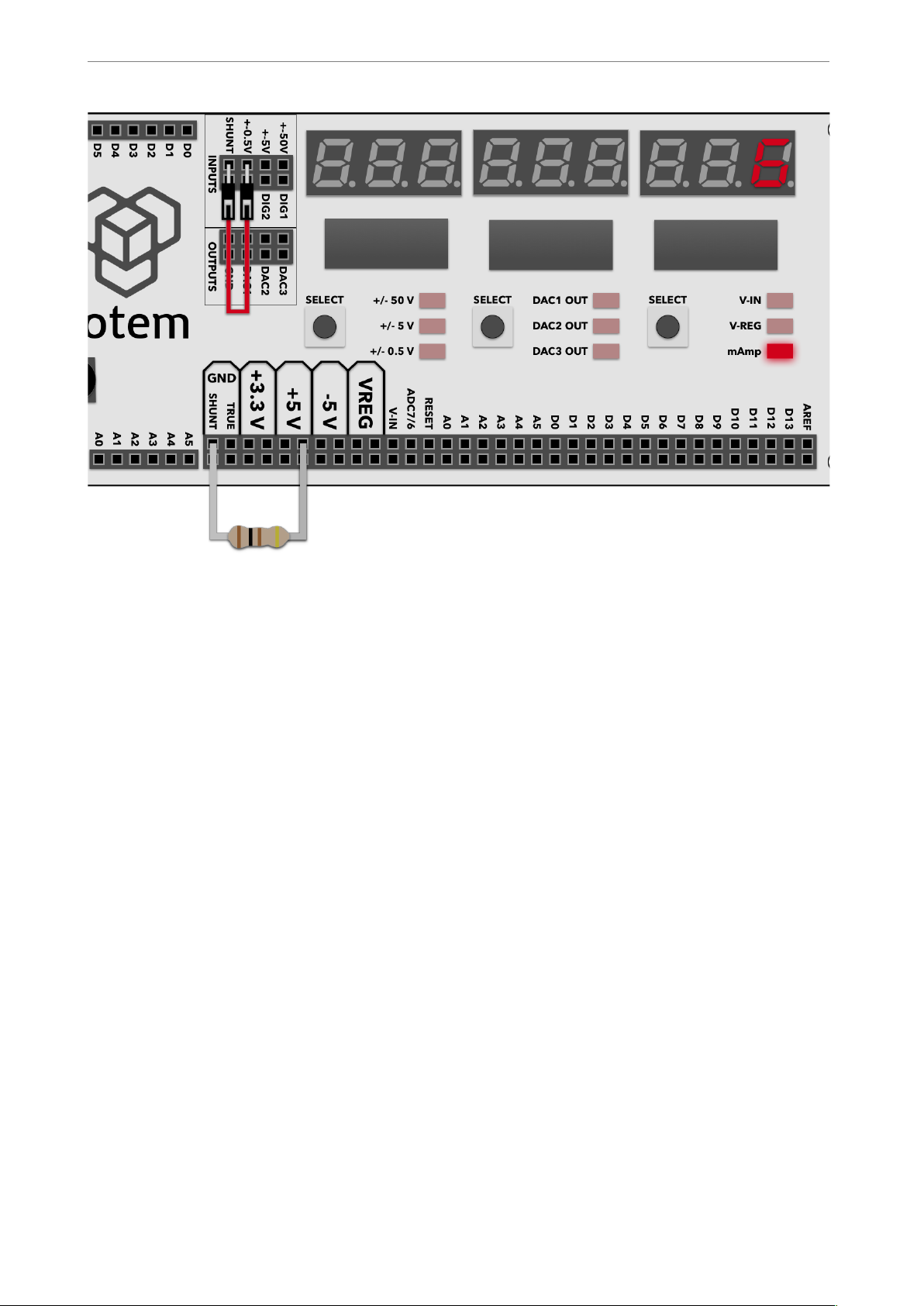
Experiment
1. Connect SHUNT and ± 0.5 V input together.
2. Connect any external circuit (in this example a 100 Ohm resistor is used), powering it
from the LabBoard +5 V output, but instead of connecting negative end to ground,
connect it to SHUNT ground pin.
3. Using right select button switch into mAmp mode.
4. Observe that it measures close to 5 mA.
! of !15 31
Page 16
www.totemmaker.net
Totem MiniLab
!
Fig. 14 Current measuring example using 100 Ohm resistor
Setting programmable voltage output
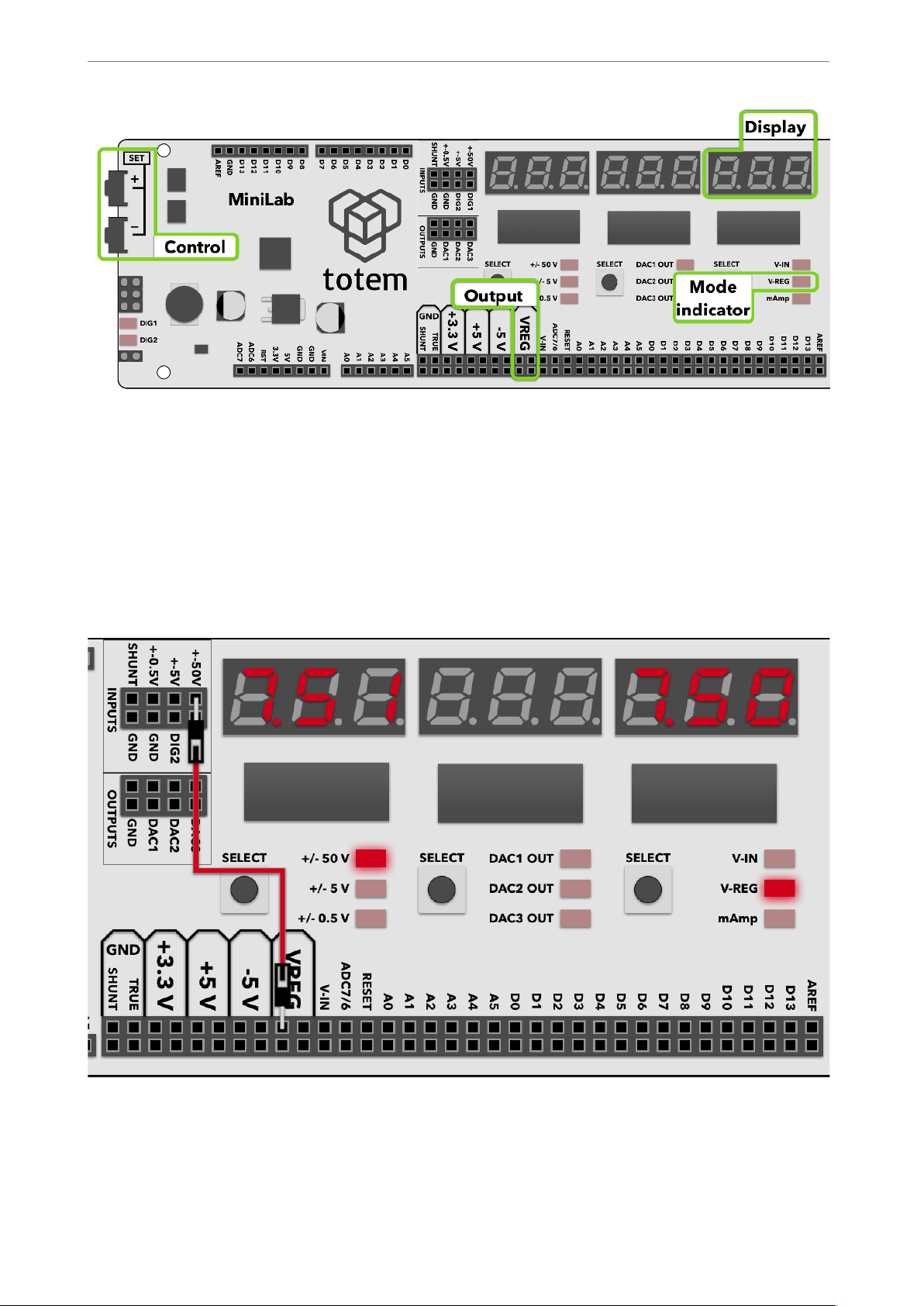
LabBoard has a built-in variable voltage output module, capable of providing up to Vin - 3
V at up to 500 mA. Vin is the supply voltage for the MiniLab (Vin = 12 V when using an
included power adaptor).
Output for the regulator is marked with VREG symbol. The current output value in Volts
is shown on the right display and can be changed with SET+ and SET- buttons when
VREG mode is activated. The last set value persists even when the mode is changed, so
once setup is done, it can be changed to measure current flowing from the VREG.
! of !16 31
Page 17
www.totemmaker.net
Totem MiniLab
!
Fig. 15 Programmable regulated voltage output
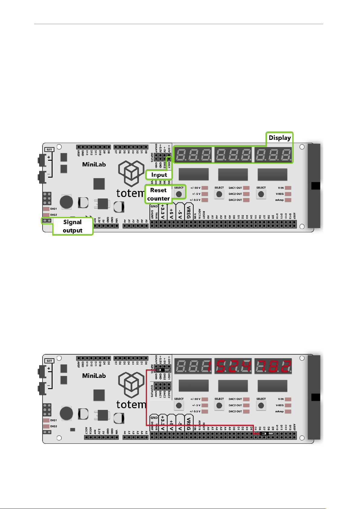
Example
1. Connect VREG together with ± 50 V input.
2. Set the VREG voltage to some value.
3. Observe that the ± 50 V input measurement follows the VREG setting.
!
Fig. 16 Measuring programmable output voltage
! of !17 31
Page 18
www.totemmaker.net
Totem MiniLab
Using pulse counter
LabBoard has a special mode where digital pulses sent to DIG1 are counted. This works
only with digital logic-level signals, and has a maximum frequency of 1 MHz.
Pulse counter mode is selected by holding STEP+ button for at least 3 seconds. When in
this mode, all other features are deactivated. All three displays show the number of pulses
counted, and up to 999999999 pulses can be registered.
To exit back from the pulse counter mode press STEP+ button.
!
Fig. 17 Pulse counter module
Example
1. Similarly to frequency measurement mode, here a digital signal is again needed. In this
example a “blink” demo sketch is used, outputting 1 Hz signal.
2. Connect D9 output pin to DIG1 pulse counter input.
3. Enter pulse counter mode by holding SET+ button.
4. Observe that the counter increments every second.
!
Fig. 18 Pulse counter experiment
! of !18 31
Page 19
www.totemmaker.net
Totem MiniLab
Generating pulses
LabBoard can also be used as a digital signal generator with programmable output signal
period and pulse width. It can work in infinite mode, where signals are generated until
stopped, or in finite mode, when only a preset number of pulses are emitted.
To enter generator mode, hold left SELECT button for at least 3 seconds. This will cause
LabBoard to go into special signal generation mode. In this mode all other modules are
paused, only the generator part is active.
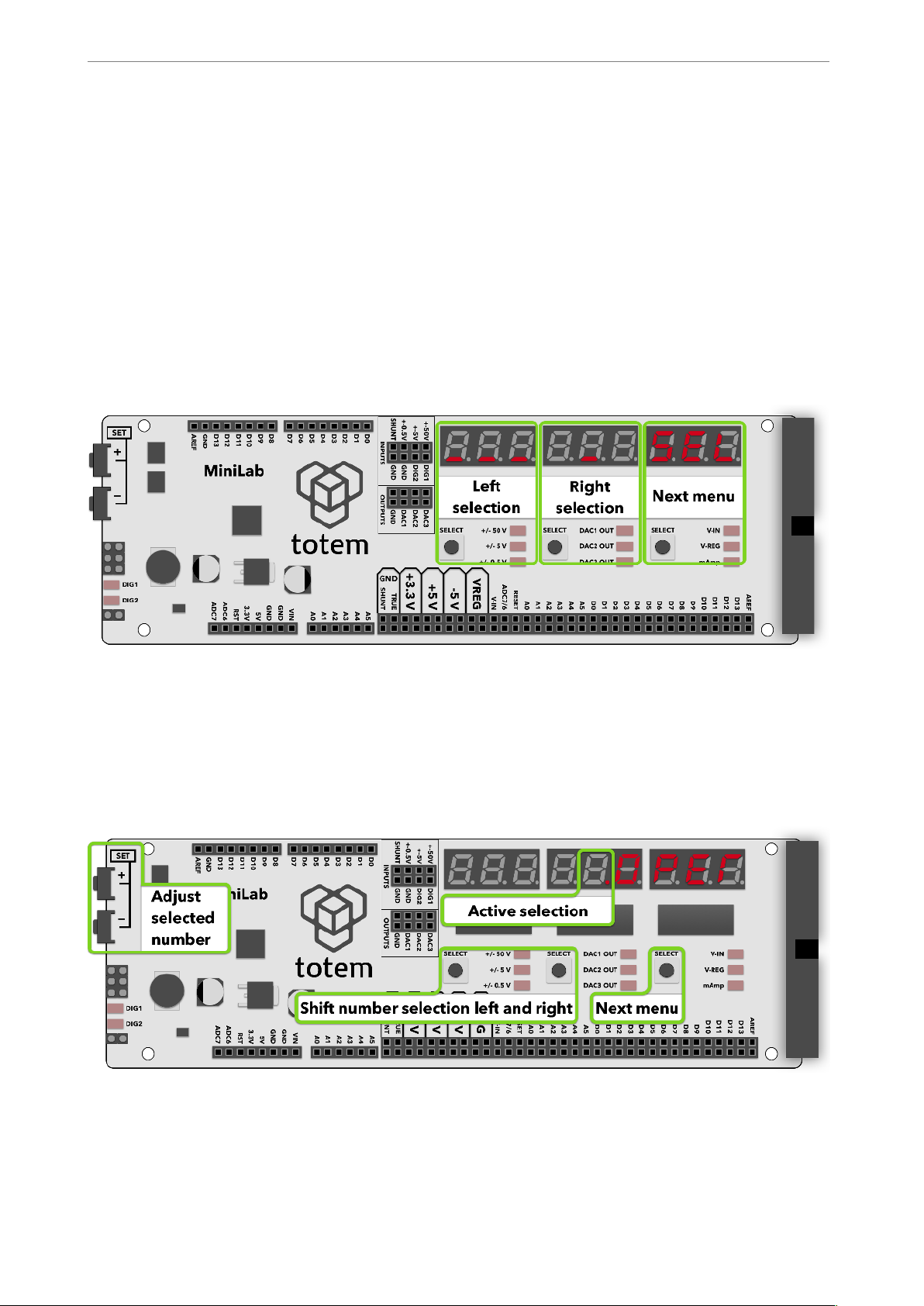
Once in the generator mode, all three screens turns off briefly, then “PPP” is presented on
the leftmost screen. Pressing corresponding SELECT button enters into signal generation
mode configuration screen. This is confirmation entry mode:
!
Fig. 19 Confirmation mode entry
While entering numerical value in numerical entry mode in the configuration menu,
rightmost SELECT button always toggles over available configuration entry, middle and
left SELECT are used for selecting currently active number (indicated by a blinking dot)
to be adjusted with SET+ and SET- buttons. This is a numerical entry mode:
!
Fig. 20 Numerical mode entry
In the following list, all available menu entries are described. Refer to figures above
describing how to orientate in the menu system.
! of !19 31
Page 20
www.totemmaker.net
Totem MiniLab
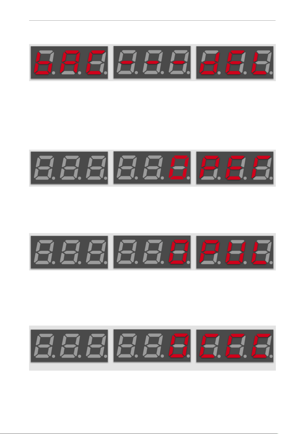
1. Delete settings / Exit mode screen, confirmation mode type:
!
Fig. 21 Delete/Exit mode screen
Left selection — exit from pulse generation mode,
Right selection — Confirm deletion of previously entered values in pulse generation
configuration
2. Period setting screen, numerical value parameter type:
!
Fig. 22 Period entry screen
Active selection value — current period in µs.
3. Pulse width setting screen, numerical value parameter type:
!
Fig. 23 Pulse width entry screen
Active selection value — current pulse width in µs. Mustn’t be larger than period
length.
4. Pulse count setting screen, numerical value parameter type:
!
Fig. 24 Pulse count entry screen
! of !20 31
Page 21
www.totemmaker.net
Totem MiniLab
Active selection value — number of pulses to generate when in finite generation mode.
This is ignored in infinite generation mode.
5. Pulse mode setting screen, confirmation mode type:
!
Fig. 25 Pulse mode screen
Left selection —start/stop infinite series of pulse generation with current settings. Once
active, this is indicated by series of square symbols.
Right selection — start/stop finite generation of pulses, making number of pulses
entered in pulse count menu. Once finished, indicate value goes back to a single
underscore symbol. When active a single square symbol is shown.
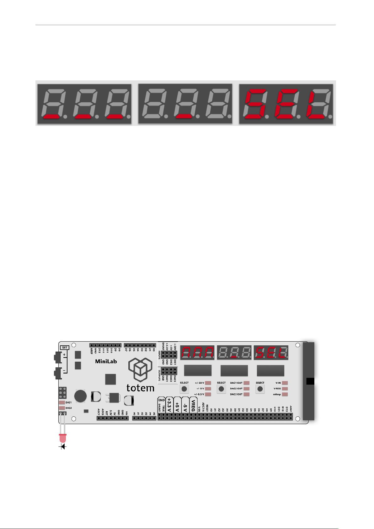
Example
1. Enter pulse generation mode, select continuous pulse mode with following parameters:
Period = 30,000 µs
Pulse width = 15,000 µs
2. Enable infinite pulse mode by pressing corresponding mode button,
3. Connect generators output to an LED.
4. Observe that LED blinks, experiment by changing pulse width and see that LED dims
or brightens. Now you’ve got a working PWM module.
!
Fig. 26 Example pulse generation
! of !21 31
Page 22

www.totemmaker.net
Totem MiniLab
Programming with MiniLab
Second part of the MiniLab is contained in a TotemDuino board. It is a fully backwards
with Arduino UNO platform, so all the great Arduino IDE can be used to write firmware
for TotemDuino as well. In this chapter a quick guide on setting up MiniLab to be used
with Arduino IDE will be presented, together with short example usage cases.
Connecting MiniLab to your computer
Using a mini USB cable you can upload new firmware sketches into TotemDuino. It holds
a complete backwards software compatibility with Arduino UNO boards, so Arduino IDE
can be used to write programs for it. While you can use different programming
environments to write firmware for it, using Arduino is one of the most friendliest and
quickest way to start.
Firstly, install Arduino IDE to your computer — refer to official documentation for the
Arduino IDE installation instructions, which can be found here:
https://arduino.cc/en/Guide/HomePage
Additional learning and introductory resources is recommended to use, such as:
• What is an Arduino?
https://learn.sparkfun.com/tutorials/what-is-an-arduino
• What is a circuit?
http://learn.sparkfun.com/tutorials/what-is-a-circuit
While TotemDuino works without any additional drivers with Windows10, previous
versions of Windows might require manually downloading drivers for a communication
chip used in it (PL-2303HXD). A latest version can be found at manufacturers website:
http://www.prolific.com.tw/US/ShowProduct.aspx?p_id=225&pcid=41
On macOS systems, driver will need to be manually installed for it to work:
http://www.prolific.com.tw/US/ShowProduct.aspx?p_id=229&pcid=41
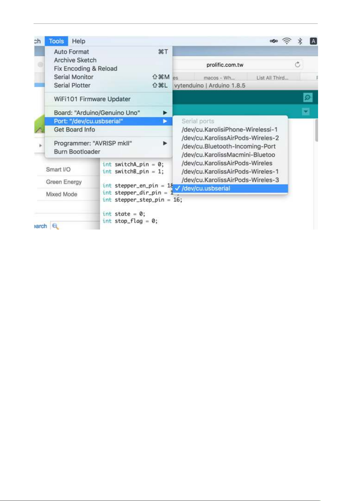
After installation, TotemDuino serial port /dev/cu.usbserial should show up when
connected:
! of !22 31
Page 23
www.totemmaker.net
Totem MiniLab
!
Fig. 27 Selecting TotemDuino board port
One note regarding macOS compatibility is that it’s important to not unplug the device
while it’s being programmed. Doing so will cause the driver to get stuck, and further
connected TotemDuino boards will not show up until computer is restarted.
On most Linux systems driver for the TotemDuino should be included in the system
already, so no further steps are needed to be taken. If it’s missing, or the device doesn’t
enumerate when connected, refer to your distribution manual on how to enable PL2303
kernel module. Tested distributions that include the driver are Debian (and derivatives
such as Ubuntu) and Fedora.
Using Arduino IDE
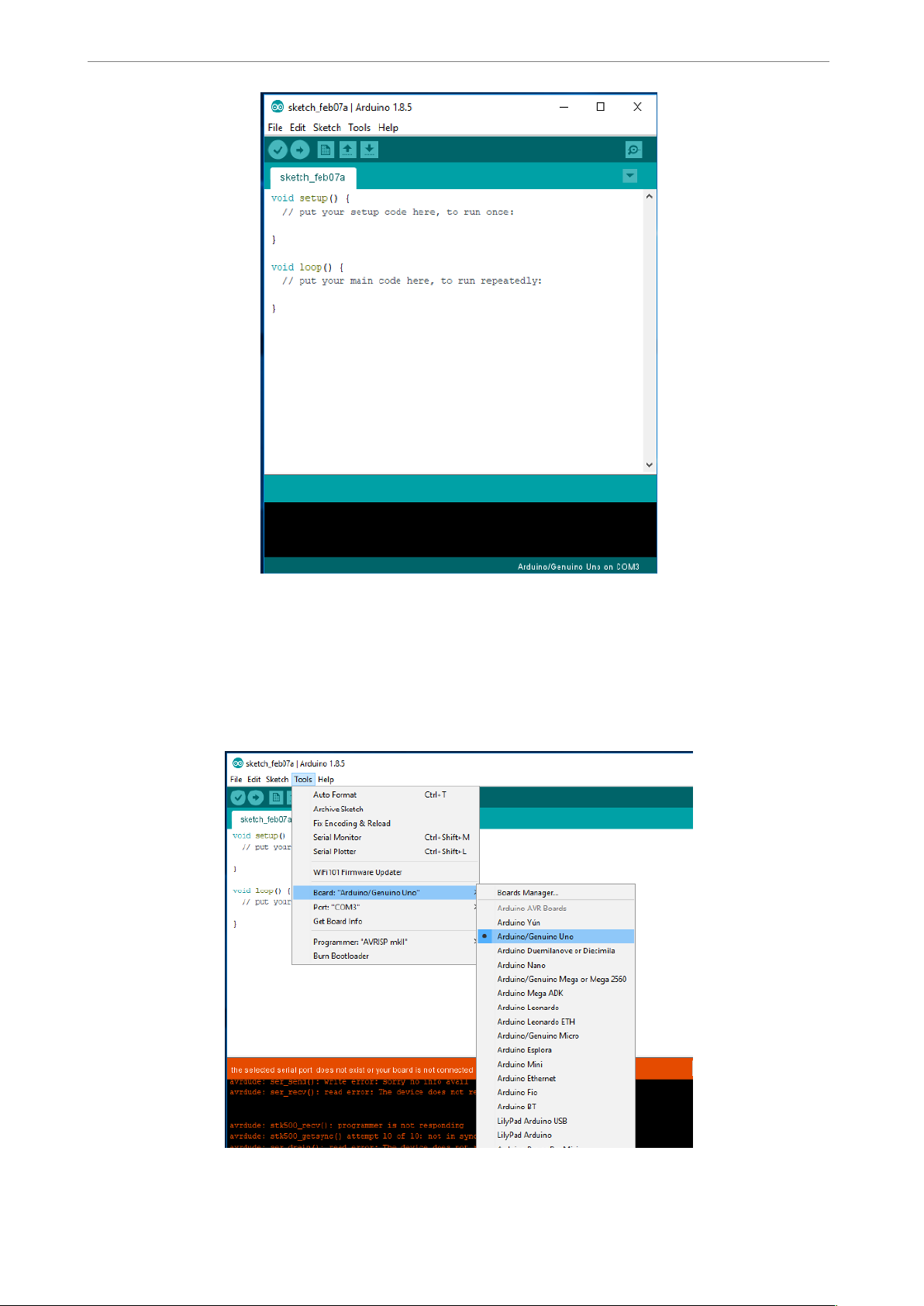
After installation, you should be greeted by default Arduino IDE window:
! of !23 31
Page 24
www.totemmaker.net
Totem MiniLab
!
Fig. 28 Arduino IDE window
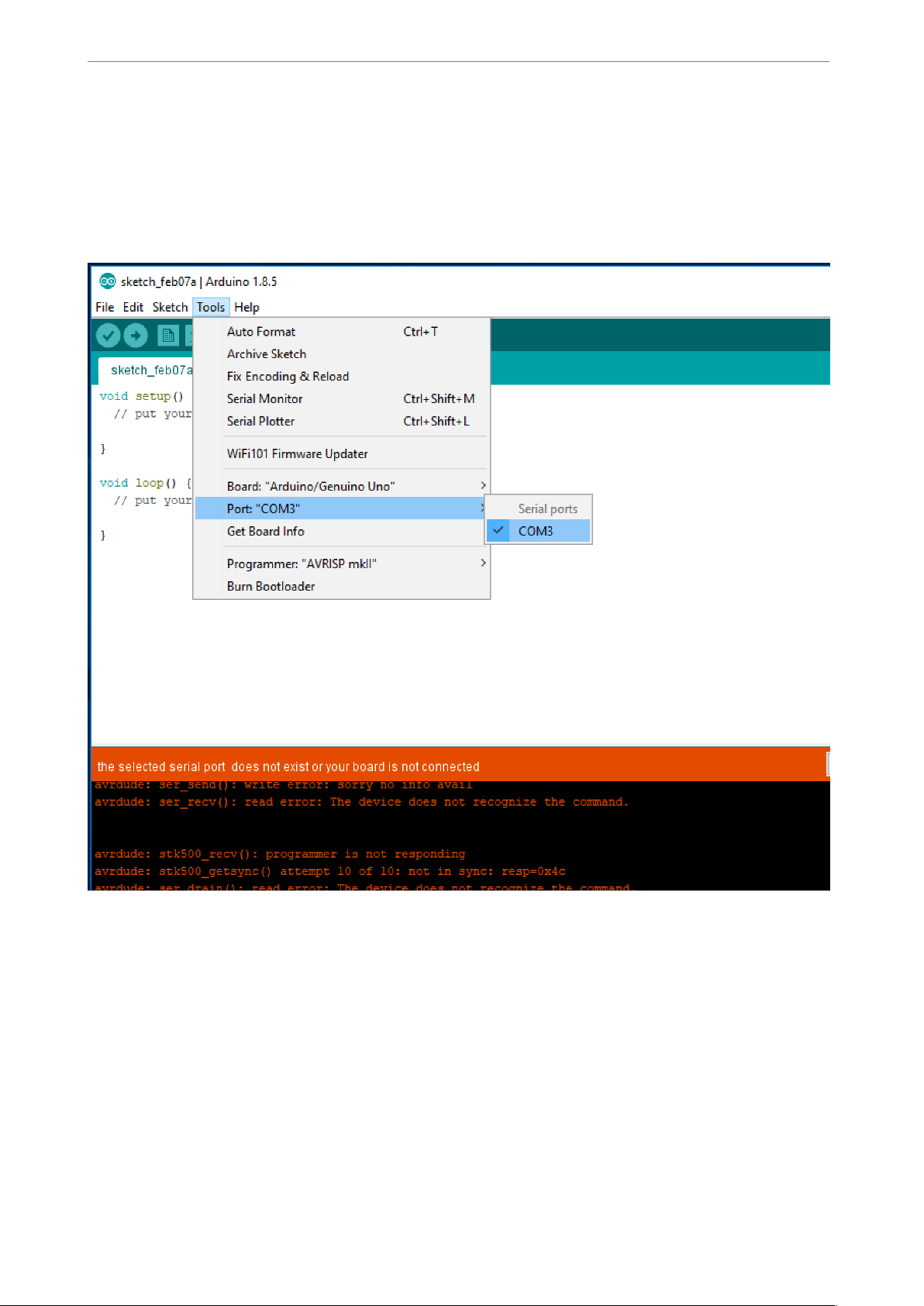
To work with TotemDuino, first you must choose the correct board for which code will be
compiled, as well serial port, by which the compiled firmware will be uploaded to it. You
can select the board by clicking Tools-> Board. In the drop-down menu, please select
Arduino/Genuino UNO board:
!
Fig.29 Board selection
! of !24 31
Page 25
www.totemmaker.net
Totem MiniLab
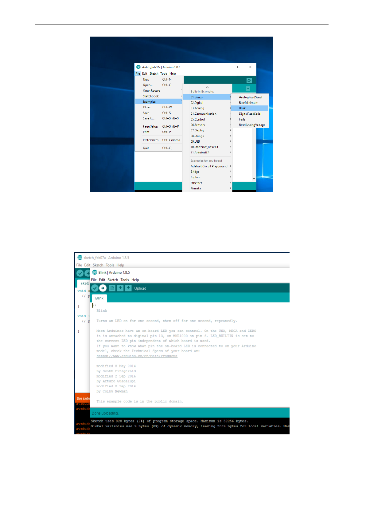
Next, we’ll select serial port. Because the number of available serial ports differ from one
computer to another, and there’s no way to know which port is the correct TotemDuino
one, you might need to follow this procedure. First check what ports are available when
TotemDuino is disconnected, and compare the list once you connect TotemDuino back.
The newly appeared port will be the port that should be used. On most laptops there are
no extra serial ports, so you might see TotemDuino port as being the only one available.
!
Fig. 30 Selecting TotemDuino serial port
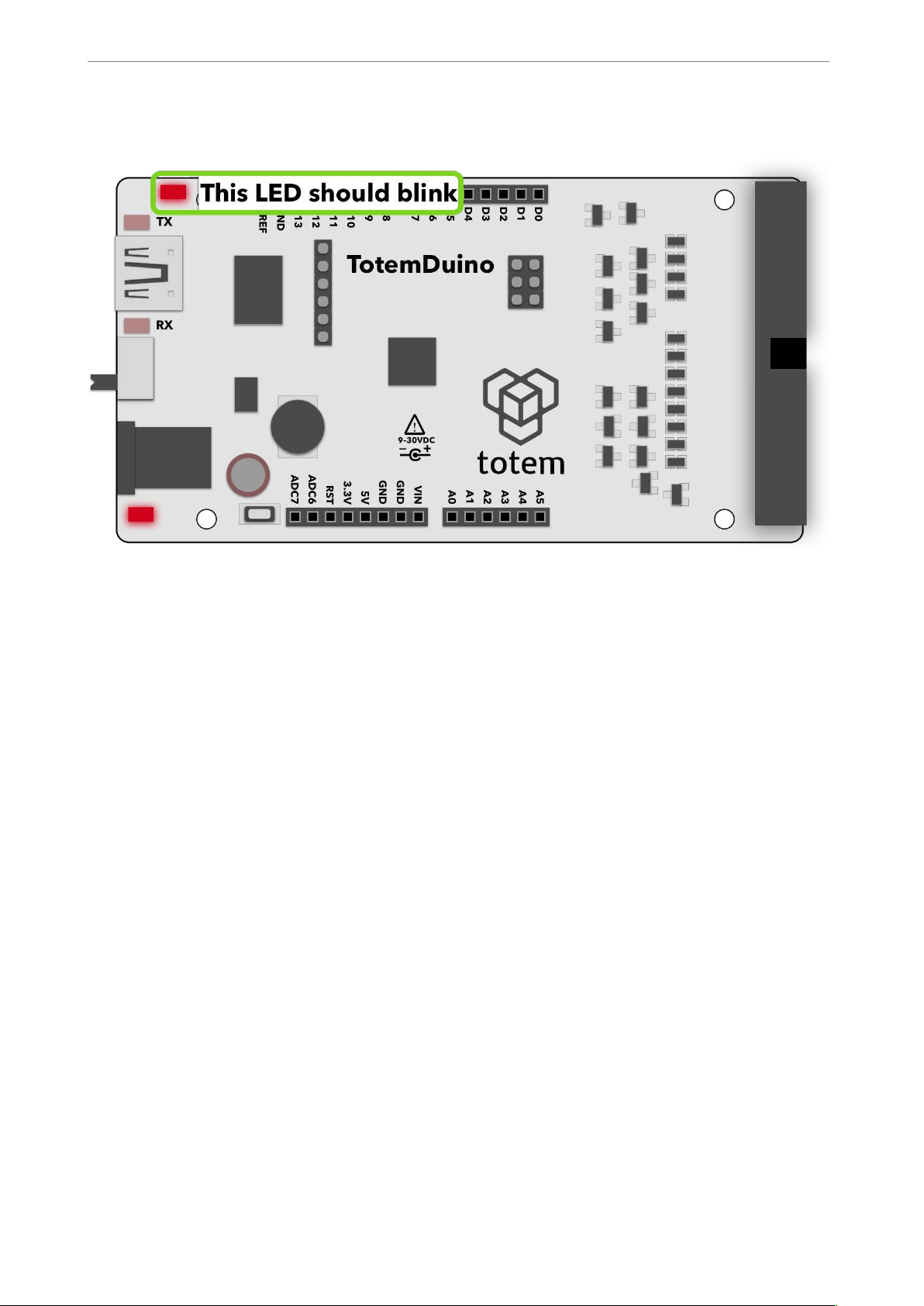
Once that’s done, we can start writing firmware for it. As always, its best to start with the
basics, so first we should try to upload a simplest firmware which only blinks the onboard
LED on the TotemDuino.
Using File->Examples->01. Basics drop-down menu select Blink example firmware:
! of !25 31
Page 26
www.totemmaker.net
Totem MiniLab
!
Fig. 31 Selecting example firmware
This will open a new Arduino IDE window with the source code of that firmware. Try to
compile and write the firmware to TotemDuino by clicking Upload button (icon with
right arrow):
!
Fig. 32 Uploading firmware successfully
! of !26 31
Page 27
www.totemmaker.net
Totem MiniLab
You should see a notification “Done uploading” in the bottom status bar. Now check if the
firmware does what it’s supposed to:
!
Fig.33 Example LED blink firmware
If the LED blinks, you got every bit working! Now you can start diving into the world of
programming by exploring other examples or creating your own firmwares for it. You
could plug external sensors, shields to bring even the craziest ideas to life.
TotemDuino tightly integrates with LabBoard, so it can help you debug problems with
your code, measure the output signal frequency, pulses, or the LabBoard could be used as
an input device, generating needed test signals for your TotemDuino.
Have fun!
! of !27 31
Page 28
www.totemmaker.net
Totem MiniLab
Expanding MiniLab
In this chapter several options on how to get even more from the MiniLab are discussed.
We hope that this will give you a jumpstart of your own ideas on where else you could use
your MiniLab. As MiniLab is a flexible and an always improving system, we would like to
hear your opinions! Please write what you feel is missing (or could be improved!) from the
MiniLab to [email protected]
Using breadboards
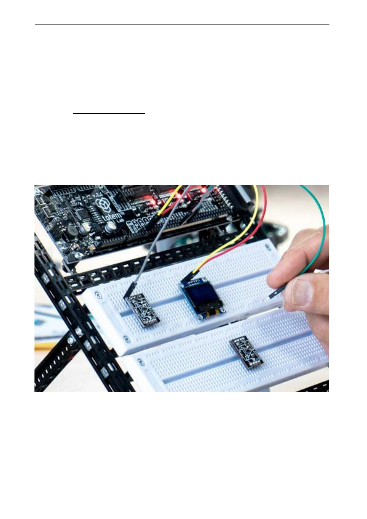
In the MiniLab kit you will find several breadboards, that together with easily accessible
MiniLab connections, arranged in a row can be accessed in a clean manner:
Fig. 34 Breadboard use in MiniLab
We suggest you to build the workbench from Totem construction parts where the
breadboards are mounted just bellow the LabBoard, so it helps not only with the
“containment” of the work area, but also gets rid of relative motion between breadboards
and external components in more advanced use cases. This helps to prevent accidental
wire disconnects which takes long time to find and creates a frustrating experience.
! of !28 31
Page 29
www.totemmaker.net
Totem MiniLab
Side panels
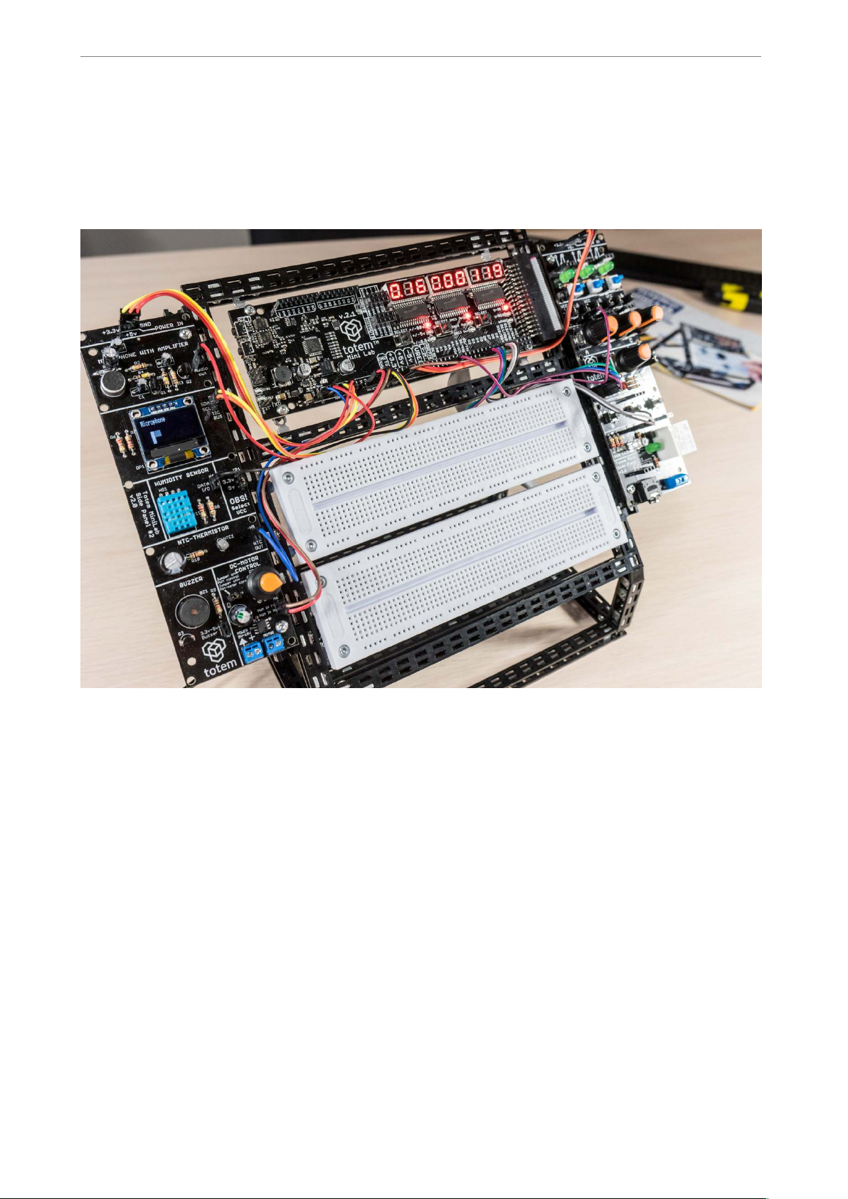
While MiniLab will work on its own, but you can easily expand it with side panels. A side
panel is a collection of basic most commonly used electronics blocks that can be used
together with MiniLab to even further extends it’s abilities.
!
Fig. 35 Side panels
In the side panels you’ll find:
• Switches, buttons
• Potentiometers
• Rotary encoder
• Relay module
• RGB full color LED
• Graphical OLED module
• Microphone module with integrated preamplifier
• Humidity sensor
• NTC temperature sensor
! of !29 31
Page 30

www.totemmaker.net
Totem MiniLab
• Buzzer
• H-bridge DC motor driver
Together with each side panels you’ll get a quick start guide on how to work with each of
the module in the side panel together with code samples. While modules in side panels are
indented to be self-contained and not rely on one another, this gives you a chance to
experiment on integrating parts of it to build a connected system — as an example you
could program it to control the DC motor by rotating the potentiometer and displaying the
current value on the OLED screen or making a sound-activated relay switch.
Totem is always expanding the list of side panels that are designed to interface with
MiniLab. Please check www.totemmaker.net for the latest list of their abilities and
documentation. Together with documentation you’ll be able to get drivers and sample
firmware for each module of each side panel, so you can easily include them in your
experiments.
! of !30 31
Page 31

www.totemmaker.net
Totem MiniLab
What’s next
After getting to know MiniLab, you can expand it to your own wishes! Using MiniLab
together with breadboards, you can easily experiment with new sensors, drivers and many
more electronic devices, and measure or supply your own generated signals from
LabBoard.
We hope that you’ll never run out of inspiration while using MiniLab. For more ideas and
projects, you’re always welcome at http://totemmaker.net for new tutorials, projects and
more!
! of !31 31
 Loading...