

Page 1
Mini Lab
Audio Side panel
Side Panel 3
Totem by UAB Aldrea
ver 1.1
Page 2
www.totemmaker.net
Mini Lab Audio Side Panel
Overview
This is a getting started guide for the third expansion board for the Totem Mini Lab
system. This board focuses attention to the analog audio side of electronics, and contains
an enclosed, fully self-sufficient audio generation, visualisation and output loop.
In this document we’ll go over all of the available modules in the board, together with
explanations on their interface with the Mini Lab as well as usage examples.
Side panels are meant to bring easy access to commonly used components that are
difficult to wire on breadboards due to their dimensions, or require additional equipment
to operate them. Side panels give a plug and play interface that lets users to concentrate
on experiments or learning, rather than spending time solving issues on how to interface
with the part.
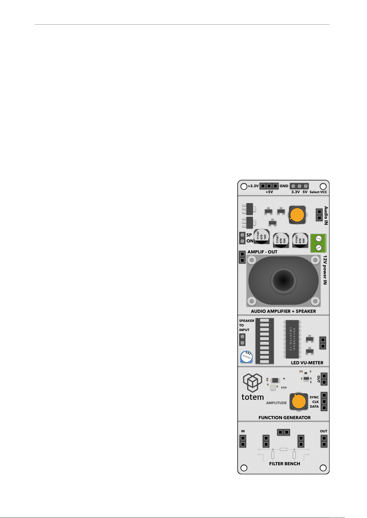
This document is divided into sections where each separate
module is described. In the side panel 3 these modules are
available for use:
• Audio amplifier with speaker — AB class discrete
audio amplifier with integrated loudspeaker. Can route
amplified audio signal either to the speaker or to external
sink via breadboard pins. Capable of outputting up to 1 W
of RMS power. Works with 12 V voltage source.
• LED VU-meter — Audio signal volume unit (VU) with
10 bar LED display. Works in approximately 3dB/step, 30
dB range. Has an integrated sensitivity adjustment
potentiometer
• Function generator — sine, square and triangle wave
generator capable of outputting up to 12.5 MHz signals.
Output amplitude can be adjusted with integrated
potentiometer, and generator can be controlled through
digital interface.
• Filter bench — simple pi-filter prototyping module,
where you can quickly prototype and experiment with
different filters. It’s designed to take in regular THT
components, such as resistors, capacitors and inductors
in the three available spaces. The effect on signals can be
immediately observed with neighbouring audio amplifier.
of 2 10
Page 3
www.totemmaker.net
Mini Lab Audio Side Panel
Modules
In the board only the supply power is shared between modules. Otherwise they’re fully
isolated from one another, and can be used independently. Logic level for digital signals
have a jumper which selects the boards to work either at 3.3 or 5 V logic level. It’s
important for the side panel to have the same logic level as the controller board (e.g.,
TotemDuino), for best results.
Audio amplifier with speaker
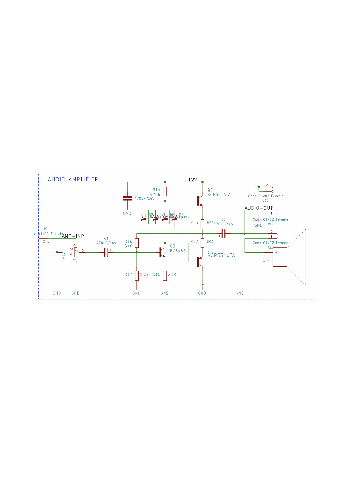
This is an AB class discrete audio amplifier module, capable of up to 1 W output RMS
power. Module is designed to work from externally applied 12 V line with connector J1 or
contact terminal H6. Input volume is adjusted with potentiometer P1.
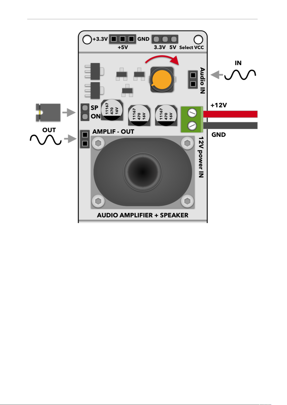
Inbuilt speaker is enabled by connecting a jumper to JP2 connector, amplified signal
output can be connected with a H4 female connector.
You can use the function generator as a signal source (described below) by just connecting
a jumper cable between amplifier input and generator output. Another possible input
source is using Totem side panel 1 microphone module.
While the amplifier will work in a wide input voltage range, the upper voltage limit is 12 V.
You can use the same 12 V used to power Mini Lab by connecting into VIN line on the
Mini Lab board.
Fig. 1 Audio amplifier schematic.
of 3 10
Page 4
www.totemmaker.net
Mini Lab Audio Side Panel
VU Meter
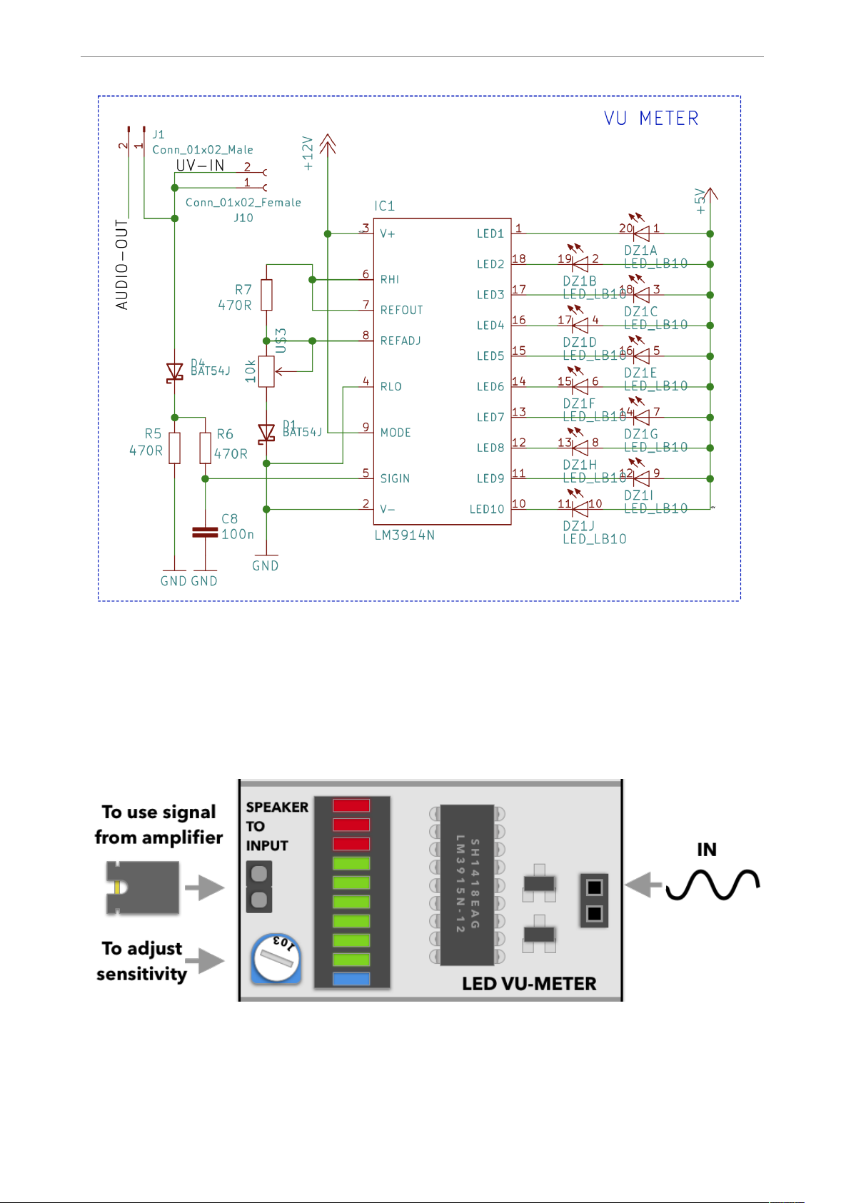
An Audio Volumetric Unit (VU) meter module is relying on a 10-bar LED display as an
output. Each bar represents a 3dB change in the input signal level. The module shares the
same 12 V voltage supply line as the audio amplifier module described above.
Fig. 2 Using amplifier module.
of 4 10
Page 5
www.totemmaker.net
Mini Lab Audio Side Panel
Input signal level sensitivity can be adjusted by potentiometer U$3. We suggest that
before using the module a calibration sequence be performed — apply the maximum
allowed input signal to the module, and turn the potentiometer until all LED are lit, except
top 3 which are red. During use lit red LEDs will then indicate overload of the input level.
Fig. 3 VU meter schematic.
Fig. 4 Using VU meter.
of 5 10
Page 6
www.totemmaker.net
Mini Lab Audio Side Panel
Function generator
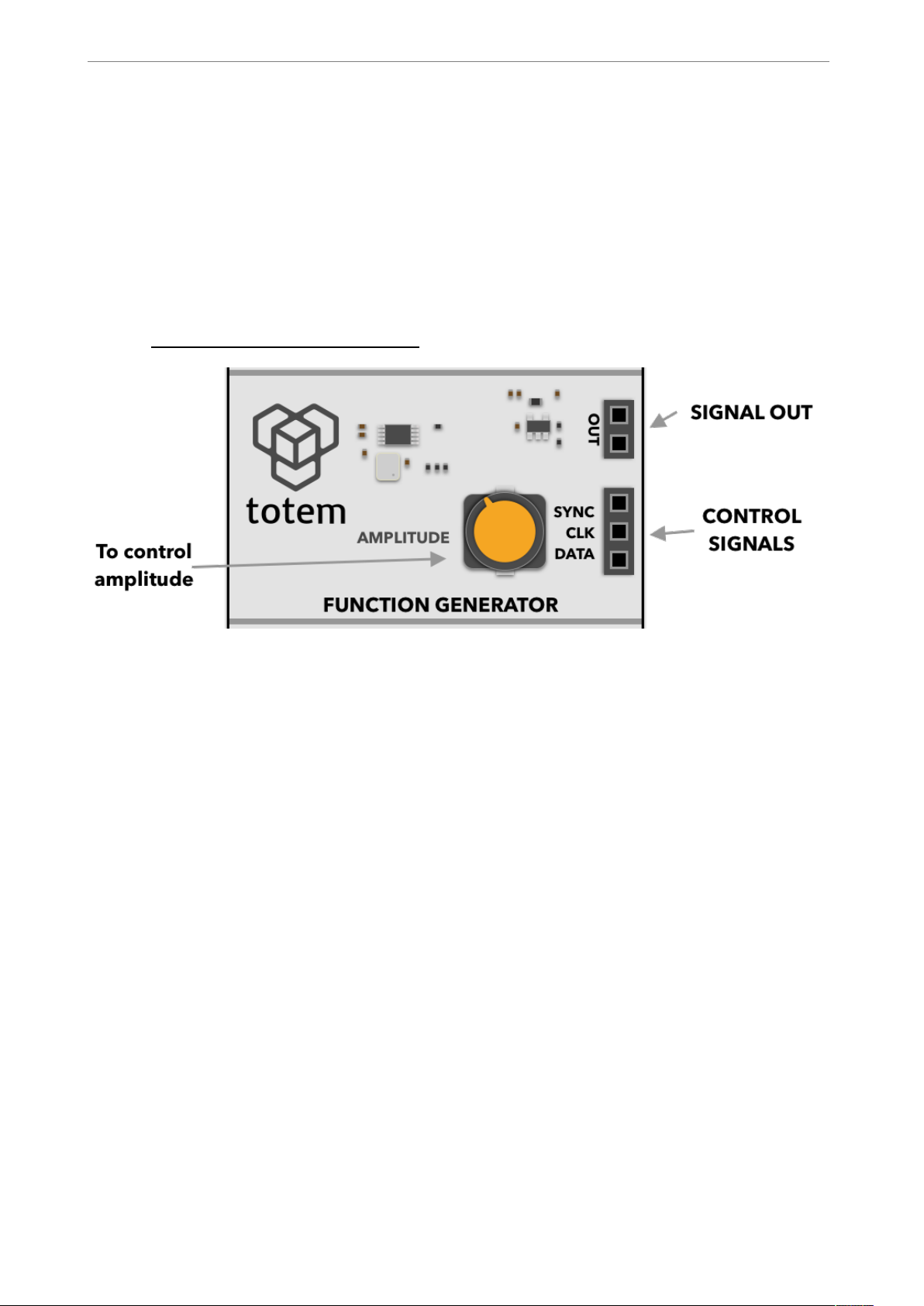
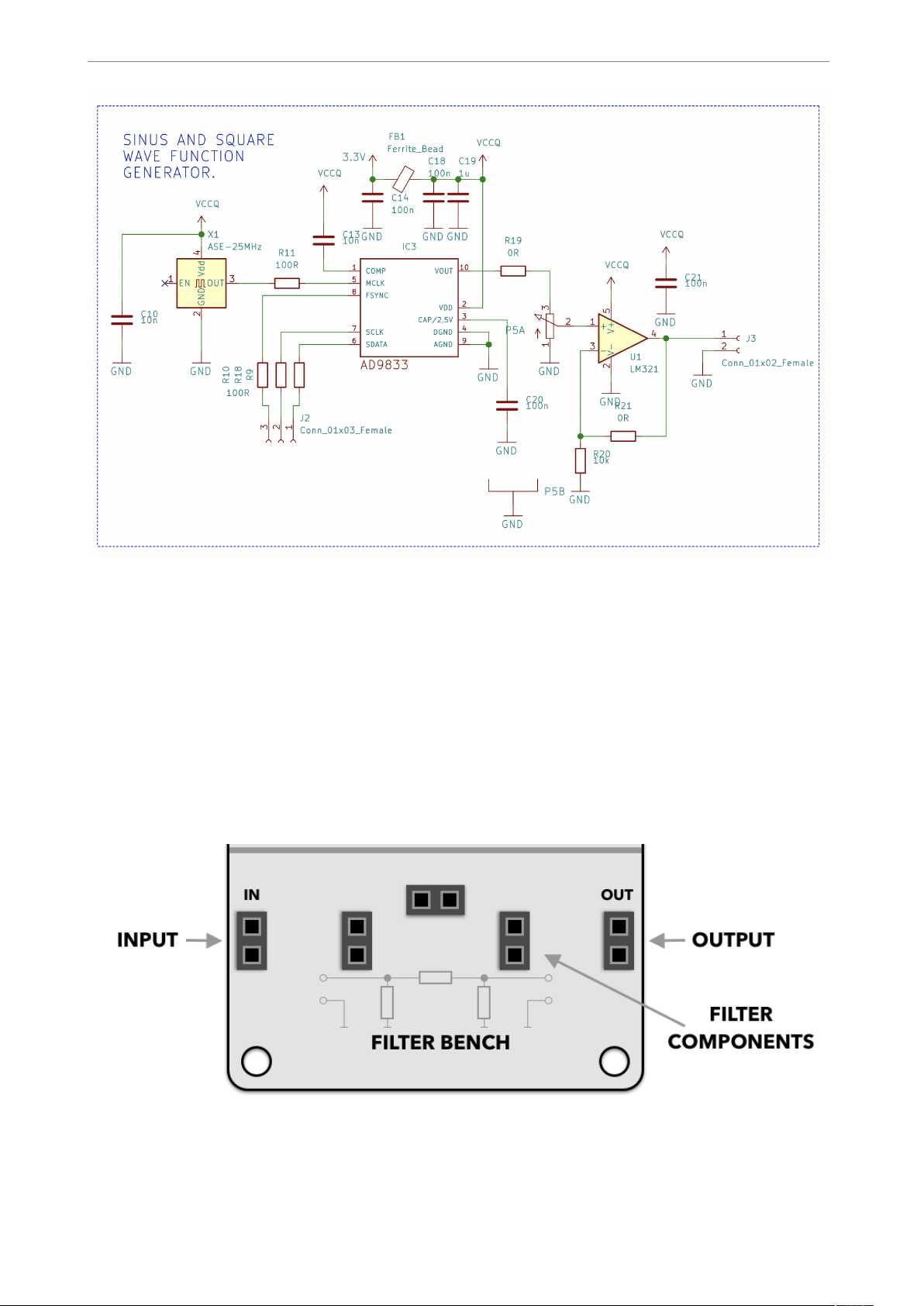
This module consists of a digitally controlled function generator AD9833 chip. It is
capable to generate sine, triangle and square wave output signal in up to 12.5 MHz
frequency. Generated signal is buffered with an operation amplifier, giving user the ability
to control output signal amplitude.
We suggest to use and supply sample library to communicate with generator chip from
TotemDuino microcontroller board. For the latest version of it please check out our gitlab
page at https://github.com/totemmaker.
Output of the function generator can be wired to the input of audio amplifier, allowing you
to hear the output of if with no extra parts. Additionally, filter bench module can be placed
between those modules to also experiment with pi-filters, and its effect to the signal.
Fig. 6 Using function generator.
of 6 10
Page 7
www.totemmaker.net
Mini Lab Audio Side Panel
Filter Bench
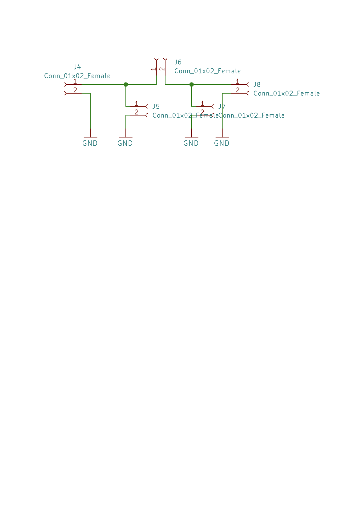
This is a simple framework for experimenting with pi-type filters. It allows you to easily
connect different THT components, such as resistors, capacitors and inductors. Filter
bench module is meant to be used as middle module between signal generator and audio
amplifier modules, allowing user to quickly experience the effect that various components
has on the signal.
Fig. 5 Function generator schematic.
Fig. 7 Using filter bench.
of 7 10
Page 8
www.totemmaker.net
Mini Lab Audio Side Panel
Fig. 7 Filter bench schematic
of 8 10
Page 9
www.totemmaker.net
Mini Lab Audio Side Panel
Mounting
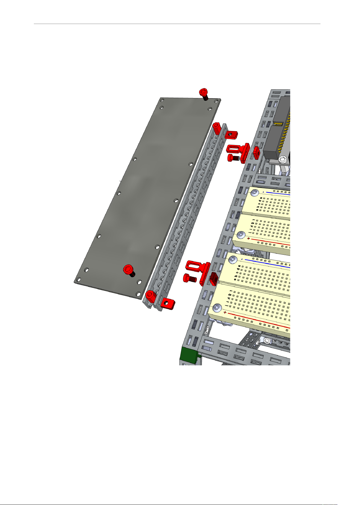
We suggest using the following guide for side panel mounting to the Mini Lab workbench:
In this case, the sub-assembly can be easily taken off by sliding the pins from the sockets.
If a more permanent assembly is needed, nuts and screws can be used to fix the sidepanel
in place.
Fig. 8 Side panel mounting to the Mini Lab
of 9 10
Page 10
www.totemmaker.net
Mini Lab Audio Side Panel
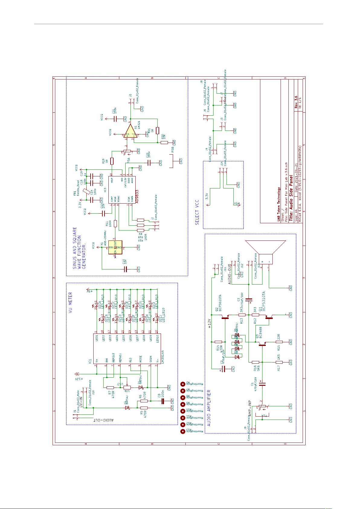
Schematic
of 10 10
 Loading...