

Page 1

TM-P2BXATVA User’s Manual
Introduction
A. Specifications
System Chipset VIA 692/693 chipset.
CPU Intel Pentium II processors, support
233/266/300/333 (Ex. Clk 66MHz) MHz.
300/350/400/ 450/ 500 (Ex. Clk 100MHz) MHz
Memory Expandable to 768MB (3 banks) with three 168-
pin DIMM socket {support 3.3 V EDO (66MHz
only) / SDRAM (66MHz/ 100MHz)}.
I/O Winbond 83977, two high speed 16550
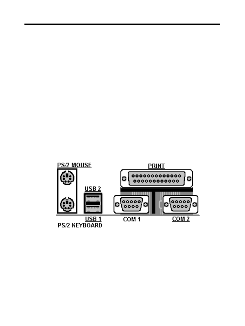
compatible serial ports, one Multi-Mode.
Parallel Port support SPP/EPP/ECP standard
mode.
Two onboard PCI IDE Ports (32-bit data transfer).
LS-120/ ZIP FDD, IrDA/ ASK IR/ Consumer IR.
Dual USB ports
Support two 360/720KB/1.2/1.44/2.88MB floppy
disk devices.
One PS/2 Mouse port.
BIOS Award System BIOS installed in socket (Flash
and PnP).
Expansion slots One AGP slot, five PCI Master Slots and two 16-
bit ISA Slots.
Voltage Auto 1.8V-3.5V
Dimension 4-layer PCB, size (22cm x 20cm).
Others Support BIOS setting CPU type (Jumper-less),
CPU Auto Temperature Sensor & Music Alarm,
voltage monitor and CPU Fan monitor, Bus
Master/ Ultra DMA/33, ACPI, AGP Bus, Keyboard
Power On, PS/2 Mouse Power On, Modem Ring
On, LAN wake up, Debug display on board.
1
Page 2
TM-P2BXATVA User’s Manual
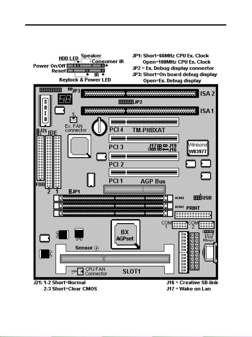
Setup Guide
A. Layout Diagram
2
Page 3
TM-P2BXATVA User’s Manual
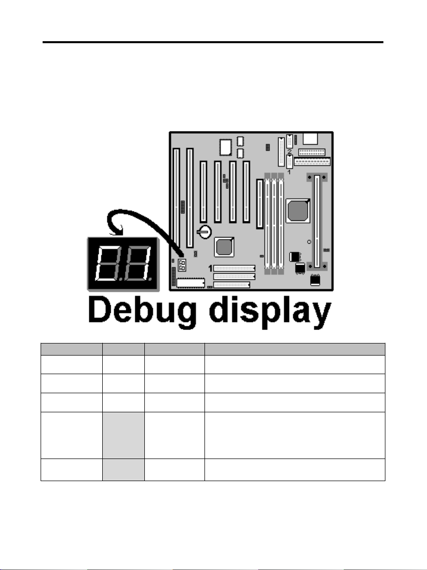
B. Smart Display On Board
When the CPU, DRAM, Cache RAM, FDD or VGA card have not been
properly installed, user can isolate those basic problems through the Debug
display and instructions from the manual. To Professional system engineers
or maintenance engineers, the Debug display can work as an 80 Port Debug
Card.
Error code Display Message Solution
C1 None
Can’t detect
DRAM
1. Reinstall or replace the SDRAM.
2. Reinstall or replace the BIOS.
C6 None
Can’t detect
DRAM
1. Reinstall or replace the SDRAM.
2. Reinstall or replace the BIOS.
OD None
Can’t detect
VGA card
1. Reinstall or replace the VGA card.
2. Replace the BIOS.
4E Yes
Can’t detect
Floppy disk
1. Replace the BIOS. (if no screen)
2. Enter the BIOS Setup menu to reset.
3. Check that the FDD cable and the power
connector are properly connected.
4. Reconnect the FDD cable or replace the FDD.
61 Yes
L2 cache
problem
1. Enter BIOS Setup to disable the external
cache.
3
Page 4
TM-P2BXATVA User’s Manual
C. CPU Voltage and Frequencies
ROM PCI/ISA BIOS (2A69KTJA)
CHIPSET FEATURE SETUP
AWARD SOFTWARE, INC
Auto Configuration : Enabled Auto Detect DIMM/ PCI Clk : Enabled
EDO DRAM Speed Selection : 60ns Spread Spectrum : Disabled
EDO CASx# MA Wait State : 2 CPU Speed : Manual
EDO RASx# Wait State : 2 CPU Ratio : X 2.5
SDRAM RAS-to CAS Delay : 3 CPU Frequency : 100 MHz
SDRAM RAS Precharge
Time
: 3 Spread Spectrum : Disabled
SDRAM CAS latency Time : Auto CPU Warning Temperature : Disabled
SDRAM Precharge Control : Disabled Current CPU Temperature : 28℃/ 82℉
DRAM Data Integrity Mode : Non-ECC Current SYSFAN Speed :4285 RPM
System BIOS Cacheable : Enabled Current CPUFAN Speed :4000 RPM
Video BIOS Cacheable : Enabled Current Vin3 (V) : 2.88V
Video RAM Cacheable : Disabled
8 Bit I/O Recovery Time : 1
16 Bit I/O Recovery Time : 1
Memory Hole At 15M-16M : Disabled
Esc : Quit Selection : Item
Passive Release : Enabled F1 : Help PU/PD/+/- : Modify
Delayed Transaction AGP
Aperture Size (MB)
: Disabled
: 64
F5 : Old Values (Shift) F2 : Color
F6 : Load BIOS Default
F7 : Load Setup Default
Dear Customers:
Thank you for your patronage of our products. The board you bought is a
jumper-less mainboard. The ratio and frequency of the CPU shall be set in
BIOS and the working voltage for the CPU shall be automatically detected.
Please read carefully the following instructions:
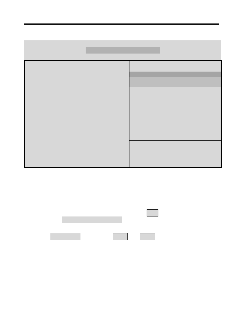
1. Power on the installed system and press the "DEL" key to enter BIOS
Setup. Select "Chipset Features Setup" and press <Enter>.
2. Select "CPU Speed" and press "PgUp" or "PgDn" to set the CPU ratio
and frequency. The available options are Intel PII
233MHz (66X3.5), 266MHz (66X4), 300MHz (66X4.5), 333MHz (66X5),
366MHz (66X5.5), 400MHz(66X6), 433MHz(66X6.5), 466MHz(66X7),
500MHz(66X7.5).
250MHz(100X2.5), 300MHz(100X3), 350MHz(100X3.5), 400MHz(100X4),
450MHz(100X4.5), 500MHz(100X5), 550MHz(100X5.5), 600MHz(100X6)
4
Page 5
TM-P2BXATVA User’s Manual
and "Manual".
To set the CPU manually, please note the following:
CPU Speed: "Manual" (you can manually set the CPU ratio and frequency)
CPU Ratios: x3.5, x4, x4.5, x5, x5.5, x6, x6.5, x7, x7.5
CPU Frequency: 66, 68, 75, 83, 100, 103, 112, 133Mhz
Several options are provided for the CPU external clock. You are
recommended to restore to the default setting in case of instability when the
external clock exceeds 66MHz.
NOTE: System failure may occur if the CPU frequency is set incorrectly. To
solve this problem. Press the "Insert" key on the keyboard to clear the
previously set frequency (i. c., restore the default frequency), and then
reboot the system.
Switch voltage is applied, making the temperature lower and voltage
steadier.
You don’t need to adjust Voltage in Pentium II mainboard. It will
automatically send out one VID (Voltage Identification) to the mainboard
power supply to ask for the voltage it needs.
The CPU type default setting is Intel Pentium II 250MHz=100 MHz*
2.5.
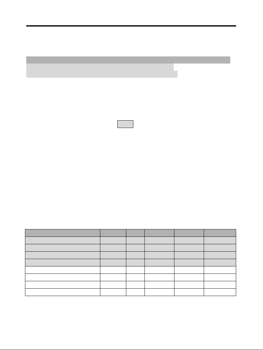
Intel Pentium II CPU family
CPU Ext. clk Ratio L1 cache L2 cache Package
Intel Pentium II – 450MHz 100MHz X4.5 32KB 512KB SECC 1
Intel Pentium II – 400MHz 100MHz X4 32KB 512KB SECC 1
Intel Pentium II – 350MHz 100MHz X3.5 32KB 512KB SECC 1/ 2
Intel Pentium II – 300MHz 100MHz X3 32KB 512KB SECC 1
Intel Pentium II – 333MHz 66MHz X5 32KB 512KB SECC 1
Intel Pentium II – 300MHz 66MHz X4.5 32KB 512KB SECC 1
Intel Pentium II – 266MHz 66MHz X4 32KB 512KB SECC 1
Intel Pentium II – 233MHz 66MHz X3.5 32KB 512KB SECC 1
5
Page 6
TM-P2BXATVA User’s Manual
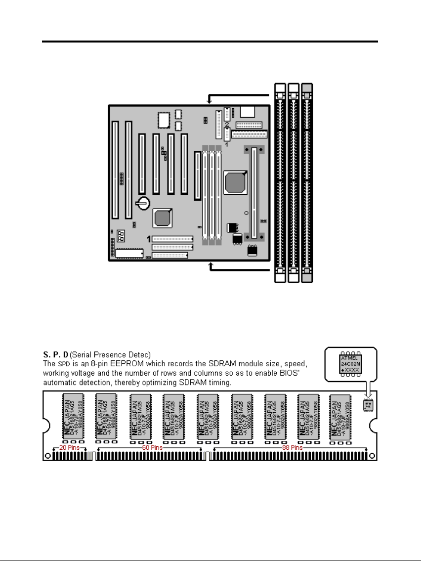
D. EDO/ SDRAM Installation Procedures:
A 168-pin DIMM can support up to 768MB 3.3V EDO (66MHz) /
SDRAM (66MHz/ 100MHz).
You are recommended to use SDRAMs. With SPD that are compliant
with PC-100. This will enable BIOS to detect the SDRAM speed,
thereby fully bring into play the efficiency of the SDRAM.
To avoid compatibility and reliability problems, you are recommended to
test the 168-pin SDRAMs before buying them since the PCB
6
Page 7
TM-P2BXATVA User’s Manual
specifications differ.
First, verify the working voltage of the EDO/ SDRAM module in either
DIMM socket.
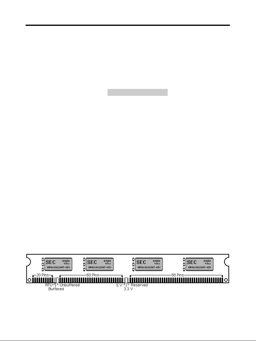
P2BXAT only supports 3.3V EDO/ SDRAM module. The following
illustration shows you the difference between 3.3V and 5V to ensure
your correct selection of 3.3V DIMM module for using.
You can set up the BIOS “Chipset Feature Setup” to the best working
condition basing on the type of EDO/ SDRAM you are using.
The BIOS DRAM default setting is 60 ns. Change the BIOS “Chipset
Feature Setup” default setting to 50ns for better performance, if the
chipset is marked 50ns.
Change nothing if EDO RAM is used. BIOS automatically detect the
RAM type.
MEMO for Installing System:
⊕ Concerning memory setup, you can find how to from “Chipset
Feature Setup” under BIOS setup. However, to avoid system unstable
or system hang, user without engineering background is not suggested
to change BIOS set up.
⊕ If system boot failure, please clean DIMM socket (with clean oil) or
polish Gold-Finger of DRAM with soft eraser, and try again.
The Dual Inline Memory Module (DIMM) must be 3.3 Volt and
Unbuffered Synchronous DRAM (SDRAM) 8MB, 16MB, 32MB, 64MB,
128MB or 256MB. The following illustration shows the type of DIMM
Module.
168-PIN SDRAM DIMM Notch Key Definitions
7
Page 8
TM-P2BXATVA User’s Manual
E. Keyboard/ PS/2 Mouse Power On and MODEM Ring on
To make sure the 5VSB signal nearly to 750mA (Amperage) from
ATX Power Supply, or if your keyboard consuming power than
300mA, it's better to upgrade your ATX Power Supply to 1A for
working perfectly.
If you are going to use the function of keyboard and PS/2 mouse power on,
then, the power-switch will be becoming useless automatically (unable to be
used).
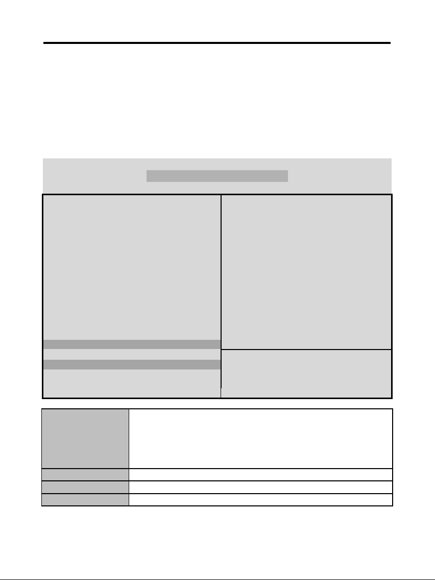
ROM PC/ISA BIOS (2A69KTJA)
INTEGRATED PERIPHERALS
AWARD SOFTWARE, INC.
IDE HDD Block Mode : Enabled Onboard Serial Port 2 : 2F8H / IRQ3
IDE Primary Master PIO : AUTO UART Mode Select : Normal
IDE Primary Slave PIO : AUTO
IDE Secondary Master PIO : AUTO Onboard Parallel Port : 378H/IRQ 7
IDE Secondary Slave PIO : AUTO Parallel Port Mode : ECP+EPP
IDE Primary Master UDMA : AUTO ECP Mode Use DMA : 3
IDE Primary Slave UDMA : AUTO EPP Mode Select : EPP 1.9
IDE Secondary Master
UDMA
: AUTO
IDE Secondary Slave UDMA : AUTO
On-Chip Primary PCI IDE : Enabled
On-Chip Secondary PCI IDE : Enabled
USB Keyboard Support : Disabled
Init Display First : AGP
POWER ON Function : Hot KEY
Esc : Quit Selection : Item
Hot Key Power ON : Ctrl-F12 F1 : Help PU/PD/+/- : Modify
KBC input clock : 8MHz F5 : Old Values (Shift)F2 : Color
Onboard FDC Controller : Enabled F6 : Load BIOS Default
Onboard Serial Port 1 : 3F8H / IRQ4 F7 : Load Setup Default
Hot KEY When user select this option, it will show another line
lines as Hot Key Power ON: Ctrl-
F(1/2/3/4/5/6/7/8/9/10/11/12) select any you like. After
power off, if user key in the "Ctrl-F?", it will power on the
system.
PS/2 Mouse Left It will power on the system by PS/2 mouse left.
PS/2 Mouse Right It will power on the system by PS/2 mouse Right.
Button Only Only the power button can power on the system.
8
Page 9
TM-P2BXATVA User’s Manual
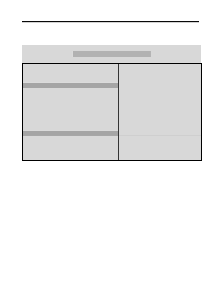
Modem Ring On Function Operation:
ROM PCI / ISA BIOS (2A69KTJA)
POWER MANAGEMENT SETUP
AWARD SOFTWARE, INC
Power Management : Disabled ** Reload Global Timer Events **
PM Control by APM : No IRQ[3-7, 9-15], NMI : Enabled
Video Off Method : V/H SYNC+Blank Primary IDE 0 : Disabled
Video Off After : Standby Primary IDE 1 : Disabled
MODEM Use IRQ : 3 Secondary IDE 0 : Disabled
Doze Mode : Disabled Secondary IDE 1 : Disabled
Standby Mode : Disabled Floppy Disk : Disabled
Suspend Mode : Disabled Serial Port : Enabled
HDD Power Down : Disabled Parallel Port : Disabled
Throttle Duty Cycle : 62.5%
ZZ Active in Suspend : Disabled
VGA Active Monitor : Enabled
Soft-Off by PWR-BTTN : Instant-Off
CPUFAN Off In Suspend : Enabled
Resume by Ring : Enabled
IRQ 8 Clock Event : Disabled
Esc : Quit Selection Item
F1 : Help PU/PD/+/- : Modify
F5 : Old Values (Shift) F2 : Color
F6 : Load BIOS Default
F7 : Load Setup Default
1. Have an external MODEM connected to COM 1 or COM 2.
2. Enter BIOS setup.
3. Select Power Management Setup.
4. This number of MODEM use IRQ has to be set as same as the IRQ of
Serial Port which you are connecting in. Please set in N/A if you are
not going to use the function of MODEM ring on.
5. Resume by Ring: Enable.
6. Save BIOS setup and Reboot.
7. Booting from DOS, Windows, or Windows 95.
8. Turn off the system by:
a. ATX-Power Switch
b. Windows 95 Software Power Off
9. System Waiting for Modem Ring On
When Modem Ringing Signal Active, System will wake-up.
9
Page 10
TM-P2BXATVA User’s Manual
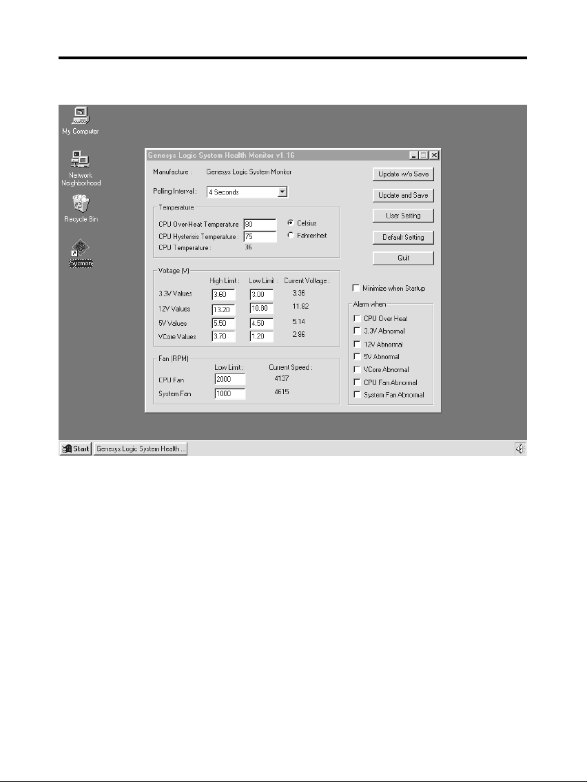
F. System Health Monitor
Fan Monitoring:
There are two fan connectors, one is for CPU, the other can be a
housing fan. When the fans speed is working abnormal, there will be
warning (Speaker Alarm) through application software such as
SM10(Small Icon for System Monitoring) to notify user. The fan
monitoring function is implemented by connecting fan to 3-pin fan
connector FAN1/ FAN2 and installing SM10. Referring to Page 10
(System Health Monitor).
10
Page 11
TM-P2BXATVA User’s Manual
CPU Thermal Protection:
TM-P2BXAT implements special thermal protection circuits. When
temperature is higher than a predefined value, there will be warning
(Speaker Alarm) through application software such as SM10 (Small
Icon for System Monitor) to notify user. It's automatically implemented
by BIOS or SMD10, no hardware installation is needed. Referring to
Page10 (System Health Monitor).
System Voltage Monitoring:
TM-P2BXAT is featured with a voltage monitoring system. When you
turn on your system, this smart design will keep on monitoring your
system working voltage. If any of voltage is over the component's
standard, there will be Speaker Alarm though application software
SM10 (Small Icon for System Monitor) for a warning to user. System
voltage monitoring function monitors 5V, 12V, 3.3V and CPU voltage.
It's automatically implemented by BIOS and SM10, no hardware
installation is needed. Referring to Page 10 (System Health Monitor)
11
 Loading...