

Page 1

TM-586 IP2 User’s Manual
Introduction
A. Specifications
System Chipset Intel 82430 HX chipset.
CPU One 321-pin socket 7 for Intel Pentium
(P54C/CQS/ CS, P55C), AMD 5k86, K5, K6, Cyrix
6x86 (L, M2), IDT C6 processors, support 90/
100/ 120/ 133/ 150/ 166/ 180/ 200/ 233MHz.
Memory Expandable to 512MB (4 banks) with four 72-pin
SIMM sockets onboard (Support Fast Page Mode
and EDO DRAM ).
Cache 64-bit 256/ 512KB L2 Pipeline Burst SRAM
onboard or 160-pin COAST Module slot for 64-bit
256KB/ 512KB L2 SYNC. Cache Memory.
I/O SMC 37C665, two high speed 16550 compatible
serial ports, one Multi-Mode.
Parallel Port support SPP/EPP/ECP standard
mode.
Two onboard PCI IDE Ports (32 bit data transfer).
Support two 360/720KB/1.2/1.44/2.88MB floppy
disk devices.
One PS/2 Mouse port.
BIOS Award System BIOS installed in socket (Flash
and PnP).
Expansion slots Four PCI Master Slots and four 16-bit ISA Slots.
Dimension 4-layer PCB, 2/3 baby size (220mm x 280mm).
Others Windows 95 Compatible.
1
Page 2
TM-586 IP2 User’s Manual
Setup Guide
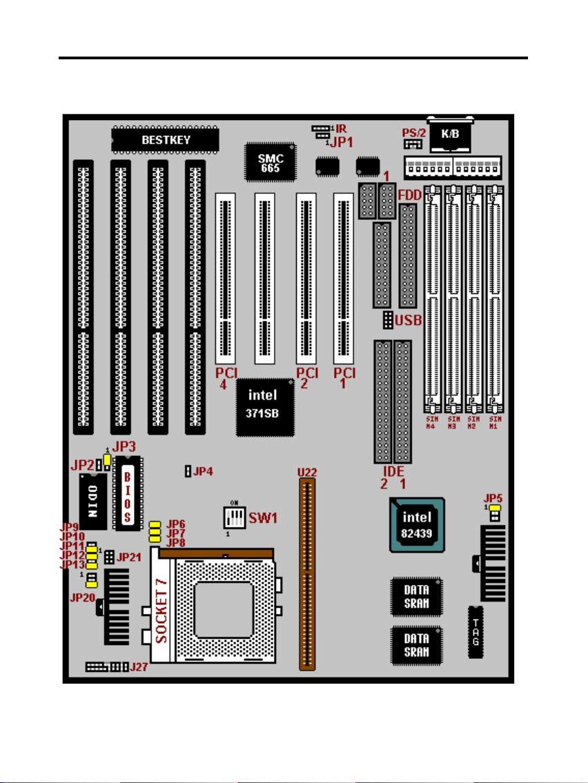
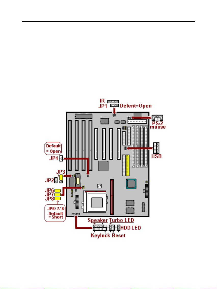
A. Layout Diagram
2
Page 3
TM-586 IP2 User’s Manual
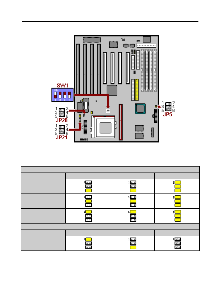
B. CPU Voltage Settings
All the voltage specifications adopted here are the averages of the
working voltage suggested by the CPU makers, to make any CPU
applied work with the best performance.
Pentium (P54C), AMD 5k86/ K5, Cyrix M1
JP5 JP20 JP21
3.6V
3.45V
3.3V
Pentium (P55C)
JP5 JP20 JP21
V I/O 3.3V
Vcore 2.8V
3
Page 4
TM-586 IP2 User’s Manual
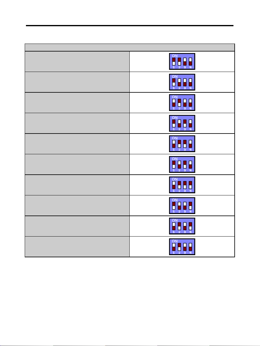
C. CPU Frequencies
SW1
Pentium - 75 MHz
Pentium - 90 MHz
Pentium - 100 MHz
Pentium - 120 MHz
Pentium - 133 MHz
Pentium - 150 MHz
Pentium - 166 MHz
Pentium - 180 MHz
Pentium - 200 MHz
Pentium - 233 MHz
The CPU type default setting is Intel Pentium 166MHz=66 MHz*2.5.
4
Page 5
TM-586 IP2 User’s Manual
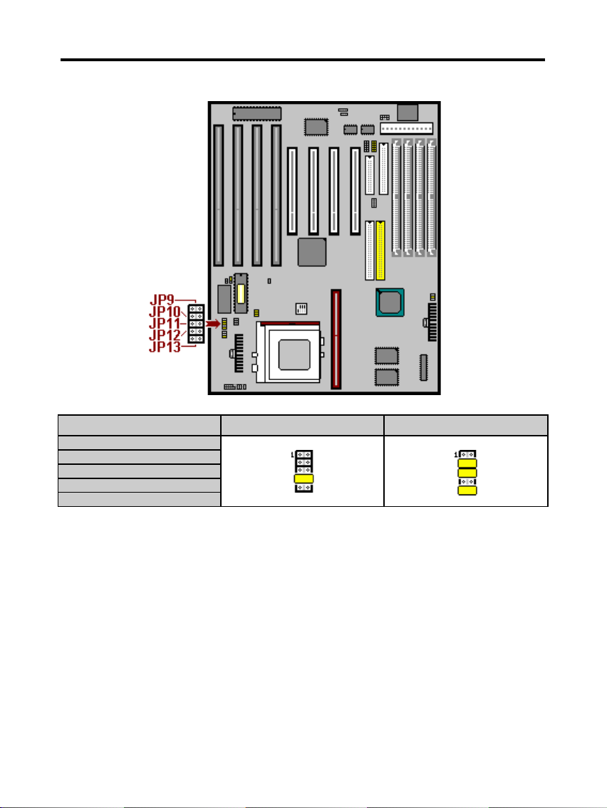
D. DRAM, EDO RAM Installation Procedures:
256K 512K
JP9
JP10
JP11
JP12
JP13
SIMM Socket output voltage is 5V, expandable to 512MB.
Support 5V Fast Page Mode/ Extended Data Out RAM.
The BIOS DRAM default setting is 70 ns. Change the BIOS “Chipset
Feature Setup” default setting to 60ns for better performance, if the
chipset is marked 60ns.
Change nothing if EDO RAM is used. BIOS automatically detects the
RAM type.
With 586 CPUs, two FPM/EDO RAM Modules are required on SIMM
5
Page 6
TM-586 IP2 User’s Manual
sockets to compose a bank for the system to start.
MEMO for Installing System:
⊕ Concerning memory setup, you can find how to from “Chipset
Feature Setup” under BIOS setup. However, to avoid system unstable
or system hang, user without engineering background is not suggested
to change BIOS set up.
⊕ If system boot failure, please clean SIMM socket (with clean oil) or
polish Gold-Finger of DRAM with soft eraser, and try again.
E. Other Jumper Settings
Speaker:
6
Page 7
TM-586 IP2 User’s Manual
Connect to the system’s speaker for beeping.
Keylock:
Keyboard lock switch and Power LED connector.
Reset:
Short to restart system.
HDD LED:
LED ON when onboard PCI IDE hard disk activates.
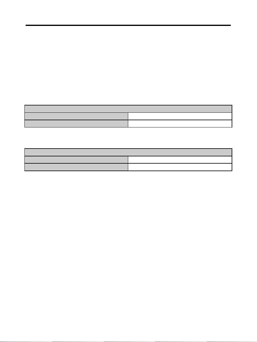
JP2: Clear CMOS
Turn off the system and short pins (JP2) to clear CMOS. Then open
pins before turning it on.
JP2
Open Normal operation (Default).
Short for clearing CMOS Data.
JP3: Flash BIOS voltage select
JP3
1-2 Short For 5V Flash BIOS
2-3 Short For 12V Flash BIOS
7
 Loading...