

Toshiba RBC-AX31W-UL, WX-TA01UES Owner's Manual
TOSH|BA
Carrier
REMOTE CONTROLLER FOR AIR CONDITIONER (SPLIT TYPE)
Owner's Manual
Remote Controller
Model name:
Wireless remote controller kit
RBC-AX31U(W)-UL
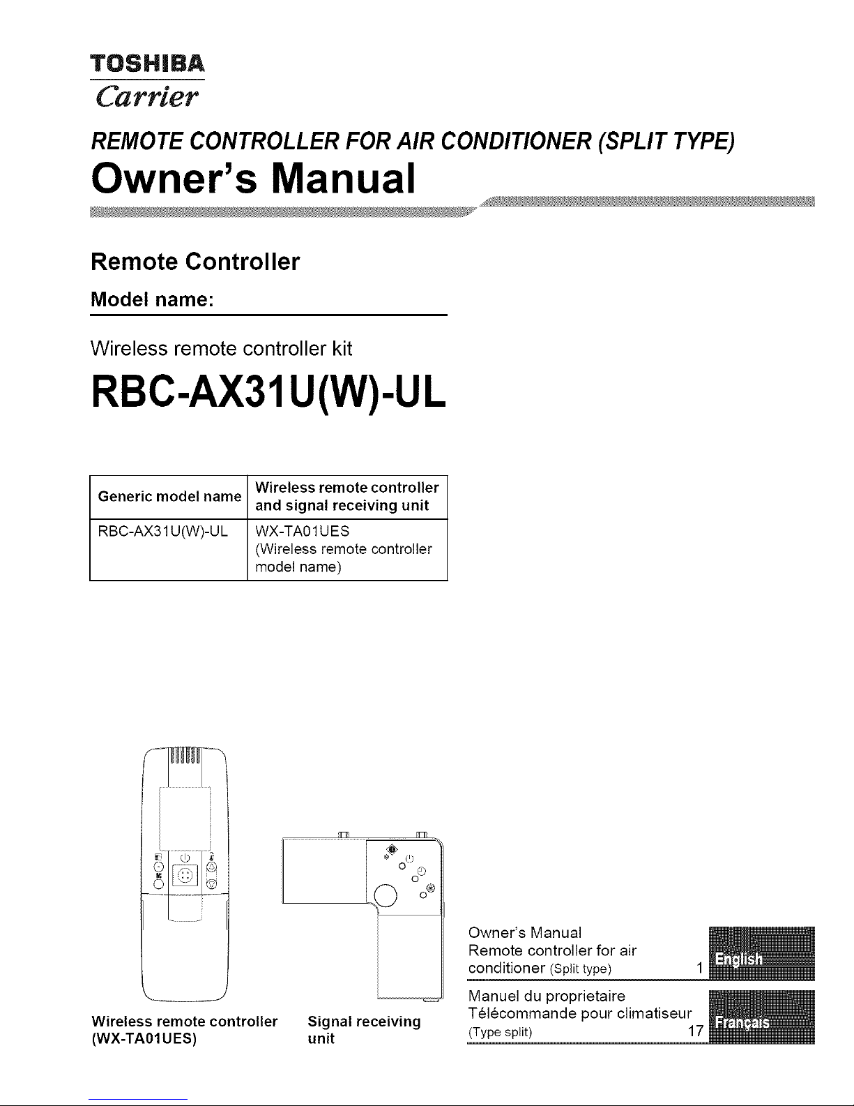
Wireless remote controller
Generic model name
and signal receiving unit
RBC-AX31U(W)-UL WX-TA01UES
(Wireless remote controller
model name)
Wireless remote controller
(WX-TA01 UES)
i :%'_oO
D o*
Signal receiving
unit
Owner's Manual
Remote controller for air
conditioner (Split type) 1
Manuel du proprietaire
Telecommande pour climatiseur
(Type split) 17
Wirelessremotecontrollerkit Owner'sManual
Thank you very much for purchasing TOSHIBA/Carrier Remote controller for Air
Conditioner.
Please read this owner's manual carefully before using your Remote controller for Air
Conditioner
• Be sure to obtain the "Owner's manual" and "Installation manual" from constructor (or
dealer).
Request to constructor or dealer
• Please clearly explain the contents of the Owner's manual and hand over it.
Contents
1 PRECAUTIONS FOR SAFETY ........................... 2
2 PART NAMES AND FUNCTIONS ......................... 3
3 CORRECT USAGE .................................... 7
4 TIMER OPERATION .................................... 9
5 HOW TO ADJUST AIR DIRECTION ...................... 10
6 SLIDE SWITCH ...................................... 11
7 HOW TO INSERT BATTERIES .......................... 11
8 HOW TO HANDLE THE REMOTE CONTROLLER ........... 12
9 HOW TO USE THE REMOTE CONTROLLER CORRECTLY... 13
10 ADDRESS .......................................... 14
11 HOW TO PERFORM EMERGENCY OPERATION ........... 15
12 BEFORE ASKING FOR REPAIR WORK .................. 16
-1-
Wireless remote controller kit Owner's Manual
1 PRECAUTIONS FOR SAFETY
WARNING
WARNINGS ABOUT INSTALLATION
• Make sure to ask the qualified installation professional in electric work to install the
remote controller.
If the remote controller is inappropriate installed by yourself, it may cause electric shock
or fire, etc.
• Make sure to install the air conditioner specified by TOSHIBA/Carrier and ask the
exclusive dealer when installing. If the air conditioner is installed by yourself, it may cause
electric shock or fire, etc.
WARNINGS ABOUT OPERATION
• Prevent any liquid from falling into the remote controller.
Do not spill juice, water or any kind of liquid.
It may cause malfunction, electric shock or fire, etc.
• When you are aware of any error with the air conditioner (smells like something burning,
etc.), immediately turn off the circuit breaker to stop the air conditioner, and make contact
with the dealer.
If the air conditioner is continuously operated with an error, it may cause malfunction,
electric shock or fire, etc.
WARNINGS ABOUT MOVEMENT AND REPAIR
• Do not repair any unit by yourself.
Whenever the air conditioner needs repair, make sure to ask the dealer to do it.
If it is repaired imperfectly, it may cause electric shock or fire, etc.
• When reinstalling the air conditioner, contact with the dealer.
If the installation is insufficient, it may cause electric shock or fire, etc.
Z_ CAUTION
CAUTIONS ABOUT INSTALLATION
• Do not install the remote controller in a place where its signals do not reach the indoor unit.
• Do not install the remote controller in the place under the direct sunlight and close to any
heat source. It may cause malfunction.
• The fluorescent lamp with rapid start system or inverter system may disturb the signal
reception. For details, contact with the dealer of the air conditioner you have purchased.
CAUTIONS ABOUT OPERATION
• Do not drop or apply strong shock to the air conditioner.
It may cause malfunction of the remote controller.
• Use batteries that meet the specifications.
- 2 - 2-EN

Wirelessremotecontrollerkit Owner'sManual
2 PART NAMES AND FUNCTIONS
• Remote Controller (WX-TA01UES)
• Up to 8 indoor units in a group can be controlled by one remote controller. (See page 14)
Illustration of LCD shown below is for explanation.
6
1 ,__-__ 11 7
I! _'U_OFI I 9
II _1 ........I.......
13 lO
4 11
17 12
7 !--18
8 13
1 Transmitting unit
15
2 ON/OFF button
Starts and stops the air conditioner
alternately. 16
3 Mode button 17
Selects desired operation mode.
4 Fan speed button
5 Timer set button
Used to setup the timer. (See page 9)
It may differ from the actual LCD.
Filter button
No function
ACL button
Used after batteries are replacedor theslide
switch is switched. (See page 11)
Slide switch (See page 11)
Battery compartment (See page 11)
Cover
Slide the cover downward holding its both
sides.
Remote controller sensor
Senses the ambient temperature when the
remote controller is selected with the sensor
button.
LCD
Displays the air conditioner operation mode.
(This illustration shows all display contents.)
AUTO louver display differs
according to the installed unit.
(See page 10)
Setup temperature button
Adjust the set point.
Set a desired set point by pushing _ @ or
@.
Swing/air direction button
(See page 10)
Address button (See page 14)
Ventilation button
Use this when a ventilation fan or other unit,
purchased on the market, has been
connected.
3-EN - 3 -
Wireless remote controller kit Owner's Manual
18 Sensor button
Selects the temperature sensor of the remote
controller.
The temperature sensor of the indoor unit is
selected by default. While the indoor unit
temperature sensor is selected, _ is
displayed on the display.
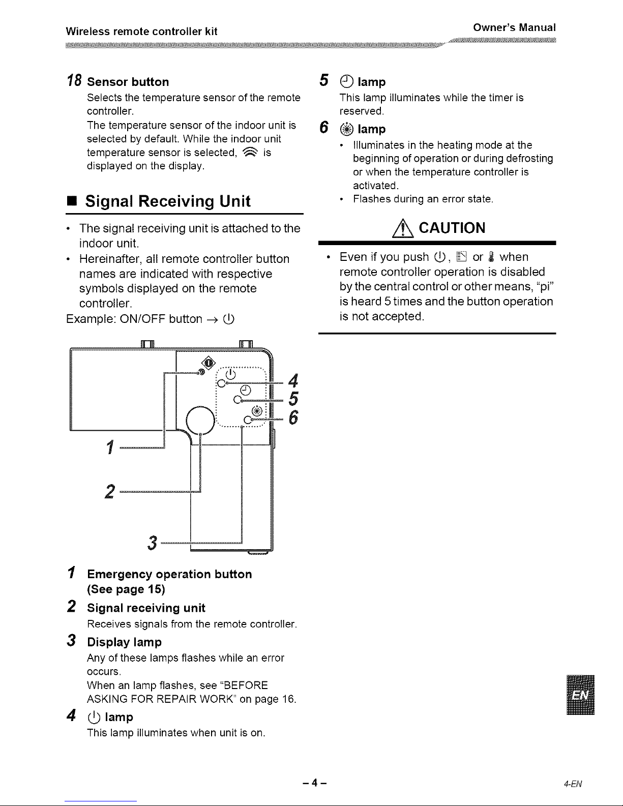
• Signal Receiving Unit
• The signal receiving unit is attached to the
indoor unit.
• Hereinafter, all remote controller button
names are indicated with respective
symbols displayed on the remote
controller.
Example: ON/OFF button _
[FIR
[
4
5
6
2
3
1 Emergency operation button
(See page 15)
2 Signal receiving unit
Receives signals from the remote controller.
3 Display lamp
Any of these lamps flashes while an error
OCCUrs.
When an lamp flashes, see "BEFORE
ASKING FOR REPAIR WORK" on page 16.
4 _ lamp
This lamp illuminates when unit is on.
5 C) lamp
This lamp illuminates while the timer is
reserved.
6 _ lamp
• Illuminates in the heating mode at the
beginning of operation or during defrosting
or when the temperature controller is
activated.
• Flashes during an error state.
/_ CAUTION
Even if you push _, _ or _ when
remote controller operation is disabled
by the central control or other means, "pi"
isheard 5times and the button operation
is not accepted.
- 4 - 4-EN
Wireless remote controller kit Owner's Manual
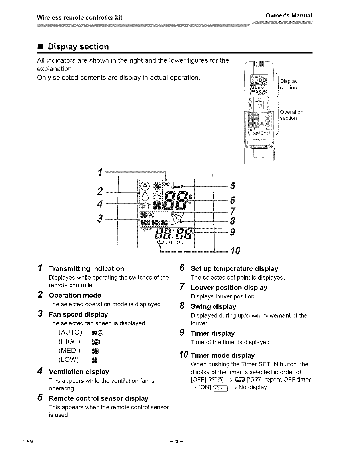
• Display section
All indicators are shown in the right and the lower figures for the
explanation.
Only selected contents are display in actual operation.
l isplay
section
Operation
section
1
2
4
3
1 Transmitting indication
Displayedwhile operatingthe switches of the
remote controller.
2 Operation mode
The selected operation mode isdisplayed.
3 Fan speed display
The selectedfan speed is displayed.
(AUTO) X@
(HIGH) R_
(MED.) X{
(LOW)
4 Ventilation display
This appears while the ventilation fan is
operating.
5 Remote control sensor display
This appearswhen the remotecontrolsensor
is used.
6 Set up temperature display
The selected set point is displayed.
7 Louver position display
Displays louver position.
8 Swing display
Displayed during up/down movement of the
louver.
9 Timer display
Time of the timer is displayed.
10
Timer mode display
When pushing the Timer SET IN button, the
display of the timer is selected in order of
[OFF] _ --> C.'_ _ repeat OFF timer
-->[ON] _ -->No display.
5-EN - 5 -
 Loading...