

Page 1

FILE NO. 110-200001
General Descriptions
Adjustment Procedures
Servicing diagrams
Part List
SERVICE MANUAL
NC MECHANICAL DECK
VIDEO CASSETTE RECORDER
W-708
General Descriptions
Adjustment Procedures
Servicing Diagrams
Parts List
Mar., 2000 Y
Page 2
SAFETY NOTICE
SAFETY PRECAUTIONS
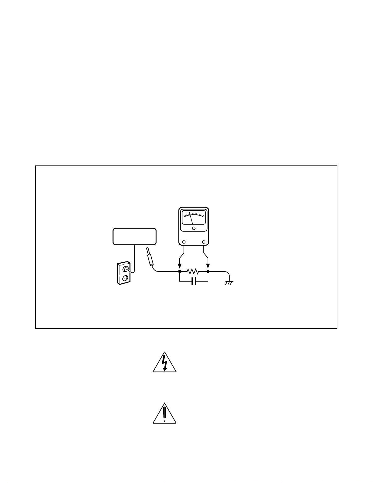
LEAKAGE CURRENT CHECK
Plug the AC line cord directly into a 120V AC outlet (do
not use an isolation transformer for this check). Use an
AC Voltmeter, having 5000 W per volt or more sensitivity. Connect a 1500 W 10 W resistor, paralleled by a
0.15 µF 150V AC capacitor between a known good
earth ground (water pipe, conduit, etc.) and all exposed metal parts of cabinet (antennas, handle
bracket, metal cabinet, screwheads, metal overlays,
control shafts, etc.).
READING SHOULD NOT EXCEED 0.3V
Measure the AC voltage across the 1500 W resistor.
The test must be conducted with the AC switch on and
then repeated with the AC switch off. The AC voltage
indicated by the meter may not exceed 0.3 V. A reading exceeding 0.3 V indicates that a dangerous potential exists, the fault must be located and corrected.
Repeat the above test with the VCR power plug
reversed.
NEVER RETURN A VCR TO THE CUSTOMER
WITHOUT TAKING NECESSARY CORRECTIVE
ACTION.
VIDEO CASSETTE
RECORDER
AC OUTLET
Test all exposed metal.
Voltmeter Hook-up for Leakage Current Check
1500 W
10 W
0.15µF 150V AC
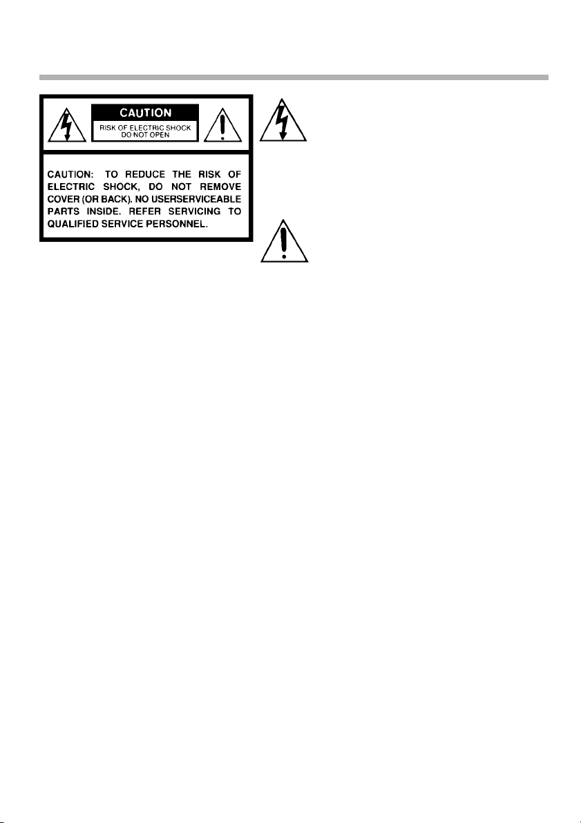
The lightning flash with arrowhead symbol, within an
equilateral triangle, is intended to alert the user to the
presence of uninsulated “dangerous voltage” within
the product's enclosure that may be of sufficient
magnitude to constitute a risk of electric shock to
persons.
AC VOL TMETER
(5000 W per volt or
more sensitivity)
Good earth ground
such as a water pipe,
conduit, etc.
The exclamation point within an equilateral triangle is
intended to alert the user to the presence of important
operating and maintenance (servicing) instructions
in the literature accompanying the appliance.
Page 3

Top
Parts List
Servicing Diagrams
Adjustment Procedures
Top
Adjustment Procedures
Servicing Diagrams
SECTION 1
GENERAL DESCRIPTIONS
1. OWNER'S MANUAL
Parts List
Page 4
Video Cassette Recorder
W-708
W-701
OWNER’S MANUAL
POWER
EJECT
PROG.TV
REC
PAUSE/STILL
REV FF
PLAY
STOP
This publication is printed
on recycled paper
70971842
Page 5
SAFETY PRECAUTIONS
The lightning flash with arrowhead symbol,
within an equilateral triangle, is intended to
alert the user to the presence of uninsulated “dangerous voltage” within the
product’s enclosure that may be of sufficient
magnitude to constitute a risk of electric
shock to persons.
The exclamation point within an equilateral
triangle is intended to alert the user to the
presence of important operating and
maintenance (servicing) instructions in the
literature accompanying the appliance.
WARNING: TO REDUCE THE RISK OF FIRE OR ELECTRIC SHOCK, DO NOT EXPOSE
THIS APPLIANCE TO RAIN
OR MOISTURE. DANGEROUS HIGH VOLTAGES ARE PRESENT INSIDE
THE ENCLOSURE. DO NOT OPEN THE CABINET. REFER SERVICING TO
QUALIFIED PERSONNEL ONLY.
CAUTION: TO PREVENT ELECTRIC SHOCK, MATCH WIDE BLADE OF PLUG TO
WIDE SLOT, FULLY INSERT.
Product Name: Video Cassette Recorder
Model Number: W-708/W-701
FCC Notice: “Declaration of Conformity”
This device complies with part 15 of the FCC Rules. Operation is subject to the
following two conditions: (1) This device may not cause harmful interference, and (2)
this device must accept any interference received, including interference that may
cause undesired operation.
Contact: Toshiba America Consumer Products, Inc.
Address: 1420 Toshiba Drive, Lebanon, TN37087
Telephone: 615-449-2360
User Installer Caution: Changes or modification made to this equipment not expressly
approved by Toshiba Corporation or parties authorized by Toshiba Corporation could
void the user’s authority to operate the equipment.
Note to CATV system installer:
This reminder is provided to call the CATV system installer’s attention to Article 820-40 of the
NEC that provides guidelines for proper grounding and, in particular, specifies that the cable
ground shall be connected to the grounding system of the building, as close to the point of cable
entry as practical.
2
Page 6
IMPORT ANT PRECAUTIONS
Save Original Packing Materials
The original shipping carton and packing materials will come in handy if you ever have to ship
your VCR. For maximum protection, repack the set as it was originally packed at the factory.
Avoid Volatile Liquid
Do not use volatile liquids, such as an insect spray, near the unit.
Do not leave rubber or plastic products touching the unit for a long time. They will mar the
finish.
Moisture Condensation
Never operate this unit immediately after moving it from a cold location to a warm location.
When the VCR is exposed to such a change in temperature, moisture may condense on the
cylinder inside, one of its most crucial internal parts. To prevent the VCR from possible
damage, do not use the unit for at least 2 hours when there is an extreme or sudden change
in temperature.
Compatibility
This video cassette recorder (VCR) is compatible with any other VCR bearing the
mark. HQ VHS equipment is also compatible with existing, non-HQ VHS equipment.
Copyright
It is permissible to record television programs, film, video tapes and other material only in the
event that third party copyrights and other rights are not violated.
INTRODUCTION
As an E
NERGY STAR
product model meets the E
®
Partner, TOSHIBA has determined that this product or
NERGY STAR
®
guidelines for energy efficiency.
In the spaces provided below, record the Model and Serial No. located at the rear of your video
cassette recorder.
Model No. Serial No.
Retain this information for future reference.
3
Page 7

IMPORTANT SAFETY
INSTRUCTIONS
CAUTION: PLEASE READ AND OBSERVE ALL WARNINGS AND INSTRUCTIONS
GIVEN IN THIS OWNER’S MANUAL AND THOSE MARKED ON THE UNIT.
RETAIN THIS BOOKLET FOR FUTURE REFERENCE.
This set has been designed and manufactured to assure personal safety. Improper use can
result in electric shock or fire hazard. The safeguards incorporated in this unit will protect
you if you observe the following procedures for installation, use and servicing. This unit is
fully transistorized and does not contain any parts that can be repaired by the user.
DO NOT REMOVE THE CABINET COVER, OR YOU MAY BE EXPOSED TO
DANGEROUS VOLTAGE. REFER SERVICING TO QUALIFIED SERVICE PERSONNEL
ONLY.
1. Read owner’s manual
After unpacking this product, read the owner’s manual carefully, and follow all
the operating and other instructions.
2. Power Sources
This product should be operated only from the type of power source indicated
on the marking label. If you are not sure of the type of power supply to your
home, consult your product dealer or local power company. For products
intended to operate from battery power, or other sources, refer to the operating
instructions.
3. Grounding or Polarization
This product may be equipped with a polarized alternating current line plug (a
plug having one blade wider than the other). This plug will fit into the power
outlet only one way. This is a safety feature. If you are unable to insert the plug
fully into the outlet, try reversing the plug. If the plug should still fail to fit, contact
your electrician to replace your obsolete outlet. Do not defeat the safety
purpose of the polarized plug.
4. Ventilation
Slots and openings in the cabinet are provided for ventilation and to ensure
reliable operation of the product and to protect it from overheating, and these
openings must not be blocked or covered. The openings should never be
blocked by placing the product on a bed, sofa, rug or other similar surface. This
product should not be placed in a built-in installation such as a bookcase or rack
unless proper ventilation is provided or the manufacturer’s instructions have
been adhered to.
5. Heat
The product should be situated away from heat sources such as radiators, heat
registers, stoves, or other products (including amplifiers) that produce heat.
4
Page 8
6. Water and Moisture
Do not use this product near water - for example, near a bath tub, wash bowl,
kitchen sink, or laundry tub; in a wet basement; or near a swimming pool and
the like.
7. Cleaning
Unplug this product from the wall outlet before cleaning. Do not use liquid
cleaners or aerosol cleaners. Use a damp cloth for cleaning.
8. Power-Cord Protection
Power-supply cords should be routed so that they are not likely to be walked
on or pinched by items placed upon or against them, paying particular attention
to cords at plugs, convenience receptacles, and the point where they exit from
the product.
9. Overloading
Do not overload wall outlets; extension cords, or integral convenience receptacles
as this can result in a risk of fire or electric shock.
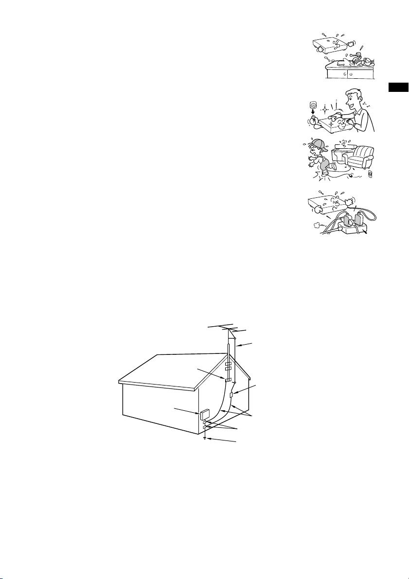
10. Outdoor Antenna Grounding
If an outside antenna or cable system is connected to the product, be sure the antenna or cable system
is grounded so as to provide some protection against voltage surges and built-up static charges. Article
810 of the National Electrical Code, ANSI/NFPA 70, provides information with regard to proper
grounding of the mast and supporting structure, grounding of the lead-in wire to an antenna discharge
unit, size of grounding conductors, location of antenna-discharge unit, connection to grounding
electrodes, and requirements for the grounding electrode.
EXAMPLE OF ANTENNA GROUNDING AS PER
NATIONAL ELECTRICAL CODE
ANTENNA
LEAD IN
WIRE
GROUND
CLAMP
ANTENNA
DISCHARGE UNIT
(NEC SECTION 810-20)
GROUNDING CONDUCTORS
(NEC SECTION 810-21)
GROUND CLAMPS
POWER SERVICE GROUNDING
ELECTRODE SYSTEM
(NEC ART 250, PART H)
S2898A
ELECTRIC
SERVICE
EQUIPMENT
NEC – NATIONAL ELECTRICAL CODE
INTRODUCTION
11. Power Lines
An outside antenna system should not be located in the vicinity of overhead power lines or other electric
light or power circuits, or where it can fall into such power lines or circuits. When installing an outside
antenna system, extreme care should be taken to keep from touching such power lines or circuits as
contact with them might be fatal.
5
Page 9
IMPORTANT SAFETY
INSTRUCTIONS
12. Lightning
For added protection for this product during storm, or when it is left unattended
and unused for long periods of time, unplug it from the wall outlet and
disconnect the antenna or cable system. This will prevent damage to the
product due to lightning and power-line surges.
13. Object and Liquid Entry
Never push objects of any kind into this product through openings as they may
touch dangerous voltage points or short-out parts that could result in a fire or
electric shock. Never spill liquid of any kind on the product.
14. Attachments
Do not use attachments not recommended by the product manufacturer as they may cause hazards.
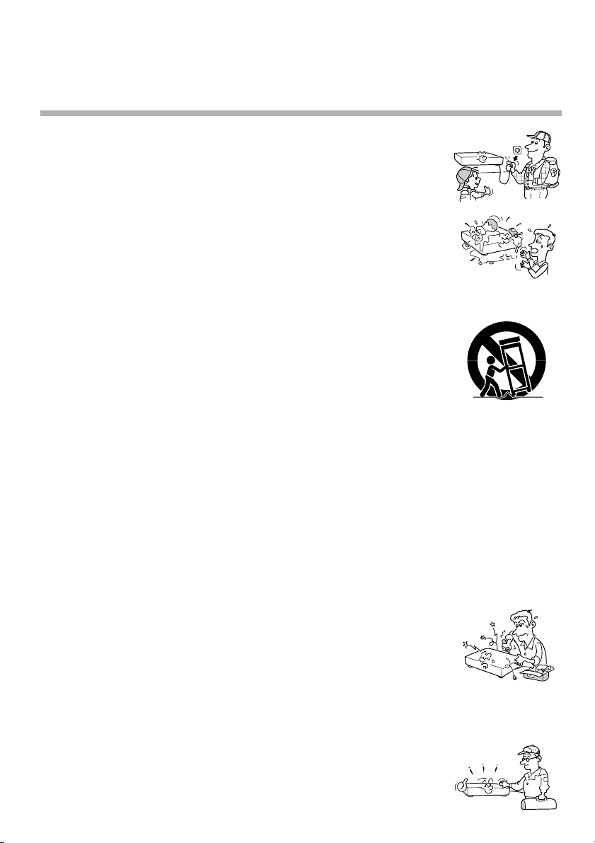
15. Accessories
Do not place this product on an unstable cart, stand, tripod, bracket, or table.
The product may fall, causing serious injury to a child or adult, and serious
damage to the product. Use only with a cart, stand, tripod, bracket, or table
recommended by the manufacturer, or sold with the product. Any mounting of
the product should follow the manufacturer’s instructions, and should use a
mounting accessory recommended by the manufacturer.
A product and cart combination should be moved with care. Quick stops,
excessive force, and uneven surfaces may cause the product and cart
combination to overturn.
16. Damage Requiring Service
Unplug this product from the wall outlet and refer servicing to qualified service personnel under the
following conditions:
a) When the power-supply cord or plug is damaged.
b) If liquid has been spilled, or objects have fallen into the product.
c) If the product has been exposed to rain or water.
d) If the product does not operate normally by following the operating instructions. Adjust only those
controls that are covered by the operating instructions as an improper adjustment of other controls
may result in damage and will often require extensive work by a qualified technician to restore the
product to its normal operation.
e) If the product has been dropped or damaged in any way.
f) When the product exhibits a distinct change in performance - this indicates a need for service.
S3125A
17. Servicing
Do not attempt to service this product yourself as opening or removing covers
may expose you to dangerous voltage or other hazards. Refer all servicing to
qualified service personnel.
18. Replacement Parts
When replacement parts are required, be sure the service technician has used replacement parts
specified by the manufacturer or have the same characteristics as the original part. Unauthorized
substitutions may result in fire, electric shock, or other hazards.
19. Safety Check
Upon completion of any service or repairs to this product, ask the service
technician to perform safety checks to determine that the product is in proper
operating condition.
6
Page 10

Contents
INTRODUCTION
Provides important notes and general
explanation of the VCR, including names of the
buttons, jacks, etc.
SAFETY PRECAUTIONS .................... 2
IMPORTANT PRECAUTIONS.............. 3
IMPORT ANT SAFETY
INSTRUCTIONS................................... 4
Contents .............................................. 7
Identification of Controls ................... 8
• Front Panel
• Remote Control
• VCR Display
• Rear Panel
PREPARATION
Explains what you need to do before operating
the VCR.
How to Use the Remote Control ...... 10
Connections ...................................... 11
Auto Set Up ....................................... 14
Initial Settings Using On-screen
Display ............................................... 15
• Setting the Language
• Optional settings on the SET UP
screen
• Setting the Clock
Storing Channels on the VCR .......... 17
Video Cassette Use .......................... 20
PLAYBACK
Explains variable functions concerning
playback.
Playback ............................................ 21
•19µ HEAD
• DNR
Variable Speed Playback.................. 22
• Picture Search
• Still Picture
• Slow-motion Picture
• Frame Advance
• Double Speed Playback
• Shuttle Dial Operation
Useful Functions in Tape
Operation........................................... 24
• Counter Function
• Tape Remaining Time
• Index Search Function
RECORDING
Explains recording functions.
Recording a TV Program .................. 26
• Watching a TV program while
recording another
• Recording off time setting
Timer Program Recording ............... 27
VCR Plus+® system Set-up .............. 30
VCR Plus+
®
system Recording........ 32
MTS Broadcast Compatibility.......... 34
Simulcast Recording ........................ 35
ADDITIONAL INFORMATION
Multi Brand Remote Control ............ 36
Before Calling Service Personnel ... 38
Specifications ................................... 40
Accessories....................................... 40
LIMITED WARRANTY........................ 41
INTRODUCTION
7
Page 11
INTRODUCTION
Identification of Controls
See the page in for details.
This manual shows the names of buttons in italics.
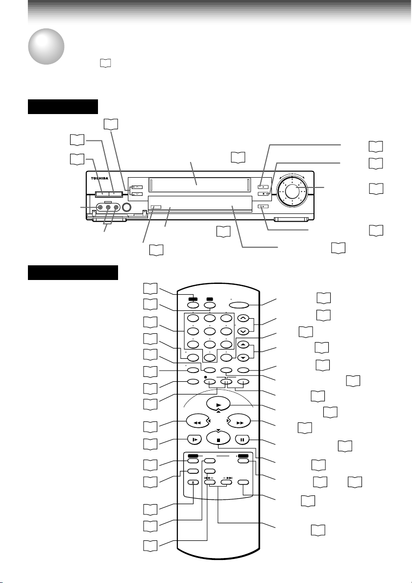
Front Panel
CHANNEL
EJECT
POWER
LINE IN 2
VIDEO jack
LINE IN 2 AUDIO
(L/MONO, R) jacks
Remote Control
To operate this VCR.
To operate your TV.
REMAIN/COUNTER
8
20
15
Number buttons
(For W-708 only)
26
POWER
c EJECT
LINE IN 2
VIDEO L-MONO-AUDIO-R
REC
VCR
TV
I.SELECT
DISPLAY
SP/SLP
REC
REW
SLOW
PROG.
VCR Plus+
EJECT
CANCEL
A.SELECT
Cassette compartment
CHANNEL
REC
Remote sensor
26
14
36
26
26
24
24
26
26
*
21
22
15
32
20
29
34
20
10
23
100
0
REMAIN/
COUNT RESET
COUNTER
REC
PLAY/x2
CURSOR
STOP
CANCEL
A.SELECTVCR Plus
65
9
19
POWER
CH/TRK
TV VOL
TV/VCR
TIMER
FFREW
PAUSE/STILL
µ
/
VCR TV
1
4
78
I.SELECT
DISPLAY
SP/SLP
SLOW
PROG. ENTER
+
EJECT INDEX
REV
FWD
(
)
PAUSE/STILL
PLAY
STOP
PAUSE/STILL
VCR display
POWER
CH/TRK
100
TV VOL
TV/VCR
15
26
18
36
26
COUNT RESET
TIMER
PLAY/x2
FF
28
*
*
21
PAUSE/STILL
*
STOP
DNR
ENTER
DNR
21
16
21
(For W-708 only)
INDEX
* These buttons are used to control the
cursor on the screen.
25
PLAY
STOP
SHUTTLE
9
24
21
22
19
µ
21
21
21
23
22
Page 12

VCR Display
INTRODUCTION
VCR indicator
Cassette indicator
POWER indicator
POWER
SLP
REC
REC (Recording)
indicator
Tape speed indicator
(SP/SLP)
Rear Panel
To wall outlet
VCR
TIMER
Timer recording indicator
REMAIN indicator
REMAIN
OFF indicator
PM
AM
OFF
DT
CH
Channel indicator
Tape running direction/speed indicator
LINE OUT VIDEO jack
LINE IN 1 VIDEO jack
HM
Multifunctional indicator
DT (Digital Auto Tracking) indicator
RF IN (FROM ANT.) terminal
L
Hi-Fi (L/R) indicators
R
L: Left channel
R:Right channel
S
off: Normal track
LINE IN 1 AUDIO jacks (L, R)
CH selector (3/4)
LINE OUT AUDIO jacks (L, R)
LINE IN 1 AUDIO (Rear), 2 (Front) jacks
If the connected equipment is monaural (has one audio output jack), connect the L (MONO) side, the same
sound is recorded on both L and R on the Hi-Fi track.
RF OUT (TO TV) terminal
9
Page 13
PREPARATION
How to Use the Remote Control
This section explains how to get ready for remote control operation.
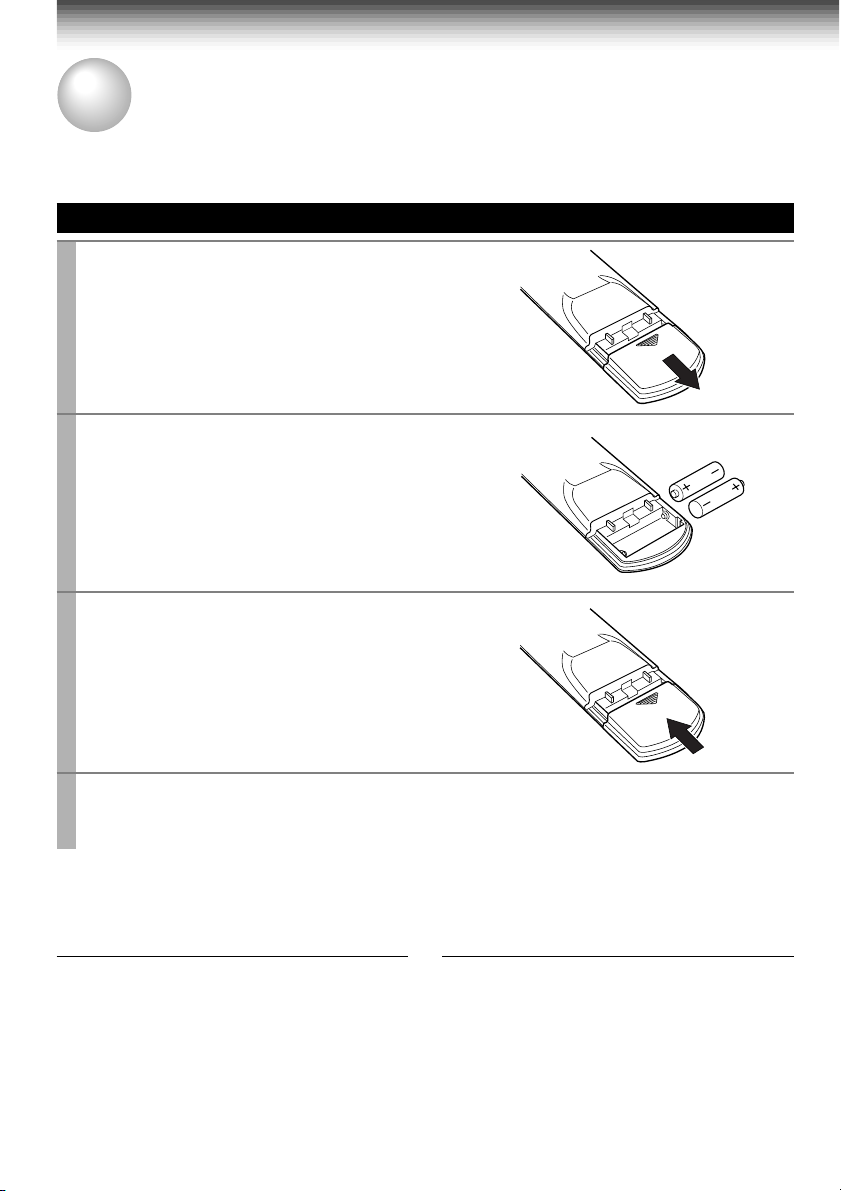
Setting up the Remote Control
Open the battery compartment lid on the
1
rear panel.
Install 2 batteries (“AAA” size) following
2
the polarity diagrams.
Close the battery compartment lid.
3
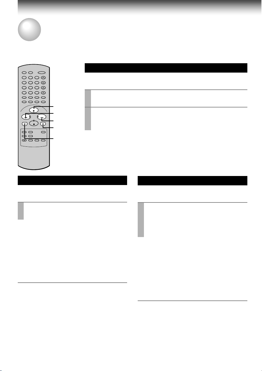
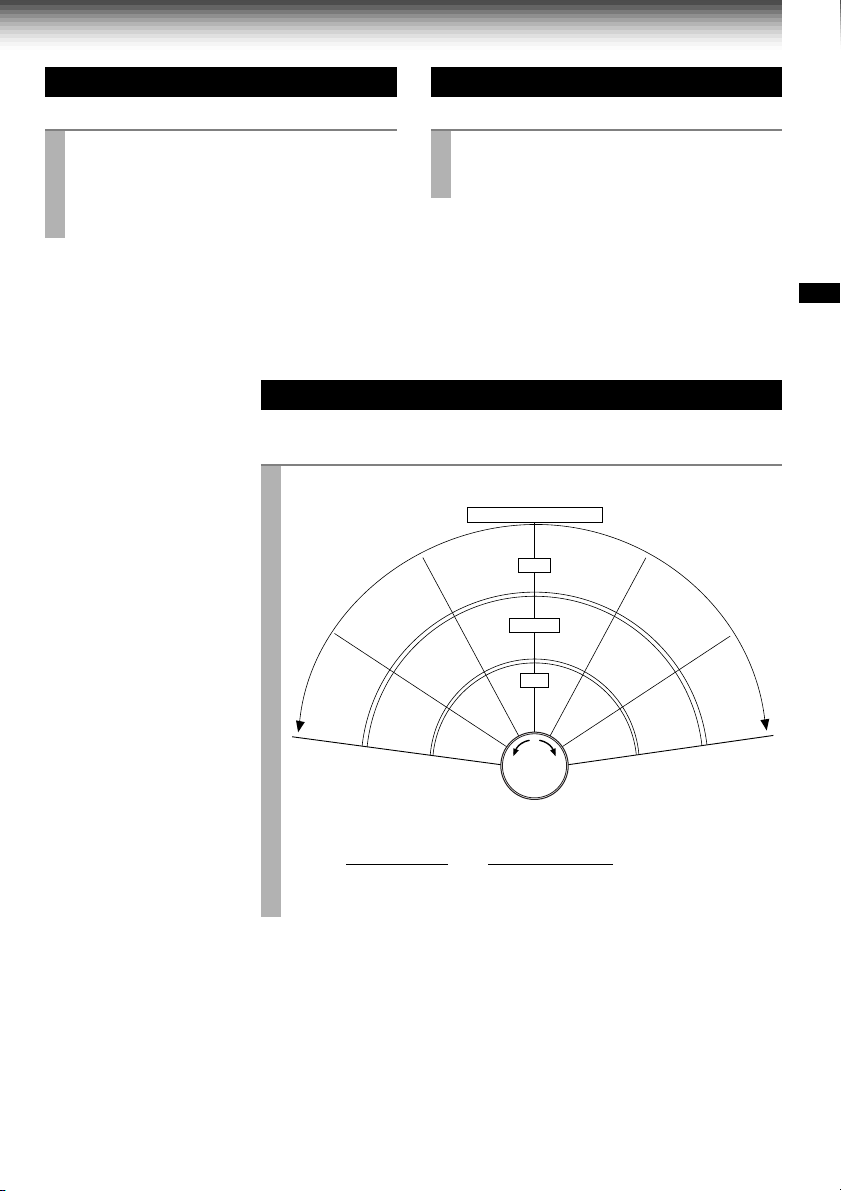
Point the remote control at the VCR and press the buttons within the operating range.
4
Distance: within about 7 m from the front of the remote sensor
Angles: within about 30˚ in every direction
Notes on batteries
• The life of the batteries is about 1 year
depending on the conditions of use.
• If the remote control does not operate correctly,
replace all batteries with new ones.
• If the remote control is not to be used for a
long period of time, remove the batteries to
avoid possible damage from battery corrosion.
10
Caring for the remote control
• Do not expose the remote sensor of the VCR
to a strong light source such as direct sunlight
or illumination (especially high-frequency
lighting) when using the remote control.
• Be careful not to spill water on the remote
control or to place it on anything wet, and avoid
sharp impacts.
Page 14
PREPARATION
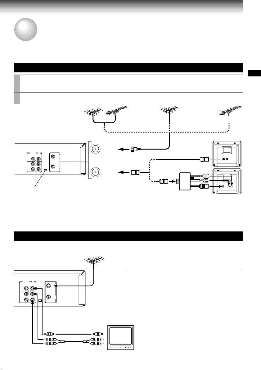
Connections
Before you use this VCR, it is necessary to connect it to your TV. Several ways of connecting are
available depending on your use of TV or cable box. Select one which is applicable to your equipment.
Antenna/VCR/TV Connection
Disconnect the antenna cable from your TV and connect it to the RF IN terminal on the
1
VCR.
Connect the RF OUT terminal to the TV.
2
PREPARATION
VHF/UHF combinaion
antenna
IN
(FROM ANT.)
OUT
(TO TV)
Setting the VCR Output Channel
When the VCR is connected in this way, the VCR sends the output
signals to channel 3 or 4 on your TV. Set the output channel
selector (CH selector) of the VCR to “3” or “4”, whichever is vacant
in your area.
VHF antenna
only
1
2
AUDIO/VIDEO Connections
The AUDIO/VIDEO jacks are also available to connect your TV.
When connected your TV using the
AUDIO/VIDEO OUT jacks
To watch video pictures, set the video input mode on
your TV. For the video input mode, refer to the
manual of your TV.
UHF antenna
only
Antenna splitter
(not supplied)
VHF/UHF
VHF UHF
LINE OUT VIDEO
VIDEO IN
AUDIO INLINE OUT AUDIO
11
Page 15

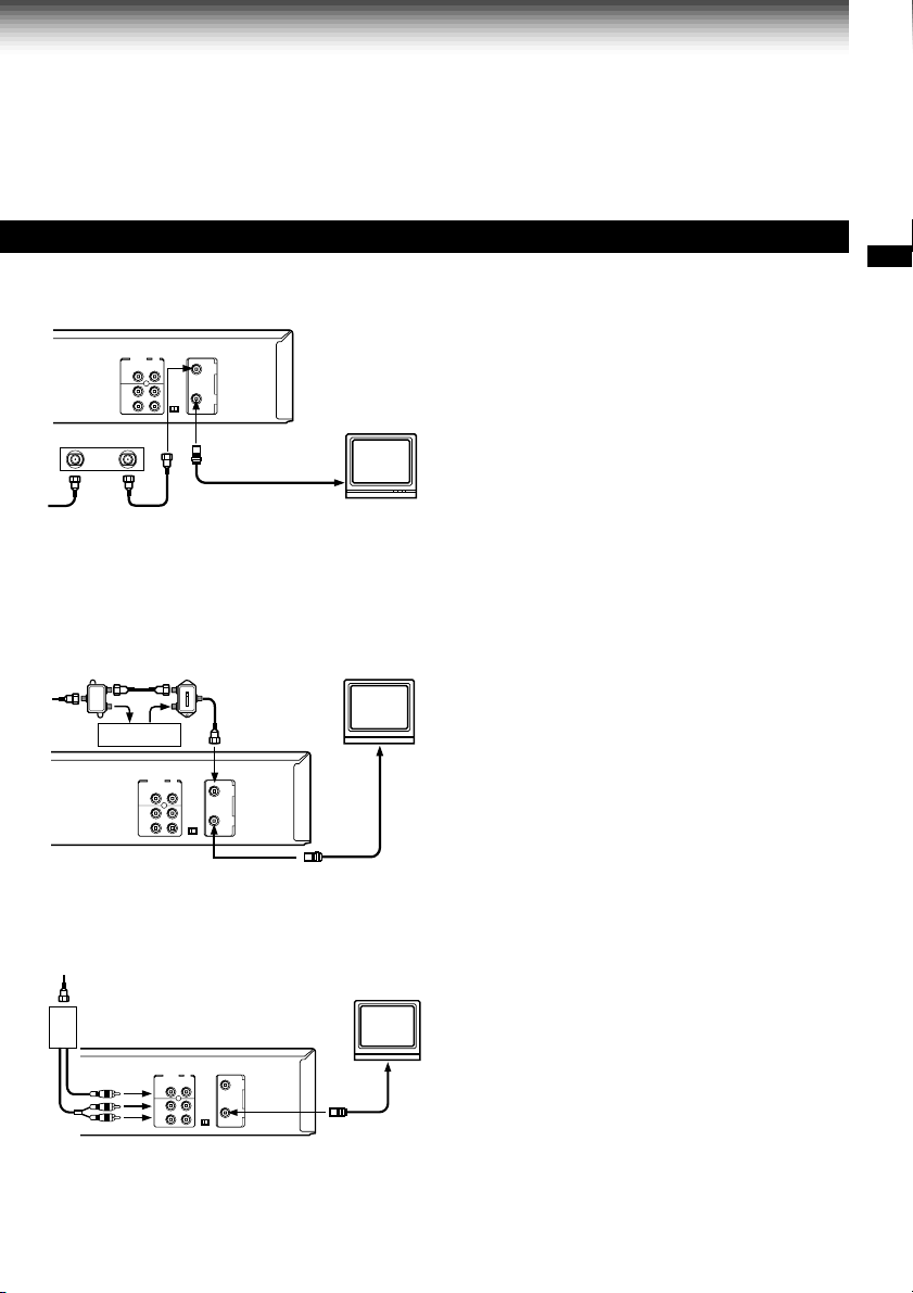
Connections (continued)
Cable Connection
Choose one of the below according to your usage of the cable box.
This set-up will enable you to:
– record an unscrambled channel.
– watch an unscrambled channel while recording
it.
– record an unscrambled channel while watching
another (only when you connect a cable-
Incoming cable
compatible TV).
You will need to:
• select TV channel 3 or 4 to receive video
signals. (See page 11.)
• to record a channel while watching another,
press
TV/VCR
the “VCR” indicator in the VCR display and
select a desired channel on the TV (only when
you connect a cable-compatible TV).
on the remote control to turn off
Incoming cable
12
Cable Box
IN OUT
This set-up will enable you to:
– record an unscrambled channel.
– watch an unscrambled channel while recording
it.
– record an unscrambled channel while watching
another (scrambled or unscrambled).
You will need to:
• set TV channel to the output channel of the
cable box.
• turn on the cable box and select cable channel
3 or 4 according to the output channel of the
VCR.
• to record a channel while watching another,
press
TV/VCR
the “VCR” indicator in the VCR display and
select a desired cable channel on the cable
box.
on the remote control to turn off
Page 16
Cable Box
Cable Box
PREPARATION
This set-up will enable you to:
– watch an unscrambled or scrambled channel
while recording it.
– record any channels through the cable box.
You will need to:
OUTIN
A/B switch
A
A
A
B
B
B
• set TV channel 3 or 4 to receive video signals.
(See page 11.)
• set VCR channel to the output channel of the
cable box, and select a desired cable channel
on the cable box.
• while the VCR is turned off or the “VCR”
indicator is not lit in the VCR display, set TV
channel to the output channel of the cable box.
This set-up will enable you to:
– watch an unscrambled or scrambled channel
while recording it.
– record an unscrambled channel while watching
another unscrambled channel (only when you
connect a cable-compatible TV).
• A/B switch “A”: record and watch an
unscrambled channel which
comes bypassing the cable box.
• A/B switch “B”: record and watch a scrambled
or unscrambled channel coming
through the cable box.
This set-up will enable you to:
Box
Cable
– watch or record a channel through the cable
box via the LINE IN 1 (AUDIO/VIDEO) jacks.
You will need to:
• press
I.SELECT
shows “L1”.
so that the VCR display
13
Page 17
PREPARATION
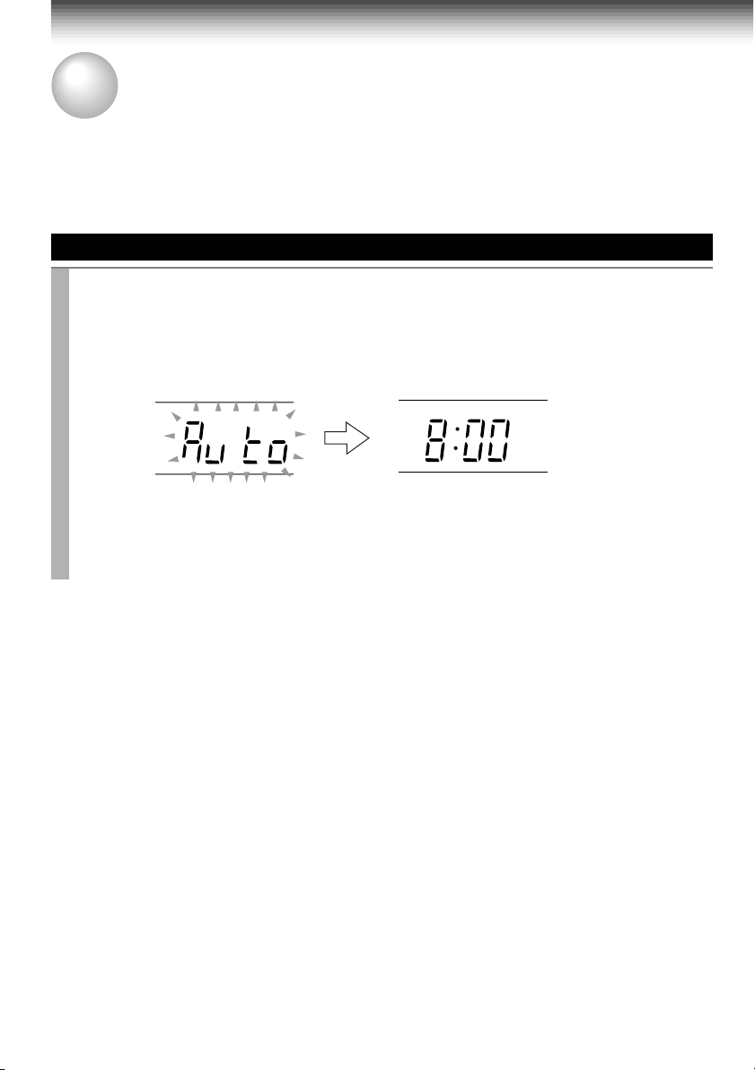
Auto Set Up
The Auto Set Up function automatically sets the tuner channels and clock when power is first connected
to the VCR.
Preparation
• Turn on the TV, and select the video channel (3 or 4), or the video input mode if you made the Audio/Video
connection (page 11).
• Press
I.SELECT
• Press
Auto Set Up
Connect the antenna cable to the VCR (see page 11). Then connect the VCR’s power
1
plug to an AC outlet.
“Auto” flashes in the VCR display as the VCR automatically tunes in all active stations.
When Auto Set Up is completed successfully, the current time will be displayed.
so that the channel number will appear if “L1” or “L2” is displayed in the VCR display.
VCR
to set the remote control operating the VCR.
VCR display
Tuning in progress.
VCR display
PM
Auto Set Up completed.
• If the VCR fails to set the clock, “– : – –” will be displayed. Set the clock manually. (Refer
to “Setting the clock” on page 16.)
Notes
• If you press the
• If Auto Set Up is not perform successfully, perform the clock and Tuner Channel procedures manually
(page 16 to 18).
• If, however, you want to add or delete channels, refer to “Adding or erasing channels” on page 18.
CANCEL
button, the Auto Set Up is cancelled.
14
Page 18

PREPARATION
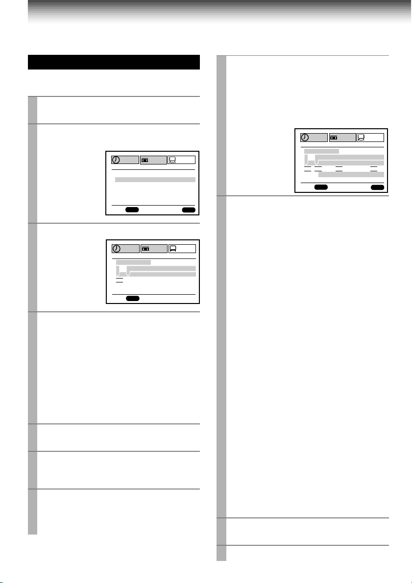
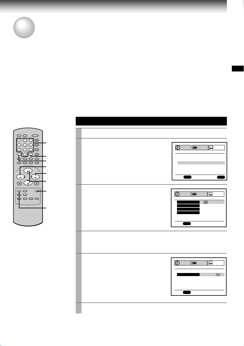
Initial Settings Using On-screen Display
Language selection must be set first when the VCR is first plugged in, or after it encounters a power
failure. You can also easily make necessary settings using the on-screen displays.
Preparation
• Turn on the TV, and select the video channel (3 or 4), or the video input mode if you made the Audio/Video
connection (page 11).
• Press
23
1
4
78
0
PLAY/x2
VCR
to set the remote control operating the VCR.
Setting the Language
VCR
POWER
65
9
100
REW
FF
FFREW
STOP
PLAY/x2,
STOP
ENTER
PROG.
Press
Press
POWER
PROG.
.
1
2
The following screen appears on the TV.
Select the language using
3
(
CURSOR
) or
) , and press
The screen turns to the MENU screen.
to turn on the VCR.
PLAY/x2
STOP (CURSOR
PROG.
.
n
ED:
PROGRAM
PROG
PROGRAM
SET UP
E
n
GLSIH
n
FRA
E
SPA
MEnU
SET UP
ÇA I
ñ
PRESET
S
OL
PRESET
PREPARATION
Press
PROG.
4
to return to the normal TV screen.
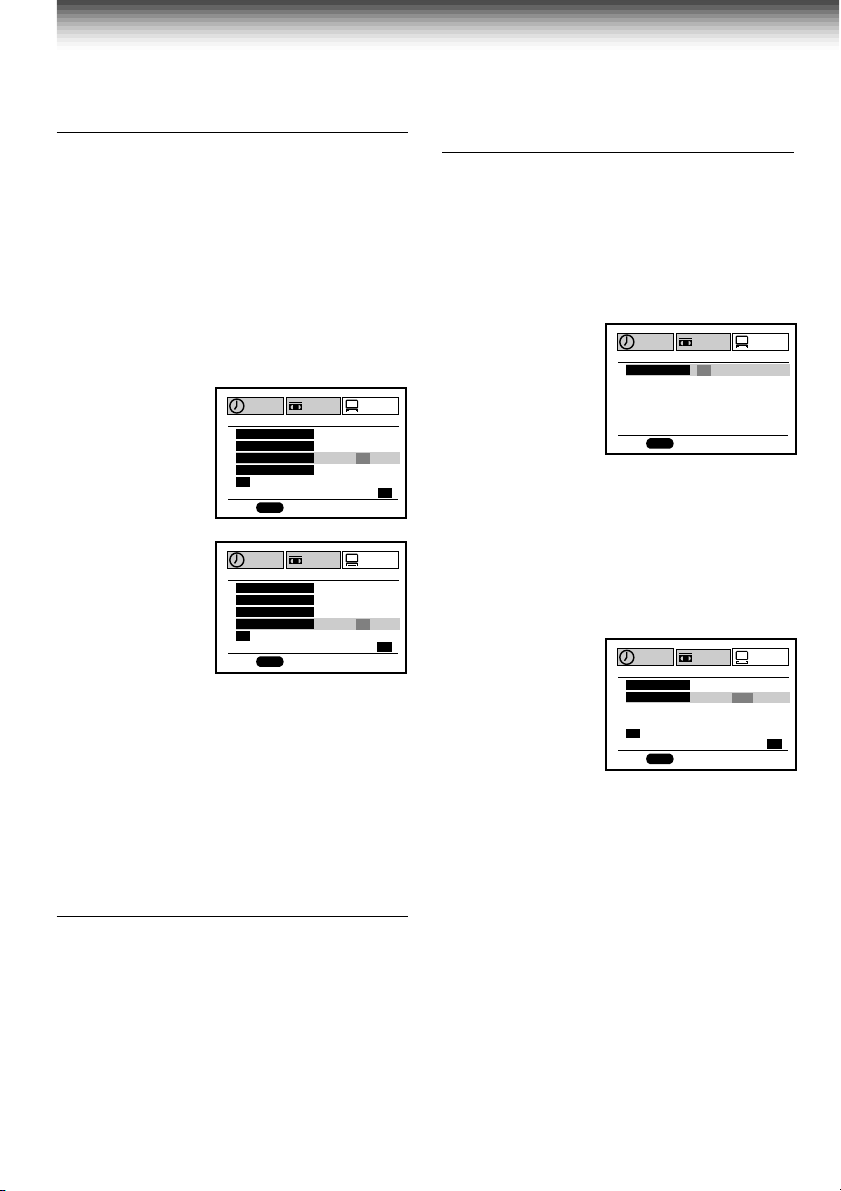
Optional settings on the SET UP screen
Other optional settings can be made. Press
ENTER
while “SET UP” is selected on the
MENU screen. The screen turns to the SET UP screen.
SET UP
PROGRAM
n
GUAG
nn
PROG
H
GT
n
E
TAPE LE
SAP SET
SIMULCAST
ANTE A
LA
X
DS InOF
n
ED:
To exit, press
PRESET
120 016 801
n
OFFO
n
OFFO
UATOUA
M
n
EG RFA SPE
n
OFFO
PROG.
Page 24
Page 34
Page 35
n
With “AUTO” set, a TV broadcast will appear via the TV tuner after
playback.
Move down here, and set to “AUTO” or “MANU”.
If you made the Audio/Video connection (page 11), set to “MANU”.
To change the language, move down here and set to the desired one.
With “ON” set, you can see the station ID and program title displayed on
TV.
n
ED:
PROG
ENTER
(Continued)
15
Page 19
Initial Settings Using On-Screen Display (continued)
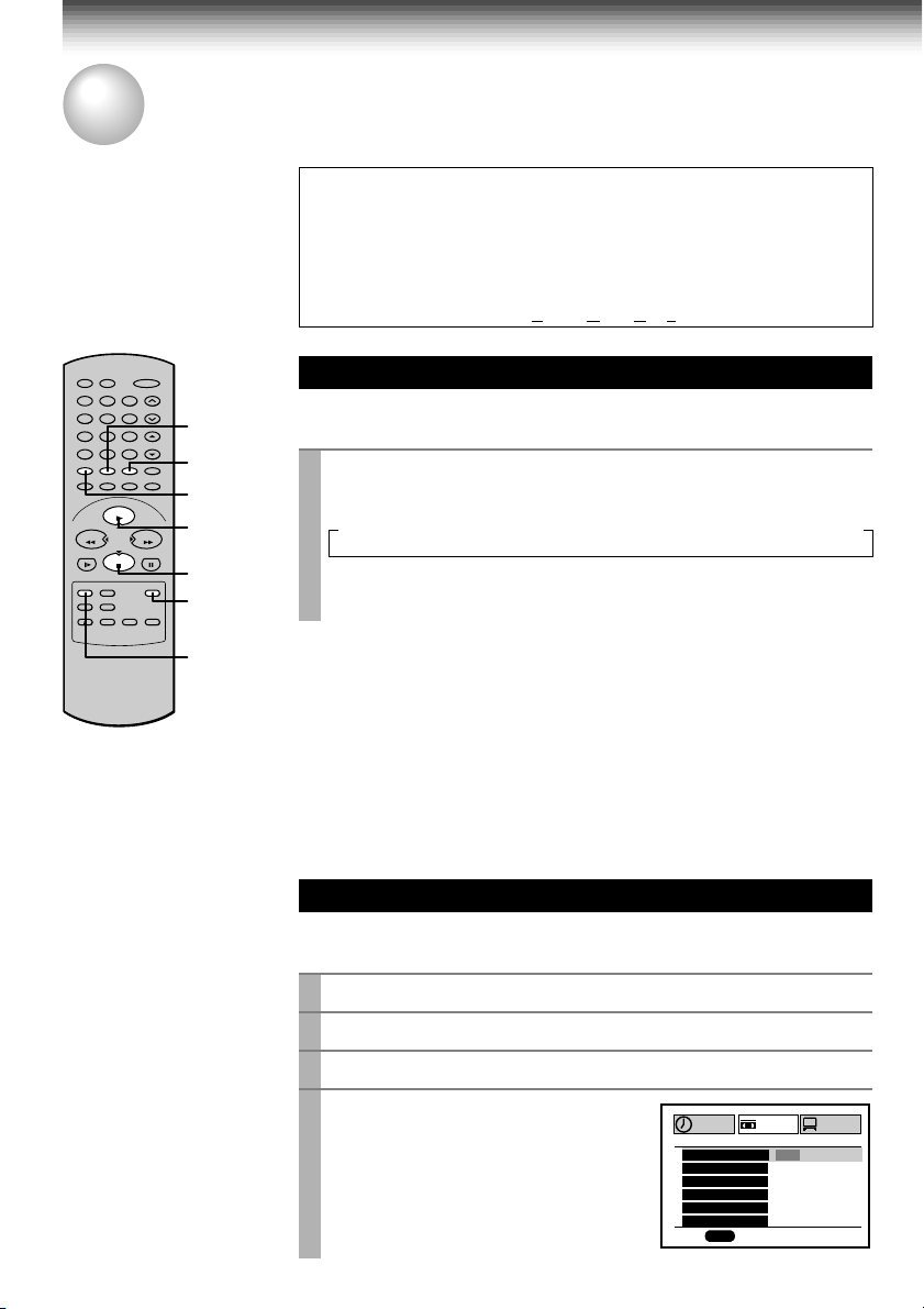
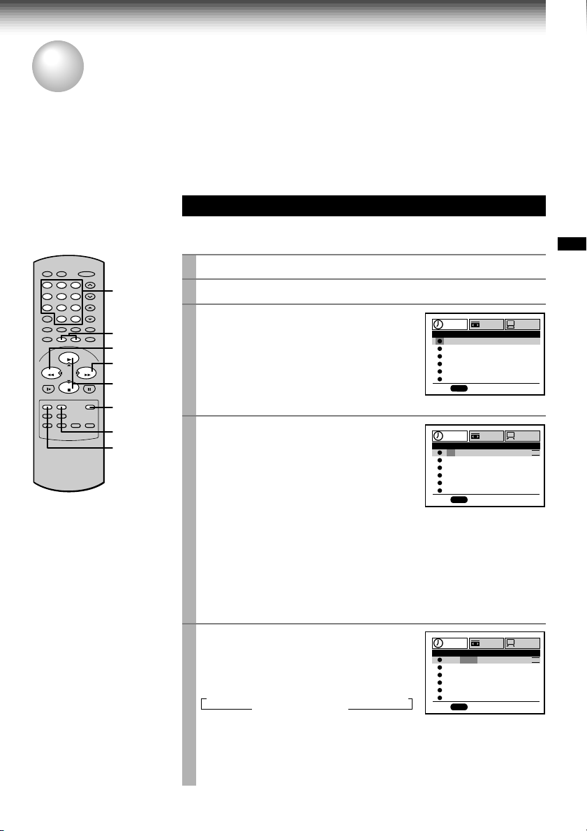
Setting the Clock
Example: To set the clock to 2:30 p.m. on
August 25 (summer time) 2000.
Press
PROG.
1
The MENU screen appears on the TV.
Select “PRESET” using FF or
2
press
ENTER
Note
“GUIDE CH” is for
W-708 only.
Press
3
Select “A UTO” or “MANU” using
4
x2
or
STOP
AUTO: The VCR automatically sets or
adjusts the clock.
If you select “AUTO” mode, proceed to step 8.
MANU: You can set the clock manually.
If you select “MANU” mode, select “SUMMER
TIME” using FF. Set to “IN” or “OUT” for the
summer (daylight saving) time using
or
STOP
the description in step 9.)
Move to the next using FF.
5
(To move back, press
Vary the digits to set the hour.
6
PLAY/x2
STOP
: To decrease.
Repeat steps 5 and 6 to set the minutes,
7
month, day, and the year (by the last two
digits).
Proceed to step 10 to start the clock.
.
REW
.
SET UP
PRESET
ET
RY
OX / D S S
SET UP
PRESET
AA
TED
E
A
M
ENTER
PROGRAM
CLOCK S
MEMO
CH
CABLE B
GU I DE HC
PROG
n
ED:
to select “CLOCK SET”.
PROGRAM
CL
O
CK S E T
SUMMEMERTI
TOU1000SA1’/
12 :
PROG
M
00
MANU
n
ED:
PLAY/
.
. (F or “IN” and “OUT” selections, see
REW
.)
: To increase.
PLAY/x2
, and
ENTER
RYETI
Press
8
ENTER
to start the “AUTO” clock
set feature.
After a while, the VCR automatically updates
the clock using the data broadcast by the
local TV stations.
The following screen will appear on TV
depending on the broadcast at your location.
O
CK S E T
SUMMEMERTI
n
I
M
57
:
9
PROG
PLAY/x2
SET UP
M
E
EAS
AR
E
A
10 00SA1’/
M
REW
PROGRAM
CL
AUTO AUTO AUTO AUTO
n
ED:
Select the options using FF or
9
Change the data using
STOP
.
1) Set “SUMMER TIME (DaylightSaving Time)”.
IN, daylight-saving time begins on the first
Sunday in April. Because the clock
automatically changes from 2:00 AM to
3:00 AM (forward one hour), remember
that any part of a scheduled Timer
Recording that falls between these two
times will not be recorded.
OUT, daylight-saving time ends on the last
Sunday in October. The VCR clock
automatically changes from 2:00 AM to
1:00 AM (back one hour). Therefore, it can
affect your recording length if one is set
for this time.
2) Set “Time Zone”.
If you select “AUTO” for your time zone,
the VCR sets the clock using the first
Coordinated Universal Time information it
finds. If the time is not correct, select
another time zone or use the “MANU”
option.
3) Set “CH”.
If you don't know the clock data channel,
select “AUTO”. The VCR will scan
automatically to tune the channel carrying
the clock data.
If AUTO CLOCK SET is unsuccessful, set the
time and date through the “MANU” clock set
menu selection.
Press
PROG.
10
Now the clock starts.
.
PRESET
OH
n
EZ
CTI
TER
n
TED
AEYTI
ENTER
.
or
2
16
11
Press
PROG.
to exit.
Page 20
PREPARATION
Storing Channels on the VCR
This section is required if you receive only normal TV or unscrambled cable channels, or use a cable box
between your TV and the VCR.
Incoming Antenna/Cable (CATV) Signals
The VCR scans through all receivable TV and CATV channels and stores only the active
ones in your area into the memory. Once the storing is finished, you can select a desired
channel using
Preparation
• Turn on the TV, and select the video channel (3 or 4), or the video input mode if you made the Audio/Video
connection (page 11).
• Press
I.SELECT
23
1
4
78
0
PLAY/x2
STOP
CH/TRK
.
so that the channel number will appear if “L1” or “L2” is displayed in the VCR display.
Incoming Antenna/Cable (CATV) Signals
Press
PROG.
1
Number
65
buttons
9
100
FFREW
100
I.SELECT
REW
FF
PLAY/x2,
STOP
ENTER
Select “PRESET” using FF or
2
and press
Note
“GUIDE CH” is for W-708 only.
Select “CH MEMORY” using
3
x2
or
STOP
1, 6
to display the MENU screen.
REW
ENTER
.
PLA Y/
, and press
ENTER
.
,
PROGRAM
CLOCK S
CH
CABLE B
GU I DE HC
PROG
n
ED:
PROGRAM
TV / C TAV
AUTO SCA
ADD CH
ERAS CEH
n
SET UP
MEMO
SET UP
ET
RY
OX / D S S
PRESET
TV TVAC
––
––
PRESET
OFFO
CH
CH
PREPARATION
ENTER
n
n
ED:
Set “TV/CATV“ to “TV” or “CATV” using FF or
4
TV: To store channels received via the antenna.
CATV: To store channels received via the incoming cable.
Select “AUTO SCAN” using
5
or
STOP
, and press FF to set to
“ON”.
The VCR starts scanning and the
PLA Y/x2
PROGRAM
AUTO SCA
channels are stored in the VCR in
ascending order. When the scanning is
finished, the screen automatically
n
ED:
returns.
Press
PROG.
6
to exit.
PROG
PROG
REW
TV
n
.
SET UP
PRESET
OCH2
n
17
Page 21
Storing Channels on the VCR (continued)
Adding or erasing channels
Adding channels
If a desired channel cannot be scanned
automatically because of a weak signal, it can be
added to the memory.
Erasing channels
You can erase a stored channel from the memory
if it is unnecessary.
1)Follow steps 1 to 3 of “Incoming Antenna/CATV
Signals”.
2)Select “ADD CH” or “ERASE CH” using
or
STOP
.
To add channels
To erase channels
PROGRAM
TV / C TAV
AUTO SCA
ADD CH
ERAS CEH
OSETCH
T
PROG
n
ED:
PROGRAM
TV / C TAV
AUTO SCA
ADD CH
ERAS CEH
OSETCH
T
PROG
n
ED:
PUSH ~90EYSK
PUSH ~90EYSK
3)Enter a channel number of 1 to 125 using
number buttons
.
For more than 100 number, first press
For CATV channels, refer to the chart below.
(For other orders, check with your cable
company.)
4)Repeat steps 2) and 3) to add or erase
channels as necessary.
5)Press
PROG.
to exit.
n
n
SET UP
SET UP
PLAY/X2
PRESET
TV
FFO
––
––
PRESET
TV
FFO
––
––
100
TVAC
n
O
n
O
n
O
TVAC
n
O
n
O
n
O
.
Cable Box/DSS Output Channel
Setting
To set the Cable Box/DSS output Channel on the
VCR.
1)Press
2)Select “PRESET” using FF or
3)Select “CABLE BOX/DSS” using
4)Select “NO”, “C.BO X” or “DSS” using FF or
5)If set to “C.BOX” or “DSS”, select “OUTPUT CH”
6)Press
PROG.
to display the MENU screen.
REW
ENTER
STOP
.
, and press
ENTER
ED:
USE
n
.
PROGRAM
PROG
, and press
PLAY/X2
SET UP
C.BOXO
n
or
PRESET
SSD
REW
according to your connection type.
using
PLAY/X2
or
STOP
. Then enter the output
channel number of your cable box (Usually 3 or
4, check the rear of the cable box.) or line input
mode “L1” using the
I.SELECT
button according
to your connection.
SET UP
n
O
C.BOX
PRESET
3
SSD
HC
PROG.
to exit.
USE
OUT UT CHP
n
ED:
PROGRAM
OSETCH
T
PUSH ~90EYSK
PROG
Selecting stored channels
Once the active channels have been stored, you
can select the channels in two ways below.
Number buttons
To enter digits of the channel number.
• For one-digit number, enter 0 before.
• For more than 100 number, first press
• Each
number button
needs to be pressed
within 2 seconds.
CH/TRK
To shift up or down the stored channel numbers.
18
100
.
Page 22

Channel reference chart
Number on the VCR
Corresponding channel number
10 11 12 13 14 15 16 17 18 19 20 21 22 23 24 25 26 27 28 29 30
10 11 12 13 14 15 16 17 18 19 20 21 22 23 24 25 26 27 28 29 30
10 11 12 13 A B C D E F G H I J K L M N O P Q
31 32 33 34 35 36 37 38 39 40 41 42 43 44 45 46 47 48 49 50 51
31 32 33 34 35 36 37 38 39 40 41 42 43 44 45 46 47 48 49 50 51
R S T U V W AA BB CC DD EE FF GG HH II JJ KK LL MM NN OO
52 53 54 55 56 57 58 59 60 61 62 63 64 65 66 67 68 69 70 71
52 53 54 55 56 57 58 59 60 61 62 63 64 65 66 67 68 69 – –
PP QQ RR SS TT UU VV WW XX YY ZZ AAA BBB 65 66 67 68 69 70 71
93 94 95 96 97 98 99 100 101 102 103
–––––––––––…–––––
93 94 A-5 A-4 A-3 A-2 A-1 100 101 102 103
TV
CATV STD (HRC/IRC)
123456789
–23456789
1(A-8)
234
…
121 122 123 124 125
…
121 122 123 124 125
5(A-7) 6(A-6)
7
CATV signals
• STD (standard) cable TV signals
• HRC (Harmonic Related Carriers) cable TV signals
• IRC (Incremental Related Carriers) cable TV signals
IRC is also called ICC (Incremental Coherent Carriers)
89
…
…
…
PREPARATION
19
Page 23
PREPARATION
Video Cassette Use
Video Cassette Use
Loading a cassette
Push the cassette into the cassette compartment with the window side facing up and the
label side towards the front. The VCR is automatically turned on. The indicator will
appear in the VCR display.
Ejecting a cassette
Press
EJECT
. The cassette is ejected from the cassette compartment.
Warning
Do not insert your hands or any foreign objects into the compartment. This may result
in injury or damage. Take special care with children to avoid accidents.
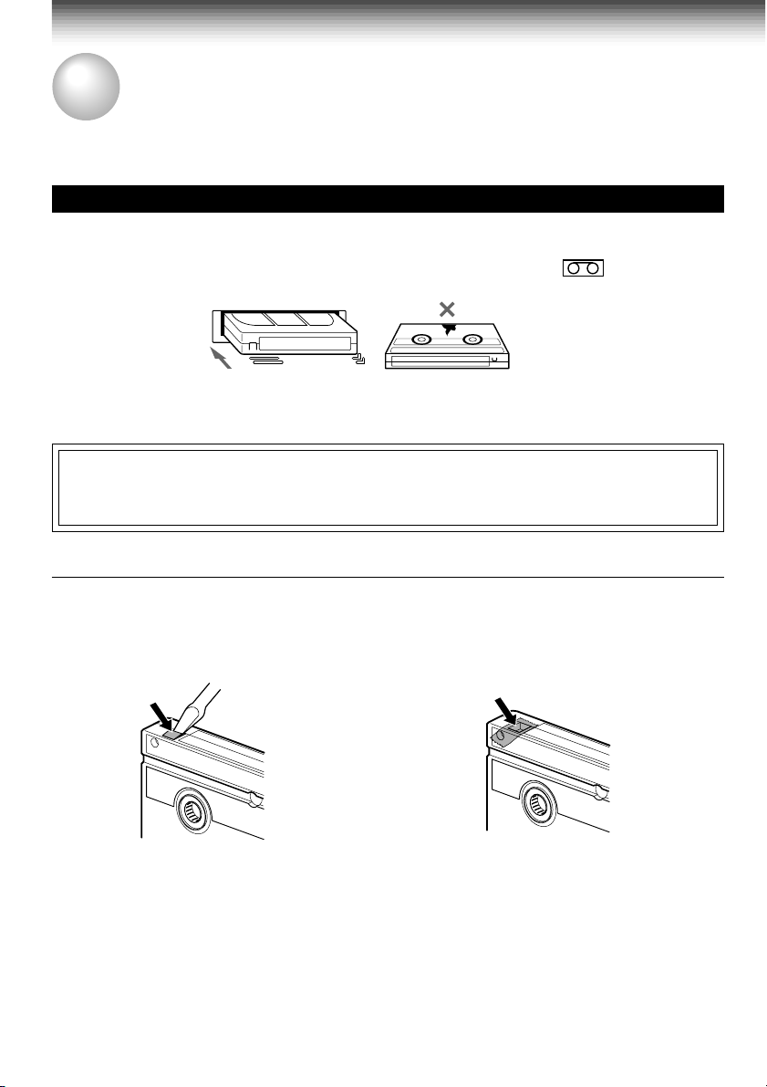
Precautions when using video cassettes
Video cassettes have a safety tab to prevent accidental erasure. If the tab has already been removed,
recording cannot be performed.
To prevent accidental erasure
Remove this safety tab with a screwdriver.
• Avoid exposing cassettes to direct sunlight. Keep them away from heaters.
Avoid extreme humidity, vibrations or shock, strong magnetic fields (near a motor, transformer or
magnet) and dusty place.
20
To record again
Cover the tab hole with adhesive tape.
Page 24
PLAYBACK
K
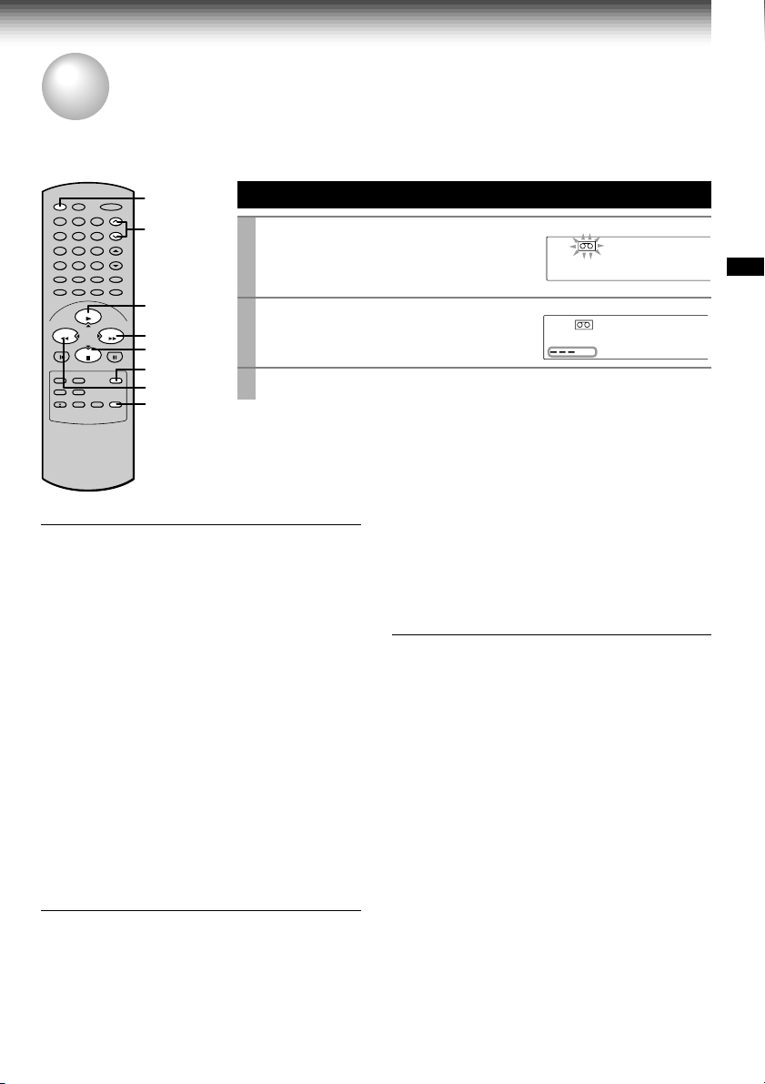
Playback
This section explains the basic playback operation.
Preparation
• Select the video channel (3 or 4) or video input mode on the TV.
• Press
VCR
to set the remote control operating the VCR.
Basic Playback
Load a recorded cassette.
1
Pow er is turned on.
If the cassette has no safety tab,
playback starts automatically.
Press
2
3
PLAY/x2
T o stop pla yback, press
Rewinding / Fast-forwarding
Press
REW
to start playback.
or FF in the stop mode.
23
1
4
78
0
PLAY/x2
STOP
VCR
CH/TR
65
9
100
2
FFREW
FF
3
µ
19
REW
DNR
STOP
POWER
PLAYBACK
POWER
SP
VCR
DT
.
Adjusting the tracking
When playback starts, the VCR automatically
adjusts the tracking for clear pictures and sound
(Digital Auto Tracking).
The “DT” indicator blinks during the adjusting.
If the VCR cannot locate the best possible
tracking point, hold down one of
CH/TRK
to
adjust the tracking manually.
• To resume the digital auto tracking, hold down
both
CHANNEL
on the VCR simultaneously for
about 2 seconds.
Notes
• During the adjusting, the playback picture and
sound may be distorted.
• The digital auto tracking is activated only in the
playback mode.
• To reset the manual tracking point to the center,
press both
simultaneously for not longer than 1 second.
• The noise on the screen may not be completely
CHANNEL
on the VCR
eliminated depending on the tape used,
especially when the tape was recorded on
another VCR.
19µ HEAD
You can view high quality pictures while playing
back a tape recorded in the SLP tape speed.
By pressing 19µ repeatedly, the 19µ HEAD mode
is displayed on the TV screen as follows:
19U HEAD AUTO: Usually set to “AUTO”. As the
playback starts, the VCR automatically activates
the 19µ head and reproduces high quality pictures .
19U HEAD OFF: Set to “OFF” if the pictures are
marred by dots.
Note
During playback with the 19µ head, momentary
noises or shakes may be produced when you
change the mode to the picture search or
variable speed playback.
DNR (Digital Noise Reduction)
(For W-708 only)
The noise reduction function of this VCR is based
on a digital signal system utilizing memory, and is
effective in the playback of noisy tapes.
Furthermore the CSE (Color Signal
Enhancement) circuit, which is included in the
system, compensates for color signal weakness
and gives the best possible color. Thanks to this
circuit color distortion is reduced and a sharp
picture is played back.
Press
DNR
DnR On: Usually set to “On”.
DnR OFF: This function will not work.
Notes
• The DNR playback is available only in the
playback mode.
• Depending on the recorded picture, for example
too vivid or too noisy, you may not notice a
reduction in the noise.
• The noise reduction may not work on pictures
recorded from special equipment such as TV
game machines or computers.
repeatedly to select the following:
The “DnR On” will appear on the TV
screen and you can view the picture
with less noise.
21
Page 25
PLAYBACK
Variable Speed Playback
You can play back a tape at various tape speeds.
Picture Search
23
1
4
78
0
PLAY/x2
STOP
65
9
100
PLAY/x2
REW
FFREW
FF
PAUSE/STILL
SLOW
A tape runs at 5 times or 7 times the normal playback speed so
that you can quickly locate a particular scene.
Press FF or
1
The tape runs at 5 times the normal playback speed.
To change the tape speed to 7 times the normal playback
2
REW
speed, press and hold
If you release it, the tape speed returns to 5 times.
Note
If you press FF or
forwarding or rewinding.
REW
during picture search, the mode changes to fast-
To resume normal playback
Press
PLAY/x2
.
during playback.
FF
or
REW
.
Still Picture
A picture freezes so that you can watch
closer.
Press
1
PAUSE/STILL
The picture freezes.
To resume normal playback
PAUSE/STILL
Press
Notes
• The still mode is automatically cancelled after
about 5 minutes and returns to normal playback.
• The still picture may shake if a picture of a fastmoving object or scene is frozen. This is not a
defect in the unit.
Adjusting Still Picture Stability
If the still picture is distorted or flickers, hold
down one of
stable.
Note
The distortion of the still picture may not be
eliminated completely.
Note
When playing back a tape which is recorded in S-VHS format, distortion may occur during the variable speed
playback.
CH/TRK
during playback.
.
until the picture becomes
Slow-motion Picture
The tape runs at 1/7th or 1/15th the normal
playback speed.
Press
SLOW
1
The tape runs at about 1/7th the normal
playback speed.
Each time you press
alternates between 1/7th and 1/15th.
To resume normal playback
PLAY/x2
Press
Notes
• The slow-motion picture mode is automatically
cancelled after about 5 minutes and returns to
normal playback.
• The slow-motion picture may flicker up and down.
This is not a defect in the unit.
Adjusting the Tracking Manually
If the slow-motion picture is noisy, hold down one
of
CH/TRK
Note
The noise in the slow-motion picture may not be
eliminated completely.
during playback.
SLOW
, the speed
.
until the best picture is obtained.
22
Page 26
Frame Advance
A picture advances frame by frame.
Press
1
PLAY/x2
Each time you press
during still playback.
PLAY/x2
, the picture
advances one frame.
If you press and hold
PLAY/x2
, the tape runs
at 1/30th the normal playback speed.
To resume normal playback
Press
PAUSE/STILL
.
Shuttle Dial Operation
You can also activate the picture search and slow playback at
various speeds by turning the shuttle dial on the VCR.
Double Speed Playback
A tape runs at twice the normal speed.
Press
1
PLAY/x2
The picture runs at twice the normal playback
speed.
To resume normal playback
PLAY/x2
Press
during playback.
.
PLAYBACK
1
Turn the
shuttle dial
i
t
c
e
r
i
d
k
c
a
b
y
a
l
P
Rewinding
R
:
n
o
Rewinding
e
v
e
Picture
search
on the VCR.
Initial mode of tape operation
Picture
search
–x7
–x5
Reverse
playback
Rewinding
Reverse
playback
Reverse
playback
–x1
–x1
playback
–x1
Stop
Playback
Reverse
–x1
P
l
a
y
b
a
c
k
Fast-
Picture
Search
forwarding
d
i
r
e
c
t
Fast-
forwarding
i
o
n
:
F
o
r
w
a
r
d
Fast-
forwarding
Double
speed
playback
x2
Picture
Still
Slow
1/15
x
1/7
x
search
x5
Slow
x7
Normal
playback
x1
e
s
r
The playback speeds differ depending on the recording tape speed of
the tape as follows.
Picture search Reverse playback
SP: x5 x7 -x1
SLP: x15 x21 -x3
Notes
• The still picture mode will be released automatically after about 5 minutes
and forward playback will start.
• Fast-forwarding or rewinding started from the stop mode continues even if
the
shuttle dial
is released. To stop, press
STOP
.
• The reverse playback mode will be released automatically after about 25
seconds and forward playback will start.
• Noise bar may appear in reverse playback.
Note
If you playback a tape recorded in the SLP tape speed or a tape recorded on another VCR in various speed
mode, the picture may be noisy or monochrome.
23
Page 27
PLAYBACK
Useful Functions in Tape Operation
These functions will help your playback.
S-VHS Quasi Playback (SQPB)
• This VCR can also play back a tape which is recorded in S-VHS format.
But the playback picture does not have the same quality and resolution as
the original S-VHS playback picture.
• This VCR cannot record in S-VHS format.
* SQPB is an abbreviation for S-VHS Quasi Playback.
Counter Function
23
1
4
78
0
PLAY/x2
65
REMAIN/
9
FFREW
COUNTER
COUNT RESET
DISPLAY
PLAY/x2
STOP
ENTER
100
STOP
You can view the clock, linear time counter or tape remaining
time in the VCR display or on the TV screen.
Each time you press
1
REMAIN/COUNTER
changes in sequence as follows:
→ Linear time counter (HMS) → Tape remaining time (REMAIN/RT) → Clock
The indication above will also appear on the TV screen by pressing
DISPLAY
. The y are s witchable with
REMAIN/COUNTER
, the VCR display
.
24
PROG.
To reset the linear time counter to “0H00M00S”
The counter is automatically reset to “0H00M00S” when a cassette is
ejected. If you want to reset at another point, such as the beginning of a
new recording, just press
COUNT RESET
.
Notes
• The linear time counter does not work on non-recorded portions on the tape.
• When the tape is ejected or the VCR is turned off, the display changes to
clock.
• If the tape rewinds back over “0H00M00S”, “–” appears in the VCR display.
• The displayed time of the linear time counter is only an approximation.
Tape Remaining Time
To view the tape remaining time in the VCR display, select the
tape length beforehand.
Turn on the VCR and load a cassette.
1
Press
PROG.
2
Select “SET UP” using FF or
3
Select the length of the tape.
4
T120: for a T-120 tape or shorter
T160: for a T-140 or T-160 tape
T180: for a T-180 tape
to display the MENU screen.
REW
, and press
TAPE LE
SAP SET
SIMULCAST
ANTE A
LA
X
n
ED:
PROGRAM
nn
n
GUAG
DS InOF
PROG
ENTER
SET UP
H
GT
n
120 016 801
OFFO
OFFO
UAT
E
n
EG RFA SPE
OFFO
.
PRESET
n
n
O
M
n
n
UA
Page 28
Press
PROG.
5
6
Press
to exit.
REMAIN/COUNTER
.
The remaining time (“RT - : - -”) appears in the VCR display.
Notes
• The displayed remaining time is an approximation.
• The remaining time is calculated according to the tape speed (SP or SLP)
and the cassette type.
23
1
4
78
0
PLAY/x2
Index Search Function
65
9
100
3
FFREW
STOP
2
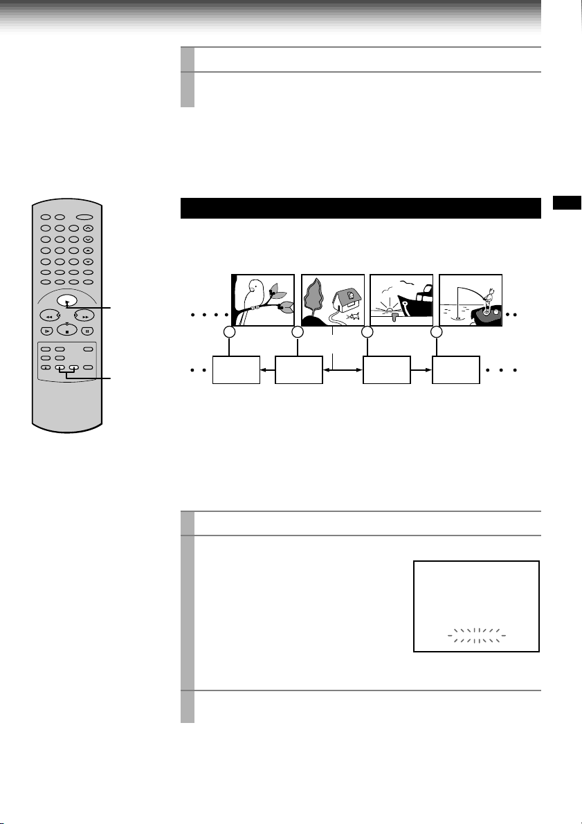
The VCR can find a point where a registered index signal is on a
tape and play back for about 5 seconds. You can easily locate
the desired program by inputting the index signal.
2 1 1 2
Playback
for 5 sec.
Index search
Playback
for 5 sec.
Playback
for 5 sec.
Playback
for 5 sec.
PLAYBACK
Registering index signals
Each time a recording starts, an index signal is automatically registered.
To register it somewhere else, press
Note
A certain interval is required between the index signals: more than 1 minute in
the SP tape speed and more than 3 minutes in the SLP tape speed.
INDEX
f during recording.
Index search
Load a cassette with the index signals registered.
1
Press
INDEX
2
g INDEX:To search in the reverse
INDEX f:To search in the forward
The VCR fast-forwards or rewinds the
tape. When an index signal is found, the
VCR plays back the tape for about 5
seconds, and then resumes fastforwarding or rewinding. This is repeated
each time at an index signal.
in the stop or playback mode.
direction.
direction.
00000
HMS
INDEX MARK
Press
3
PLAY/x2
when the desired program is found.
Normal playback starts.
Notes
• At the very beginning of the tape, the index search may not work properly.
• If you registered the index signals on a tape recorded on another VCR, the
recording may be blurred at the index point and the index search may not
work properly.
25
Page 29

RECORDING
T
Recording a TV Program
This section explains the basic recording operation.
Preparation
Select the video channel (3 or 4) or video input mode on the TV.
Basic Recording
Load a cassette with the safety tab attached.
to
1
Press
2
TV/VCR
indicator appears in the VCR displa y.
Select a channel to record with
3
CHANNEL
or
number buttons
control.
If you see “L1” or “L2” in the VCR display, press
channel number appears.
• If you record cable channels via the cable box, make the output
channel number of the cable box or “L1” appear, depending on your
connection. (See pages 11 – 13.)
Press
4
SP/SLP
recording tape speed.
SP: Suitable for general recording with
better picture and sound quality.
SLP: Suitable for tripling recording time, but with less picture and
sound quality than using the SP tape speed.
Press
5
REC
simultaneously press both
the remote control.
Recording starts.
so that the “VCR”
on the VCR, or
on the remote
to select the
on the VCR, or
23
1
4
65
78
0
100
3
9
2
PLAY/x2
STOP
5
4
FFREW
6
I.SELEC
To record from other
connected equipment
In step 3, press
switch the display as follows:
LI: To record via the LINE IN
1 jacks on the rear panel.
L2: To record via the LINE IN
2 jacks on the front panel.
I.SELECT
CH/TRK
REC
on
POWER
SLP
VCR
POWER
SLP
VCR
I.SELECT
POWER
SLP
VCR
POWER
SLP
VCR
REC
CH
so that the
CH
TIMERREC
CH
Press
6
Watching a TV program while
recording another
1) While recording, press
“VCR” indicator.
2) Choose another channel using the channel
selector on the TV.
TV/VCR
to turn off
Skipping unnecessary scenes while
recording
Press
PAUSE/STILL
to stop recording
momentarily. To resume recording, press
PAUSE/STILL
Note
The VCR automatically shifts to the stop mode if the
recording pause mode continues for 10 minutes.
again.
26
STOP
to stop recording.
Recording off time setting
By setting the recording off time, the recording
stops and the VCR is turned off automatically.
While recording, press
repeatedly to set the desired off time.
Each time you press
about 4 hours later and “- : - -” appear cyclically.
POWER
SLP
VCR
REC
Notes
• To cancel the recording in progress, press
• If the VCR clock is not set, this function will not
activate.
REC
on the VCR
REC
, each half-hour up to
PM
CH
OFF
STOP
.
Page 30
RECORDING
Timer Program Recording
The programmable timer allows you to record up to 6 different programs over one month.
Preparation
• Select the video channel (3 or 4) or video input mode on the TV.
• Make sure that the clock is set correctly (page 16).
• Store the channels on the VCR (pages 18 and 19).
• If you record cable channels via the cable box, keep the cable box turned on and select a channel to record
on the cable box.
Timer Programming Procedure
Example: To record cable channel 25 in the SP tape speed from
9:30 p.m. until 10:00 p.m. on August 30. Today is August 25.
Load a cassette with the safety tab attached.
23
1
4
78
0
PLAY/x2
65
4
9
100
10
REW
FF
FFREW
STOP
PLAY/x2,
STOP
ENTER
CANCEL
2, 9
1
Press
PROG.
2
Select “PROGRAM” using FF or
3
REW
, and press
Move to the next using FF, and enter
4
the channel number 25 by using
PLAY/x2, STOP
buttons
to display the MENU screen.
ENTER
or
.
number
.
SET UP
PROGRAM
O
CH DATE O DFF SP
–– – / –– –: –– –: ––
–– – / –– –: –– –: ––
–– – / –– –: –– –: ––
–– – / –– –: –– –: ––
–– – / –– –: –– –: ––
–– – / –– –: –– –: ––
n
ED:
PROGRAM
CH DATE O D
25
–– – / –– –: –– –: ––
–– – / –– –: –– –: ––
–– – / –– –: –– –: ––
–– – / –– –: –– –: ––
–– – / –– –: –– –: –
n
ED:
n
PROG
SET UP
O
n
– / –– –: –– – : –
PROG
PRESET
PRESET
FF SP
–
–
–
–
–
–
–
–
SLP
–
–
–
–
–
RECORDING
If you use the cable box, enter the output channel number of the
cable box with
I.SELECT
number buttons
or make “L1” appear by pressing
, depending on your connection. (See page 13.)
To make corrections:
Press
REW
to move back to the item, or FF to forward.
Move to the next using FF, and set
5
the recording date using
STOP
.
The date changes as follows:
→ 8/25 → 8/26 → … → 9/24 →
MO~FR ←
WKLY
PLAY/x2
WKLY
SA ←
SU →
or
…
n
ED:
SET UP
PROGRAM
O
CH DATE OFF DPS
25 8/30
–:–– –:––
–– – / –– –: –– –: ––
–– – / –– –: –– –: ––
–– – / –– –: –– –: ––
–– – / –– –: –– –: ––
–– – / –– –: –– –: ––
PROG
[WKLYSU]…[WKLYSA]: You can record TV programs on the same
channel on the day and time every week.
[MO~FR]: You can record TV programs on the same channel on the
day and time Monday through Friday.
PRESET
n
(Continued)
SLP
–
–
–
–
–
27
Page 31

Timer Program Recording (continued)
Move to the next using FF, and set
6
the hour and minutes of the
recording start time.
Move to the next, and set the
7
recording off time.
Move to the next, and select the tape
8
speed (SP) using
For the tape speed “AUTO (Auto Speed
Select)”, see below.
To set another program, press FF, and
select the next line pressing
Repeat steps 4 to 8.
Press
PROG.
9
Now programming is completed.
Press both
10
The power turns off and the VCR enters
the timer standby mode.
.
TIMER
PLAY/x2
or
STOP
STOP
.
simultaneously.
SET UP
PROGRAM
CH DATE OFF DPS
25 8/30:30
–– – / –– –: –– –: ––
–– – / –– –: –– –: ––
–– – / –– –: –– –: ––
–– – / –– –: –– –: ––
–– – / –– –: –– – : ––
PROG
n
ED:
PROGRAM
CH DATE OFF DPS
25 8/30 9:30
–– – / –– –: –– –: ––
–– – / –– –: –– –: ––
–– – / –– –: –– –: ––
–– – / –– –: –– –: ––
–– – / –– –: –– –: ––
PROG
n
ED:
.
PROGRAM
CH DATE OFF DPS
25 8/30 9:3010:00
–– – / –– –: –– –: ––
–– – / –– –: –– –: ––
–– – / –– –: –– –: ––
–– – / –– –: –– –: ––
–– – / –– –: –– –: ––
PROG
n
ED:
POWER
TIMER
O
9
SET UP
O
SET UP
O
PRESET
n
P
SLP
–:––
M
–
–
–
–
–
PRESET
n
P
P
SLP
:00
10
M
M
–
–
–
–
–
PRESET
n
P
P
SP
M
M
–
–
–
–
–
TIMERREC
Auto Speed Select
If you are not sure the tape is long enough for
timer program recording in the SP tape speed,
set the recording tape speed to “AUTO”.
Recording starts in the SP tape speed and the
VCR automatically selects the tape speed to
record the program to the end. If the tape length
is not long enough, the tape speed automatically
changes from SP to SLP.
28
Notes
• Make sure that the tape length is selected correctly
according to the tape used on the SET UP screen
(page 24).
• When the SLP tape speed is selected and the tape
length is not sufficient to record the program to the
end, the program cannot be recorded to the end.
• The picture will be distorted when playing the part
where the recording tape speed is switched from
SP to SLP with the Auto Speed Select feature.
Page 32

Confirming the timer programs
(in the timer standby mode)
Press
PROG.
.
The screen for confirming will appear.
SET UP
PROGRAM
CH DATE OFF DPS
25 8/30 9:3010:00
–– – / –– –: –– –: ––
–– – / –– –: –– –: ––
–– – / –– –: –– –: ––
–– – / –– –: –– –: ––
–– – / –– –: –– –: ––
PROG
n
ED:
After about 30 seconds, the screen disappears.
PRESET
O
n
P
M
If a power failure occurs during the
timer program recording (including
VCR Plus+
®
system recording (page
32))
• When a power failure has occurred, “- -:- -”
appears in the VCR display. Since the
P
SP
M
–
–
–
–
–
programmed contents have been cleared,
reset the clock and timer programming.
• When power has failed for a short time, the
colon of the current time display blinks. The
programmed contents are not affected. Reset
the clock.
Changing/cancelling the timer
programs
1) If the TIMER indicator is lit, press both
to turn it off, and then turn the VCR on by
pressing
POWER
.
2)With steps 2 to 9, change the items.
To cancel a program, select the program you
want to cancel in step 4, and press
The line is then cleared.
3)Press both
TIMER
to return to the timer
standby mode.
TIMER
CANCEL
Recording or playback in the timer
standby mode
First press both
standby mode, and then press
on the VCR. The VCR will be available for use.
• Be sure to press both
the VCR to the timer standby mode after you
are finished.
TIMER
to release the timer
TIMER
POWER
to turn
again to return
Error indication
The “E” (Error) indicator appears in the VCR
display if you press both
–– a cassette is not loaded.
–– the loaded cassette has no safety tab.
–– no timer program is set.
In these cases, a recording can not be made.
TIMER
when:
Overlaps of the programs
If two timer programs overlap, the recording start
time of program 2 has priority over the recording
off time of program 1.
Overlapped portion (not recorded)
Program 1
(Start time)
.
Program 2
(Start time)
RECORDING
29
Page 33

RECORDING
VCR Plus+® system
Set-up (For W -708 only)
VCR Plus+® system is a timer recording system for an easier programming that requires you only to enter
a PlusCode® programming number assigned to a desired program. This section explains the necessary
set-up to make VCR Plus+® system recordings.
The flow chart below will give you an idea
as to what must be done to use the VCR
®
system feature.
Plus+
Setting the Clock (page 16)
↓
Storing Channels on the VCR
(page 18)
↓
VCR Plus+® system Set-up
↓
VCR Plus+
®
system Recording
Sample of a Guide channel chart from a local TV listing
VCR Plus+® SYSTEM CHANNEL NUMBERS
Broadcast
channels
3 KCRA (NBC).................3
6 KVIE (PBS)...................6
10 KXTV (CBS)................10
13 KOVR (ABC)...............13
19 KCSO (SPAN).............19
31 KRBK (IND).................31
40 KTXL
58 KSCH
44 KBHK
24 KCPM
4 KRNV
42 KFCB
7 KGO
(FOX)
(IND)
(IND)
(NBC)
(NBC)
(IND)
(ABC)
Assigned
channels
................40
................25
.................15
...............24
...............28
.................27
.................28
Cable
channels
A & E........................39
AMC.........................35
BET..........................57
BRAV.......................54
CMTV.......................14
CNBC.......................23
CNN......................... 42
C-SPAN....................28
CUNY.......................29
DIS...........................53
ESPN.......................34
FAM.........................47
HBO......................... 33
Assigned
channels
(page 32)
Sample of a Channel line-up chart from a cable-TV
* VCR Plus+ and PlusCode are registered
company
trademarks of Gemstar Development
Corporation. The VCR Plus+ system is
manufactured under license from Gemstar
Development Corporation.
CHANNEL LINE-UP CHART
Channel 2
Channel 3
Channel 4
Channel 5
Channel 6
Channel 7
Channel 8
Channel 9
ME/U
8 WISH
4 WTTV
6 WRTV
VCA/Local origination
HOME BOX OFFICE
A.P News Plus
9 WGN.
You must give the VCR the special
numbers for guide channels (also called
®
VCR Plus+
system channel numbers)
assigned to each channel that you receive
in your home. The VCR identifies the
channel to be recorded by the guide
channel number you enter.
The guide channel numbers are published
in TV guide magazine, selected local TV
publications, or the channel guide from
cable company. If you cannot find the
numbers, call Gemstar’s customer service
department at 1-800-4321-VCR.
30
Page 34

Preparation
• Select the video channel (3 or 4) or video input mode on the TV.
• Prepare the list like below.
Example
Station
HBO 33 7
ESPN 34
AMC 35
Guide channel number
(on the TV Guide, local TV listings etc.)
Your home channel number (on the channel line-up
chart supplied by cable companies)
23
1
4
78
0
PLAY/x2
Guide Channel Setting
Press
PROG.
1
65
9
100
7
2,4
FFREW
STOP
3,6,7
ENTER
Select “PRESET” using FF or
2
Select “CH MEMOR Y” using
3
Set “TV/CATV” to “TV” or “CATV” using FF or
4
Press
5
Select “GUIDE CH” using
6
or
STOP
1,5,8
Enter channel numbers on the right of the guide channel
7
.
PLAY/x2
PROG.
to return to the PRESET screen.
PLA Y/x2
, and press
ENTER
(the case of CATV mode)
.
REW
or
, and press
STOP
, and press
REW
PROGRAM
TOSET
PROG
n
ED:
ENTER
.
ENTER
.
SET UP
HGU DEIHCEOMCH
125 125
11
22
33
HGU DEIHCE
OM
HC
PUSH 0~9 KEYS
PRESET
CH
RECORDING
.
numbers.
Find a guide number you marked on the list using
and enter the corresponding home channel number if necessary by
using
number buttons
.
Example: To enter home channel number
7 (HBO) with guide channel number 33
assigned.
In some areas, one channel may be
assigned more than one guide channel
number. In this case, enter the home
channel number to each of the guide
channel numbers.
PLAY/x2
PROGRAM
30 30
131
23
337
TOSET
PROG
n
ED:
or
SET UP
HGU DEIHCEOMCH
3
32
HGU DEIHCE
OM
HC
PUSH 0~9 KEYS
STOP
PRESET
CH
,
Press
PROG.
8
to exit.
The set-up is all over and your VCR Plus+® system recording is now
available .
31
Page 35

RECORDING
VCR Plus+® system
Recording (For W-708 only)
After performing the VCR Plus+® system set-up, you can easily program a recording simply by entering
the PlusCode® programming number. The numbers are published in the TV listings of newspapers, TV
guide magazine, etc.
Preparation
• Make sure that the clock is set correctly (page 16).
• Load a cassette with a safety tab.
Sample of TV program listing in a TV guide magazine
5PM
FAM
POPEYE
HBO
MAKING OF A CHAMPION
A look at gymnast and Olympic hopeful Kim
Zmeskal from novice to seasoned competitor.
NIK
HEY DUDE
One of Ted’s teachers stays at the ranch.
USA
5:35
MY TWO DADS
TBS
GOOD TIMES
Cartoon
Children
Comedy
Comedy
725692
793571
237945
586858
2261858
VCR Plus+® system Programming
Press
23
1
4
78
0
PLAY/x2
1
65
2
9
100
2
7
REW
FF
FFREW
STOP
PLAY/x2,
STOP
PROG.
5
CANCEL
1
3
VCR Plus+
The VCR Plus+ screen appears.
Enter a PlusCode® programming
number.
Example: To record a program with the
PlusCode® programming number 36295
(fictitious code).
Press
number button 3, 6, 2, 9 and 5
Confirm that the number is entered
correctly.
To correct a mistake, press
enter the correct number.
Select “MODE” using
STOP
, and set the recording
frequency .
OnCE: To record once.
DAILY(MO~FR): To record programs on
the same channel at the same time
Monday through Friday.
WEEKLY: To record programs on the
same channel at the same time on the
same day every week.
.
CANCEL
PLA Y/x2
or
.
and
PROGRAM
VCR P US+L
PLUSC DEO
MODE
SPEED
OSETPLUSCODE
T
PUS SH~90EYK
PROG
n
ED:
PROGRAM
VCR P US+L
PLUSC DEO
MODE
SPEED
PROG
n
ED:
®
PlusCode
programming
number
SET UP
PRESET
–
92
5
36
R
F
n
CEMO~
O
AUPS
SL
P
O
T
ENTER
SET UP
PRESET
592
36
R
F
n
CEMO~
O
AUPS
SL
P
O
T
ENTER
WKLY
WKLY
32
Select “SPEED” using
4
STOP
, and set the recording tape
speed.
For AUTO speed, see page 28.
PLA Y/x2
or
PROGRAM
VCR P US+L
PLUSC DEO
MODE
SPEED
n
ED:
PROG
SET UP
n
O
SL
36
CEMO~
AUPS
P
T
PRESET
592
R
F
O
WKLY
ENTER
Page 36

Press
5
ENTER
.
The program setting is now memorized.
To set another program, repeat steps 1 to 5.
6
To finish press the two
7
TIMER
buttons simultaneously .
The VCR enters the timer standby mode.
SET UP
PROGRAM
CH DATE OFF DPS
25 8/30 9:3010:00
–– – / –– –: –– –: ––
–– – / –– –: –– –: ––
–– – / –– –: –– –: ––
–– – / –– –: –– –: ––
–– – / –– –: –– – : ––
PROG
n
ED:
POWER
TIMER
PRESET
O
n
P
P
SLP
M
M
–
–
–
–
–
TIMERREC
RECORDING
Confirming the VCR Plus+® system
timer programs
Before the VCR enters the timer standby
mode (TIMER indicator not lit)
1)Press
2)Press
PROG.
to display the MENU screen.
ENTER
to select “PROGRAM”.
Check the programmed data.
3)Press
PROG.
to exit.
During the timer standby mode (TIMER
indicator lit)
Press
PROG.
.
The screen for confirming appears.
After about 30 seconds, the screen disappears.
Canceling the VCR Plus+® system
timer programs
1) If the TIMER indicator is lit, press both
to turn it off, and turn on the VCR by pressing
POWER
2)Press
3)Press
.
PROG.
to display the MENU screen.
ENTER
to select “PROGRAM”.
4)Select a program which you want to cancel.
5)Press
CANCEL
.
The line is cleared out.
6)Press
PROG.
to exit.
TIMER
Recording or playback in the timer
standby mode
First press both
standby mode, and then press
on the VCR. The VCR will be available for use.
• Be sure to press both
the VCR to the timer standby mode after you
have finished.
TIMER
to release the timer
TIMER
POWER
to turn
again to return
Error indications
If “FULL / CANCEL PROG?” message appears
on the TV during programming, no more
programs can be entered. If you want to add
another, delete one existing program on the
screen by using
If an incorrect PlusCode® programming number is
entered, “ERROR CODE ENTERED” appears on
the screen. Press
and enter correct one.
If “CLASH” message appears on the TV during
programming, it tells you that two programs with
the same recording start time have been entered.
Correct either of the two programs as follows:
1)Select the number of the program to correct by
using
2)Correct the data, or clear out the line by
pressing
VCR Plus+
number.
PLAY/x2
PLA Y/x2
CANCEL
or
CANCEL
or
STOP
.
and then press
STOP
.
to clear the number
to enter a PlusCode® programming
33
Page 37

RECORDING
T
MTS Broadcast Compatibility
This VCR can receive or record MTS (Multichannel TV Sound) broadcasts. By connecting the VCR to
your stereo system or stereo TV, you will experience the SAP or stereo sound.
Preparation
Connect a stereo TV or stereo system to the AUDIO OUT jacks of the VCR.
Recording the SAP/Stereo Broadcast
On the SET UP screen (page 15),
23
1
4
78
0
PLAY/x2
1
65
9
100
STOP
FFREW
DISPLAY
1
2
select “SAP SET” using
STOP
, and set to “ON” using
FF
.
Press
PROG.
2
Perform a recording.
3
to exit.
PLAY/x2
REW
or
or
PROGRAM
TAPE LE
SAP SET
SIMULCAST
ANTE A
nn
LA
n
GUAG
X
DS InOF
PROG
n
ED:
GT
n
E
SET UP
H
120 016 801
n
OFFO
n
OFFO
UATOUA
n
EG RFA SPE
n
OFFO
PRESET
M
n
A.SELEC
SAP (Second Audio Program broadcast):
A separate audio program, usually broadcast in a second language with the
main language.
Selecting a sound
Sounds recorded on the tape
According to your setting of “SAP SET” on the SET UP screen, the sound is recorded onto different
tracks of the tape as below. Set “SAP SET” to “ON” or “OFF” appropriately.
Type of receiving
broadcast
Regular
(monaural audio)
Stereo
Regular+SAP
Stereo+SAP
Setting of “SAP SET”
on the SET UP
On-Screen Display
(Press
DISPLAY
.)
screen
“ON” or “OFF” not lit not lit MONO MONO MONO
“ON” or “OFF” not lit lit MONO (MIXED)
“ON” lit not lit MONO MONO SAP
“OFF” lit not lit MONO MONO MONO
“ON” lit lit MONO MONO SAP
“OFF” lit lit MONO (MIXED)
Contents of recorded sound
Normal sound
track (Mono)
Hi-Fi sound track
L
Sounds in playback
You can play SAP and/or stereo broadcasts with this VCR. Press
Desired sound
SAP sound
Stereo sound
Note
When the TV is connected to the RF OUT terminal of the VCR, the output sound is monaural.
L , R indicators in the VCR display
R (right) is on.
Both R (right) and L (left) are on.
A.SELECT
Sound output
SAP
Stereo
to select a desired sound.
34
R“SAP” “STEREO”
STEREO
STEREO
Page 38

RECORDING
Simulcast Recording
When TV program such as MTV, HBO or MAX is being simulcast in FM stereo in your area, the VCR can
also record the simulcast sound from an FM stereo tuner or receiver onto the Hi-Fi track and normal
track.
Preparation
• Connect the TV and stereo system to the VCR as below.
• Turn on the connected FM tuner and tune to the station for the simulcast program.
To the FM antenna terminal
AUDIO OUT
23
1
4
78
0
100
3
65
9
4
PLAY/x2
STOP
5
FFREW
1
6
2
LINE IN 1 AUDIO
Simulcast Recording
On the SET UP screen (page 15),
1
select “SIMULCAST” using
or
or FF.
Press
2
Select the desired channel using
3
CH/TRK
If you use a cable box, select a desired channel on the box.
Select the recording tape speed using
4
Press
5
Press
6
AUDIO IN
AUDIO OUT
STOP
, and set to “ON” using
PROG.
to exit.
on the remote control.
REC
to start recording.
STOP
to stop recording.
PLAY/x2
REW
CHANNEL
Broadcast or
incoming cable
PROGRAM
TAPE LE
SAP SET
SIMULCAST
ANTE A
LA
n
GUAGE
X
DS InOF
n
ED:
on the VCR or
SP/SLP
nn
PROG
RECORDING
SET UP
PRESET
H
GT
n
120 016 801
n
OFFO
n
OFFO
UATOUA
M
n
n
EG RFA SPE
n
OFFO
.
35
Page 39

ADDITIONAL INFORMATION
T
Multi Brand Remote Control
The remote control can be compatible with various brands of TV by setting their control codes. The
TOSHIBA code has initially been set to control TOSHIBA TVs.
Setting Control Codes
23
1
4
78
0
PLAY/x2
STOP
1
POWER
CH/TRK
65
9
FFREW
TV VOL
100
Number
buttons
DISPLAY
I.SELEC
ENTER
100
2, 3
Press TV to set the remote control operating your TV.
1
While holding down
2
the two digits of your TV’s brand
code (listed right) using
buttons
Release
3
Point the remote control at your TV and use each button listed
4
.
PROG.
.
PROG.
number
, enter
Hold down.
PROG.
below to make sure that your TV is operated correctly.
POWER
CH/TRK
TV VOL
I.SELECT
Number buttons
100
DISPLAY
ENTER
To turn the TV on or off.
To select TV channels in the upper or lower
direction.
To adjust the sound level.
To select an external source such as a VCR.
To select TV channels. When selecting channels
1 to 9, first enter 0 and then the desired number.
To substitute for 100 channel key.
To turn on or off TV’s screen display.
To use for the TV’s ENTER key.
Example
0
2
36
Important
Some TVs may not respond to all the operations above, or
may not be operated at all with this remote control. In this
case, operate your TV with its own remote control.
Notes
• For some brands, several control codes (brand codes) are allocated. Try
each of them until the buttons work on your TV.
• If you replace the remote control’s batteries, set the brand code again.
Page 40

Table of Brand Codes
Brand name of your TV
Toshiba 01
Bell & Howell 09
Carver 10
Celebrity 03
Citizen 12
Curtis Mathes 09, 12
Dumont 14
Electro band 03
Emerson 09, 11
Fisher 09
GE 02, 07, 11
Gibralter 14
Goldstar 11
Hallmark 11
Hitachi 06
Infinity 10
JBL 10
JCB 03
JVC 05
LXI 01, 02, 09, 10, 11
Magnavox 10
Marantz 10
Megatron 06, 11
Memorex 04, 09, 11
MGA 04, 11
Midland 02, 07, 14
Mitsubishi 04, 11
Motorola 08
MTC 12
NAD 01, 11
Nikko 11
Optimus 09
Optonica 08
Panasonic 07, 10, 15
Penney 01, 02, 07, 11, 12
Philco 10
Philips 10
Pioneer 16 (For W-708 only)
Princeclub 12
Prism 07
Proscan 02
Brand Code
Brand name of your TV
Proton 11
Pulser 14
Quasar 07, 15
Radio Shack 13
RCA 02
Realistic 09, 11, 13
Runco (NEC) 14
Samsung 11, 12
Sanyo 09
Scotch 11
Scott 11
Sears 01, 02, 09, 10, 11
Sharp 08, 13
Sony 03
Soundesign 11
Supreme 03
Sylvania 10
Tandy 08
Technics 07, 15
Techwood 07
Teknika 04, 10, 12
TMK 11
Victor 05
Vidikron 10
Vidtech 11
Wards 10, 11, 13
Zenith 14
Brand Code
ADDITIONAL INFORMATION
37
Page 41

ADDITIONAL INFORMATION
Before Calling Service Personnel
Check the following symptoms before requesting servicing.
No power.
• The power cord is not plugged in.
– Plug the power cord into the outlet firmly.
Although the power is on, the VCR will
not work.
• There is no cassette.
– Load a cassette. (page 20)
The clock does not work.
• There has been a power failure.
– Reset the clock. (page 16)
The timer does not work properly.
• The time is incorrect.
– Set the clock correctly. (page 16)
The picture does not appear on the TV
screen.
• The video channel or video input mode is not
set correctly.
– Set the TV channel to the video channel (3 or
4) or set the video input mode on the TV.
(page 11)
• The TV signal is weak.
– Adjust the antenna direction or use an
optional antenna booster.
• The power cord is not plugged in.
– Plug the power cord into the outlet firmly.
The picture does not appear on the TV
screen during recording and playback.
• The video channel or VCR mode is not set
correctly.
– Press
TV/VCR
set the TV channel to 3 or 4. (pages 11, 26)
to select the VCR mode and
The VCR does not record.
• The loaded cassette has no safety tab.
– Use a cassette with a safety tab or cover the
hole with adhesive tape. (page 20)
The playback picture is poor.
• Tracking is not set appropriately.
– Adjust the tracking manually. (page 21)
• The video heads are dirty.
– Clean the video heads with a commercially
available cleaning tape.
The desired sound is not heard, such as
SAP, stereo, or regular sound.
• Setting of sounds is not correct.
– Select a desired sound using
(page 34)
A.SELECT
.
Noise is present in the Hi-Fi sound being
played.
• Tracking is not set appropriately.
– Adjust the tracking manually. (page 21)
The timer recording function does not
work.
• There is an error in programming.
– Reset the timer recording program. (page 27)
• There is no cassette in the VCR.
– Load a cassette with the safety tab attached.
(page 20)
• The cassette does not have the safety tab.
– Use another cassette with a safety tab or
cover the hole with adhesive tape. (page 20)
• The timer indicator is not displayed.
– Press both
• There has been a power failure.
– Reset the clock. (page 16)
• The cable box is not turned on.
– Turn on the cable box.
TIMER
simultaneously. (page 28)
The VCR Plus+® system recording cannot
be done.
• The guide channel numbers are not set up
correctly.
– Make the guide channel number setting.
(page 30)
• The cable box is not turned on when the
channel comes in the VCR via the cable box.
– Turn on the cable box.
• The timer indicator is not displayed.
– Press both
TIMER
simultaneously. (page 33)
38
Page 42

The remote control does not work
properly.
• The batteries are exhausted.
– Replace all batteries. (page 10)
• The remote control is operated beyond the
operating range.
– Make sure the remote control is within 30° of
the remote sensor on the VCR. (page 10)
• Too far from the VCR.
– Use the remote control within 7 m from the
front of the VCR. (page 10)
• An obstacle may be in the way of the operation.
– Remove the obstacle.
• The operating mode of the remote control is not
set correctly.
– Press
VCR
equipment you want to operate. (pages 14, 36)
or TV depending on the
The cassette is ejected immediately after
it is loaded.
• The cassette was inserted with the label side
not paralleling the compartment.
– Reload it carefully. (page 20)
The cassette does not go into the cassette
compartment.
• There is already a cassette in the VCR.
– Eject the cassette and reload the new one.
(page 20)
ADDITIONAL INFORMATION
39
Page 43

Specifications
Power supply: 120 V AC, 60 Hz
Power consumption: 20 W (For W-708 only)
19 W (For W-701 only)
External dimensions: 430 × 96.5 × 281 mm (W.H.D.)
Mass: 3.9 kg (For W-708 only)
3.8 kg (For W-701 only)
Channels received: VHF: Channels 2–13
UHF: Channels 14–69
CATV: Channels 1–125
Antenna input/output terminals: UHF/VHF: 75 Ω F type connector
Signal system: Standard NTSC
Recording/Playback system: Recording: VHS format (SP, SLP)
Playback: VHS format (SP, LP, SLP)
Cassette: Video cassette with
Tape speed: SLP: 11.1 mm/s, SP: 33.4 mm/s
Video recording/playback time: SLP: 480 minutes, SP: 160 minutes (When T-160
video cassette is used.)
Fast forward time: Within approx. 80 s (When T-120 video cassette is
used.)
High speed rewind time: Within approx. 54 s (when T-120 video cassette is
used.)
Video input: 1 V (p-p), 75 Ω, unbalanced, negative sync., pin
jack
Video output: 1 V (p-p), 75 Ω, unbalanced, negative sync., pin
jack
Audio input: Line input: 308 mV (rms), more than 47 kΩ, pin
jack
Audio output: Line output: 308 mV (rms), less than 4.7 kΩ, pin
jack
Audio frequency range (Hi-Fi): 20 Hz – 20 kHz
Audio dynamic range (Hi-Fi): 90 dB
Utilization conditions: Temperature: 5°C to 40°C
Humidity: less than RH 80%
mark
Accessories
Antenna cable .......................................1
Remote control..................................... 1
Batteries (AAA) .................................... 2
Designs and specifications are subject to change without notice.
40
Page 44

LIMITED WARRANTY T OSHIBA VIDEO
CASSETTE RECORDER
Toshiba America Consumer Products, Inc. (“TACP”) and Toshiba Hawaii Inc. (“THI”) make the following limited warranties.
These limited warranties extend to the original consumer purchaser or any person receiving this set as a gift from the original
consumer purchaser and to no other purchaser or transferee.
Limited Ninety (90) Day Warranty
TACP/THI warrant this product against defects in
materials or workmanship for a period of ninety days
after the date of original retail purchase. During this
period, TACP/THI will repair a defective product or
part, without charge to you. You must deliver the entire
product to a TACP/THI Authorized Service Station. You
are responsible for all transportation and insurance charges
for the set to and from the Authorized Service Station.
Limited One (1) Year Warranty
TACP/THI further warrant the parts in this product
against defects in materials or workmanship for a period
of one (1) year after the date of original retail purchase.
During this period, TACP/THI will replace a defective
part without charge to you, except that if a defective part
is replaced after ninety (90) days from the date of the
original retail purchase, you pay labor charges involved
in the replacement. You must also deliver the entire
product to a TACP/THI Authorized Service Station. You
are responsible for all transportation and insurance charges
for the set to and from the Authorized Service Station.
Rental Units
The warranty for rental units begin with the first rental or
thirty (30) days from the date of shipment to the rental
firm, whichever comes first.
Commercial Units
Products sold and used for commercial use have a limited
ninety (90) day warranty for all parts and labor.
Owner’s Manual and Demographic Card
You should read the owner’s manual thoroughly before
operating this product. You should complete and mail
the enclosed Demographic card within ten (10) days
after you, or the person who has given you this product
as a gift, purchased this product. This is one way to
enable TACP/THI to provide you with better customer
service and improved products. Failure to return the card
will not affect your rights under this warranty.
Your Responsibility
The above warranties are subject to the following
conditions:
(1) You must retain your bill of sale or provide other
proof of purchase.
(2) You must notify an Authorized TACP/THI Service
Station within thirty (30) days after you discover a
defective product or part.
(3) All warranty servicing of this product must be made
by an Authorized TACP/THI Service Station.
(4) These warranties are effective only if the product is
purchased and operated in the U.S.A or Puerto Rico.
(5) Labor service charges for set installation. Set up,
adjustment of customer controls and installation of
repair or antenna systems are not covered by this
warranty. Reception problems caused by inadequate
antenna systems are your responsibility.
(6) Warranties extend only to defects in materials or
workmanship as limited above and do not extend to
any product or parts which have been lost or discarded
by you or to damage to products or parts caused by
misuse, accident, damage caused by Acts of God,
such as lightning or fluctuations in electric power,
improper installation, improper maintenance or use
in violation of instructions furnished by us; or to
units which have been altered or modified without
authorization of TACP/THI or to damage to products
or parts there of which have had the serial number
removed, altered, defaced or rendered illegible.
(7) At you option, after the warranty period has expired
in the U.S.A. Call (800)-631-3811 to receive
information concerning an exchange price. Payment
must be enclosed with the product in the form of a
certified check or money order and forward your
product to:
Toshiba America Consumer Products Inc.
Returns Center
1420C Toshiba Dr.
Lebanon, TN 37087
(8) Upon receipt we will, at our option, replace your unit
with a new or refurbished unit of equal value.
Features may not be identical to your original product.
(9) Physically damaged units are not acceptable for
repair or exchange in or out of warranty and will be
returned as received.
ADDITIONAL INFORMATION
41
Page 45

LIMITED WARRANTY (continued)
How to Obtain Warranty Service
(1)Refer to the troubleshooting guide in your owner's manual. This check list may solve your problem.
(2)Call the TACP toll free number 800-631-3811 within (30) days after you find a defective product or part.
(3)Arrange for the delivery of the product to the Authorized TACP/THI Service Station. Products shipped to the
Service Station must be insured and safely and securely packed, preferably in the original shipping carton, and
a letter explaining the defect and also a copy of the bill of sale or other proof of purchase must be enclosed.
In the Continental United States contact: In Hawaii contact
Toll Free
800-631-3811
Toshiba Hawaii
327 Kamakee Street,
Honolulu, HA 96814
(808)-591-8377
All warranties implied by state law, including the implied warranties of merchantability and fitness for a particular
purpose, are expressly limited to the duration of the limited warranties set forth above. With the exception of any
warranties implied by state law as hereby limited, the foregoing warranty is exclusive and in lieu of all other warranties,
guarantees, agreements and similar obligations of manufacturer or seller with respect to the repair or replacement of
any parts. In no event shall TACP/THI be liable for consequential or incidental damages.
No person, agent, distributor, dealer or company is authorized to change, modify or extend the terms of these warranties
in any manner whatsoever. The time within action must be commenced to enforce any obligation of TACP/THI arising
under the warranty or under any statute, or law of the United States or any state thereof, is hereby limited to ninety (90)
days from the date you discover or should have discovered the defect. This limitation does not apply to implied
warranties arising under state law. This warranty gives you specific legal rights and you may also have other rights
which may vary from state to state. Some states do not allow limitation on how long an implied warranty lasts, when
an action may be brought or the exclusion or limitation of incidental or consequential damages, so the above provisions
may not apply to you.
ATTENTION CANADIAN CONSUMERS:
Canadian consumers are requested to complete the special Canadian “Warranty Registration Form” enclosed and
forward this completed form with a copy of bill of sale to TOSHIBA OF CANADA to “Register and Validate” their
warranty. Product must be purchased from an Authorized Canadian Dealer.
Products purchased in the U.S.A and used in Canada are not covered by these warranties.
IMPORTANT: PACKING AND SHIPPING INSTRUCTION
When you send the product to a Service Station, you should use the original carton box and packing material, then insert
the original carton box containing the unite into another carton, using more packing material.
Printed in China
Page 46

Top
Top
General Descriptios
Servicing Diagarms
Part List
General Descriptions Servicing Diagrams
SECTION 2
ADJUSTMENT PROCEDURES
1. MECHANICAL ADJUSTMENT
1-1. Mechanical Parts Location
1-2. Servicing Jig List
1-3. Main Parts Servicing Time
1-4. Mechanism Check Method
1-5. Mechanical Deck Removing and Mounting Method
1-6. Main Parts Replacement
1-7. Check and Adjustment
1-8. Self-Check Function
2. ELECTRICAL ADJUSTMENT
2-1. PIF Circuit
2-2. Servo Circuit
2-3. 3D-DNR T roubleshooting Flow Chart
Parts List
Page 47

1. MECHANICAL ADJUSTMENT
1-1. Mechanical Parts Location
Head cleaner
Slip ring assembly
ACE head
No.8 guide cap
Impedance roller
Cylinder assembly
FE head
S slider
Tension lever
S brake
Band brake
S reel table
FL arm lever
Idle lever
assembly
Pinch roller
Loading motor
T slider
No.9 guide lever
FL cam gear
T brake
T reel table
FL drive slider
Center gear
assembly
Fig. 1-1-1 Top view-1
FL cassette guide
assembly
Cassette holder
assembly
Door open lever
Fig. 1-1-2 Top view-2
Page 48

Capstan motor
Worm gear
holder
Worm wheel
Reel belt
Joint gear 1
Joint gear 2
Cam slider
S-VHS switch
Pinch drive lever
1-2. Servicing Jig List
Alignment tape Back tension cassette gauge Torque cassette gauge (KT-300NR)
T loading lever
assembly
T loading lever
assembly
Loading drive
gear
Tension drive
lever
Up/down lever
Holder clutch
assembly
Fig. 1-1-3 Bottom view
Table 1-2-1
70909401 (ST-N5)
70909203 (ST-NF) 70909103 70909199
Taper nut driver VCR cleaning kit VCR lubrication kit
70909228
Grease
Note:
• Conventional alignment tapes MH-1 (70909110), MH-1L (70909111) and ST-N1 (70909202) may be used partly
also instead of alignment tape ST-N5.
Page 49

1-3. Main Parts Servicing Time
1. Part replacement time differs from servicing life time of each part.
2. Following table is prepared based on a standard condition (room temperature, room humidity). The replacement time
will be varied depending upon operation environment, using methods, operation duty.
3. Particularly, life of the head assembly (cylinder) depends upon operation conditions.
Table 1-3-1
Tape
transport
system
Tape
drive
system
Part name
Tension post
S/T slant guide post
Impedance Roller
No. 8 guide post
Capstan
No. 9 guide post
No. 3 guide post
S/T guide roller
Head assembly (cylinder)
FE head
ACE head
Pinch roller
Capstan motor
Loading motor
Reel belt
Clutch gear assembly
*
Criteria (Operating hours)
500 1000150020002500300035004000 45005000
¡¡¡¡¡¡¡
¡¡¡¡¡¡¡¡¡
¡¡¡¡¡¡¡
¡¡¡¡¡¡¡¡¡
¡¡¡¡¡¡¡¡¡
¡¡¡¡¡
¡¡¡¡¡¡¡
¡¡¡¡¡¡¡¡¡
¡¡¡¡¡¡¡¡¡
Note
• When cleaning,
use a swab or
piece of gauze
soaked in alcohol.
• After cleaning, load
a video cassette
with the cleaned
parts dried completely.
• When lubricating,
always use the
specified oil.
• When lubricating,
apply one or two
drops of oil after
cleaning with
alcohol.
Idle lever assembly
Band brake
Others
Slip ring assembly
¡¡¡¡¡¡¡¡¡
¡¡¡¡¡¡¡¡¡
¡¡¡¡¡¡¡¡¡
: Cleaning, ¡ : Check and replace if necessary.
* : Impedance roller is provided depending on models.
Page 50

1-4. Mechanism Check Method
If the abnormal condition is caused by the mechanism
itself, analyze the cause according to the following
procedures.
1-4-1. External Appearance Check
1. Check whether there are foreign matters or not inside
the VCR.
2. Check whether the cylinder and the guides for tape
transport system are contaminated.
1-4-2. Motor and Sensor System Check
Check whether some abnormalities are found in the
motor or the sensor system (including control circuits)
according to the flowchart.
1-4-3.
Abnormality Analysis by Self-check Function
The unit has a self-check function. The self-check
function works as a system which stored some abnormal
condition. So, use this function to try to analyze the
cause(s).
For the data display method and the content of the data,
refer to self-check function in item 1-8.
After repairing, initialize the data by pressing the button
while displaying the abnormal mode.
Does the
loading motor and the
worm wheel rotate without
a cassette after turning
the power ON?
YES
Does the
FL cam gear rotate
approximate 15 degrees
clockwise with the operation
above and return
immediately?
YES
Does the
capstan motor rotate
after loading a cassette
holder without
a cassette?
YES
Does the
T reel rotate with the
operation above?
NO
Loading motor is
abnormal.
NO
Tape start sensor is
abnormal.
NO
Capstan motor is
abnormal.
NO
Reel belt and reel system
are abnormal.
Notes:
• Abnormal data is displayed only when the first
abnormal condition occurs, and is not displayed in
the second time and after. Accordingly, the claim
from customers and the actual data displayed may be
different.
• The data is stored only when the power turns off after
occurring the abnormality condition(s). The data is
not stored when the unit operation is recovered by
the microprocessor.
The typical examples in abnormal condition are shown
below.
ABC
Cylinder stops at playback position during
playback the tape.
Cylinder stops at FF/REW position during
rewind the tape.
T reel sensor is abnormal at playback position
during playback the tape.
S reel sensor is abnormal at review/playback
position during REVIEW/PLAYBACK the tape.
Cassette-in and out operation cannot be performed.
Mode shift cannot be performed during shifting to
REVIEW/PLAYBACK mode.
Abnormal condition
Table 1-4-1
YES
Does the
VCR stop at
the playback position
after detecting the tape remain
with the cassette with
a safety tab
inserted?
YES
Motor and sensor system
are normal.
Fig. 1-4-1
Check the cylinder motor.
Check if the cylinder and tape transport
guide are clogged.
Check the capstan motor.
Refer to the cases 2 and 3 described on
the table "Defective analyzing table 1-4-2".
Refer to the case 1 described on the
table "Defective analyzing table 1-4-2".
NO
Check item
Reel sensor system is
abnormal when the
cassette is ejected
without rewinding tape
or stopped in the way
of unloading operation.
When the mechanical
operation is not
normal, the cam
switch is defective.
A: System control mode, B: Abnormality No., C: Mechanical position when an abnormality occurs.
Page 51

1-4-4. Check by Def ective Analyzing T able
If the abnormality causes the mechanism abnormal
condition, presume, confirm and treat the defective
according to the defective analyzing table.
(1)
Manual Mechanism Operation (Mode Shift) Method
Remove the worm gear holder with tweezers as shown in
Fig.1-4-2, and remove the worm gear.
The mode of loading direction can be shifted by turning
the worm wheel clockwise while pushing in the lock
lever R and L of cassette holder manually. At this time,
the mechanism condition is set to each position when
the D mark of FL drive slider and the D mark of FL cam
gear match as shown in Fig. 1-4-3.
Note:
• After replacing the defective parts according to the
procedure of the treatment method for the damage
and phase mismatch of mechanical part, check the
operation of the mechanism again, since the same (or
similar) defective problem may occur due to other
serious cause (in mechanism or electrical circuit)
when performing the actual total check with turning
the power on.
I
Power off STOP1 STOP2
R
Review FF/REW1
P
Playback FF/REW2
S1
FR1
FR2
S2
Check the mechanism condition at the position the
defective occurs.
Notes:
• For REVIEW, STOP2, FF/REW1, turn the worm
wheel to the unloading direction and check the
mechanism condition with each mark matched.
Due to a rattling and deviation of the cam gear, the
practical mark position for stop position carried out
by the cam switch and the mark position may differ.
• When operating after removing the cassette holder,
press down the tension drive lever as shown in Fig. 14-4 until the T slider comes AC head position since
the S/T sliders start moving.
(2) Defective Parts Replacement
When a defective occurs due to the defective part (s) and
the part (s) is replaced, take care the following items.
1. Especially as for the mechanical parts requiring the
phase alignment, take care of the part replacement.
E.g.: Assembling mode, phase alignment mark and
etc.
2. As for the part (s) requiring lubricant such as a
specified amount of oil or grease, apply grease or oil
according to the instructions and do not stick grease
or oil to the portions without allowing to stick it
(especially in removal and assembly).
Push downward.
Worm gear holder
Tweezers
Push claw downward.
Fig. 1-4-2
FL drive slider
FL cam gear
Worm wheel
Fig. 1-4-3 Position mark (Playback position)
Tension lever
(3) Check after T r eating the Defective
After treating the defective unit (especially replacing a
defective part and/or aligning a part), first check the
mechanism operation manually and confirm that no
problem occurs, and then mount the mechanical deck on
the VCR, turn the pow er ON and check the mechanism
operation.
Tension drive
lever
Fig. 1-4-4
Page 52

Table 1-4-2 Defective analyzing table
Case
Defective phenomenon (Main items)
1
Power does not turn on. Loading
operation is defective.
Mode shift operation is defective.
Loading operation is not
performed.
Unloading operation is not
performed.
2
Playback operation is not
performed.
Playback operation is defective.
Playback picture does not appear.
Video recording can not be
performed.
3
Playback interruption.
Detective phenomenon during
playback.
Recording interruption.
4
FF operation is not performed.
FF operation is defective.
REW operation is not performed.
REW operation is defective.
Other: REV/FF operation is not
performed.
Other: REV/FF operation is
defective.
5
REVIEW is not performed.
Slot-in is not performed.
6
Cassette can not be inserted.
7
Capstan servo does not work.
Capstan servo is uneven.
Tape speed is fast.
Tape speed is slow.
Tape speed is uneven.
FG pulse is not output.
8
Audio output does not come out.
Audio output is small.
Audio output variation is large.
Audio output is uneven.
Audio distortion.
Audio noise.
Other: Audio is defective.
Presumed cause (Main cause)
<General>
(1) Mechanism stops due to mechanical phase
mismatching.
(2) Loading motor does not rotate.
(Part is defective. * Circuit is defective.)
(3) S reel does not wind the tape.
<General>
(1) Sbrake is not released. (ON)
(2) T brake is not released. (ON)
(3) Idler does not swing.
(4) Pinch does not press.
(5) Capstan motor does not rotate.
(Capstan motor is defective. * Circuit is defective.)
<In case of no mechanical problem>
(6) Cylinder is defective.
(* Circuit is defective.)
(1) Reel rotation detection is defective.
(Sensor is defective. * Circuit is defective.)
(2) Idler does not swing.
(3) Reel belt is removed.
(1) Idler does not swing.
(2) Pinch is not press-fit.
(3) Capstan motor does not rotate.
(Capstan motor is defective. * Circuit is defective.)
(1) S brake is not released. (ON)
(2) T brake is not actuated.
(3) Idler does not swing.
(4) Pinch does not press.
(5) Capstan motor does not rotate.
(Capstan motor is defective. * Circuit is defective.)
<General>
(1) When the F/L is mounted on the mechanical
deck, the position is not correct.
(2) Tape start sensor is defective.
(3) Cassette-in switch is defective.
(1) Capstan motor is defective.
(2) ACE head control output is defective.
(* Circuit is defective.)
(1) ACE head is defective.
(2) Tape transport adjustment is defective.
(3) Hi-Fi head (cylinder) is defective.
(* Circuit is defective.)
Check method
(1) Check the mode shift "Cas-
sette out « FF/REW position"
can be performed when turning
worm wheel.
(2) Check loading motor whether it
turns by the outer power
supply (12.5V) correctly.
(3) Refer to case 3 in this table.
Check mechanical position.
(5) Check capstan motor.
(6) Check cylinder assembly.
(1) Check sensor output.
(2) Check the mechanical position.
(3) Check the reel belt is removed
or not.
Check mechanical position for the
causes (1) – (2).
(1) Check capstan motor.
Check mechanical position for the
causes (1) – (4).
(1) Check capstan motor.
(1) Check mechanical position.
(2) Refer to item 1-4 Mechanism
Check Method.
(3) Check the switch.
(1) Check capstan motor.
(1) Check ACE head.
Check CTL output.
(1) Check ACE head.
Check CTL output.
(2) Perform tape transport
adjustment again after confirming
tape transport condition.
(3) Check cylinder. Check whether
B+14V is supplied.
T reatment :
If the mechanism is found out to be defective according to the procedures described above, perform the following treatment.
• Misassembling, mechanical phase mismatch................................ Repair correctly.
• Parts defect, parts damage .............................................................. Replace parts.
If the mechanism is found out not to be defective according to the procedures above, check the circuit(s).
Page 53

1-4-5. Unloading Method of Cassette in Manual
The mechanical deck can not be removed at the
condition the cassette is loaded, since one of screws for
mounting the mechanism deck with the chassis is
located under the cassette.
If the cassette can not be unloaded even pressing the
(EJECT) button, eject it using the following method.
1. Remove the worm gear holder and the worm gear, and
turn the worm wheel (1) to unloading direction
shown in Fig. 1-4-5 with a screwdriver etc.
2. When the S, T sliders start unloading, insert a fine
driver, etc. into the rectangle hole on the bottom
chassis as shown in Fig. 1-4-6 noting that no grease
is attached to the tape due to tape slack. Then, turn
the worm wheel to wind the tape by turning the
pulley (3) of the clutch gear assembly in the arrow
direction seeing the mechanical deck from the
bottom.
Notes:
• The operation shown in Fig. 1-4-6 should be done
with the unit stood up vertically.
• When a cassette is not ejected by turning the worm
wheel (1) due to a mechanical operation stop, cut the
cassette holding portion shown in Fig. 1-4-7 to eject
the tape.
1-4-6. Check Method of Each Operation Mode
without Loading the Cassette
1. Put some tapes on both left and right sides of the
cassette holder so that the start/end sensors are not
affected by the light. (Fig. 1-4-7)
2. Press the channel up/down keys on the main unit
simultaneously for not less than 5 seconds, in
succession within 2 seconds after pressing channel
up/down keys, press the rewind key of the remote
controller.
3. Release both lock levers of the cassette holder to slot
in.
4. When a cassette goes down, the rotation speed of the
S reel table becomes fast. In this case, if the rotation
is stopped, the mechanism starts loading the cassette.
(If not stopped, the cassette is ejected.)
5. After loading is carried out, turn the opposite reel
table toward the rotating reel table by hand.
6. In this status, the operations in each mode are
allowed to carry out.
Cassette holding
portion
Attach adhesive tape.
Fig. 1-4-5
FL cam gear (2)
Worm
wheel (1)
Cassette
holding
portion
Attach adhesive tape
Fig. 1-4-7
Note:
• In PLAY or FF/REW mode, the auto eject will be
actuated or the power will be turned off if the reel
pulse, which is generated by turning the rotating side
and opposite side reel tables manually, is not sent.
• Once ejection is actuated, the procedure so far is
cleared, therefore when carrying out check again,
perform the procedure from the beginning.
• When checking a torque cassette, perform the
identical procedure.
• When a tape, guide and capstan are stained with
grease, even if a tape is a normal type, its cassette
type could not be distinguished, and it could not
shift from CUE and REV mode and could not be
forwarded and rewound.
Front
Pulley (3)
Rear
View seeing from bottom side.
Fig. 1-4-6
Page 54

1-5. Mechanical Deck Removing and Mounting Method
1-5-1. Cabinet Removal
1. Unplug the power supply plug (1) from the outlet.
2. Remove the three screws (3) securing the Top cover
(2).
3. Pull the Top cover (2) backwards for removing.
4. Disconnect the two FFC (4) flexible flat cables.
5. Release the four claws (A) of the front panel (5) and
detach the front panel (5).
Screws (3)
Top cover (2)
FFC (4)
Power Plug (1)
1-5-2. Mechanical Deck Removal
1. Remove the cabinet. (Refer to section 1-5-1, Cabinet
Removal.)
2. Disconnect the connectors (A) and (B).
3. Disconnect the FFC (C) and FFC (D).
4. Remove the screw (1) to remove the grounding wire
(2).
5. Remove the two screws (3) and lift off the mechanical
deck upwardly.
Screw (3)
Screw (1)
Lug terminal (2)
FFC (D)
Screw (3)
Connector (A)
Connector (B)
FFC (C)
Claw(A)
Front panel (5)
FFC (4)
Claw (A)Claw (A)
Fig. 1-5-1
Fig. 1-5-2
Page 55

6. Remove the power supply cord holder (4) from the
chassis.
7. Remove the two screws (5) to detach the rear
panel(6).
8. Remove the screw (7) to detach the main PC board
(8).
Power supply
Screw (7)
cord holder (4)
Main PC board (8)
Screw (5)
Screw (5)
Rear Panel (6)
Fig. 1-5-3
1-5-3. Mechanical Deck Mounting
1. When mounting the mechanical deck, align the
marks of the cam switch (1) on the main PC board.
Cam switch (1)
Align marks
Fig. 1-5-4
2. After mounting the mechanical deck, bring it to the
state that the cassette holder is just out.
Page 56

1-6. Main Parts Replacement
1-6-1. Door Open Lever Replacement
1. Release the claw (1) of the door open lever (2)
inserted to the hole at the left lower of the right side
mechanical deck with the door open lever (2) turned
to the arrow direction.
Next, remove the door open lever (2) while lifting it
up from the shaft (3) and the guide (5) portion for the
door open lever (2).
Claw (4)
Cassette
holder
assembly (2)
FL cassette
guide assembly (5)
Lock lever (1)
Guide groove
Worm wheel (3)
Guide (4)
Door open
lever (2)
Shaft (3)
Claw (1)
Fig. 1-6-1
2. Replace the part with the new one.
3. After replacing, mount it in the reverse order of
removal.
Note:
• Mount the door open lever (2) so that it is inserted
along the inside of the guide (4).
Claw
(4)
Fig. 1-6-2
1-6-3. Cassette Holder Assembly Replacement
1. Remove the door open lever. (Refer to item 1-6-1.)
2. Remove the FL cassette guide. (Refer to item 1-6-2.)
3. Move the cassette holder assembly (1) to this side.
4. Pull the right side of the cassette holder assembly (1)
this side so that two bosses (2) and (3) come off from
the grooves (A) and (B) of the mechanical deck, and
remove the cassette holder assembly (1) from the
right side by lifting slantwise while releasing the
lock lever (4).
Cassette holder assembly (1)
Lock lever (4)
Boss (2)
1-6-2. FL Cassette Guide Assembly Replacement
1. Remove the door open lever. (Refer to item 1-6-1.)
2. Unlock the lock lever (1), locating on both sides of
the cassette holder assembly (2), by pressing. Then
shift the cassette holder assembly (2) along the guide
groove until the vertical slide position of the cassette
holder guide grooves (A) and (B).
Note:
• Turn the worm wheel (3) clockwise if the cassette
holder assembly (2) is difficult to slide.
3. Remove the FL cassette guide assembly (4) lifting it
up while pressing the claw (5) on both sides of the FL
cassette guide assembly (4) inside.
4. Replace the FL cassette guide assembly with new
one.
5. Mount it in the reverse order of removal.
FL arm lever
Boss (3)
Groove (A)
Groove (B)
Fig. 1-6-3
5. Replace the part with new one.
6. Mount it in the reverse order of removal.
Note:
• Also, when mounting, mount it while releasing the
lock lever (4).
Page 57

1-6-4. FL Arm Lever Replacement
1. Remove the door open lever. (Refer to item 1-6-1.)
2. Remove the FL cassette guide assembly. (Refer to
item 1-6-2.)
3. Remove the cassette holder assembly. (Refer to item
1-6-3.)
4. Release the left side claw (1) of the FL arm lever (2)
from the boss (3) of the mechanical deck by pulling
to the arrow direction, and remove the FL arm lever
(2) by pulling to this side from the left side.
Boss (3) of
mechanical deck
Boss (2) of
mechanical deck
Worm wheel (10)
FL cam gear (7)
Hole (3)
Claw (1)
A
FL arm lever (2)
FL drive slider (4)
Boss (3)
Fig. 1-6-4
5. Replace the part with new one.
6. Mount it in the reverse order of removal.
Note:
• Mount it so that the boss (3) of the FL arm lever (2) is
inserted in the groove of the FL drive slider (4).
1-6-5. FL Drive Slider, Joint Gear 2, FL Cam Gear
and Joint Gear 1 Replacement
1. Remove the door open lever. (Refer to item 1-6-1.)
2. Remove the FL cassette guide assembly. (Refer to
item 1-6-2.)
3. Remove the cassette holder assembly. (Refer to item
1-6-3.)
4. Remove the FL arm lev er. (Refer to item 1-6-4.)
5. Remove the FL drive slider (1) by sliding it to this
side slightly and adjusting the mechanical deck boss
(2) portion to the wider groove portion, hole (3) of
the slider, and then remove the FL drive slider (1) by
pulling it out from the hole (3).
Joint gear bracket (5)
Screw (4)
Hole (2)
FL drive slider (1)
Fig. 1-6-5
6. Turn the mechanical deck upside down.
7. Remove one securing screw (4) on the joint gear
bracket (5), and remove the joint gear bracket (5).
8. Remove the joint gear 2 (6).
Screw (4)
Joint gear 1 (8)
Joint gear 2 (6)
Joint gear bracket (5)
Fig. 1-6-6
9. Remove the FL cam gear (7).
10.Remove the joint gear 1 (8).
11.Replace each part with new one.
Apply an amount of grease on the following portion
of the new parts. (Refer to Figs. 1-6-7 to 1-6-9.)
Page 58

13.When mounting the FL cam gear (7), align the mark
of the FL cam gear (7) with the center of the worm
wheel (9).
FL cam gear (7)
Apply grease to the
shaded portion .
Fig. 1-6-7 FL drive slider
Apply grease to the
shaded portion .
Fig. 1-6-8 Joint Gear 1
Two holes (Super-V DASH)
Mark
Worm wheel (9)
Fig. 1-6-11
14.When mounting the joint gear 2 (6), align the mark of
the joint gear (8) with the mark of the cam slider (10).
Joint gear 1 (8)
Align marks.
Joint gear 2 (6)
Align marks.
Cam slider (10)
Apply grease to the
shaded portion .
Fig. 1-6-9 FL cam gear
12.When mounting the joint gear 1 (8), mount it so that
the cutout portion of the gear is faced with the
direction of the FL cam gear (7).
Cutout portion
Joint gear 1 (8)
Fig. 1-6-10
Fig. 1-6-12
15.Mount each part in the reverse order of removal.
Page 59

1-6-6.
Worm Gear , W orm Gear Holder, Loading Motor
and Worm Wheel Replacement
1. Release the claw (1) of the worm gear holder (2) from
the cutout portion of the mechanical deck by
bending it to the arrow direction, and remove the
worm gear holder (2) by pulling downward.
2. Remove the worm gear (3).
3. Before removing the worm wheel (3), first remove the
FL cam gear. (Refer to item 1-6-5.)
4. Remove the worm wheel (4).
5. Remove one securing screw (5) on the loading
motor (6), and remove the loading motor (6).
Apply grease to the
shaded portion .
Fig. 1-6-17 Worm wheel
7. Mount the parts in the reverse order of removal.
Loading motor (6)
Worm
gear (3)
Worm gear
Screw (5)
Worm wheel (4)
holder (2)
Fig. 1-6-13
6. Replace each part with new one.
After replacing with new parts, apply an amount of
grease on the following portions.
Apply grease to the
shaded portion .
Apply grease to the
shaded portion .
Claw
(1)
Note:
• After mounting the worm gear holder (2), check that
the claw (1) is locked properly.
1-6-7. Loading Drive Gear , Cam Slider ,
S, T Loading Lever Assemblies,
Pinch Drive Lever and
Tension Drive Le ver Replacement
1. Turn the mechanical deck upside down.
2. Remove the reel belt.
3. Remove one securing screw on the joint gear bracket,
and remove the joint gear bracket. (Refer to item 1-6-5.)
4. Remove the joint gear 2. (Refer to item 1-6-5.)
5. Release the claw (1) of the loading drive gear (2)
from the groove of the mechanical deck, and remove
the loading drive gear (2).
6. Remove the cam slider (3).
T loading lever
assembly (5)
Loading drive gear (2)
Joint gear 1 (6)
Joint gear 2 (8)
S loading lever
assembly (4)
Fig. 1-6-14 Worm gear
Fig. 1-6-16 Loading motor
Fig. 1-6-15
Worm gear holder
Apply grease to the
shaded portion .
Pinch drive lever pin
Fig. 1-6-18
Cam slider (3)
Claw (1)
Tension drive
lever pin
Page 60

7. Remove the S, T loading lever assemblies (4) and (5).
Align marks.
Align marks.
Align marks.
Joint gear 1 (6)
Cam slider (3)
Joint gear 2 (8)
T loading lever
assembly (5)
Loading drive gear (2)
Pin
(Pinch drive lever)
Pin
(Tension drive lever)
S brake
assembly pin
T brake
assembly pin
8. When removing the pinch drive lever (6), first,
remove the cassette door guide, pinch assembly, and
the joint lever (Refer to item 1-6-13.), and then
remove the T reel table (Refer to item 1-6-11.).
Next, pull out the pinch drive lever (6) after turning
it counterclockwise from the bottom side of the
mechanical deck.
Pinch drive lever (6)
Apply grease to the
shaded portion .
Fig. 1-6-22 Cam slider
11.When mounting the S, T loading lever assembly (4)
and (5), align the marks.
Fig. 1-6-19 Bottom side of mechanical deck
9. When removing the tension drive lever (7), first,
remove the S reel table (Refer to item 1-6-11.) Next,
turn the band brake mounting portion counterclockwise from the bottom side of the mechanical deck,
and then remove the tension drive lever (7) after
turning it clockwise.
Notes:
• When turning the band brake mounting portion, do it
by inserting a screwdriver into the rectangle hole. At
this time, pay attention not to bent it upward and
downward.
• After mounting, check the tension post position, and
perform the adjustment and the confirmation of the
back tension. (Refer to the section 1-7-1. Tension
Post Position Check, and 1-7-2. (2) Reel Torque
Check and Back Tension Check.)
Tension drive lever (7)
T loading lever
assembly (5)
Align marks.
S loading lever
assembly (4)
Fig. 1-6-23
12.When mounting the cam slider (3), loading drive gear
(2), and the joint gear 2 (8), align the marks of the
marking portions.
Rectangle hole
Fig. 1-6-20 Bottom side of mechanical deck
10.Replace each part with new one.
Band brake
mounting portion
Apply an amount of grease on the following
portions of the new parts.
Fig. 1-6-21 Loading drive gear
Narrow side
Apply grease to the
shaded portion .
Fig. 1-6-24
13.Mount each part in the reverse order of removal.
Page 61

1-6-8. Tension Lever, Band Brake and T ension
Sleeve Replacement
1. Remove the S brake. (Refer to item 1-6-9.)
2. Remove the tension spring (1).
3. Lift up slightly the hole side of the tension sleeve (2)
mounted to the mechanical deck, and turn it to the
left or right direction, and then remove the tension
sleeve (2) by adjusting the claw of the tension sleeve
(2) to the cutout portion of the mechanical deck. Also
remove the tension lever (3).
Note:
• When replacing the tension lever (3) and the band
brake (4), removing the tension sleeve is not required. Remove it after turning clockwise by inserting the screwdriver to the rectangle hole.
At this time, pay attention not to bent it up and down
directions.
4. Remove the band brake (4) of the tension lever (3)
side by adjusting the claw of the band brake (4) to
the groove of the tension lever (3) turning it in the
right direction.
5. Remove the band brake (4) by adjusting the claw of
the band brake (4) to the groove of the band brake
mounting portion at the mechanical deck side.
6. Replace each part with new one.
7. Mount it in the reverse order of removal.
Tension
spring (1)
Apply oil to
the shaded
portion .
Band brake
at mechanical deck
Tension sleeve (2)
Bottom side of mechanical deck
Tension
lever (3)
Rectangle
hole
Band brake at
tension lever side
Band brake (4)
Mechanical deck
Note:
• After replacing the tension lever (3), apply an
amount of oil to the support post.
• Take care not to dirty, bent, and damage the felt
surface of the band brake (4).
8. After mounting, confirm the tension post position,
also confirm the adjustment and back tension. (Refer
to the section 1-7-1. Tension Post Position Check,
and 1-7-2. (2) Reel Tor que Check and Back Tension
Check.)
9. After replacing, perform the adjustment according to
the linearity adjustment of the tape transport system
adjustment item.
1-6-9.
S, T Brake Assemblies and
Idle Lever Assembly Replacement
1. Remove the brake spring (1) located between the S, T
brake assemblies (2) and (3) from the T brake
assembly side.
2. Remove three claws (4) and (5) of S, T brake assemblies (2) and (3). Then remove the S, T brake assemblies (2) and (3).
If it is difficult to remove, push the claws from the
bottom side. Since two claws (5) are provided with
the T brake assembly (3), remove both claws.
3. Push the idle lever (6) to the cylinder direction (shown
by the arrow "A") and remove the idle lever (6).
Mechanical deck
S brake
assembly (2)
Band
brake (8)
Claw (4)
Fig. 1-6-25
Brake spring (1)
T brake assembly (3)
A
Idle lever assembly (6)
Fig. 1-6-26
Mechanical deck
Claw (5)
Compression
spring (7)
Page 62

4. Replace each part to new ones.
Stop ring (3)
Holder clutch
assembly (4)
Spring
Apply a drop of oil
after cleaning.
Apply grease to both
sides of flange.
Center gear assembly (1)
Center post (6)
Claws (5)
Up/Down lever
assembly (2)
(Insert the groove A.)
Groove A
5. Mount it in the reverse order of removal.
Notes:
• Check that the pad for T brake lever assembly and
• Before mounting the brake spring (1), check that the
• When replacing the S brake assembly (4), do not
1-6-10. Holder Clutch Assembly , Center Gear
1. When replacing the center gear assembly (1) and Up/
2. Remove the stop ring (3) fixing the holder clutch
3. Release two claws (5) of the Up/Down lever assembly
Notes:
• After cleaning the center post (6) by using a cleaning
• Apply grease to the center gear assembly (1) (Per-
compression spring (7) are attached.
When mounting the T brake lever assembly, do not
touch the pad to the T reel table.
S, T brake assemblies (2) and (3) move smoothly.
damage the band brake (8).
Idle lever
Hook surely to catch the base.
Insert the rotation center portion between the base
and the center post flange.
Fig. 1-6-27
Assembly and Up/Down lever Assembly
Replacement
Down lever assembly (2), remove the S, T brake
assemblies and idle lever assembly (refer to item 1-6-
9) and cam slider (refer to Fig. 1-6-7) in advance.
assembly (4) and remove the holder clutch assembly
(4).
(2) from the mechanical deck and remove the Up/
Down lever assembly (2) with the center gear
assembly (1) attached.
kit, apply oil to the upper portion of the center post
(6) drop by drop. (Performs when replacing the center
gear assembly (1) Up/Down lever assembly (2) and
the holder clutch assembly (4).)
forms when replacing the center gear assembly (1)
and the Up/Down lever assembly (2).)
Fig. 1-6-28
4. Replace each part with new one.
5. After replacing, mount it in the reverse order of
removal.
Note:
• Check the reel torque by using a torque cassette.
(Performs when replacing the clutch gear assembly
and the idle lever assembly.)
6. Mount the center gear assembly (1) and the Up/Down
lever assembly (2) together.
First, insert the claws (5) of the Up/Down lever
assembly (2) to the base and insert the center gear
assembly (1) to the center post (6) with the flange of
the center gear assembly (1) positioned lower than
the guide (8).
Guide (8)
Claws (5)
Claw (10)
Up/Down lever
assembly (2)
Claw (9)
Flange (7)
Center gear
assembly (1)
Fig. 1-6-29
Furthermore, push the parts downward until the
claws (9) and (10) of the Up/Down lever assembly (2)
catch the mechanical deck.
Page 63

Note:
• Check the spring of the holder clutch assembly is set
correctly.
OK
Overriding status
NG
NG Floating status
Fig. 1-6-30
Notes:
• Do not push the spring of the holder clutch assembly
to set along any of 6 grooves of the center gear
assembly (1). The spring is set by its own weight.
After confirming the spring is set correctly, tighten
the parts with a stop ring (3).
• The stop ring (3) with its slit opened is not allowed
to use again. Be sure to change the stop ring (3) to
new one.
1-6-11. S, T Reel Tables Replacement
1. Remove the S, T reel table. (Refer to item 1-6-9.)
2. Remove the band brake. (Refer to item 1-6-8.)
3. Remove the S, T reel tables (1) and (2) pulling it from
the reel shafts (3) and (4).
4. Apply an amount of oil to the top portion and sitting
portion of the reel shafts (3) and (4) after cleaning the
reel shafts (3) and (4) with the cleaning kit.
5. Replace each part with new one.
6. Mount it in the reverse order of removal.
S reel table (1)
Tip of center
post (Do not
apply oil.)
Reel shaft (3)
Apply oil
after cleaning.
T reel table (2)
Tip of center post
(Do not apply oil.)
Apply oil
after cleaning.
1-6-12. S, T Slider Assemblies Replacement
1. Remove the S, T loading lever assemblies. (Refer to
item 1-6-7.)
2. Remove the S brake. (Refer to item 1-6-9.)
3. Remove the tension lever. (Refer to item 1-6-8.)
4. When replacing the T slider assembly (1), remove the
slider cam. If it is difficult to remove, remove the
holder clutch assembly and Up/Down lever assembly
in advance. (Refer to item 1-6-10.)
5. Remove the S, T slider assemblies (2) and (1) by
sliding to the cutout portion of the S, T loading
grooves (3) and (4) on the mechanical deck.
6. Replace each part with new one.
7. Mount it in the reverse order of removal.
8. After mounting, perform the adjustment according to
the 1-7-3. Tape Transport System Adjustment.
S slider assembly (2)
T slider assembly (2)
S loading groove (3)
T loading groove (1)
Fig. 1-6-32
1-6-13. Pinch Assembly , No. 9 Guide Lever and
Cassette Door Guide Replacement
1. Lift the claw (1) of the cassette door guide (2), and
remove the cassette door guide (2) by turning it
clockwise.
2. Remove the pinch assembly (3) pulling it up straight
from the pinch support post (4).
3. Remove the joint lever (5) which joints the pinch
drive lever (6) and the pinch assembly (3) and
remove the pinch drive spring (7) from the pinch
drive lever side.
4. Remove the spring between the No. 9 guide lever (8)
and the mechanical deck.
5. Pivot the No.9 guide lever in loading direction (a)
and then remove it by lifting it up at the pivot center
(b).
6. For reattachment, after fitting the flange of the No.9
guide lever under the brim of the base, set the pivot
center.
Fig. 1-6-31
Reel shaft (4)
Note:
• There are 2 types in the No. 9 guide lever: a and b.
Page 64

(a)
Brim of the
base.
No. 9 guide post (10)
Capstan motor
shaft
No. 9 guide
spring
Pinch assembly (3)
Cassette door
guide (2)
Flange of the No.9
(b)
guide lever.
(Without spring)
Fig. 1-6-33 Type a
Brim of the
base.
(a)
Flange of the No.9
(b)
guide lever.
( Without spring )
Fig. 1-6-34 Type b
7. Replace each part with new one.
8. Mount it in the reverse order of removal.
9. After mounting, perform the adjustment according to
the 1-7-3. Tape Transport System Adjustment.
Notes:
• After mounting the cassette door guide (2), check
that the claw (1) is locked properly.
• Take care not to touch the surface of the pinch roller,
and not to stick the grease.
• Be sure to apply an amount of grease to the portion
contacted with the pinch assembly (3) around the
pinch support post (4).
• After replacing the No. 9 guide lever (8), be sure to
apply an amount of oil around the support post, and
apply an amount of grease to the end of the No.
9guide post (10).
Also, pay attention not to stick the grease on the
transportation surface of the No. 9 guide lever.
• Confirm the guide post end of the No. 9 guide lever
(8) touches the top surface of the mechanical deck.
• Insert the other end of the pinch drive spring (7) into
the small hole of the mechanical deck.
Pinch drive
lever (6)
Small hole
Pinch drive spring (7)
Joint lever (5)
No. 9 guide
spring
Small hole
No. 9 guide lever (8)
Support
post (9)
Apply oil to the
shaded portion .
Claw (1)
Pinch drive spring (7)
Large hole
Fig. 1-6-35
Pinch assembly (3)
Cassette door
guide (2)
Apply
grease
to the shaded
portion .
Pinch support
post (4)
Claw (1)
No. 9 guide lever (8)
Pinch drive lever (6)
Large hole
Fig. 1-6-36
No. 9 guide
post (10)
Apply grease to the
shaded portion .
Fig. 1-6-37
Page 65

1-6-14. FE Head Replacement
1. Remove screw (1) on the FE head (2), and remove the
FE head (2).
2. Replace the part with new one.
3. Mount it in the reverse order of removal.
4. After mounting, perform the adjustment according to
the 1-7-3. Tape Transport System Adjustment.
Screw (1)
Slit (B)
ACE head
assembly (3)
Slit (A)
ACE head assembly
fixing screw (2)
Fig. 1-6-40
Boss (6) of
mechanical deck
Hole (5)
ACE head
bracket (4)
FE head (2)
Fig. 1-6-38
1-6-15. ACE Head Assembly Replacement
1. Remove the FFC (1) from the connector.
2. Remove one securing screw (2) on the ACE head
assembly (3), and remove the ACE head assembly (3).
3. Replace the part with new one.
FFC (1)
ACE head
assembly (3)
Screw (2)
(5) Mount the part in the reverse order of removal.
(6) After mounting, perform the adjustment according to
the 1-7-3. Tape Transport System Adjustment.
Note:
• Take care when replacing, since the part number of
ACE head assembly is different between the models.
1-6-16. Head Cleaner Assembly and Head Cleaner
Sleeve Replacement
1. Release the hook (1) of the head cleaner assembly
(2) from the mechanical deck, and pulling out the
head cleaner assembly (3) upward.
2. When replacing the head cleaner sleeve (3), pull it
out by lifting the “A” portion and turning it in 90
degrees.
Roller (4)
Head cleaner
assembly (2)
Stopper
rib
Fig. 1-6-39
4. When mounting the ACE head assembly (3) to the
mechanical deck, mount it by aligning the slit (A) of
the mechanical deck with the slit (B) of the ACE head
bracket (4) after aligning the hole (5) of the ACE
head bracket (4) to the boss (6) of the mechanical
deck.
Return spring
Fig. 1-6-41
3. Replace each part with new one.
4. Mount it in the reverse order of removal.
Hook (1)
Stopper
Head cleaner
sleeve (3)
A
Page 66

Slip ring assembly
fixing screw (4)
Slip ring connector (2)
(PC board side)
Slip ring assembly (3)
Slip ring
connector (1)
(Cylinder side)
Coupling (6)
Lug terminal (6)
Head assembly (5)
(Cylinder)
Notes:
• Take care not to stick the grease, oil and etc. on the
roller (4).
• When mounting the head cleaner assembly (2),
mount it so that the stopper rib (5) sits inside
(cylinder side) of the cylinder mounting bracket
stopper (6). Also, be sure that the return spring (7) is
inserted correctly in the hole of the main base.
1-6-17. Slip Ring Assembly Replacement
1. Remove two connectors (1) and (2) (cylinder side and
PC board side) of the slip ring assembly (3).
Note:
• The mounting or removal of the slip ring connector
(1) on the cylinder side should be carried out by
using tweezers.
Head cleaner
assembly (2)
Return spring (7)
Head assembly (Cylinder)
Stopper rib (5)
Fig. 1-6-42
Stopper (6)
FPC
2. Remove the slip ring assembly fixing screw (4).
3. Remove the slip ring assembly (3).
4. Replace the slip ring assembly (3) with new one.
Notes:
• Do not apply force to the head assembly (cylinder)
(5).
• When mounting the slip ring assembly (3), first,
insert the shaft to the center hole of the coupling (6).
• Connect the slip ring connectors (1) and (2) with
their insertion direction corrected. (Connect the slip
ring connector (1) on the cylinder side with its wire
holder portion set to the cylinder center side.)
• When tightening the slip ring assembly fixing screw
(4), be sure to tighten the lug terminal (6) together.
• After mounting the parts, confirm no slack on the
connector lead wire on the PC board side is found.
(If a slack is found, surely wire the connector without
slackened.)
5. After replacing, mount the part in the reverse order of
the removal.
Fig. 1-6-43
Page 67

1-6-18. Cylinder Holding Plates Replacement
1. Remove the head cleaner assembly. (Refer to item 16-16.)
2. Remove three securing screws (1), (2) and (3) on the
cylinder holding plates (4), (5) and (6) Remove the
cylinder holding plates (4), (5) and (6) by sliding in
each direction shown by the arrows.
Cylinder holding plate (6)
Screw (3)
Screw (2)
Cylinder holding plate (5)
Head cleaner
assembly
Cylinder holding
plate (4)
Screw
(1)
Notes:
• Tightening order of the securing screws (1), (2) and
(3) is 294 to 392 mN•m (3 to 4kg•cm).
• Take care of the position inserting the FPC when
mounting the cylinder holding plate (4). (Refer to
item 1-6-19.)
• When replacing the cylinder holding plate (6), take
care not to damage the cylinder and the tape guides
etc.
Note that the screw (3) of the cylinder holding plage
(5) does not touch with the head assembly (cylinder).
Be sure that driver does not
approach to cylinder.
Screwdriver
Head assembly
(Cylinder)
Screw (3)
Cylinder holding plate (5)
Stopper at post side
Fig. 1-6-44
3. Replace each part with new one.
4. Mount it in the reverse order of removal.
5. Fix the cylinder holding plate (4) and (5) with screws
(1) and (2) while pushing slightly in the directions
shown by the arrows. Fix the cylinder holding plate
(6) with screws (3) after matching the boss on the
mechanical deck to the boss hole on the cylinder
holding plate (6).
Screw (1)
Cylinder
holding
plate (6)
Cylinder holding plate (4)
Boss of
mechanical deck
Fig. 1-6-46
1-6-19. Head Assembly (Cylinder) Inspection and
Replacement
<Inspection>
1. Check if the tape transport surface on the head
assembly (cylinder) is not damaged.
2. Check if the rotation of the head assembly (cylinder)
is not abnormal.
3. Check if the video head is not damaged and worn
out.
(It can be checked easier by using the head checker.)
4. Check if the video head is not clogged. (When it
can't be eliminated by cleaning)
5. Check if the FPC (A) is not damaged.
If some abnormality is found after checking above “1.”
to “5.”, replace the head assembly (cylinder) with new
one.
Screw (3)
Protrusion
Cylinder holding plate (5)
Screw (2)
Stopper at post side
Fig. 1-6-45
Page 68

<Replacement>
1. Remove the slip ring assembly. (Refer to item 1-6-17.)
2. Remove the head cleaner assembly. (Refer to item 16-16.)
3. Remove the FPC (1) from the main PC Board.
4. Remove the screw (2) fixing the slip ring bracket (3)
and remove the slip ring bracket (3).
5. Remove the cylinder holding plates (4), (5) and (6).
(Refer to item 1-6-19.)
6. Remove the head assembly (cylinder) (7).
7. Replace the head assembly (cylinder) (7) with new
one.
8. When mounting, take care of the direction of the
head assembly (cylinder) (7).
9. Remount the head assembly (cylinder) (7) in the
reverse order of removal. Fix it pressing slightly in
the direction shown by the arrow A for the cylinder
holding plate (4) pressing slightly in the direction
shown by the arrow B, and the cylinder holding plate
(4) pressing slightly in the direction shown by the
arrow C for the cylinder holding plate (6). (Tightening torque : 294 to 392 mN•m (3 to 4kg•cm))
Fix the slip ring bracket (1) with the screw (2) after
adjusting the boss of the mechanical deck to the boss
hole of the slip ring bracket (3). (Tightening torque :
294 to 392 mN•m (3 to 4kg•cm))
Notes:
• When remounting the cylinder holding plate (4),
after confirming that the FPC (1) is hooked at the
groove on the lower head assembly properly, insert
the FPC (1) under the tip of the cylinder holding
plate.
However, this is not applied for the type which has
no cylinder window.
• When replacing, take much care not to touch the
video head directly and damage the cylinder.
Head assembly (9)
(Cylinder)
Hook FPC on the groove.
(2 points)
Cylinder holding plate (4)
Cylinder window
Insert FPC under
the cylinder tip.
FPC (3)
Fig. 1-6-48
9. After mounting, perform the adjustment according to
the 1-7-3. Tape Transportation System Adjustment.
Slip ring assembly
Head
assembly (7)
(Cylinder)
Cylinder
holding
plate (6)
A
C
FPC (1)
Head cleaner assembly
Slip ring bracket (3)
Screw (2)
Cylinder
holding
plate (4)
B
1-6-20. Capstan Motor Assembly and Reel Belt
Replacement
1. Remove the reel belt (1).
2. Remove three screws (2) from the front side of the
mechanical deck while keeping the capstan motor
assembly (3) of the mechanical deck bottom side.
3. Replace the capstan motor with new one.
4. Insert the capstan motor assembly (2) from the
bottom side of the mechanical deck while taking care
not to hit or damage the capstan motor shaft (4) and
whole motor, so that the positioning hole of the
mechanical deck and the positioning hole of the
capstan motor assembly fit.
5. Fix the capstan motor assembly (3) with three screws
(2) by tightening evenly while keeping the capstan
motor assembly (3) of the mechanical deck bottom
side.
At this time, adjust it so that the hole of the mechanical deck and the positioning hole of the capstan
motor is fit.
Cylinder holding plate (5)
Cylinder pin
Fig. 1-6-47
Page 69

S impedance roller
assembly (1)
Apply oil
Shaft (2)
Screws (2)
Positioning
hole of capstan
motor assembly
Capstan motor
assembly (3)
1-6-21. No. 8 Guide Cap Replacement
1. Press the No. 8 guide cap for replacement forcibly
after pulling out the No. 8 guide cap (1) from the No.
8 guide (2).
2. Mount the No. 8 guide cap (1) by facing the slant
surface to cassette side.
No. 8 guide cap (1)
No. 8 guide (2)
Reel belt (1)
Fig. 1-6-49
Notes:
• Do not use once-removed screws again.
• When mounting, floating of screw is not allowed.
Capstan motor
Screw (2)
Be sure there is
no float of screw.
shaft (4)
Fig. 1-6-50
6. After replacing, mount it in the reverse order of
removal.
Note:
• In this case, take care not to twist the reel belt and
stick the grease.
Fig. 1-6-51
1-6-22. S Impedance Roller Replacement
1. Pull out the S impedance roller assembly (1) upward.
2. Apply oil to the shaft (2).
3. Insert a new S impedance roller to the shaft (2).
4. After replacing, perform the adjustment according to
the 1-7-3. Tape Transportation System Adjustment.
Notes:
• S impedance roller is provided depending on models.
• The top cover of the VCR unit supports the impedance roller to prevent from pulling out. So, when
standing the unit with its top cover removed, be sure
to remove the impedance roller in advance.
• Do not touch the tape running portion on the roller
surface directly by hand and do not attach oil, etc. on
it.
7. After mounting, perform the adjustment according to
the 1-7-3. Tape Transportation System Adjustment.
Fig. 1-6-52
Page 70

1-7. Check and Adjustment
1-7-1. Check of T ension P ost P osition
1. Turn the worm wheel clockwise after removing the
cassette holder assembly on the front loading
mechanism, and set the cam gear at playback mode.
(Refer to Fig. 1-4-3 Cam Position.)
2. T ur n the S reel table (1) clockwise tw o rounds slowly.
3. While turning the S reel table (1), insert a slot type
screwdriver to the rectangle hole of the adjuster
portion (2) so that the outer periphery of the left end
on the tension lever (3) is put on the marking of the
mechanical deck, and adjust it by turning clockwise
or counterclockwise.
4. After turning the S reel clockwise again, check that
the deviation to the marking is within 1 mm.
Notes:
• There is a long mark at the position of 1.3 mm from
the round surface of the mechanical deck. Make sure
the position of the mark when adjusting.
• When turning the adjuster portion (3), take care
not to apply force in upper and lower directions.
1.3 ± 1 mm
Tension lever (3)
Long marking
Adjuster portion (2)
Inserting hole of
slot-type screwdriver
S reel table (1)
1-7-2. Reel Torque Check
(1) Reel Torque
1. REV .......................... supply side
Poor torque may not wind the tape. On the other
hand, excessive torque will cause damage to the tape
during REVIEW mode.
2. REC/PLA Y .............. take-up side
Poor torque does not rewind the tape to the end. If
excessive torque, the tape may be stretched by
excessive tension.
3. Inspection
Rewind the torque cassette to the end, then check the
torque value shown below:
Review (SP x7)
14.2 ± 3.9 mN•m (145 ± 40 g•cm)
REC/PLAY
8.1 ± 2.7 mN•m (82.5 ± 27.5 g•cm)
For the checking method, refer to the following item
(2).
(2) Reel Torque and Back T ension Check
1. Record a signal on the torque cassette tape (KT300NR) in the SP mode.
2. Load the torque cassette tape (KT-300NR) in the
VCR and feed it forward until the end of the tape,
before proceeding with measurement.
3. Set the VCR to the REVIEW mode and feed the tape
for about 15s, and then make sure the take-up torque
described above is obtained while observing the left
torque meter.
4. After completion of step “3.”, feed forward to tape
start position and set the VCR to the PLAY mode.
After feeding the tape for about 30s, check the torque
measures 4.4 to 9.8 mN•m (45 to 100 g•cm) reading
the right torque meter. Also, check the back tension
torque measures 4 to 7 mN•m (41 to 71 g•cm) reading
the left torque meter.
5. If the review torque and playback torque are out of
limit specification, replace the clutch assembly.
(Refer to item 1-6-10.)
6. When the clutch gear assembly and the idle lever
assembly, perform the reel torque check.
Fig. 1-7-1
Page 71

<Precautions for Use of T orque Cassette (KT -300NR)>
1. Before loading a torque cassette in a VCR, always
remove tape slack. The tape slack can be removed by
rotating the reel in the cassette to its take-up direction. (The tape tends to slack since there is no reel
brake on the torque cassette.)
2. Do not perform FF and REW operations by using a
torque cassette.
3. When the torque cassette is loaded, confirm following:
1) Make sure the tape does not ride up or over the
No. 8 cap. If it does, do not eject the tape but
return the tape to its correct position, taking care
not to damage the tape.
2) Make sure the tape is not slackened. If slackened,
operate the VCR in CUE or REVIEW mode and
then stop the tape. Then make sure the tape is not
slackened again.
3) After above confirmation, proceed to the real
torque adjustment and confirmation.
4. Caution for removal of torque cassette
1) When removing the torque cassette from the VCR,
set the VCR to the STOP mode and w ait for
several seconds. Then, make sure the tape is not
slackened, and push the EJECT button to remove
the cassette.
5. If the previous precautions “1.” to “4.” are not
performed properly, the tape may be damaged and
correct measurements can not be performed.
6. Do not use worn out or damaged tape, if used they
may damage video heads on the cylinder. In such a
case always replace the tape with a new one. The
replacement tape is of T-120, 10 m in length.
Page 72

1-7-3. T ape Transport System Adjustment
The tape transport system has been precisely adjusted in
the factory, so only when some defective phenomenon
occurs such as noise observed on the screen and tape
damage, or when replacing the portion shown on the
adjustment procedures of the tape transport system,
adjustment and check are necessary.
Electrical signal output terminal required for adjustment
differs depending upon the models. Refer to the test
point location in the Electrical Adjustment Section.
S slant guide T slant guide
S guide roller
FE head
No.3 guide
Tension lever
& tension post
REVIEW (Released
at FF/REW mode)
Cylinder
(1) Location of T ape T ransport Adjustment
<Adjustment Reference>
Lower flange height of No.8 guide is used as the basic
reference for the transport adjustment. To keep height of
the No.8 guide, do not apply excessive force onto the
main base to prevent the main base from deformation.
T guide roller
ACE head
ACE main base
ACE
head position
securing screw
Pinch roller
No.9 guide (Pulled
out at REVIEW mode)
Cylinder
S slant guide
Tension post
No.3 guide
FE head
S guide roller
ACE adjusting screw
Tilt
Azimuth
Height
Fig. 1-7-2
Capstan
No.8 guide
ACE head position adjusting slit
(Insert a slot-type screwdriver.)
T slant guide
ACE head
Capstan
No.9 guide
Pinch roller
No.8 guide
T guide roller
Fig. 1-7-3
: Adjusting portion
Page 73

(2) T ape T ransport System Adjustment Flowchart
Head assembly (cylinder)
assembly replacement
S, T slider assembly replacement
ACE head assembly replacement
Capstan motor assembly
replacement
Pinch lever assembly replacement
(a)
ACE head assembly
rough adjustment
1.
AUDIO HEAD HEIGHT
ADJUSTMENT (AUDIO
HEIGHT ADJUSTING SCREW)
Playback the tape recorded in
SP mode. Align position of the
upper end of tape and that of
the audio head.
2.
AUDIO HEAD TILT ADJUSTMENT
(TILT ADJUSTING SCREW)
Playback the tape in SP mode
continuously. Adjust Audio head
tilt screw so that tape runs along
lower flange of No.8 guide
(b)
Playback phase adjustment
Adjust as described in the Electrical
Adjustment Section (Servo circuit.) in
each service manual.
Audio head
Tape
Tape
Impedance roller replacement
Tension lever assembly replacement
FE head replacement
(c)
Linearity adjustment
(S, T guide roller)
(Note 1)
1. MAXIMUM ENVELOPE
Playback the white video
signal on the alignment tape.
Trigger scope with switching
pulse.
Adjust tracking control for maximum envelope output by
pushing tracking up/down
buttons.
2. ENTRANCE SIDE ENVELOPE
Rotate S guide roller until
entrance side envelope
becomes as flat as possible.
3. EXIT SIDE ENVELOPE
Rotate T guide roller until exit
side envelope becomes as flat
as possible.
OUTPUT
ADJUSTMENT
ADJUSTMENT
Clutch gear assembly replacement
Reel table replacement
(d)
ACE head fine adjustment
1. AUDIO HEAD HEIGHT FINE
Playback stereophonic
alternative recording signal
(300-500Hz) on alignment tape.
Turn the Audio height adjusting
screw until audio envelope
signal becomes as flat as
possible.
2. AUDIO HEAD TILT FINE
Playback alignment tape in CUE
or double speed mode.
Adjust Audio head tilt until tape
runs along lower flange of No.8
guide.
ADJUSTMENT
ADJUSTMENT
(e)
No. 9 guide check (at REV mode)
1. TAPE WRINKLE CHECK
Playback T-160 tape in
Review mode.
Confirm the portion of upper/
lower flange on No.8 guide.
(A) (B)
2. NO. 9 GUIDE ADJUSTMENT
If tape travels out of upper/lower
flange as shown above, pinch
lever or capstan motor or No.9
guide lever is defective.
Replace the defective part (s).
(f)
Check for transitional operation
1.
Playback white video signal
(SLP mode) in alignment tape
and set review mode.
2.
Change mode from review to
NG
play and check entrance side
envelope rises within 3s.
3.
Check entrance side envelope
rised within 3s, when mode is
changed from slot-in to play.
Adjust S guide roller to readjust
4.
linearity.
NG
(g)
Recorded & reproduced
envelope check
Records signals in SP & SLP
modes, using T-120,
T-160 tape and playback
them to check envelopes.
a c
bd
c/a ≥ 0.75
b,d/a ≥ 0.63
b,c,d/a
≥ 0.75
(Non S-VHS model)
(S-VHS model)
(h)
OK
Tape damage check
Run T-160 tape in each mode
and check there is no damage
at each guide.
Playback mode
(i)
Checks for Hi-Fi models only.
AFM envelope output max.
point check
Playback 3 MHz video signal.
400 Hz AFM signal in alignment
tape ST-NF in SP mode.
Check video envelope max. point
(A-ch).
Check control pulse phase
difference is within ± 3 ms from
that point to AFM envelope max.
point.
Guide roller section damage
Back to step (c) linearity adjustment.
(or Slider assembly replacement)
Damage at No.8 guide brush
3.
AUDIO AZIMUTH ADJUSTMENT
(AZIMUTH ADJUSTING SCREW)
Playback 7 kHz audio signal on
alignment tape and adjust for
max. output.
4.
ACE HEAD POSITION
Playback video envelope
signal 2MHz (A ch) on
alignment tape in SP mode.
Reset tracking control at its
center. Adjust ACE main base
to obtain max. output.
ADJUSTMENT
No.8 guide flange
4. LINEARITY CHECK
Press the tracking up/down
buttons alternately, make sure
envelope increases or decreases with flat response kept.
a c
bd
c/a ≥ 0.75
b,d/a ≥ 0.63
b,c,d/a
(Note 1)
For the linearity adjustment (c),
make sure adjusted value should
be checked with 2 MHz/SP mode
after completion of specified
adjustments using 30 % white (SLP)
signal in alignment tape.
≥ 0.75
(Non S-VHS model)
(S-VHS model)
3. AUDIO HEAD HEIGHT CHECK
Playback signal as described in
step 1, make sure audio
envelope signal becomes as flat
as possible.
4. AUDIO HEAD AZIMUTH
Playback 7 kHz audio signal on
alignment tape.
Turn the azimuth adjusting
screw to obtain maximum
output.
5. AUDIO HEAD HEIGHT
Repeat same step as step 3.
OK
FINE ADJUSTMENT
RE-CHECK
NG
NG
OK
6. ACE HEAD POSITION
Set tracking at its center
position pressing tracking
up/down buttons
simultaneously.
Playback white video signal
(SLP mode) on the alignment
tape. Slide ACE main base to
obtain max. envelope.
Playback 2 MHz video signal
(SLP mode) on the alignment
tape.
Confirm that difference from
tracking center is within 3 ms
when maximum envelope is
obtained.
If not, readjust in SLP mode.
5.
Check step 2 and 3 if no good,
replace S slider assembly or
tension lever.
ACE head
Tilt adjusting screw
ACE head adjusting slit
(Insert a slot-type screwdriver.)
VTR applied SP mode only, use
*
2 MHz (A ch) video signal instead
of white video signal (SLP mode).
ACE height
adjusting screw
ACE head
position securing
Azimuth adjusting screw
Rewinding for synchronous
editing mode
Review mode
Back to step (a) ACE head assembly
rough adjustment.
(or Pinch lever replacement)
Damage at No.3 guide lower flange
Back to step (f) check for
envelope operation.
(or Tension lever replacement)
Damage at No.8 guide flange
Back to step (c) linearity adjustment.
Damage at No.8 guide flange
Back to step (e) No.9 guide lever
check or (a) ACE head assembly
rough adjustment.
(Pinch lever, No.9 lever,
Capstan motor replacement)
Damage at guide roller section
Back to step (c) linearity adjustment.
(or slider assembly replacement)
Fig. 1-7-4
Page 74

(3) Ta pe Transport System Adjustment
[B][A]
<Rough Adjustment>
When the part(s) listed in Table 1-7-1 is replaced,
perform required adjustments by referring to procedures
for the tape transport system. When the part (s) listed in
Table 1-7-1 is replaced, the tape path may be changed
and may damage alignment tape. To prevent this, first
run a T-160 tape and make sure excessive tape wrinkle
does not occur at each tape guide.
1. If tape wrinkle is observed at the S, T guide rollers,
turn the S, T guide rollers until wrinkle disappears.
2. If tape wrinkle is observed at the No. 8 guide,
perform the tilt adjustment of the ACE head.
Table 1-7-1
Parts replacement
• Head assembly (Cylinder)
• S, T sliders assembly
• ACE head assembly
• Pinch lever assembly
• No. 9 guide lever
• Impedance roller
• Tension lever
• FE head
Adjustment proce-
dure
From item (a)
From item (c)
c. Audio Head Azimuth Adjustment
1. Play back the 7 kHz audio signal on the alignment
tape in the SP mode.
2. Connect a milli-voltmeter or oscilloscope to the
audio line output terminal.
3. Turn the ACE azimuth adjusting screw to obtain
maximum audio output.
Audio head core
Tape
Control head core
Fig. 1-7-5
• Clutch gear assembly
• S, T reel tables
From item (d)
<Adjustment Procedures>
1) ACE Head Assembly Rough Adjustment
a. Audio Head Height Adjustment
1. Play back the tape recorded in the SP mode. Observe
the core portion of the ACE head.
2. Turn the ACE height adjusting screw so that upper
tape edge matches to the upper edge of the audio
head core. (Refer to Fig. 1-7-5.)
b . ACE Head Tilt Adjustment
1. Play back the T-160 tape recorded in the SP mode
and observe running condition of the tape at the
lower flange of No.8 guide.
2. Turn the ACE tilt adjusting screw until tape wrinkle
is caused at the lower flange of No. 8 guide as shown
in Fig. 1-7-6 (A).
3. Turn the ACE tilt adjusting screw counter-clockwise
until the tape travels along the lower flange as shown
in Fig. 1-7-6 (B).
Fig. 1-7-6 No. 8 guide rough adjustment check
d. ACE Head Position Adjustment
1. Play back the 2 MHz video envelope signal in the
alignment tape in the SP mode. Loosen the ACE head
position securing screw.
2. Insert a slot-type screwdriver into the ACE head
position adjusting slit on the ACE main base and
adjust the ACE main base so that the video envelope
reaches a peak level at the tracking center position.
2) Playback Phase Adjustment
Perform playback phase adjustment according to the
methods stated in the Electrical Adjustment (servo
system).
Page 75

3) Linearity Adjustment
1. Play back the SLP mode white video signal on the
alignment tape.
Note:
• For models SP mode only, use the 2 MHz (A ch)
video signal in the SP mode and other adjustments
are same.
7. If the envelope varies like NG figures as shown in
Fig. 1-7-9, perform the adjustment again since it is
abnormal.
Smooth secondary curves are allowable level.
2. Trigger the scope with the switching pulse to issue
the envelope signal output.
3. Make sure the video envelope waveform (in its
maximum output) meets the specification shown in
Fig. 1-7-7. Again make sure the same by playing back
the SP mode 2 MHz video signal on the alignment
tape. If not satisfied, adjust as follows:
Note:
a : maximum output of the video RF envelope
b : minimum output of the video RF envelope at the
entrance side
c : minimum output of the video RF envelope at the
center point of cylinder
d : minimum output of the video RF envelop at the exit
side of cylinder
bd
c,b,d/a ≥ 0.75
a c
b,d/a ≥ 0.63
c/a ≥ 0.75
(S-VHS model)
(Non S-VHS model)
Fig. 1-7-7
4. If the A section in Fig. 1-7-8 does not meet the
specifications, adjust the S guide roller in up or down
direction.
5. If the B section in Fig. 1-7-8 does not meet the
specifications, adjust T guide roller in up or down
direction.
AB
NG NG OK
Fig. 1-7-9 Abnormal waveform variation
4) ACE Head Assembly Fine Adjustment
a. Audio Head Height Fine Adjustment
1. Play back the stereophonic alternative recording 300
to 500 Hz audio signal on the alignment tape.
2. Adjust the audio height adjusting screw so that the
signal envelope is obtained almost flat.
Fig. 1-7-10
Note:
• If there is no alignment tape with audio height
adjustment of the stereophonic alternative recording,
do not perform this item a. Audio head height fine
adjustment, and perform the process of the note in
item e. Audio head height re-check described later.
b . ACE Tilt Adjustment
1. Observe the lower flange of No. 8 guide. If any
wrinkle is observed, turn the ACE tilt adjusting screw
counterclockwise until the wrinkle disappears.
2. If a gap is observed between the lower flange of No. 8
guide and the lower edge of tape, turn the ACE tilt
adjusting screw clockwise until the tape travels along
Fig. 1-7-8 Adjusting section
6. After completion of the adjustment(s), push the
tracking up/down button and make sure video
envelope variations are almost flat.
Next, playback the 2 MHz (A ch) SP mode video
signal on the alignment tape and make sure the video
RF envelope variations are also flat when tracking
up/down buttons is pushed.
Note:
• This adjustment is performed easily in SP mode
playback, double speed playback mode or CUE
mode.
Page 76

c. Audio Head Height Check
Play back the audio signal as described in the step 4) a.,
and check if the audio envelope is flat. If not, repeat the
adjustment described in step 4) a. again.
d. A udio Azimuth Adjustment
1. Play back the 400 Hz in SP mode, 7 kHz audio signal
on the alignment tape.
2. Turn the ACE azimuth adjusting screw until the
maximum audio output is obtained.
e. Audio Head Height Re-check
1. Play back the audio signal as described in the step 4)
a., and check if the audio envelope is flat. If not,
repeat the adjustment described in step 1) again.
Note:
• If there is no alignment tape with the stereophonic
alternative recording signal, perform the audio height
alignment using the current alignment tape at this
adjustment step.
2. Playback the 400 Hz audio signal (SP mode) on the
alignment tape.
3. Turn each three alignment screw of the ACE head to
the same direction in 45 degrees steps evenly so that
the audio output level becomes maximum.
4. Perform the confirmation and adjustment for the tilt
and the azimuth again.
f. ACE Head Position Adjustment
1. Play back the SLP mode white envelope signal on the
alignment tape.
2. Push the tracking up/down buttons simultaneously
and reset the tracking at its center position.
3. Trigger the oscilloscope with the video switching
pulse and observe the video envelope waveform.
4. Slide the ACE main base until the maximum envelope output is obtained as described in ACE head
position rough adjustment.
5. Play back the 2 MHz video signal in SP mode on the
alignment tape.
6. Make sure the envelope output is maximum when the
tracking control is placed at its center position.
If no envelope output is obtained with the tracking
control set to the center position, again adjust it for
maximum envelope output in SP and SLP modes.
When envelope output is maximum in the SLP mode
at the tracking center, difference between the tracking position of maximum envelope in the SP mode
and the tracking center is within 3ms.
7. Tighten the ACE head position fixing screw and
secure the ACE main base.
g. After Completion of ACE Head Fine Adjustment
Apply screw lock to two screws (tilt, azimuth adjusting
screws) in front of the A CE head.
5) No. 9 Guide Lever Check
1. Set the VCR to Cue mode with T-160 tape (at
beginning portion) loaded. Switch the Cue mode to
the review mode when the tape has been rewound
into the T reel table to some extent.
2. Check tape wrinkle at the upper and lower flange of
No. 8 guide. Check the tape does not come off from
the flange while running. If the tape comes off from
the flange, replace the pinch lever, capstan motor or
No. 9 guide lever since the part(s) is (are) defective.
Note:
• Modify the lid of the cassette for the alignment tape
T-160 pr eviously so that the alignment is performed
easily.
6) Check for Transitional Operation of Envelope
1. Play back the SLP mode white video signal on the
alignment tape, and set in Review mode, and then
observe the video envelope with the oscilloscope.
2. Switch the Review mode to the Play mode. When
switched to the Play mode, make sure the entrance
side envelope comes to an approximate steady state
within 3s as shown in Fig. 1-7-11.
If it does not rise within 3s, take the following steps
starting 4.
3. Switch the cassette slot-in mode to the Play mode. As
in item 2., if it does not rise within 3s, adjust as
follows.
Envelope at entrance side
Fig. 1-7-11 Video envelope rising when operation
mode is switched from review to play mode
4. Adjust the S guide roller and perform the linearity
adjustment again.
5. Check above items 2. and 3. to see that the video
envelope rises within 3s. If not, S slider assembly or
the tension lever is damaged. Replace either (or both)
of them.
Note:
• If the rising characteristic is poor in Review mode,
screen noise may occur in synchronous editing
recording. Perform the adjustment carefully.
Page 77

7) Envelope Check
1. Make recordings and playback the tapes T-120 and
T-160 in SP and SLP modes and make sure the
playback output envelope meets the specifications
shown in Fig. 1-7-7.
2. In recording/playback the tape with a T-120, the
video envelope should meet the specification as
shown in Fig. 1-7-12.
Note:
• Check for both modes, SP and SLP. Also check for
AFM envelope when using a Hi-Fi model.
AB
B/A ≥ 0.55
B ≥ 120mV
Fig. 1-7-12 Envelope output and output differ ence
3. If the performance does not meet both specifications
above 1. and 2. above, replace the head assembly
(cylinder) assembly .
4. Set the VCR to Rec mode (SLP) with the T -120 tape
loaded (at the beginning part) and check operation of
the synchronous editing recording.
5. If picture noises are observed at the starting position
of the editing, check for transitional operation (f).
8) T ape Damage Check
1. Playback the T-160 tape in the Play mode, CUE
mode, Review mode and the frame advance mode,
and check each guide for wrinkle.
2. If excessive tape wrinkle is observed at the mode
shown below, perform the associated adjustments in
each mode. Also the parts described in ( ) may need to
replace.
a. Playback mode
Tape damage at the S, T-guide rollers section
(c) Linearity adjustment (Slider assembly)
b. Review mode
Tape damage at No. 8 guide
(a) ACE head assembly rough adjustment
(Pinch assembly , No. 9 guide lever,
capstan motor assembly)
Tape damage at the guide rollers
Guide roller adjustment
(or Slider assembly replacement)
c. Frame advance mode
Tape wrinkle at No. 8 guide
(c) Linearity adjustment
(Pinch assembly, ca pstan motor assemb ly)
9) Maximum AFM Env elope Output Point Check
(Hi-Fi Model)
1. Playback the SP mode 3 MHz video signal and the
400 Hz AFM signal on the alignment tape.
2. Trigger the oscilloscope with the video switching
pulse, adjust the tracking control and check the
control pulse phase at the maximum video envelope
(A ch) output point.
3. Make sure the control pulse phase difference among
each maximum point of AFM envelope, A ch and B
ch is within ± 3 ms with the above point used as the
basic reference.
Note:
• If the phase difference exceeds 3 ms, replace the head
assembly (cylinder).
Tape damage at No. 8 guide flange
(a ) ACE head assembly rough adjustment
(Pinch assembly)
Tape damage at lower flange of No. 3 guide
(f) Check for transitional operations
from Review to Play, and Slot-In to Play
(Tension lever)
Page 78

1-8. Self-Check Function
Table 1-8-2 Abnormal system contr ol modes
1-8-1. Outline
When a tape running stops or the VCR enters the power
OFF mode, etc. due to some abnormality, the abnormality is stored in the EEPROM and displayed on the
display tube.
1-8-2. Storing Abnormal Modes
1. The abnormality is classed into 5 groups, and the
abnormality number, system control mode, and the
mechanism position at which the abnormality
occurred are stored in the EEPROM.
2. The writing timing is just after the abnormality
occurred.
1-8-3. Abnormality Mode Display
1. Press the CH UP and CH DOWN b uttons on the VCR
simultaneously for more than 5s.
2. And then within 2s, press the PAUSE button on the
remote control.
3. The system control mode at which the abnormality
occurred is displayed at the channel display area, “F”
is displayed at the hour digit, abnormality generation
number is displayed at the minute digit, and the
mechanism position is displayed in the second digit
position.
4. The abnormality mode display is not indicated in the
mode with the display tube turned off, such as saving
mode, etc. In this case, after confirming the abnormality status, turn the power on and display the
abnormality mode.
Abnormal system
control modes
abnormality generation
number
Abnormal
mechanism
positions
Fig. 1-8-1
5. When the Counter Reset button is pressed in the
display period, the abnormality display data is
initialized and “–” is displayed.
Standby
Stop
Rewind
Review
FF
Cue
Playback
Still, slow playback
X2 speed
Unloading stop
Reverse playback
Still in reverse playback,
Reverse slow playback
Recording
Record pause
Power off eject
Eject
Short FF
Short REW
T able 1-8-3 Abnormal mechanism positions
F/L driving
Loading/unloading
Reverse rotation with pinch roller ON
Playback with pinch roller ON
Stop with main brake ON
FF/REW
Position detection impossible
Positions 01, 03, 05, 07, 09 and 0B exist as mechanism positions.
For example, 05 shows a position between 04 and 06
(between playback position and review position).
1-8-4. Cylinder Rotation Time Displa y
(1) Outline
All the time for which the cylinder is ON is counted,
memorized on EEPROM, and indicated on the display
tube.
(2) Display Method
1. Press the “CH UP” and “CH DOWN” button on the
main unit for more 5 s at the same time.
2. Next, within 2 s press the “STOP” button on the
remote control.
3. The cumulative operation time of the cylinder will be
displayed for 30 s. The time unit is an hour.
(3) Example of Display
1. In case of 1234 hours.
The data displayed are as follows:
T able 1-8-1 Abnormality generation number
Cylinder stop
Reel abnormality (take up)
Reel abnormality (supply)
Abnormal slot in/slot out
Abnormal loading
Fig. 1-8-2
2. In case of 4 hours.
Fig. 1-8-3
Page 79

2. ELECTRICAL ADJUSTMENT
Servo System
PIF System
Remote
Control
System
Video
Signal
System
Audio
System
< Test equipment required >
Adjustment will be performed with the following test
equipment.
1. Color TV (Monitor)
2. Oscilloscope, 2 CHs, 15 MHz or higher with delay
system
3. Frequency counter (7 digits or higher)
4. Millivoltmeter
5. Digital voltmeter
6. T ester (20 kΩ/V)
7. Audio generator
8. Audio attenuator
9. Alignment tapes
Part code: ST-N1: 70909202
ST-N F: 70909203
ST -N5: 70909401
10.Alignment screw driver (jig)
11.Color pattern generator
12.Video sweep generator
< Color bar signal >
Color bar signals of 75% recorded on the alignment
tapes are shown in Fig. 2-1.
< Specified input output levels, and impedance >
Video input: Negative sync, standard composite
video signal 1 V(p-p), 75 Ω
Video output: Same as the video input,
1 V(p-p), 75 Ω
Audio input: 308mV(rms), more than 47 kΩ
Audio output: 308mV(rms), less than 4.7 kΩ
< Alignment sequence >
Proceed the alignments in the sequence as shown in
Fig. 2-2.
White(75%)
0.7V
1V (p-p)
0.3V
H Sync signa
75%
White(100%)
Yellow
Burst
signal
QI
l
Color bar pattern
Yellow
White
100%
Cyan
I
White
Q
Color bar pattern
Cyan
Green
Green
Magenta
Red
Blue
Magenta
Black
Burst
signal
Red
Fig. 2-2
0.3V
Blue
Fig. 2-1
Page 80

Alignment tape specifications
(1) ST -N1
No.
Item
Color bar
1-1
Mono Scope
1-2
2 MHz (recorded
1-3
on CH-A only)
Color bar
1-4
30% White
1-5
Audio signalVideo signal
1 kHz
3 kHz
Record each
400 Hz & 7 kHz
for 1min 30 s in
3 cycles.
3 kHz
No signal
Contents
*Check and adjustment of Servo circuit.
*Check and adjustment of Video circuit.
*Check and adjustment of Audio circuit.
*Check and adjustment of Servo circuit.
Notes: 1. This signal is used for tape running
adjustment.
2. Set tracking control to center position
except linearity adjustment.
3. When making linearity adjustment
(S, T-guide roller), set tracking control to
the position where envelope obtains max.
*Check and adjustment of Servo circuit.
*Check and adjustment of Video circuit.
*Check and adjustment of Servo circuit.
Notes :1. This signal is used for tape running
adjustment also.
2. Set tracking control to center.
When making linearity adjustment, set
tracking control to the position where
envelope obtains max..
Record
Mode
SP
SP
SP
EP
(SLP)
EP
(SLP)
Time
10 min
10 min
9 min
5 min
5 min
(2) ST -NF (Hi-Fi Audio (AFM) adjustment)
No.
Item
3 MHz (recorded
2-1
on CH-A only)
2-2
Color bar
2-3
Color bar
Video signal
Hi-Fi audio
signal (recorded
on video track)
AFM 400 Hz
AFM 400 Hz
Carrier
1.3 MHz (L ch)
1.7 MHz (R ch)
Contents
Notes : This signal is used for tape running
adjustment.
Set tracking control to center position.
*Check and adjustment of Hi-Fi Audio circuit.
(Set tracking control to the position when Audio FM
output level obtains max.)
Notes : This signal is used for tape running
adjustment also.
Set tracking control to center position.
Record
Mode
SP
SP
SP
Time
5 min
5 min
5 min
Page 81

(3) ST -N5
No.
Item
Color bar
3-1
Mono Scope
3-2
2 MHz (recorded
3-3
on CH-A only)
30% White
(recorded on CH-
3-4
A only)
Color bar
3-5
Audio signalVideo signal
1 kHz
3 kHz
Record each
400 Hz & 7 kHz
for 1min 30 s in
3 cycles.
300 Hz
(Stereo L/R Cyclic
record)
3 kHz
Contents
*Check and adjustment of Servo circuit.
*Check and adjustment of Video circuit.
*Check and adjustment of Audio circuit.
*Check and adjustment of Servo circuit.
Notes : 1. This signal is used for tape running
adjustment.
2. Set tracking control to center position
except linearity adjustment.
3. When making linearity adjustment
(S, T-guide roller), set tracking control to
the position where envelope obtains max.
*Check and adjustment of Servo circuit.
Notes : 1. This signal is used for tape running
adjustment also.
2. Set tracking control to center.
When making linearity adjustment, set
tracking control to the position where
envelope obtains max.
*Check and adjustment of Servo circuit.
*Check and adjustment of Video circuit.
Mode
SP
SP
SP
EP
(SLP)
EP
(SLP)
Record
Time
10 min
10 min
9 min
10 min
5 min
Page 82

P990
1
P506
5
P801
Tuner
R008
ZX01
Power
Supply
Main Board
2-1. PIF Circuit
2-1-1. In Case of IC01 is Replaced
When IC01 (µPC1852) is replaced, the EEPROM data in the VCR is required to memorize a new set of default values as
initial alignment. So perform the following procedures:
1. Press the channel up/down buttons on the VCR simultaneously for more than five seconds while the unit is in the
power on mode.
2. And then within two seconds, press the number 9 button on the remote control unit.
3. The following data will be set in the corresponding address as tabulated:
Address Data
14 56
15 19
16 20
17 16
18 12
19 1d
4. Press power button to set the unit to power off mode.
5. Pull out the power cord plug from the AC outlet once and insert the power cord plug into the AC outlet again.
6. The initialization of default data for MTS IC is now completed.
The above-mentioned procedure will only change the software settings of the MTS.
If the channel separation test still fails, proceed to do step 7.
7. • Delete Jumper JP001.
• Add R008 (variable resistor 20 kΩ).
• Add R009 (resistor 10 kΩ).
• Change RD02 to resistor 11 kΩ.
• Change RD03 to 0 ohm maxi.
• Tune R008 to achieve the best possible channel separation.
H001
16
R008
R009
JP001
RD03 CD07
RD02
IC01
7
Fig. 2-1-1
Page 83

2-2. Servo Circuit
2-2-1. Playback Phase (PG) Adjustment
T est point : P506, P990 (V ideo Out)
T est equipment : Oscilloscope
1. Playback the alignment tape, press <CH UP> and
<CH DOWN> keys simultaneously to reset to
tracking center.
2. Confirm that phase difference between the rising
edge of DFF 3 pin of P506 and the rise of the CTL
pulse 2 pin of P506 is 25.36 ms.
3. Press STOP key .
4. Press <CH UP> and <CH DOWN> keys
simultaneously on the KDB for at least 5s.
5. W ithin 2s, press PLAY key on remote control.
6. The display will light up all segments and blink for
10s. Check the luminance which should be
consistent for each grid.
7. During the display blinking, the PG auto head
adjustment is in progress.
1) If the adjustment is successful, it will go to STILL
for 1.2s, and go to PLAY .
2) If the adjustment fails, it goes into the STOP
mode.
8. Confirm that the play indicator is displayed, and
confirm that the falling edge of the DFF pulse is
6.5 H ± 0.5 H (413 µs ± 32 µs) from the V-sync front
edge of the video out signal.
2-2-2. Pseudo-V
T est point : Tracking UP-DOWN key
T est equipment : TV monitor
1. Self-recorded tape in SP mode is played and enter
STILL mode.
2. When tracking UP-DOWN key is pressed, the center
of STILL picture should be adjusted with STILL
condition.
Turn off the VCR. When turning off the VCR, pseudoV data will be written into EEPROM.
Note :
Do not pull out the POWER CORD, the data will be lost.
2-2-3. SLOW Tracking
T est point : Tracking UP-DOWN key
T est equipment : TV monitor
1. Self-recorded tape in SP mode is played and enter
SLOW mode.
2. When tracking UP-DOWN key is pressed, the
SLOW picture should be adjusted until all the noise
disappear.
3. Repeat step 1 and 2 for SLP self-recorded tape.
4. Turn off the VCR. When turning off the VCR, pseudoV data will be written into EEPROM.
Note :
Do not pull out the POWER CORD, the data will be lost.
23.36 ms
Fig. 2-2-1
DRUM FF
P506 (Pin 3)
VIDEO OUT
6.5H ± 0.5H
CTL PULSE
P990
2-2-4 When IC504 is Replaced
When IC504 is replaced, the data in the VCR is required
to memorize in the new one. So perform the following
procedures.
VCR Status : STOP, EJECT
1. Hold VCR Key Channel Up/Down for 5s during
Power off mode without clock set.
2. And then within 2s, by sending remote control
number key will set the version data as mention
below,
Key “6” – address 12 H = dAH.
Page 84

2-3. 3D-DNR T roub leshooting Flow
Chart
3D-DNR module ( UU01 ) is checked with the following
procedures, and if some defects are found, replace the
module with new one.
2-3-1. Example of Operation Check Procedure
1) Preparing equipments
• W-708
• Standard color bar generator
• Alignment tape
2) Connection procedure
2-3-2. T roubleshooting Flow Chart
Procedure 1.
First, check the power supply voltage and the installation
state of the 3D-DNR module.
Procedure 2.
Classify the defective symptoms into groups.
Check the screen on playback according to the operation
check procedure 2-3-1.
Procedure 3.
Check the defects according to the flow chart.
Preparing
equipments
Line cable Line cable
3) Operation check procedure
( Playback ) : T urning [3D-DNR] of f. --> Playback the
tape which the color bar signals are recorded. --> Turning
[3D-DNR] on after checking whole murky noises on the
color bar. Be sure that whole noises are reduced in this
status.
W-708
Monitor
No.
No display appears when playingback, or large turbulence and noises
(1)
occur.
No color appears when playing-
(2)
back, or color noises appear a lot.
Defective symptoms
Flow chart
A
B
Page 85

A : No display appears when playing-back, or large turbulence and noises occur.
START
Pin 11 of PU01
OK?
Y
Pin 9 of PU01
OK?
Y
Pin 13 of PU01
OK?
Y
N
( Check Y signal waveform. )
N
( Check color signal waveform. )
N
( Check sine wave signals. )
Check the main unit
Pin 2 and 3 of PU01
OK?
Y
Pin 7 of PU01
OK?
N
Defective 3D-DNR module
( UU01 )
N
( Check the pulses are generated
in almost same intervals. )
Y
( Check Video signal waveform. )
Page 86

B : No color appears when playing-back, or color noises appear a lot.
START
Pin 9 of PU01
OK?
Y
Pin 13 of PU01
OK?
Y
Pin 2 and 3 of PU01
OK?
Y
N
( Check color signal waveform. )
N
Check the main unit
( Check sine wave signals. )
N
( Check the pulses are generated
in almost same intervals. )
Pin 7 of PU01
OK?
N
Defective 3D-DNR module
( UU01 )
Y
( Check Video signal waveform. )
Page 87

Top
Top
General Descriptions
Adjustment Procedures
Parts List
General Descriptions
Adjustment Procedures
SECTION 3
SER VICING DIA GRAMS
1. INSPECTION PROCEDURES
2. REMOVAL OF THE CABINET
3. LOCATION OF ELECTRICAL UNITS
4. PC BOARD SERVICING PROCEDURE
5. PART CONFIGURATION AND THEIR SYMBOLS
5-1. Precautions For Part Replacent
5-2. Solid Resistor Indication
5-3. Capacitance Indication
5-4. Inductor Indication
5-5. Waveform and Voltage Measurement
6. PRINTED WIRING BOARD AND SCHEMATIC DIAGRAM
7. BLOCK DIAGRAMS
7-1. Power Supply Block Diagram
7-2. PIF Block Diagram
7-3. KDB Display Block Diagram
7-4. EDS Block Diagram
7-5. Servo/Logic Block Diagram
7-6. Video and Conventional Audio Block Diagram
7-7. Hi-Fi Audio Block Diagram
8. CIRCUIT DIAGRAM
8-1. Waveform
8-2. Circuit Diagram
9. PC BOARDS
9-1. Main PC Board (UZ01)
9-2. FCB PC Board (UK02)
9-3. JSB PC Board (UK03)
Parts List
Page 88

1. INSPECTION PROCEDURES
Operation steps
Items to be confirmed
Inspection block
Fig No.
Block
Diagram
Circuit
Diagram
1. AC Plug-in
2.Power SW ON
3.Cassette-in and
Cassette-out
4. Key entry operation
(Remote control)
5. Special Functions
Auto Power ON
Auto Play.
Auto Rewind
INDEX
Tape Remain Indicator
Tracking
Auto Speed Select
Clock setting
Timer/counter, SP/SLP, TV/
VCR, SW , Channel selection,
EE picture and tone quality,
TV/VCR switch (in TV)
Cassette-in-Cassette loading
Eject
Cassette-out
REC, PLA Y
Cue/Review
Still, Frame feeding/slow
FF/REW
Cassette-in at Power OFF
Loading of tape with safety tab
REC/PLAY/CUE
Registering Index Signal
“ REMAIN/COUNTER ”
Digital tracking
Timer setting
Clock display
Clock setting operation
Mode display lamp
TV receive condition
Channel select operation,
EE picture and tone quality,
Signal level, Stereo operation
Cassette loading operation
Eject operation
Indicator lamp
Abnormal sound
Each mode operation
(Tape drive operation)
Abnormal sound
Power ON, Cassette down
Auto Play — Completion —
REW — Completion —
Rewind automatically
Index Search
Tape Remain indicator operation,
quick remain operation
ON/OFF switching
Changing the tape speed from SP
mode to SLP mode
Power (AC system)
KDB
Power
Logic
PIF
Video (EE, Rec mode)
Audio (EE, Rec mode)
Logic
Logic
Power
Logic
Servo system
Logic
Servo
Logic
7-1-1
7-3-1
7-1-1
7-5-1
7-2-1
7-6-1
7-7-1
7-5-1
7-5-1
7-1-1
7-5-1
7-5-1
7-5-1
7-5-1
7-5-1
8-2-1
8-2-1
8-2-1
8-2-1
8-2-1
8-2-1
8-2-1
8-2-1
8-2-1
8-2-1
8-2-1
8-2-1
8-2-1
8-2-1
8-2-1
6. Playback Function
Picture Sharpness
Tone Quality
Others
7.REC/PLA Y Function
Picture Sharpness
Tone Quality
Others
How to use the table
1. When inspecting a defective VCR, proceed according to the steps showin in the table.
2. Check the items to be confirmed for each operation step.
3. If a problem is found on the item, check waveforms (level) referring to the block diagram relating to the items.
4. Use PC board pattern diagram and schematic diagram to examine the circuit precisely.
5. After completion of the repair work, check steps 1 – 7 again.
PLAY
(Test tape : ST-N1/ST-NF)
Cue/Review
Still/Slow
REC/PLA Y
Resolution, S/N, Hue, Saturation,
Color unevenness, Color dropout,
Sound distortion, Level variation,
Picture noise, Jitter, Picture swing,
Skew distortion, Flicker, Beat
Resolution, S/N, Hue, Saturation,
Color unevenness, Color dropout,
Sound distortion, Level variation,
Picture noise, Jitter, Picture swing
Skew distortion, Flicker, Beat
Video PLAY system
Audio PLAY system
Servo system
Video PLAY system
Audio PLAY system
Servo system
Table 1-1
7-6-1
7-7-1
7-5-1
7-6-1
7-7-1
7-5-1
8-2-1
8-2-1
8-2-1
8-2-1
8-2-1
8-2-1
Page 89

2. REMOVAL OF THE CABINET
(1) Unplug the power supply plug (1) from the outlet.
(2) Remove the three screws (3) securing the Top cover
(2).
(3) Pull the Top cover (2) backwards for removing.
(4) Disconnect the two FFC (4) flexible flat cables.
(5) Release the four claws (A) of the front panel (5) and
detach the front panel (5).
Screws (3)
Top cover (2)
4. PC BOARD SERVICING PROCEDURE
When performing service, connect each connection part
of the mechanical deck with the main PC board (two
connectors, two flexible flat cables), and then turn the
unit upside down with the mechanical deck integrated
with the main PC board.
Note:
• When unloading a tape due to power off and ejection, place the unit back to the normal position (from
the reversed position) to protect the tape before
performing unloading.
UZ01 Main PC Board
FFC (4)
Claw(A)
Front panel (5)
Claw (A)Claw (A)
Power Plug (1)
FFC (4)
Fig. 2-1
3. LOCATION OF ELECTRICAL UNITS
3 IN 1 Tuner
UZ01 Main PC Board
UK03 JSB PC Board
UK02 FCB PC Board
Fig. 4-1
UK02 FCB PC Board
UK03 JSB PC Board
Fig. 3-1
Page 90

5. PART CONFIGURATION AND THEIR SYMBOLS
100µ
Temparature
response
Rated
Voltage
Tolerance
5-1. Precautions For Part Replacement
* In the schematic diagram, parts marked (ex. F801) are critical part to meet the safety regulations, so always
use the parts bearing specified part codes (SN) when replacing them.
* Using the parts other than those specified shall violate the regulations, and may cause troubles such as operation
failures, fire, etc.
5-2. Solid Resistor Indication
Unit None • • • Ω
Tolerance None • • • ± 5 %
Rated Wattage (1 ) Chip Parts
Type None • • • Carbon film
k • • • kΩ
M • • • MΩ
B • • • ± 0.1 %
C • • • ± 0.25 %
D • • • ± 0.5 %
F • • • ± 1 %
G • • • ± 2 %
K • • • ± 10 %
M • • • ± 20 %
None • • • 1/16 W
(2 ) Other Parts
None • • • 1/6 W
Other than above, described in the Circuit Diagram
S • • • Solid
R • • • Oxide metal film
W • • • Metal film
W • • • Cement
RF • • • Fusible
Ta ble 5-2-1
100k
Rated Wattage Type
Fig. 5-2-1
Tolerance
5-3. Capacitance Indication
Symbol
Unit None • • • F
Rated voltage None • • • 50 V
Tolerance (1 ) Ceramic, plastic, and film capacitors of which
Temperature characteristic None • • • SL
(Ceramic capacitor) For others, temperature characteristics are described.
+
• • • Electrolytic, Special electrolytic
NP
• • • Non polarity electrolytic
• • • Ceramic, plastic
M
• • • Film
• • • Trimmer
m • • • µF
p • • • pF
For other than 50 V and electrolytic capacitors,
described in the Circuit Diagram.
capacitance are more than 10 pF.
None • • • ± 5 % or more
B • • • ± 0.1 %
C • • • ± 0.25 %
D • • • ± 0.5 %
F • • • ± 1 %
G • • • ± 2 %
(2 ) Ceramic, plastic, and film capacitors of which
capacitance are 10 pF or less.
None • • • more than ± 5 pF
B • • • ± 0.1 pF
C • • • ± 0.25 pF
(3) Electrolytic,Trimmer
Tolerance is not described.
(For capacitors of 0.01 µF and no indications are
described as F.)
Ta ble 5-3-1
Fig. 5-3-1
Page 91

5-4. Inductor Indication
10µ
Type Tolerance
Unit None • • • H
Tolerance None • • • ± 5 %
Type PL • • • Peaking
µ • • • µH
m • • • m H
B • • • ± 0.1 %
C • • • ± 0.25 %
D • • • ± 0.5 %
F • • • ± 1 %
G • • • ± 2 %
K • • • ± 10 %
M • • • ± 20 %
For others, model name is described.
Fig. 5-4-1
Table 5-4-1
5-5. Waveform and Voltage Measurement
* Measurement of waveform and voltage at each section in the color circuits was conducted with sufficient service color
bar signal being received and reproduced in normal conditions.
* Waveforms and voltage values for the remaining circuit were measured with a broadcasting signal normally received,
so they may vary slightly according to the programs being received. Use them as a measure for servicing.
* All voltage values except the waveforms are expressed in DC and measured by a digital voltmeter.
Page 92

6. PRINTED WIRING BOARD AND SCHEMATIC DIAGRAM
UK02 FCB
1
2
3
4
5
6
7
8
9
10
11
WK11
GND
23902362
W970A
AUDIO GND
LINE–2 R–IN
VIDEO GND
LINE–2 L IN
LINE–2 V IN
POWER SW
EJECT SW
DIGITAL GND
F. A / V LED
F. A / V SW
EVER +5V
.W970
70175720
FFC
11P
UZ01 MAIN
W501A
1
EVER +5.6V
2
Vkk
3
F(–)
4
F(+)
5
GND
6
EVER +5V
7
SCLK
8
MAIN TO DIS
9
DIS TO MAIN
10
STB
11
REMOTE IN
12
L–RST
NC
13
70165328
P970
AUDIO GND
LINE–2 R–IN
VIDEO GND
LINE–2 L IN
LINE–2 V IN
POWER SW
EJECT SW
DIGITAL GND
F. A / V LED
F. A / V SW
EVER +5V
UV01
P102
9V
GND
70165319
P101
HIFI / CTL(+)
HIFI / CTL–)
GND
VIDEO(–)
VIDEO(+)
1
2
3
4
5
6
7
8
9
10
11
W701 70175750
CTL BIAS
CTL I / O
GND
AUDIO PB
AUDIO REC
AUDIO E.HEAD
GND
1
2
4
2
4
6
7
COMP
1
9V
2
GND
1
1
2
3
5
HIFI / CTL(+)
2
HIFI / CTL–)
GND
3
4
VIDEO(–)
5
VIDEO(+)
ACE HEAD
1
FFC
3
W701
5
7P
7
1
CTL BIAS
2
CTL I / O
3
GND
4
AUDIO PB
5
AUDIO REC
6
AUDIO E.HEAD
7
GND
SP–A
SP–B
EP–A
EP–B
HiFi SA
HiFi SB
NA
NB
CONTROL HEAD
AUDIO HEAD
AUDIO ERASE HEAD
UK03 JSB
70165416
1
2
3
4
5
6
7
8
9
W960A
5.6V
SAT. LED
J2
J1
GND
N.C.
B3 / B4
5V
B1 / B2
W960
70175892
P960
70165326
5.6V
SAT. LED
J2
J1
GND
N.C.
B3 / B4
5V
B1 / B2
1
3
5
7
9
P801
AC 120V 60HZ
FULL ERASE HEAD
P702
GND
1
2
F.E.HEAD
2
4
6
8
P506
1
AFM ENV
2
CTL
3
V.SWP
4
GND
ENV
5
23164503
P502
1
CAPSTAN VCC
2
MOTOR GND
3
GND
4
CAPSTAN
5
CAPSTAN
6
CAPSTAN
7
CAPSTAN
8
LIMITER
9
CAPSTAN
10
EVER +5V
FG–B
REF
FG–A
F / R
ERROR
1
2
CAPSTAN MOTOR
1
2
3
4
5
6
7
8
9
10
FULL ERASE HEAD
CAPSTAN
M
MOTOR
LOADING MOTOR
W503
70175751A
W101 70175754
1
2
LOAD FWD
LOAD REW
1
2
M
LOADING
MOTOR
Fig. 6-1
Page 93

7. BLOCK DIAGRAMS
7-1. Power Supply Block Diagram
C805
D802
D803
SMOOTHING
T801
C801
D804
D805
RECTIFIER
C804
LINE
FILTER
C806
L801
SNUBBER
Q801
Q802
SWITCHING
CONTROL
R803
D806
,C813
R870
D870
T802
6
3
TRANSFORMER
SWITCH MODE
2
1
AC CLOCK
GENERATOR
13
14
15
16
C832
Q825
D820
C826
D826
C827
D827
C825
D825
C821
D821
C823
D822
9V REG
Q831,Q832
5V REG
5V REG
Q843
Q841
MB 24V
VKK–26V
EVER 37V
F1 (+)
F2 (–)
EVER 14V
9VS
BU 5V
EVER 5V
5VS
AC CLOCK
7
8
9
Q870
RECTIFIER
SMOOTHING
RECTIFIER
SMOOTHING
RECTIFIER
SMOOTHING
RECTIFIER
SMOOTHING
RECTIFIER
SMOOTHING
RECTIFIER
SMOOTHING
FEEDBACK
SEPARATOR
Q804
R871
AC 120V
60Hz
Fig. 7-1-1
Page 94

7-2. PIF Block Diagram
ANT IN
ANT IN
SPLITER
HPF
BPF
LPF
TUNING
TUNING
TUNING
ANT OUT
RF OUT
RF SW
RF
AMP
RF
AMP
RF
AMP
3 IN 1 TUNER
H001
LPF
RESONATOR
TUNING
TUNING
TUNING
TMDH2–032A
4.5MHz OSC
RF MODULATOR
HA11560FP
SAW
PLL
PC44818D
MIX / OSC
AJ605A
IF
AMP
IF
TUNE
AUDIO IN
CH SW
MB(5V)
CONTROL
VIDEO IN
ADDRESS
S.CLOCK
S.DATA
PB(5V)
TU(32V)
S001
CH SW
1
2
3
4
5
RF VIDEO IN
TUNER VIDEO OUT
NC
6
7
NC
8
9
10
11
NC
12
13
32V
REG
ON / OFF 5V
EVER 37V
VIDEO SIGNAL
AUDIO SIGNAL
TO VIDEO
TO POWER
IF MODULE
15
16
7
IF
AMP
PIF / SIF LA7578N
ATT
D / A
INPUT
ATTENUATOR
STEREO / SAP
SWITCH
2
1 C BUS
INTERFACE
VIDEO
CIRCUIT
OFFSET
ABSORPTION
FM
DET
4.5MHz
SAP
DEMODULATION
BLOCK
STEREO
DEMODULATION
BLOCK
DBX NOISE
REDUCTION BLOCK
MATRIX
SELECTOR
IF OUT
15
VIDEO
TRAP
BPF
ICD01 µPC1854AGT
MULTIPLEXED TELEVISION
SOUND PROCESSING SYSTEM
AFT
VIDEO OUT
AUDIO OUT
27
26
25
18
19
16
BUFFER
AFT
SCL1
SDA1
TV VTR
(RF AUDIO IN)
(TUNER AUDIO L OUT)
(TUNER AUDIO R OUT)
CONVENTIONAL AUDIO OUT
TO SERVO
TO AUDIO
Fig. 7-2-1
Page 95

7-3. KDB Display Block Diagram
ZX01 25U39149SAN
F(–)
1
2
6G 5G 4G 3G 2G1GS16
NC
45678910
212024
2322 25
57
56
IC501
TMP93CU76
MAIN MICROCOMPUTER
S15
S14
S13S12
1718192021
987
6
FIP
DRIVE
S11
S10S9S8S7S6S5S4
22 2324252627282930313234
15
14
1312
11
10
6
S3 S2
28
19
18
17
16
54
55
F(+)
S1
35
F(+)
F(–)
+5V
WAVEFORM
SHAPER
PEAK
DET
EVER +5V
AMP
1
2
5
29
46
3
2
8
REMOTE CONTROL
RECEPTION
1
ZX02
GP1U291Q
REMOTE
CONTROL
MODULE
TO POWER
UK02 FCB
P970
W970A
KEY1
7
KEY2
8
POWER
EJECT
KEY 1
STOP
CH DOWN
REC
KEY 2
PLAY
CH UP
PAUSE
QX32
SWITCH
POWER LED
DX40
P960
B3 / B4
B1 / B2
GMD
UK03 JSB
W960A
7
9
5
WK31
1
2
3
5
7
S1
S2
S3
S4
GND
SHUTTLE
(70145518)
Fig. 7-3-1
Page 96

POWER LED
Seg 1
Seg 2
Seg 3
Seg 4
Seg 5
Seg 6
Seg 7
Seg 8
Seg 9
Seg 10
Seg 11
Seg 12
Seg 13
Seg 14
G2
G3
G4
G5
G6
Seg 15
Seg 16
G1
5
ECO / ECO LED
6
7
8
9
10
11
12
13
14
15
16
17
18
19
20
21
22
23
24
25
28
29
IC501
TMP93CU76
MAIN
MICROCOMPUTER
57
56
55
54
KEY INPUT 2
KEY INPUT 1
B3 / B4 (Shuttle)
B1 / B2 (Shuttle)
REMOTE OUT
42
Key 1
REC
POWER
STOP
CH DN
REMOTE IN
48
Key 2
EJECT
PLAY
CH UP
PAUSE
: "H"Active
: "L"Active
Unlatch Key
:
Simultaneous
:
Pushing
Permitted
Fig. 7-3-2
Page 97

6G 5G 4G 3G 2G
1G
B1
B3B2
P1
P2
P3
P4
P5
P6
B4
B5
1a
2a
3b
3c
1a
2b
col
2c
2a
1e
6G 5G 4G 3G 2G
1d
1e
1c
–
1g
1f
1b
1d
1e
1c
1g
1f
1b
1d
1e
1c
1g
1f
1b
1a
1f
1d
1g
1b
1c
2a
1a
1G
1d
1e
1c
1g
1f
1b
–
–
–
–
–
–
P7
P8
P9
P10
P11
P12
P13
P14
P15
P16
B1
B2
B3
B4
B5
–
–
1a
2d
2e
2c
2g
2f
2b
2a
3b,3c
1a
2b,2c
col
1a
2d
2e
2c
2g
2f
2b
2a
1a
2d
2e
2c
2g
2f
2b
2a
–
–
–
–
–
–
––
Fig. 7-3-3
Page 98

7-4. EDS Block Diagram
HSYNC
LPF
IC301 Z86131
5
FR
9
Loop
Filter
Vss
1
Vss(A)
11
Line &
Field
Decodes
PH2
1 Drive
& MUX
Control
SLS
SFLD
Line &
Field
Control
AW
FEW
VIDEO IN
Buffer
7
Buffer
Data
Slicer
Data CLK
Recovery
Data Bus
Sliced Data
Data Line
VIN
Intro
13
CSYNC
8
M.SYNC
Slice Level
SYNC
Slicer
PG
Digital
II Logic
VW
Dual
Clamp
SIG
Lock
O / S
OSC
MSGR
CHAR
CIR
CW
CG
Logic
V Lock
CHAR CLK
PH1
LS
FLD
COMP
SYNC
DOT
CLK
DIV
CG
Lines
DOT CLK
POR
BOX
BLUE
GREEN
RED
V / I
Ref
CKT
Output
Logic
SS CTR
4
FLD
13
Character
Generator
Display
Latch
ADDR
Decoder
Row
Latch
8
Display
RAM
ADDR
DEC
6
Address
MUX
4
10
Command
Processor
Control Port
Stetus Rag
Test Rag
Addr Bus
Serial
10
17
3
2
18
Row
SMS
SEN
SCK
SDA
SDO
6
4
15
14
16
SCL 1
SDA 1
Fig. 7-4-1
Page 99

7-5. Servo/Logic Block Diagram
KEY MATRIX
IN2
PLAY
POWER
CH UP
PAUSE
IN1
STOP
CH DOWN
REC
TO JOG &
SHUTTLE
TO TUNER
TO VIDEO &
NOMAL AUDIO
TO POWER
TO HiFi AUDIO
TO RF
IC504
KS24C020
EEPROM
TO AUDIO
TO RF
TO VIDEO
TO OSD IC
TO Pre / Rec
CTL
TO AUDIO
AC OFF
DETECTION
CIRCUIT
SW
5
6
BU 5.0V
DE71,QE71,QE72
EVER +5V
BU 5.0V
IC505
PST7025MT
RESET IC
1
2
ZX02
GP1U291Q
REMOT I / P
SENSOR
2
3
IC501
TMP93CU76
MAIN MICROPROCESSOR
D.Vcc
31
3
76
54
55
AFT
58
TV / VTR
83
COPY GUARD
67
PV / PH
32
EE / PB / TRICK
38
A MUTE
89
REC (H)
30
INSEL 1
91
INSEL 2
92
SP / LP / EP
68
+B CTL
6
Po. GOOD
47
POWER ON
4
HiFi DET
66
KEY IN 1
56
KEY IN 2
57
POWER SW
100
RMT IN
1
46
52
53
OSD CLK
85
OSD DATA
86
OSD STB
87
OSD RST
88
CSYNC
50
V / A SWP
37
HASW
41
COLOR ROTARY
40
COMP IN
51
VIDEO ENV
60
HiFi ENV
59
S1
S27S38S49S510S611S712S813S914S1015S1116S1217S1318S1419S1528S16
6
JOG
SHUTTLE
I / P
KEY
RMT IN
CAPTURE
2
I C BUS
CONTROL
OSD
CONTROL
V.SEP
Pre / Rec
CTL
CONTROL
TRACKING
CONTROL
MODE CONTROL
CYLINDER
CONTROL
MECHA CONTROL
FIP
DRIVE
29
SENSOR
INPUT
CONTROL
LOADING
MOTOR
CONTROL
CAPSTAN
CONTROL
REC TPG
G1
212024
G3G2
G6G5G4
2322 25 25
AD REF
RMT OUT
REC INH
START
END
SU FG
TU FG
CAM B
CAM C
CAM A
SENSOR CTL
LOAD+
LOAD–
CAP Vcc CTL
CAP Vcc H
CAP F / R
C.PWM
CFG.A IN
CFG.B IN
X OUT
XT IN
XT OUT
PB CTL
REC CTL
D.PWM
D.GND
AD.GND
CTL AMP GAIN
CTL SCHMITT
Vkk
X IN
D FG
65
42
99
98
3
70
69
62
63
61
39
2
94
93
95
34
49
48
74
73
77
78
44
43
45
35
72
64
97
96
1
EVER +5V
SW +5V
X501
16MHz
X502
32kHz
SW +5V
SW +5V
SW +5V
IC502 TA7291S
LOADING
DRIVER IC
2
CIRCUIT
9
1
CONTROL
5
(EVER)
+14V
REG & SW
IC503
EVER +14V
TB6515AP
CYLINDER DRIVER
5
1
11
6
10
+24V
EVER +5V
EVER +14V
7
6
3
SW
+5V
REG
DETECTOR
BRIDGE
EVER +5V
SW +5V
2
16
15
7
8
9
DRIVE
QX30, QX31
Q601
START
SENSOR
Q602
END
SENSOR
EVER +5V
EVER +5V
W503
P502
W701
DRIVE
1
2
1
7
8
5
9
6
4
2
1
DX32
D601
TAPE END LED
Q581
CAM A
CAM B
CAM C
LOAD+
LOAD–
SW +5V
CAP Vcc
CAP F / R
CAP LIMITER
CAP CTL REF
CAP Err
CTL I / O
CTL BIAS
DX31
19
17
32
21
27
22
11
EVER +5V
REC INHIBIT SW
SW +5V
CAPSTAN
S602
Z602
SU FG
SW +5V
Z601
TU FG
DRIVE
BRIDGE
CTL HEAD
IC
14
15
16
S610
CAM A
CAM B
CAM C
LOADING
MOTOR
CAPSTAN
MOTOR
HALL SENSOR
H
CFGA
H
CFGB
CYLINDER
MOTOR
Z661
H
Z662
DFG
HALL SENSOR
TO POWER
1
2
F(–)
25U39149SAN
456
NC
789
SW +5V
Vcc2
13
14
35
34
31
32
302928
272625
24182322
212019
10
1G
2G3G4G5G6G
17
S15
S16
S8
S9
S10
S11
S12S13
S14
S1
S2S3
S4
S5S6S7
F(+)
15
16
17
18
19
Vcc1
20
21
22
23
24
Vcc2
REG
12
11
10
9
8
7
6
5
4
3
2
1
EVER+5V
IC506 LA7116
CTL / FG AMP
GAIN
CONTROL
Fig. 7-5-1
Page 100

7-5-1. IC501 Main Microcomputer T erminal Function
TEST PIN
TEST PIN
32kHz FREQUENCY
32kHz FREQUENCY
TEST PIN
RESET INPUT
CLOCK SIGNAL
DIGITAL GROUND
16MHz OSCILLATOR PORT
SUPPLY REEL PULSE
16MHz OSCILLATOR PORT
TAKE UP REEL PULSE
TAPE SPEED SELECTION FOR VIDEO & CONVENTIONAL AUDIO
ANALOG DIGITAL REFERENCE
ANALOG DIGITAL GROUND
COPY GUARD CONTROL
HIFI DETECT FOR HIFI DISPLAY AND AUTOTRACKING
VIDEO ENVELOPE A / D INPUT FOR AUTO TRACKING
AUDIO ENVELOPE A / D INPUT FOR AUTO TRACKING
AUTO FINE TUNING LOCK DETECTION
CAM SWITCH A INPUT (FOR MECHANICAL POSITION DETECTION)
CAM SWITCH B INPUT (FOR MECHANICAL POSITION DETECTION)
CAM SWITCH C INPUT (FOR MECHANICAL POSITION DETECTION)
KEY MATRIX INPUT
KEY MATRIX INPUT
SHUTTLE POSITION INPUT
COMPARISON SIGNAL INPUT FOR PREAMP
SHUTTLE POSITION INPUT
IIC BUS TRANSFER CLK
IIC BUS TRANSFER DATA
TEST PIN
NO CONNECTION
TV / VCR SWITCH
NO CONNECTION
CLOCK OUTPUT SIGNAL TO OSD IC
DATA OUTPUT SIGNAL TO OSD IC
CHIP SELECT SIGNAL TO OSD IC
RESET SIGNAL FOR OSD IC
AUDIO MUTE CONTROL FOR HIFI SIGNAL
NO CONNECTION
VIDEO INPUT SELECTION
(HL TUNER, LL L1, LH L2)
CAPSTAN MOTOR Vcc CONTROL (Hi : 24V)
CAPSTAN MOTOR Vcc CONTROL (Hi : 14V)
CAPSTAN MOTOR DIRECTION CONTROL (L:FORWARD, H:REVERSE)
CTL OUT SCHMITT LEVEL TRIGGER SIGNAL OUTPUT
CTL AMP GAIN SWITCH
TAPE START SENSOR INPUT
CASSETTE IN / REC INHIBIT SWITCH INPUT
NO CONNECTION
TEST3(ALE)
81
NC
82
83
TV / VCR
NC
84
OSD SIO CLK
85
86
OSD SIO DATA
OSD SIO STROBE
87
OSD RESET
88
AUDIO MUTE
89
NC
90
INPUT SEL 1
91
92
INPUT SEL 2
CAP Vcc Hi
93
CAP Vcc MID
94
CAP F / R
95
CTL SCHMITT
96
CTL AMP GAIN
97
START SENSOR
98
REC INH
99
NC
100
79
80
78
TEST1
TEST2
XT OUT
END SENSOR
LOAD BKWD
LOAD FWD
1
2
777675
74
TEST
XOUT
XT IN
RESET
S2
S1
ECO MODE
POWER ON
6
543
7
73
XIN
S3
8
71
72
D.GND1
1 / 2 CLK
S5
S4
9
10
69
68
70
TU REEL
SU REEL
SP / LP / EP
S8
S7
S6
11
12
131415
66
67
656463
ADREF
ADGND
HIFI DET
COPY GUARD
S12
S11
S10
S9
16
17
62
CAM B
CAM C
S14
S13
19
18
61
59
58
60
AFT
CAM A
HIFI ENV DET
VIDEO ENV DET
4G
3G
2G
1G
21
23
22
20
56
57
KEY IN1
KEY IN2
6G
5G
25
24
52
53
55
54
IIC BUS CLK
SHUTTLE 1 / 2
SHUTTLE 3 / 4
IIC BUS DATA
POWER GOOD
REC CTL OUT
COLOR ROTOR
EE / PB / TRICK
S16
S15
N.C
N.C
26
29
28
27
51
COMP IN
C.SYNC
C.FGA IN
C.FGB IN
REMOTE IN
D.PG / FG
PB CTL IN
RMT OUT
HA SW
SENSOR CTL
V / A SW.P
REC(H)
DPWM
CPWM
PV / PH
D.VCC1
Vkk
30
NC
50
49
48
47
46
45
44
43
42
41
40
39
38
37
36
35
34
33
32
31
COMPOSITE SYNC INPUT(V SYNC DETECT)
CAPSTAN AMPLIFIED FG.A INPUT
CAPSTAN AMPLIFIED FG.B INPUT
POWER A.C CLOCK INPUT
REMOTE CONTROL SIGNAL INPUT
CYLINDER FG / PG INPUT
PB CTL INPUT
REC CTL OUTPUT
ROMOTE CONTROL SIGNAL OUTPUT FOR CABLE BOX CONTROL
HEAD AMP OUTPUT SWITCH
COLOR ROTORY
TAPE LED ON / OFF CONTROL SIGNAL
VIDEO / AUDIO EE / PB / TRICK FUNCTION SIGNAL
VIDEO / AUDIO HEAD SWITCH CONTROL
VIDEO / AUDIO RECORD SIGNAL(H)
CYLINDER MOTOR CONTROL OUTPUT
CAPSTAN MOTOR CONTROL OUTPUT
NO CONNECTION
PSEUDO V / PSEUDO H
VOLTAGE INPUT
OUTPUT TO FIP
OUTPUT TO FIP
OUTPUT TO FIP
OUTPUT TO FIP
OUTPUT TO FIP
ECOLOGY POWER MODE
POWER ON / OFF SIGNAL
TEPE END SENSOR INPUT
LOADING MOTOR CONTROL (–)
LOADING MOTOR CONTROL (+)
OUTPUT TO FIP
OUTPUT TO FIP
OUTPUT TO FIP
OUTPUT TO FIP
OUTPUT TO FIP
OUTPUT TO FIP
OUTPUT TO FIP
OUTPUT TO FIP
OUTPUT TO FIP
OUTPUT TO FIP
OUTPUT TO FIP
OUTPUT TO FIP
OUTPUT TO FIP
OUTPUT TO FIP
OUTPUT TO FIP
VOLTAGE INPUT
OUTPUT TO FIP
OUTPUT TO FIP
NO CONNECTION
NO CONNECTION
Fig. 7-5-2
 Loading...