

Page 1
Video Cassette Recorder
W-706
OWNER’S MANUAL
REV FF
POWER
EJECT
PROG.TV
REC
PLAY
STOP
PAUSE/STILL
This publication is printed
on recycled paper
70971837
Page 2
SAFETY PRECAUTIONS
The lightning flash with arrowhead symbol,
within an equilateral triangle, is intended to
alert the user to the presence of uninsulated “dangerous voltage” within the
product’s enclosure that may be of sufficient
magnitude to constitute a risk of electric
shock to persons.
The exclamation point within an equilateral
triangle is intended to alert the user to the
presence of important operating and
maintenance (servicing) instructions in the
literature accompanying the appliance.
WARNING: TO REDUCE THE RISK OF FIRE OR ELECTRIC SHOCK, DO NOT EXPOSE
THIS APPLIANCE TO RAIN
OR MOISTURE. DANGEROUS HIGH VOLTAGES ARE PRESENT INSIDE
THE ENCLOSURE. DO NOT OPEN THE CABINET. REFER SERVICING TO
QUALIFIED PERSONNEL ONLY.
CAUTION: TO PREVENT ELECTRIC SHOCK, MATCH WIDE BLADE OF PLUG TO
WIDE SLOT, FULLY INSERT.
Product Name: Video Cassette Recorder
Model Number: W-706
FCC Notice: “Declaration of Conformity”
This device complies with part 15 of the FCC Rules. Operation is subject to the
following two conditions: (1) This device may not cause harmful interference, and (2)
this device must accept any interference received, including interference that may
cause undesired operation.
Contact: Toshiba America Consumer Products, Inc.
Address: 1420 Toshiba Drive, Lebanon, TN37087
Telephone: 615-449-2360
User Installer Caution: Changes or modification made to this equipment not expressly
approved by Toshiba Corporation or parties authorized by Toshiba Corporation could
void the user’s authority to operate the equipment.
Note to CATV system installer:
This reminder is provided to call the CATV system installer’s attention to Article 820-40 of the
NEC that provides guidelines for proper grounding and, in particular, specifies that the cable
ground shall be connected to the grounding system of the building, as close to the point of cable
entry as practical.
2
Page 3
IMPORT ANT PRECAUTIONS
Save Original Packing Materials
The original shipping carton and packing materials will come in handy if you ever have to ship
your VCR. For maximum protection, repack the set as it was originally packed at the factory.
Avoid Volatile Liquid
Do not use volatile liquids, such as an insect spray, near the unit.
Do not leave rubber or plastic products touching the unit for a long time. They will mar the
finish.
Moisture Condensation
Never operate this unit immediately after moving it from a cold location to a warm location.
When the VCR is exposed to such a change in temperature, moisture may condense on the
cylinder inside, one of its most crucial internal parts. To prevent the VCR from possible
damage, do not use the unit for at least 2 hours when there is an extreme or sudden change
in temperature.
Compatibility
This video cassette recorder (VCR) is compatible with any other VCR bearing the
mark. HQ VHS equipment is also compatible with existing, non-HQ VHS equipment.
INTRODUCTION
Copyright
It is permissible to record television programs, film, video tapes and other material only in the
event that third party copyrights and other rights are not violated.
As an E
NERGY STAR
product model meets the E
®
Partner, TOSHIBA has determined that this product or
NERGY STAR
®
guidelines for energy efficiency.
In the spaces provided below, record the Model and Serial No. located at the rear of your video
cassette recorder.
Model No. Serial No.
Retain this information for future reference.
3
Page 4

IMPORTANT SAFETY INSTRUCTIONS
CAUTION: PLEASE READ AND OBSERVE ALL WARNINGS AND INSTRUCTIONS
GIVEN IN THIS OWNER’S MANUAL AND THOSE MARKED ON THE UNIT.
RETAIN THIS BOOKLET FOR FUTURE REFERENCE.
This set has been designed and manufactured to assure personal safety. Improper use can
result in electric shock or fire hazard. The safeguards incorporated in this unit will protect
you if you observe the following procedures for installation, use and servicing. This unit is
fully transistorized and does not contain any parts that can be repaired by the user.
DO NOT REMOVE THE CABINET COVER, OR YOU MAY BE EXPOSED TO
DANGEROUS VOLTAGE. REFER SERVICING TO QUALIFIED SERVICE PERSONNEL
ONLY.
1. Read owner’s manual
After unpacking this product, read the owner’s manual carefully, and follow all
the operating and other instructions.
2. Power Sources
This product should be operated only from the type of power source indicated
on the marking label. If you are not sure of the type of power supply to your
home, consult your product dealer or local power company. For products
intended to operate from battery power, or other sources, refer to the operating
instructions.
3. Grounding or Polarization
This product may be equipped with a polarized alternating current line plug (a
plug having one blade wider than the other). This plug will fit into the power
outlet only one way. This is a safety feature. If you are unable to insert the plug
fully into the outlet, try reversing the plug. If the plug should still fail to fit, contact
your electrician to replace your obsolete outlet. Do not defeat the safety
purpose of the polarized plug.
4. Ventilation
Slots and openings in the cabinet are provided for ventilation and to ensure
reliable operation of the product and to protect it from overheating, and these
openings must not be blocked or covered. The openings should never be
blocked by placing the product on a bed, sofa, rug or other similar surface. This
product should not be placed in a built-in installation such as a bookcase or rack
unless proper ventilation is provided or the manufacturer’s instructions have
been adhered to.
5. Heat
The product should be situated away from heat sources such as radiators, heat
registers, stoves, or other products (including amplifiers) that produce heat.
4
Page 5
6. Water and Moisture
Do not use this product near water - for example, near a bath tub, wash bowl,
kitchen sink, or laundry tub; in a wet basement; or near a swimming pool and
the like.
7. Cleaning
Unplug this product from the wall outlet before cleaning. Do not use liquid
cleaners or aerosol cleaners. Use a damp cloth for cleaning.
8. Power-Cord Protection
Power-supply cords should be routed so that they are not likely to be walked
on or pinched by items placed upon or against them, paying particular attention
to cords at plugs, convenience receptacles, and the point where they exit from
the product.
9. Overloading
Do not overload wall outlets; extension cords, or integral convenience receptacles
as this can result in a risk of fire or electric shock.
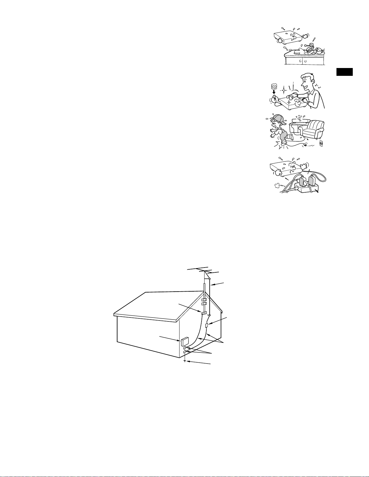
10. Outdoor Antenna Grounding
If an outside antenna or cable system is connected to the product, be sure the antenna or cable system
is grounded so as to provide some protection against voltage surges and built-up static charges. Article
810 of the National Electrical Code, ANSI/NFPA 70, provides information with regard to proper
grounding of the mast and supporting structure, grounding of the lead-in wire to an antenna discharge
unit, size of grounding conductors, location of antenna-discharge unit, connection to grounding
electrodes, and requirements for the grounding electrode.
INTRODUCTION
EXAMPLE OF ANTENNA GROUNDING AS PER
NATIONAL ELECTRICAL CODE
ANTENNA
LEAD IN
WIRE
GROUND
CLAMP
ANTENNA
DISCHARGE UNIT
(NEC SECTION 810-20)
GROUNDING CONDUCTORS
(NEC SECTION 810-21)
GROUND CLAMPS
POWER SERVICE GROUNDING
ELECTRODE SYSTEM
(NEC ART 250, PART H)
S2898A
ELECTRIC
SERVICE
EQUIPMENT
NEC – NATIONAL ELECTRICAL CODE
11. Power Lines
An outside antenna system should not be located in the vicinity of overhead power lines or other electric
light or power circuits, or where it can fall into such power lines or circuits. When installing an outside
antenna system, extreme care should be taken to keep from touching such power lines or circuits as
contact with them might be fatal.
5
Page 6
IMPORTANT SAFETY
INSTRUCTIONS
12. Lightning
For added protection for this product during storm, or when it is left unattended
and unused for long periods of time, unplug it from the wall outlet and
disconnect the antenna or cable system. This will prevent damage to the
product due to lightning and power-line surges.
13. Object and Liquid Entry
Never push objects of any kind into this product through openings as they may
touch dangerous voltage points or short-out parts that could result in a fire or
electric shock. Never spill liquid of any kind on the product.
14. Attachments
Do not use attachments not recommended by the product manufacturer as they may cause hazards.
15. Accessories
Do not place this product on an unstable cart, stand, tripod, bracket, or table.
The product may fall, causing serious injury to a child or adult, and serious
damage to the product. Use only with a cart, stand, tripod, bracket, or table
recommended by the manufacturer, or sold with the product. Any mounting of
the product should follow the manufacturer’s instructions, and should use a
mounting accessory recommended by the manufacturer.
A product and cart combination should be moved with care. Quick stops,
excessive force, and uneven surfaces may cause the product and cart
combination to overturn.
S3125A
16. Damage Requiring Service
Unplug this product from the wall outlet and refer servicing to qualified service personnel under the
following conditions:
a) When the power-supply cord or plug is damaged.
b) If liquid has been spilled, or objects have fallen into the product.
c) If the product has been exposed to rain or water.
d) If the product does not operate normally by following the operating instructions. Adjust only those
controls that are covered by the operating instructions as an improper adjustment of other controls
may result in damage and will often require extensive work by a qualified technician to restore the
product to its normal operation.
e) If the product has been dropped or damaged in any way.
f) When the product exhibits a distinct change in performance - this indicates a need for service.
17. Servicing
Do not attempt to service this product yourself as opening or removing covers
may expose you to dangerous voltage or other hazards. Refer all servicing to
qualified service personnel.
18. Replacement Parts
When replacement parts are required, be sure the service technician has used replacement parts
specified by the manufacturer or have the same characteristics as the original part. Unauthorized
substitutions may result in fire, electric shock, or other hazards.
19. Safety Check
Upon completion of any service or repairs to this product, ask the service
technician to perform safety checks to determine that the product is in proper
operating condition.
6
Page 7

Contents
INTRODUCTION
Provides important notes and general
explanation of the VCR, including names of the
buttons, jacks, etc.
SAFETY PRECAUTIONS .................... 2
IMPORT ANT PRECAUTIONS.............. 3
IMPORT ANT SAFETY
INSTRUCTIONS................................... 4
Contents .............................................. 7
Identification of Controls ................... 8
• Front Panel
• Remote Control
• VCR Display
• Rear Panel
INTRODUCTION
Variable Speed Playback.................. 21
• Picture Search
• Still Picture
• Slow-motion Picture
• Frame Advance
• Double Speed Playback
• Shuttle Dial Operation
Useful Functions in T ape
Operation........................................... 23
• Counter Function
• Tape Remaining Time
• Index Search Function
RECORDING
Explains recording functions.
PREPARATION
Explains what you need to do before operating
the VCR.
How to Use the Remote Control ...... 10
Connections ...................................... 11
Auto Set Up ....................................... 14
Initial Settings Using On-screen
Display ............................................... 15
• Setting the Language
• Optional settings on the SET UP
screen
• Setting the Clock
Storing Channels on the VCR .......... 17
Video Cassette Use .......................... 19
PLAYBACK
Explains variable functions concerning
playback.
Recording a TV Program .................. 25
• Watching a TV program while
recording another
• Recording off time setting
Timer Program Recording ............... 26
3
VCR Plus+ C
VCR Plus+ C
®
system Set-up ......... 29
3
®
system Recording .. 31
Cable Box Set-up .............................. 33
®
DSS
Satellite Receiver Set-up........ 37
MTS Broadcast Compatibility.......... 41
Simulcast Recording ........................ 42
ADDITIONAL INFORMATION
Multi Brand Remote Control ............ 43
Before Calling Service Personnel ... 45
Specifications ................................... 47
Accessories....................................... 47
Playback ............................................ 20
•19µ HEAD
LIMITED W ARRANTY ........................ 48
7
Page 8
INTRODUCTION
Identification of Controls
See the page in for details.
This manual shows the names of buttons in italics.
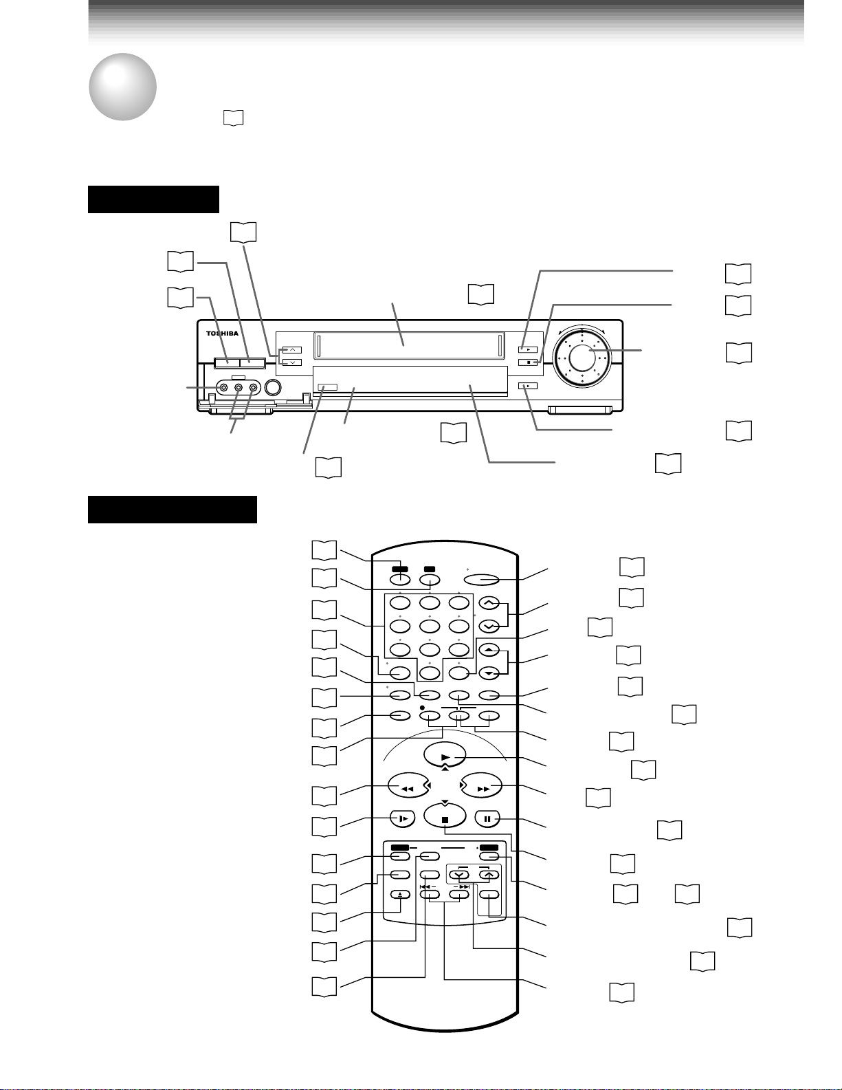
Front Panel
CHANNEL
EJECT
POWER
LINE IN 2
19
15
POWER
LINE IN 2
VIDEO L-MONO-AUDIO-R
VIDEO jack
LINE IN 2 AUDIO
(L/MONO, R) jacks
Remote Control
To operate this VCR.
To operate your TV.
Number buttons
REMAIN/COUNTER
VCR Plus+
25
c EJECT
CHANNEL
REC
VCR
TV
I.SELECT
DISPLAY
SP/SLP
REC
REW
SLOW
PROG.
EJECT
CANCEL
Cassette compartment
REC
Remote sensor
10
25
14
43
VCR TV
23
25
25
23
23
1
4
78
I.SELECT
0
REMAIN/
DISPLAY
COUNTER
SP/SLP
REC
COUNT RESET
25
SLOW
PLAY/x2
CURSOR
STOP
25
*
20
21
PROG. ENTER
CANCEL
+
15
A.SELECTVCR Plus
EJECT INDEX
31
19
28
65
9
100
19
POWER
CH/TRK
TV VOL
TV/VCR
TIMER
FFREW
PAUSE/STILL
19
µ
/
CH
POWER
CABLE
BOX
PLAY
STOP
PAUSE/STILL
REV
(
FWD
)
PAUSE/STILL
VCR display
POWER
CH/TRK
100
TV VOL
TV/VCR
15
25
18
43
25
COUNT RESET
TIMER
PLAY/x2
FF
27
*
20
*
20
PAUSE/STILL
STOP
ENTER
*
20
15
POWER (CABLE BOX)
CH (CABLE BOX)
PLAY
STOP
SHUTTLE
9
23
21
19
µ
20
35
20
20
22
21
35
8
A.SELECT
41
INDEX
24
* These buttons are used to control the
cursor on the screen.
Page 9
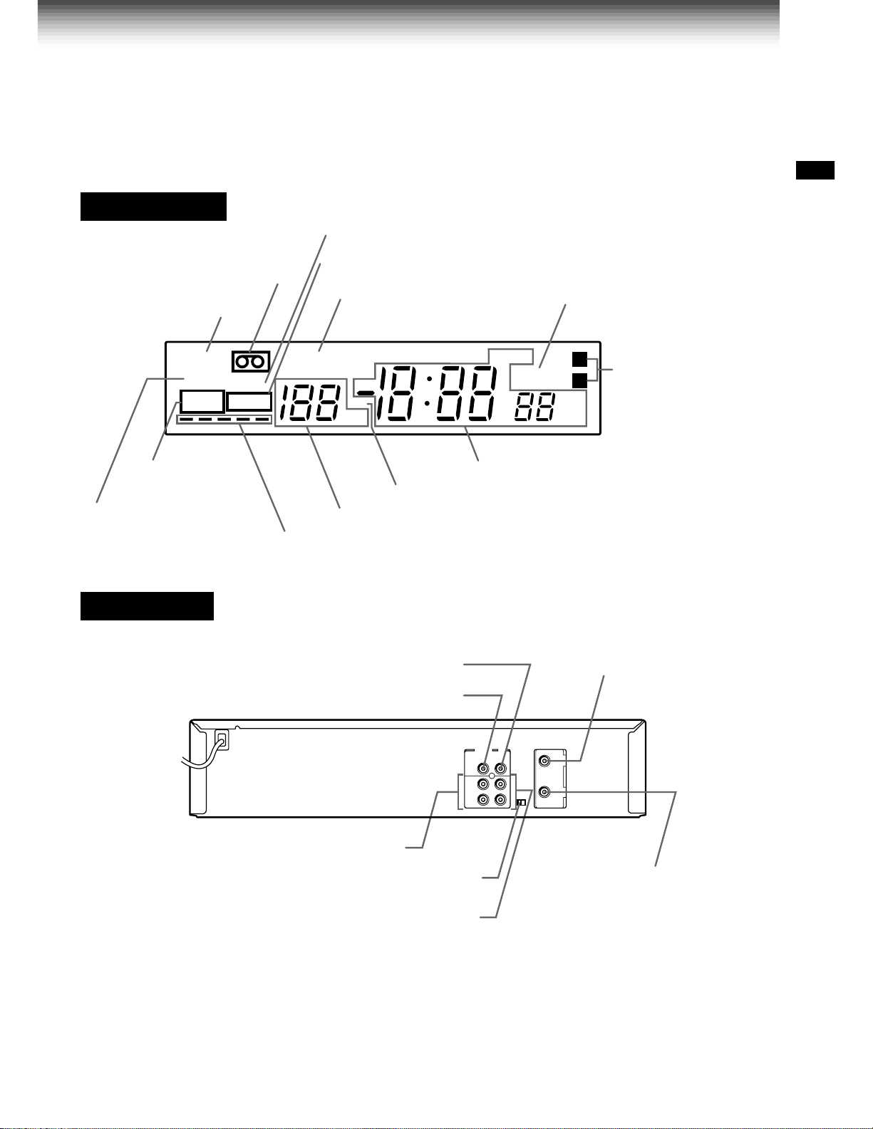
VCR Display
Cassette indicator
POWER indicator
POWER
SLP
REC
VCR
TIMER
VCR indicator
Timer recording indicator
REMAIN indicator
REMAIN
DT
CH
HM
OFF indicator
PM
AM
OFF
INTRODUCTION
L
R
Hi-Fi (L/R) indicators
L: Left channel
R:Right channel
S
off: Normal track
REC (Recording)
indicator
Tape speed indicator
(SP/SLP)
Rear Panel
To wall outlet
LINE IN 1 AUDIO jacks (L, R)
Multifunctional indicator
DT (Digital Auto Tracking) indicator
Channel indicator
Tape running direction/speed indicator
LINE OUT VIDEO jack
LINE IN 1 VIDEO jack
CH selector (3/4)
RF IN (FROM ANT.) terminal
RF OUT (TO TV) terminal
LINE OUT AUDIO jacks (L, R)
LINE IN 1 AUDIO (Rear), 2 (Front) jacks
If the connected equipment is monaural (has one audio output jack), connect the L (MONO) side, the same
sound is recorded on both L and R on the Hi-Fi track.
9
Page 10
PREPARATION
How to Use the Remote Control
This section explains how to get ready for remote control operation.
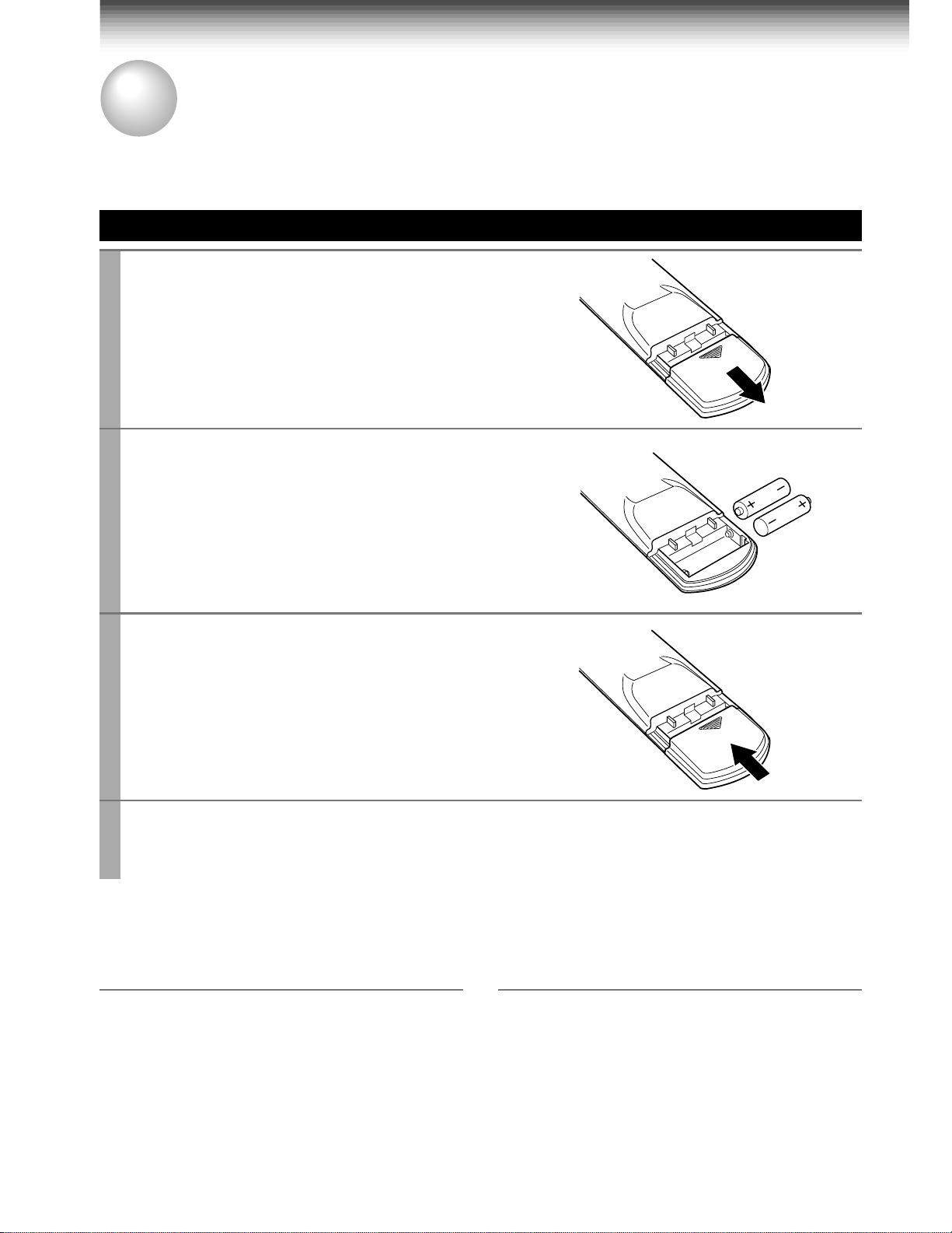
Setting up the Remote Control
Open the battery compartment lid on the
1
rear panel.
Install 2 batteries (“AAA” size) following
2
the polarity diagrams.
Close the battery compartment lid.
3
Point the remote control at the VCR and press the buttons within the operating range.
4
Distance: within about 7 m from the front of the remote sensor
Angles: within about 30˚ in every direction
Notes on batteries
• The life of the batteries is about 1 year
depending on the conditions of use.
• If the remote control does not operate correctly,
replace all batteries with new ones.
• If the remote control is not to be used for a
long period of time, remove the batteries to
avoid possible damage from battery corrosion.
Caring for the remote control
• Do not expose the remote sensor of the VCR
to a strong light source such as direct sunlight
or illumination (especially high-frequency
lighting) when using the remote control.
• Be careful not to spill water on the remote
control or to place it on anything wet, and avoid
sharp impacts.
10
Page 11
PREPARATION
Connections
Before you use this VCR, it is necessary to connect it to your TV. Several ways of connecting are
available depending on your use of TV or cable box. Select one which is applicable to your equipment.
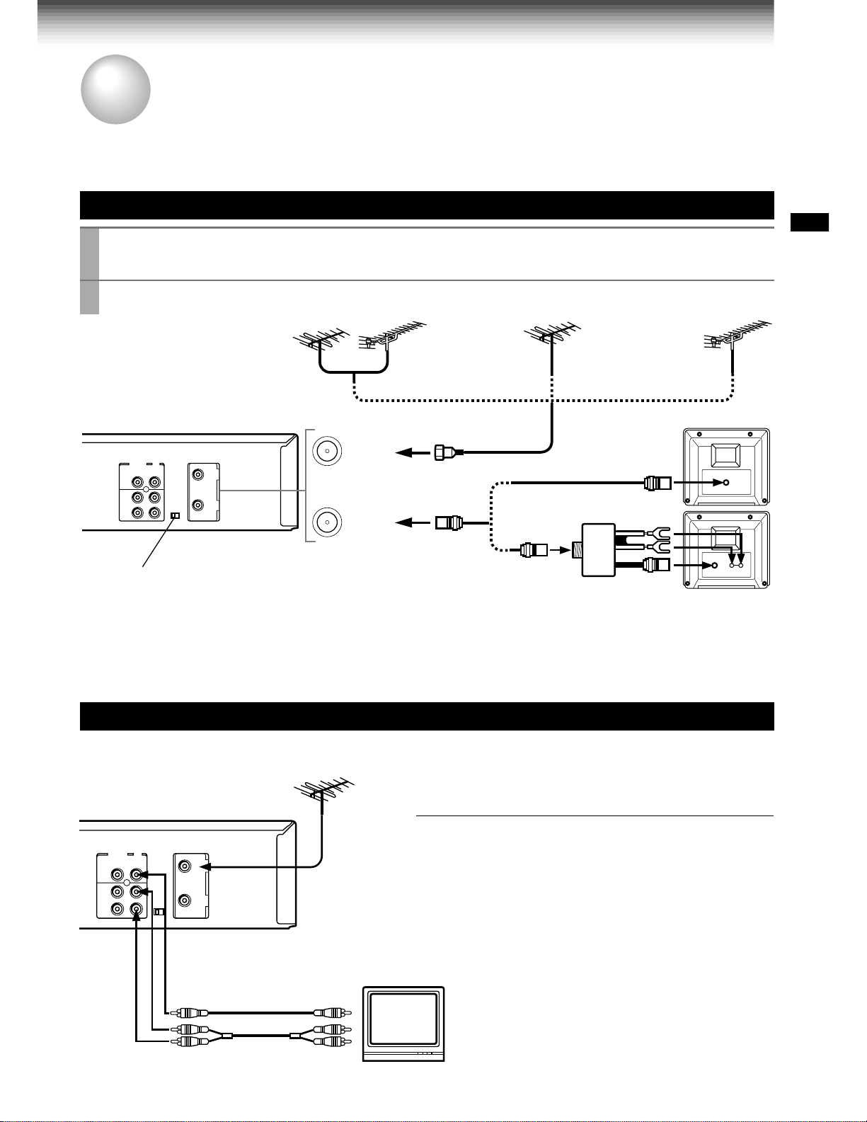
Antenna/VCR/TV Connection
Disconnect the antenna cable from your TV and connect it to the RF IN terminal on the
1
VCR.
Connect the RF OUT terminal to the TV.
2
PREPARATION
VHF/UHF combinaion
antenna
VHF antenna
only
1
IN
(FROM ANT.)
2
OUT
(TO TV)
Setting the VCR Output Channel
When the VCR is connected in this way, the VCR sends the output
signals to channel 3 or 4 on your TV. Set the output channel
selector (CH selector) of the VCR to “3” or “4”, whichever is vacant
in your area.
AUDIO/VIDEO Connections
The AUDIO/VIDEO jacks are also available to connect your TV.
UHF antenna
only
VHF/UHF
VHF UHF
Antenna splitter
(not supplied)
LINE OUT VIDEO
When connected your TV using the
AUDIO/VIDEO OUT jacks
To watch video pictures, set the video input mode on
your TV. For the video input mode, refer to the
manual of your TV.
VIDEO IN
AUDIO INLINE OUT AUDIO
11
Page 12
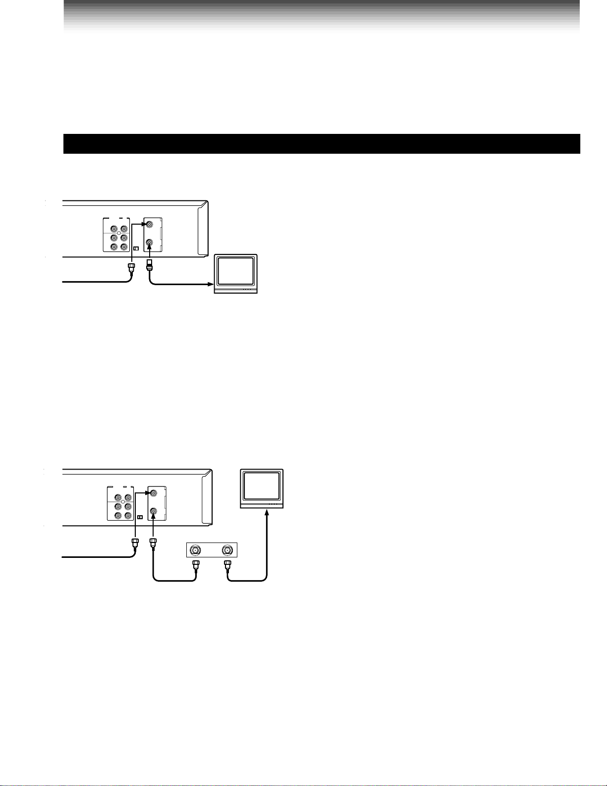
Connections (continued)
Cable Connection
Choose one of the below according to your usage of the cable box.
This set-up will enable you to:
– record an unscrambled channel.
– watch an unscrambled channel while recording
it.
– record an unscrambled channel while watching
another (only when you connect a cable-
Incoming cable
compatible TV).
You will need to:
• select TV channel 3 or 4 to receive video
signals. (See page 11.)
• to record a channel while watching another,
press
TV/VCR
the “VCR” indicator in the VCR display and
select a desired channel on the TV (only when
you connect a cable-compatible TV).
on the remote control to turn off
Incoming cable
Cable Box
IN OUT
This set-up will enable you to:
– record an unscrambled channel.
– watch an unscrambled channel while recording
it.
– record an unscrambled channel while watching
another (scrambled or unscrambled).
You will need to:
• set TV channel to the output channel of the
cable box.
• turn on the cable box and select cable channel
3 or 4 according to the output channel of the
VCR.
• to record a channel while watching another,
press
TV/VCR
the “VCR” indicator in the VCR display and
select a desired cable channel on the cable
box.
on the remote control to turn off
12
Page 13
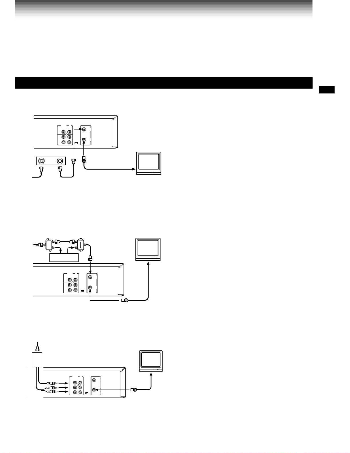
Cable Box
Cable Box
PREPARATION
This set-up will enable you to:
– watch an unscrambled or scrambled channel
while recording it.
– record any channels through the cable box.
You will need to:
OUTIN
A/B switch
A
A
A
B
B
B
• set TV channel 3 or 4 to receive video signals.
(See page 11.)
• set VCR channel to the output channel of the
cable box, and select a desired cable channel
on the cable box.
• while the VCR is turned off or the “VCR”
indicator is not lit in the VCR display, set TV
channel to the output channel of the cable box.
This set-up will enable you to:
– watch an unscrambled or scrambled channel
while recording it.
– record an unscrambled channel while watching
another unscrambled channel (only when you
connect a cable-compatible TV).
• A/B switch “A”: record and watch an
unscrambled channel which
comes bypassing the cable box.
• A/B switch “B”: record and watch a scrambled
or unscrambled channel coming
through the cable box.
This set-up will enable you to:
Box
Cable
– watch or record a channel through the cable
box via the LINE IN 1 (AUDIO/VIDEO) jacks.
You will need to:
• press
I.SELECT
shows “L1”.
so that the VCR display
13
Page 14
PREPARATION
Auto Set Up
The Auto Set Up function automatically sets the tuner channels and clock when power is first connected
to the VCR.
Preparation
• Turn on the TV, and select the video channel (3 or 4), or the video input mode if you made the Audio/Video
connection (page 11).
• Press
• Press
1
I.SELECT
VCR
so that the channel number will appear if “L1” or “L2” is displayed in the VCR display.
to set the remote control operating the VCR.
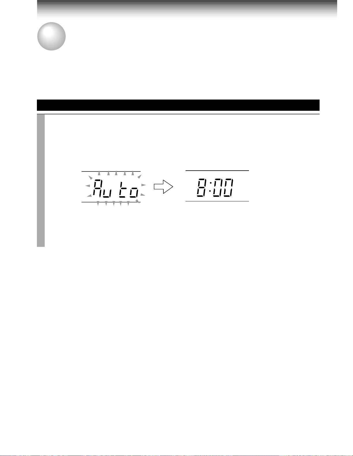
Auto Set Up
Connect the antenna cable to the VCR (see page 11). Then connect the VCR’s power
plug to an AC outlet.
“Auto” flashes in the VCR display as the VCR automatically tunes in all active stations.
When Auto Set Up is completed successfully, the current time will be displayed.
VCR display
Tuning in progress.
VCR display
PM
Auto Set Up completed.
• If the VCR fails to set the clock, “– : – –” will be displayed. Set the clock manually. (Refer
to “Setting the clock” on page 16.)
Notes
• If you press the
• If Auto Set Up is not perform successfully, perform the clock and Tuner Channel procedures manually
(page 16 to 18).
• If, however, you want to add or delete channels, refer to “Adding or erasing channels” on page 18.
CANCEL
button, the Auto Set Up is cancelled.
14
Page 15
PREPARATION
Initial Settings Using On-screen Display
Language selection must be set first when the VCR is first plugged in, or after it encounters a power
failure. You can also easily make necessary settings using the on-screen displays.
Preparation
• Turn on the TV, and select the video channel (3 or 4), or the video input mode if you made the Audio/Video
connection (page 11).
• Press
23
1
4
78
0
PLAY/x2
STOP
VCR
to set the remote control operating the VCR.
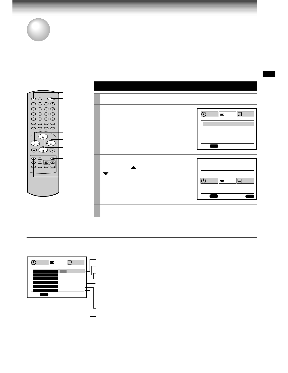
Setting the Language
VCR
POWER
65
9
100
REW
FF
FFREW
PLAY/x2,
STOP
ENTER
PROG.
1
2
Press
Press
POWER
PROG.
to turn on the VCR.
.
The following screen appears on the TV.
Select the language using
3
(
CURSOR
) or
) , and press
The screen turns to the MENU screen.
PLAY/x2
STOP (CURSOR
PROG.
.
n
ED:
PROGRAM
PROG
PROGRAM
SET UP
E
n
GLSIH
n
FRA
E
SPA
MEnU
SET UP
ÇA I
ñ
OL
PRESET
S
PRESET
PREPARATION
4
Press
PROG.
to return to the normal TV screen.
Optional settings on the SET UP screen
Other optional settings can be made. Press
ENTER
while “SET UP” is selected on the
MENU screen. The screen turns to the SET UP screen.
PROGRAM
TAPE L E
SAP SET
SIMULCAST
ANTE A
nn
LA
n
GUAG
X
DS InOF
PROG
n
ED:
GT
n
E
SET UP
H
120 016 801
n
OFFO
n
OFFO
O
UAT
n
EG RFA SPE
n
OFFO
PRESET
M
UA
n
Page 23
Page 41
Page 42
With “AUTO” set, a TV broadcast will appear via the TV tuner after
playback.
Move down here, and set to “AUTO” or “MANU”.
If you made the Audio/Video connection (page 11), set to “MANU”.
To change the language, move down here and set to the desired one.
With “ON” set, you can see the station ID and program title displayed on
TV.
n
ED:
PROG
ENTER
To exit, press
PROG.
(Continued)
15
Page 16

Initial Settings Using On-Screen Display (continued)
Setting the Clock
Example: To set the clock to 2:30 p.m. on
August 25 (summer time) 2000.
Press
1
The MENU screen appears on the TV.
Select “PRESET” using FF or
2
press
Press
3
Select “AUTO” or “MANU” using
4
x2
AUTO: The VCR automatically sets or
adjusts the clock.
If you select “AUTO” mode, proceed to step 8.
MANU: You can set the clock manually.
If you select “MANU” mode, select “SUMMER
TIME” using
summer (daylight saving) time using
or
the description in step 9.)
Move to the ne xt using FF.
5
(To move back, press
Vary the digits to set the hour.
6
PLAY/x2
STOP
Repeat steps 5 and 6 to set the minutes,
7
month, day, and the year (by the last two
digits).
Proceed to step 10 to start the clock.
PROG.
ENTER
ENTER
or
STOP
STOP
. (For “IN” and “OUT” selections, see
.
.
PROGRAM
CLOCK S
CH
CABLE B
GU IDE HC
PROG
n
ED:
to select “CLOCK SET”.
PROGRAM
CL
O
CK SET
SUMME
MA U
n
TOU1000SA1’/
12 :
PROG
n
ED:
.
FF
. Set to “IN” or “OUT” for the
REW
.)
: To increase.
: To decrease.
REW
SET UP
ET
MEMO
RY
OX / D S S
SET UP
M
ERTI
AA
TED
M
E
A
00
M
PLAY/
PLAY/x2
, and
PRESET
PRESET
ENTER
RYETI
8
Press
ENTER
to start the “AUTO” clock
set feature.
After a while, the VCR automatically updates
the clock using the data broadcast by the
local TV stations.
The following screen will appear on TV
depending on the broadcast at your location.
PROGRAM
CL
O
AUTO AUTO AUTO AUTO
PROG
n
ED:
Select the options using FF or
9
Change the data using
STOP
.
SET UP
CK SET
SUMME
M
n
I
EAS
M
E
A
57
M
:
9
PLAY/x2
M
ERTI
E
TER
AR
TED
10 00SA1’/
REW
1) Set “SUMMER TIME (DaylightSaving Time)”.
IN, daylight-saving time begins on the first
Sunday in April. Because the clock
automatically changes from 2:00 AM to
3:00 AM (forward one hour), remember
that any part of a scheduled Timer
Recording that falls between these two
times will not be recorded.
OUT, daylight-saving time ends on the last
Sunday in October. The VCR clock
automatically changes from 2:00 AM to
1:00 AM (back one hour). Therefore, it can
affect your recording length if one is set
for this time.
2) Set “Time Zone”.
If you select “AUTO” for your time zone,
the VCR sets the clock using the first
Coordinated Universal Time information it
finds. If the time is not correct, select
another time zone or use the “MANU”
option.
3) Set “CH”.
If you don't know the clock data channel,
select “AUTO”. The VCR will scan
automatically to tune the channel carrying
the clock data.
If AUTO CLOCK SET is unsuccessful, set the
time and date through the “MANU” clock set
menu selection.
Press
10
Now the clock starts.
PROG.
.
PRESET
OH
n
EZ
CTI
2
n
AEYTI
ENTER
.
or
16
11
Press
PROG.
to exit.
Page 17

PREPARATION
Storing Channels on the VCR
This section is required if you receive only normal TV or unscrambled cable channels, or use a cable box
between your TV and the VCR.
Incoming Antenna/Cable (CATV) Signals
The VCR scans through all receivable TV and CATV channels and stores only the active
ones in your area into the memory. Once the storing is finished, you can select a desired
channel using
Preparation
• Turn on the TV, and select the video channel (3 or 4), or the video input mode if you made the Audio/Video
connection (page 11).
• Press
I.SELECT
CH/TRK
.
so that the channel number will appear if “L1” or “L2” is displayed in the VCR display.
Incoming Antenna/Cable (CATV) Signals
PREPARATION
23
1
4
78
0
PLAY/x2
STOP
Press
1
65
9
100
FFREW
Number
buttons
100
I.SELECT
REW
FF
PLAY/x2,
STOP
ENTER
Select “PRESET” using FF or
2
and press
Select “CH MEMORY” using
3
x2
1, 6
Set “TV/CATV“ to “TV” or “CA TV” using FF or
4
or
PROG.
ENTER
STOP
to display the MENU screen.
REW
,
.
PLAY/
, and press
ENTER
.
PROGRAM
PROG
n
ED:
PROGRAM
TV/ C TAV
AUTO SCA
ADD CH
ERAS CEH
PROG
n
ED:
REW
SET UP
CLOCK S
MEMO
CH
CABLE B
GU IDE HC
SET UP
n
.
PRESET
ET
RY
OX / D S S
PRESET
TV TVAC
––
––
ENTER
OFFO
CH
CH
n
TV: To store channels received via the antenna.
CATV: To store channels received via the incoming cable.
Select “AUTO SCAN” using
5
or
STOP
, and press FF to set to
“ON”.
The VCR starts scanning and the
PLAY/x2
PROGRAM
TV
AUTO SCA
n
SET UP
PRESET
n
OCH2
channels are stored in the VCR in
ascending order. When the scanning is
PROG
n
finished, the screen automatically
ED:
returns.
6
Press
PROG.
to exit.
(Continued)
17
Page 18

Storing Channels on the VCR (continued)
Adding or erasing channels
Adding channels
If a desired channel cannot be scanned
automatically because of a weak signal, it can be
added to the memory.
Erasing channels
You can erase a stored channel from the memory
if it is unnecessary.
1)Follow steps 1 to 3 of “Incoming Antenna/CATV
Signals”.
2)Select “ADD CH” or “ERASE CH” using
or
STOP
.
To add channels
PROGRAM
To erase channels
TV/ C TAV
AUTO SCA
ADD CH
ERAS CEH
n
ED:
PROGRAM
TV/ C TAV
AUTO SCA
ADD CH
ERAS CEH
n
ED:
n
OSETCH
T
PUSH ~90EYSK
PROG
n
OSETCH
T
PUSH ~90EYSK
PROG
SET UP
SET UP
PLAY/X2
PRESET
TV
FFO
––
––
PRESET
TV
FFO
––
––
TVAC
n
O
n
O
n
O
TVAC
n
O
n
O
n
O
3)Enter a channel number of 1 to 125 using
number buttons
For more than 100 number, first press
.
100
.
For CATV channels, refer to the chart below.
(For other orders, check with your cable
company.)
4)Repeat steps 2) and 3) to add or erase
channels as necessary.
5)Press
PROG.
to exit.
Selecting stored channels
Once the active channels have been stored, you
can select the channels in two ways below.
Number buttons
To enter digits of the channel number.
• For one-digit number, enter 0 before.
• For more than 100 number, first press
• Each
number button
needs to be pressed
within 2 seconds.
CH/TRK
To shift up or down the stored channel numbers.
100
.
Channel reference chart
Number on the VCR
Corresponding channel number
10 11 12 13 14 15 16 17 18 19 20 21 22 23 24 25 26 27 28 29 30
10 11 12 13 14 15 16 17 18 19 20 21 22 23 24 25 26 27 28 29 30
10 11 12 13 A B C D E F G H I J K L M N O P Q
31 32 33 34 35 36 37 38 39 40 41 42 43 44 45 46 47 48 49 50 51
31 32 33 34 35 36 37 38 39 40 41 42 43 44 45 46 47 48 49 50 51
R S T U V W AA BB CC DD EE FF GG HH II JJ KK LL MM NN OO
52 53 54 55 56 57 58 59 60 61 62 63 64 65 66 67 68 69 70 71
52 53 54 55 56 57 58 59 60 61 62 63 64 65 66 67 68 69 – –
PP QQ RR SS TT UU VV WW XX YY ZZ AAA BBB 65 66 67 68 69 70 71
93 94 95 96 97 98 99 100 101 102 103
–––––––––––
93 94 A-5 A-4 A-3 A-2 A-1 100 101 102 103
CATV signals
• STD (standard) cable TV signals
• HRC (Harmonic Related Carriers) cable TV signals
• IRC (Incremental Related Carriers) cable TV signals
IRC is also called ICC (Incremental Coherent Carriers)
TV
CATV STD (HRC/IRC)
18
123456789
–23456789
1(A-8)
…
…
…
234
121 122 123 124 125
–––––
121 122 123 124 125
5(A-7) 6(A-6)
7
89
…
…
…
Page 19

PREPARATION
Video Cassette Use
Video Cassette Use
Loading a cassette
Push the cassette into the cassette compartment with the window side facing up and the
label side towards the front. The VCR is automatically turned on. The indicator will
appear in the VCR display.
Ejecting a cassette
Press
EJECT
. The cassette is ejected from the cassette compartment.
PREPARATION
Warning
Do not insert your hands or any foreign objects into the compartment. This may result
in injury or damage. Take special care with children to avoid accidents.
Precautions when using video cassettes
Video cassettes have a safety tab to prevent accidental erasure. If the tab has already been removed,
recording cannot be performed.
To prevent accidental erasure
Remove this safety tab with a screwdriver.
T o record again
Cover the tab hole with adhesive tape.
• Avoid exposing cassettes to direct sunlight. Keep them away from heaters.
Avoid extreme humidity, vibrations or shock, strong magnetic fields (near a motor, transformer or
magnet) and dusty place.
19
Page 20

PLAYBACK
K
Playback
This section explains the basic playback operation.
Preparation
• Select the video channel (3 or 4) or video input mode on the TV.
VCR
• Press
to set the remote control operating the VCR.
Basic Playback
Load a recorded cassette.
1
Pow er is turned on.
If the cassette has no safety tab,
playback starts automatically.
2
Press
PLAY/x2
23
1
4
78
0
PLAY/x2
STOP
VCR
65
9
100
CH/TR
2
FFREW
FF
3
µ
19
REW
Adjusting the tracking
When playback starts, the VCR
automatically adjusts the tracking for clear
pictures and sound (Digital Auto Tracking).
The “DT” indicator blinks during the
adjusting.
If the VCR cannot locate the best possible
tracking point, hold down one of
adjust the tracking manually.
• To resume the digital auto tracking, hold
down both
simultaneously for about 2 seconds.
Notes
• During the adjusting, the playback picture and
sound may be distorted.
• The digital auto tracking is activated only in the
playback mode.
• To reset the manual tracking point to the center,
press both
simultaneously for not longer than 1 second.
• The noise on the screen may not be completely
eliminated depending on the tape used,
especially when the tape was recorded on
another VCR.
CHANNEL
CHANNEL
on the VCR
on the VCR
T o stop pla yback, press
3
Rewinding / Fast-forwarding
REW
Press
CH/TRK
or FF in the stop mode.
to
POWER
to start playback.
STOP
.
POWER
SP
VCR
DT
19µ HEAD
You can view high quality pictures while
playing back a tape recorded in the SLP tape
speed.
By pressing
mode is displayed on the TV screen as
follows:
19U-HEAD AUTO: Usually set to “AUTO”. As
the playback starts, the VCR automatically
activates the 19µ head and reproduces high
quality pictures.
19U-HEAD OFF: Set to “OFF” if the
pictures are marred by dots.
Note
During playback with the 19µ head, momentary
noises or shakes may be produced when you
change the mode to the picture search or
variable speed playback.
19
µ repeatedly, the 19µ HEAD
20
Page 21

PLAYBACK
Variable Speed Playback
You can play back a tape at various tape speeds.
Picture Search
23
1
4
78
0
PLAY/x2
STOP
65
9
100
PLAY/x2
REW
FFREW
FF
PAUSE/STILL
SLOW
A tape runs at 5 times or 7 times the normal playback speed so
that you can quickly locate a particular scene.
Press FF or
1
The tape runs at 5 times the normal playback speed.
To change the tape speed to 7 times the normal playback
2
REW
speed, press and hold
If you release it, the tape speed returns to 5 times.
Note
FF
or
REW
If you press
forwarding or rewinding.
during picture search, the mode changes to fast-
during playback.
FF
or
REW
PLAYBACK
.
To resume normal playback
Press
PLAY/x2
Still Picture
A picture freezes so that you can watch
closer.
Press
1
The picture freezes.
To resume normal playback
Press
Notes
• The still mode is automatically cancelled after
about 5 minutes and returns to normal playback.
• The still picture may shake if a picture of a fastmoving object or scene is frozen. This is not a
defect in the unit.
Adjusting Still Picture Stability
If the still picture is distorted or flickers, hold
down one of
stable.
Note
The distortion of the still picture may not be
eliminated completely.
Note
When playing back a tape which is recorded in S-VHS format, distortion may occur during the variable speed
playback.
PAUSE/STILL
PAUSE/STILL
CH/TRK
until the picture becomes
during playback.
.
.
Slow-motion Picture
The tape runs at 1/7th or 1/15th the normal
playback speed.
Press
1
The tape runs at about 1/7th the normal
playback speed.
Each time you press
alternates between 1/7th and 1/15th.
To resume normal playback
Press
Notes
• The slow-motion picture mode is automatically
cancelled after about 5 minutes and returns to
normal playback.
• The slow-motion picture may flicker up and down.
This is not a defect in the unit.
Adjusting the Tracking Manually
If the slow-motion picture is noisy, hold down one
of
CH/TRK
Note
The noise in the slow-motion picture may not be
eliminated completely.
SLOW
PLAY/x2
until the best picture is obtained.
during playback.
SLOW
, the speed
.
(Continued)
21
Page 22

Variable Speed Playback (continued)
Frame Advance
A picture advances frame by frame.
Press
1
Each time you press
advances one frame.
If you press and hold
at 1/30th the normal playback speed.
PLAY/x2
during still playback.
PLAY/x2
PLAY/x2
, the picture
, the tape runs
To resume normal playback
Press
PAUSE/STILL
.
Shuttle Dial Operation
You can also activate the picture search and slow playback at
various speeds by turning the shuttle dial on the VCR.
Turn the
1
shuttle dial
o
i
t
c
e
r
i
d
k
c
a
b
y
a
l
P
Rewinding
v
e
R
:
n
Rewinding
Picture
search
Double Speed Playback
A tape runs at twice the normal speed.
Press
1
The picture runs at twice the normal playback
speed.
To resume normal playback
Press
on the VCR.
e
s
r
e
Picture
search
–x5
–x7
Reverse
playback
PLAY/x2
PLAY/x2
Initial mode of tape operation
R
ew
inding
Reverse
playback
–x1
playback
Reverse
playback
–x1
–x1
Stop
Playback
Reverse
Still
–x1
1/15
x
.
Slow
1/7
x
ouble
D
x2
x1
F
speed
during playback.
arding
ast-
forw
playback
Picture
search
x5
Slow
Normal
x7
playback
P
Fast-
forwarding
Picture
Search
l
a
y
b
a
c
k
d
i
r
e
c
t
i
o
n
:
F
o
r
w
a
r
d
Fast-
forwarding
The playback speeds differ depending on the recording tape speed of
the tape as follows.
Picture search Reverse playback
SP: x5 x7 -x1
SLP: x15 x21 -x3
Notes
• The still picture mode will be released automatically after about 5 minutes
and forward playback will start.
• Fast-forwarding or rewinding started from the stop mode continues even if
the
shuttle dial
is released. To stop, press
STOP
.
• The reverse playback mode will be released automatically after about 25
seconds and forward playback will start.
• Noise bar may appear in reverse playback.
Note
If you playback a tape recorded in the SLP tape speed or a tape recorded on another VCR in various speed
mode, the picture may be noisy or monochrome.
22
Page 23

PLAYBACK
Useful Functions in Tape Operation
These functions will help your playback.
S-VHS Quasi Playback (SQPB)
• This VCR can also play back a tape which is recorded in S-VHS format.
But the playback picture does not have the same quality and resolution as
the original S-VHS playback picture.
• This VCR cannot record in S-VHS format.
23
1
4
78
0
PLAY/x2
STOP
* SQPB is an abbreviation for
S-VHS Quasi Playback.
PLAYBACK
Counter Function
65
9
100
REMAIN/
COUNTER
COUNT RESET
DISPLAY
PLAY/x2
FFREW
STOP
ENTER
PROG.
You can view the clock, linear time counter or tape remaining
time in the VCR display or on the TV screen.
Each time you press
1
REMAIN/COUNTER
, the VCR display
changes in sequence as follows:
→ Linear time counter (HMS) → Tape remaining time (REMAIN/RT) → Clock
The indication above will also appear on the TV screen by pressing
DISPLAY
. They are s witchab le with
REMAIN/COUNTER
.
To reset the linear time counter to “0H00M00S”
The counter is automatically reset to “0H00M00S” when a cassette is
ejected. If you want to reset at another point, such as the beginning of a
new recording, just press
Notes
• The linear time counter does not work on non-recorded portions on the tape.
• When the tape is ejected or the VCR is turned off, the display changes to
clock.
• If the tape rewinds back over “0H00M00S”, “–” appears in the VCR display.
• The displayed time of the linear time counter is only an approximation.
COUNT RESET
.
Tape Remaining Time
To view the tape remaining time in the VCR display, select the
tape length beforehand.
Turn on the VCR and load a cassette.
1
Press
2
Select “SET UP” using FF or
3
Select the length of the tape.
4
T120: for a T-120 tape or shorter
T160: for a T-140 or T-160 tape
T180: for a T-180 tape
PROG.
to display the MENU screen.
REW
, and press
TAPE L E
SAP SET
SIMULCAST
ANTE A
LA
X
DS InOF
n
ED:
PROGRAM
nn
n
GUAG
PROG
ENTER
SET UP
H
GT
n
120 016 801
OFFO
OFFO
UAT
E
n
EG RFA SPE
OFFO
.
PRESET
n
n
O
n
(Continued)
UA
M
n
23
Page 24

Useful Functions in Tape Operation (continued)
23
1
4
78
0
PLAY/x2
STOP
5
6
Press
Press
PROG.
to exit.
REMAIN/COUNTER
.
The remaining time (“RT - : - -”) appears in the VCR display.
Notes
• The displayed remaining time is an approximation.
• The remaining time is calculated according to the tape speed (SP or SLP)
and the cassette type.
Index Search Function
65
9
100
3
FFREW
2
The VCR can find a point where a registered index signal is on a
tape and play back for about 5 seconds. You can easily locate
the desired program by inputting the index signal.
2 1 1 2
Index search
Playback
for 5 sec.
Playback
for 5 sec.
Playback
for 5 sec.
Playback
for 5 sec.
Registering index signals
Each time a recording starts, an index signal is automatically registered.
To register it somewhere else, press
Note
A certain interval is required between the index signals: more than 1 minute in
the SP tape speed and more than 3 minutes in the SLP tape speed.
INDEX
f during recording.
Index search
Load a cassette with the index signals registered.
1
Press
2
g INDEX:To search in the reverse
INDEX f:To search in the forward
The VCR fast-forwards or rewinds the
tape. When an index signal is found, the
VCR plays back the tape for about 5
seconds, and then resumes fastforwarding or rewinding. This is repeated
each time at an index signal.
Press
3
Normal playback starts.
INDEX
in the stop or playback mode.
direction.
direction.
PLAY/x2
00000
HMS
INDEX MARK
when the desired program is found.
24
Notes
• At the very beginning of the tape, the index search may not work properly.
• If you registered the index signals on a tape recorded on another VCR, the
recording may be blurred at the index point and the index search may not
work properly.
Page 25

RECORDING
T
Recording a TV Program
This section explains the basic recording operation.
Preparation
• Select the video channel (3 or 4) or video input mode on the TV.
• If you record cable channels via the cable box, finish the cable box set-up (pages 33-36), and turn on the
cable box.
Basic Recording
Load a cassette with the safety tab attached.
1
23
1
4
78
0
PLAY/x2
STOP
65
9
100
3
2
5
4
FFREW
6
I.SELEC
Press
2
indicator appears in the VCR display .
Select a channel to record with
3
CHANNEL
or
TV/VCR
so that the “VCR”
on the VCR, or
number buttons
CH/TRK
on the remote
POWER
SLP
POWER
SLP
VCR
VCR
control.
If you see “L1” or “L2” in the VCR display, press
channel number appears.
• If you record cable channels via the cable box, make the output
channel number of the cable box or “L1” appear, depending on your
connection. (See pages 11 – 13.)
I.SELECT
CH
so that the
RECORDING
4
Press
SP/SLP
recording tape speed.
To record from other
connected equipment
In step 3, press
switch the display as follows:
LI: To record via the LINE IN
1 jacks on the rear panel.
L2: To record via the LINE IN
2 jacks on the front panel.
I.SELECT
to
SP: Suitable for general recording with
better picture and sound quality.
SLP: Suitable for tripling recording time, but with less picture and
sound quality than using the SP tape speed.
5
Press
REC
on the VCR, or
simultaneously press both
the remote control.
Recording starts.
6
Press
STOP
Watching a TV program while
recording another
1)While recording, press
“VCR” indicator.
2) Choose another channel using the channel
selector on the TV.
TV/VCR
to turn off
Skipping unnecessary scenes while
recording
Press
PAUSE/STILL
momentarily. To resume recording, press
PAUSE/STILL
Note
The VCR automatically shifts to the stop mode if the
recording pause mode continues for 10 minutes.
to stop recording
again.
to select the
REC
on
POWER
SLP
POWER
SLP
REC
VCR
VCR
to stop recording.
Recording off time setting
By setting the recording off time, the recording
stops and the VCR is turned off automatically.
While recording, press
repeatedly to set the desired off time.
Each time you press
about 4 hours later and “- : - -” appear cyclically.
POWER
SLP
VCR
REC
Notes
• To cancel the recording in progress, press
• If the VCR clock is not set, this function will not
activate.
REC
on the VCR
REC
, each half-hour up to
CH
CH
TIMERREC
CH
PM
OFF
STOP
.
25
Page 26

RECORDING
Timer Program Recording
The programmable timer allows you to record up to 6 different programs over one month.
Preparation
• Select the video channel (3 or 4) or video input mode on the TV.
• Make sure that the clock is set correctly (page 16).
• Store the channels on the VCR (pages 17 and 18).
• If you record cable channels, finish the cable box set-up (pages 33 – 36), and turn on the cable box.
• If you record satellite channels, finish the DSS
®
satellite receiver.
DSS
Timer Programming Procedure
Example: To record cable channel 25 in the SP tape speed from
9:30 p.m. until 10:00 p.m. on August 30. Today is August 25.
Load a cassette with the safety tab attached.
1
23
1
4
78
0
PLAY/x2
STOP
65
9
100
4
10
REW
FF
FFREW
PLAY/x2,
STOP
ENTER
Press
2
Select “PROGRAM” using FF or
3
REW
®
satellite receiver set-up (pages 37 – 40), and turn on the
PROG.
, and press
to display the MENU screen.
ENTER
.
PROGRAM
CH DATE O DFF SP
–– – /–– –: –– – : ––
–– – /–– –: –– – : ––
–– – /–– –: –– – : ––
–– – /–– –: –– – : ––
–– – /–– –: –– – : ––
–– – /–– –: –– – : ––
PROG
n
ED:
SET UP
O
n
PRESET
–
–
–
–
–
–
CANCEL
2, 9
Move to the ne xt using FF, and enter
4
the channel number 25 by using
PLAY/x2, STOP
buttons
.
or
number
PROGRAM
CH DATE O D
25
–– – /–– – : –– – : ––
–– – /–– – : –– – : ––
–– – /–– – : –– – : ––
–– – /–– – : –– – : ––
–– – /–– – : –– – : –
PROG
n
ED:
• To record a cable program from the connected cable box:
Enter the cable channel number by
STOP
.
number buttons, PLAY/x2
If your cable box is not remote-controllable, choose the desired
channel (1 to 125) on the cable box.
• To record a satellite program from the connected DSS
receiver:
Enter the satellite channel number (100 to 999) by
buttons
,
PLAY/x2
or
STOP
. (If a number 1 to 99 is entered, the
VCR will record a TV/CATV program on the channel, not a
satellite’s.)
If your DSS
desired channel (100 to 999) on the DSS
®
satellite receiver is not remote-controllable, choose the
®
satellite receiver.
To make corrections:
Press
REW
to move back to the item, or FF to forward.
SET UP
O
n
– / –– – : –– – :–
®
FF SP
satellite
number
PRESET
–
–
or
SLP
–
–
–
–
–
26
Page 27

Move to the ne xt using FF, and set
5
the recording date using
STOP
The date changes as follows:
.
→ 8/25 → 8/26 → … → 9/24 →
MO~FR ←
WKLY
PLAY/x2
WKLY
SA ←
SU →
or
…
PROGRAM
CH DATE OFF DPS
25 8/30
–– – /–– – : –– – : ––
–– – /–– – : –– – : ––
–– – /–– – : –– – : ––
–– – /–– – : –– – : ––
–– – /–– – : –– – : ––
n
ED:
PROG
SET UP
O
–:–– –:––
[WKLYSU]…[WKLYSA]: You can record TV programs on the same
channel on the day and time every week.
[MO~FR]: You can record TV programs on the same channel on the
day and time Monda y through Friday.
Move to the ne xt using FF, and set
6
the hour and minutes of the
recording start time.
Move to the next, and set the
7
recording off time.
PROGRAM
CH DATE OFF DPS
25 8/30:30
–– – /–– – : –– – : ––
–– – /–– – : –– – : ––
–– – /–– – : –– – : ––
–– – /–– – : –– – : ––
–– – /–– – : –– – : ––
n
ED:
PROGRAM
CH DATE OFF DPS
25 8/30 9:30
–– – /–– – : –– – : ––
–– – /–– – : –– – : ––
–– – /–– – : –– – : ––
–– – /–– – : –– – : ––
–– – /–– – : –– – : ––
n
ED:
PROG
PROG
SET UP
O
9
SET UP
O
PRESET
n
n
P
n
P
M
M
PRESET
–:––
PRESET
:00
10
SLP
–
–
–
–
–
RECORDING
SLP
–
–
–
–
–
P
SLP
M
–
–
–
–
–
Move to the next, and select the tape
8
speed (SP) using
For the tape speed “AUTO (Auto Speed
Select)”, see below.
To set another program, press
select the next line pressing
Repeat steps 4 to 8.
9
Press
PROG.
Now programming is completed.
Press both
10
The power turns off and the VCR enters
the timer standby mode.
Auto Speed Select
If you are not sure the tape is long enough for
timer program recording in the SP tape speed,
set the recording tape speed to “AUTO”.
Recording starts in the SP tape speed and the
VCR automatically selects the tape speed to
record the program to the end. If the tape length
is not long enough, the tape speed automatically
changes from SP to SLP.
.
TIMER
PLAY/x2
or
FF
STOP
STOP
, and
.
simultaneously.
.
PROGRAM
CH DATE OFF DPS
25 8/30 9:3010:00
–– – /–– – : –– – : ––
–– – /–– – : –– – : ––
–– – /–– – : –– – : ––
–– – /–– – : –– – : ––
–– – /–– – : –– – : ––
n
ED:
POWER
TIMER
SET UP
PROG
PRESET
O
n
P
P
SP
M
M
TIMERREC
Notes
• Make sure that the tape length is selected correctly
according to the tape used on the SET UP screen
(page 23).
• When the SLP tape speed is selected and the tape
length is not sufficient to record the program to the
end, the program cannot be recorded to the end.
• The picture will be distorted when playing the part
where the recording tape speed is switched from
SP to SLP with the Auto Speed Select feature.
(Continued)
–
–
–
–
–
27
Page 28

Timer Program Recording (continued)
Confirming the timer programs
(in the timer standby mode)
Press
PROG.
.
The screen for confirming will appear.
PROGRAM
CH DATE OFF DPS
25 8/30 9:3010:00
–– – /–– – : –– – : ––
–– – /–– – : –– – : ––
–– – /–– – : –– – : ––
–– – /–– – : –– – : ––
–– – /–– – : –– – : ––
n
ED:
SET UP
PROG
PRESET
O
n
P
M
After about 30 seconds, the screen disappears.
Changing/cancelling the timer
programs
1)If the TIMER indicator is lit, press both
to turn it off, and then turn the VCR on by
pressing
POWER
.
2)With steps 2 to 9, change the items.
To cancel a program, select the program you
want to cancel in step 4, and press
The line is then cleared.
3)Press both
TIMER
to return to the timer
standby mode.
TIMER
CANCEL
If a power failure occurs during the
timer program recording (including
3
®
VCR Plus+ C
system recording
(page 31))
• When a power failure has occurred, “- -:- -”
appears in the VCR display. Since the
P
SP
M
–
–
–
–
–
programmed contents have been cleared,
reset the clock and timer programming.
• When power has failed for a short time, the
colon of the current time display blinks. The
programmed contents are not affected. Reset
the clock.
Overlaps of the programs
If two timer programs overlap, the recording start
time of program 2 has priority over the recording
off time of program 1.
Overlapped portion (not recorded)
Program 1
(Start time)
.
Program 2
(Start time)
Recording or playback in the timer
standby mode
First press both
standby mode, and then press
on the VCR. The VCR will be available for use.
• Be sure to press both
the VCR to the timer standby mode after you
are finished.
TIMER
to release the timer
TIMER
POWER
again to return
to turn
Error indication
The “E” (Error) indicator appears in the VCR
display if you press both
–– a cassette is not loaded.
–– the loaded cassette has no safety tab.
–– no timer program is set.
In these cases, a recording can not be made.
TIMER
when:
28
Page 29

RECORDING
VCR Plus+ C
3
VCR Plus+ C
enter a PlusCode
necessary set-up to make VCR Plus+ C
®
system is a timer recording system for an easier programming that requires you only to
®
programming number assigned to a desired program. This section explains the
3
®
system
3
®
system recordings.
Set-up
The flow chart below will give you an idea
as to what must be done to use the VCR
3
®
Plus+ C
system feature.
Setting the Clock (page 16)
↓
Cable Box Set-up (page 33)
↓
Storing Channels on the VCR
(page 17)
↓
3
VCR Plus+ C
®
system Set-up
↓
3
VCR Plus+ C
®
system Recording
(page 31)
3
* With the VCR Plus+ C
cassette recorder can automatically select the
appropriate channel on your compatible cable
box or satellite receiver. VCR Plus+, C
PlusCode are registered trademarks of
Gemstar Development Corporation. The VCR
Plus+ system is manufactured under license
from Gemstar Development Corporation.
®
system, this video
3
and
Sample of a Guide channel chart from a local TV listing
VCR Plus+® SYSTEM CHANNEL NUMBERS
Broadcast
channels
3 KCRA (NBC).................3
6 KVIE (PBS)...................6
10 KXTV (CBS)................10
13 KOVR (ABC)...............13
19 KCSO (SPAN).............19
31 KRBK (IND).................31
40 KTXL
58 KSCH
44 KBHK
24 KCPM
4 KRNV
42 KFCB
7 KGO
(FOX)
(IND)
(IND)
(NBC)
(NBC)
(IND)
(ABC)
Assigned
channels
................40
................ 25
.................15
...............24
...............28
.................27
.................28
Cable
channels
A & E........................39
AMC.........................35
BET..........................57
BRAV.......................54
CMTV.......................14
CNBC.......................23
CNN.........................42
C-SPAN....................28
CUNY.......................29
DIS...........................53
ESPN.......................34
FAM.........................47
HBO.........................33
Assigned
channels
Sample of a Channel line-up chart from a cable-TV
company
CHANNEL LINE-UP CHART
Channel 2
Channel 3
Channel 4
Channel 5
Channel 6
Channel 7
Channel 8
Channel 9
ME/U
8 WISH
4 WTTV
6 WRTV
VCA/Local origination
HOME BOX OFFICE
A.P News Plus
9 WGN.
RECORDING
You must give the VCR the special
numbers for guide channels (also called
®
VCR Plus+
system channel numbers)
assigned to each channel that you receive
in your home. The VCR identifies the
channel to be recorded by the guide
channel number you enter.
The guide channel numbers are published
in TV guide magazine, selected local TV
publications, or the channel guide from
cable company. If you cannot find the
numbers, call Gemstar’s customer service
department at 1-800-4321-VCR.
(Continued)
29
Page 30

VCR Plus+ C
3
system Set-up (continued)
®
Preparation
• Select the video channel (3 or 4) or video input mode on the TV.
• If you record cable channels, finish the cable box set-up (pages 33 – 36).
• Prepare the list like below.
Example
Station
HBO 33 7
ESPN 34
AMC 35
Guide channel number
(on the TV Guide, local TV listings etc.)
Your home channel number (on the channel line-up
chart supplied by cable companies)
Guide Channel Setting
23
1
4
65
78
9
100
0
PLAY/x2
FFREW
STOP
Notes
• When your cable company
changes the channel lineup, you must re-do this setup for the channel.
• The VCR Plus+ C
feature does not work on
programs from a connected
®
satellite receiver.
DSS
30
7
2,4
3,6,7
ENTER
1,5,8
3
®
system
Press
1
Select “PRESET” using FF or
2
Select “CH MEMOR Y” using
3
Set “TV/CATV” to “TV” or “CATV” using FF or
4
Press
5
Select “GUIDE CH” using
6
or
Enter channel numbers on the right of the guide channel
7
PROG.
PROG.
STOP
.
REW
PLA Y/x2
or
to return to the PRESET screen.
PLAY/x2
, and press
ENTER
(the case of CATV mode)
.
, and press
STOP
, and press
REW
PROGRAM
125 125
TOSET
PROG
n
ED:
ENTER
.
SET UP
11
22
33
HC
PUSH 0~9 KEYS
numbers.
Find a guide number you marked on the list using
and enter the corresponding home channel number if necessary by
using
number buttons
.
Example: To enter home channel number
7 (HBO) with guide channel number 33
assigned.
In some areas, one channel may be
assigned more than one guide channel
number. In this case, enter the home
channel number to each of the guide
channel numbers.
8
Press
PROG.
to exit.
The set-up is all over and your VCR Plus+ C
now availab le.
PLAY/x2
PROGRAM
TOSET
n
ED:
3
®
system recording is
SET UP
30 30
131
23
337
HC
PUSH 0~9 KEYS
PROG
.
ENTER
HGU DEIHCEOMCH
HGU DEIHCE
OM
or
HGU DEIHCEOMCH
3
32
HGU DEIHCE
OM
PRESET
CH
STOP
PRESET
CH
.
,
Page 31

RECORDING
3
VCR Plus+ C
After performing the VCR Plus+ C
entering the PlusCode
®
programming number. The numbers are published in the TV listings of
®
system
3
®
system set-up, you can easily program a recording simply by
Recording
newspapers, TV guide magazine, etc.
Preparation
• Make sure that the clock is set correctly (page 16).
• Load a cassette with a safety tab.
For cable box users:
• Finish the cable box set-up (pages 33 – 36), and turn on the cable box.
For DSS
• This VCR cannot record satellite programs with the VCR Plus+ C
®
satellite receiver users:
3
®
system feature. To make an unattended
recording of satellite programs, see “Timer Program Recording” (pages 26 – 28).
Sample of TV program listing in a TV guide magazine
5PM
FAM
POPEYE
HBO
MAKING OF A CHAMPION
A look at gymnast and Olympic hopeful Kim
Zmeskal from novice to seasoned competitor.
NIK
HEY DUDE
One of Ted’s teachers stays at the ranch.
USA
5:35
MY TWO DADS
TBS
GOOD TIMES
Cartoon
Children
725692
Comedy
Comedy
793571
2261858
237945
586858
PlusCode
®
programming
number
RECORDING
23
1
4
78
0
PLAY/x2
STOP
3
VCR Plus+ C
Press
1
65
9
100
2
The VCR Plus+ screen appears.
Enter a PlusCode® programming number.
2
Example: To record a program with the
FFREW
7
REW
FF
PLAY/x2,
STOP
PROG.
5
CANCEL
PlusCode
(fictitious code).
Press
Confirm that the number is entered
correctly.
To correct a mistake, press
enter the correct number.
Select “MODE” using
3
STOP
1
frequency.
OnCE: To record once.
DAILY(MO~FR): To record programs on
VCR Plus+
®
programming number 36295
number button 3, 6, 2, 9 and 5
, and set the recording
®
system Programming
.
.
CANCEL
PLAY/x2
and
or
PROGRAM
VCR P US+L
PLUSC DEO
MODE
SPEED
OSETPLUSCODE
T
PUS SH~90EYK
PROG
n
ED:
PROGRAM
VCR P US +L
PLUSC DEO
MODE
SPEED
SET UP
n
CEMO~
O
SL
P
SET UP
n
CEMO~
O
SL
P
92
5
36
F
AUPS
O
T
592
36
F
AUPS
O
T
PRESET
–
R
WKLY
ENTER
PRESET
R
WKLY
the same channel at the same time
Monday through Friday.
n
ED:
PROG
ENTER
WEEKLY: To record programs on the
same channel at the same time on the
same day every week.
Select “SPEED” using
4
STOP
, and set the recording tape
speed.
For AUTO speed, see page 27.
PLAY/x2
or
PROGRAM
VCR P US +L
PLUSC DEO
MODE
SPEED
n
ED:
PROG
SET UP
36
n
CEMO~
O
AUPS
SL
P
(Continued)
592
F
O
T
PRESET
R
WKLY
ENTER
31
Page 32

VCR Plus+ C
3
system Recording (continued)
®
5
Press
ENTER
The program setting is now memorized.
• If your cable box is not remotecontrollable, select the recording
channel on the cable box beforehand.
To set another program, repeat steps 1 to 5.
6
To finish press the two
7
buttons simultaneously.
The VCR enters the timer standby mode.
3
Confirming the VCR Plus+ C
®
system
timer programs
Before the VCR enters the timer standby
mode (TIMER indicator not lit)
1)Press
2)Press
3)Press
PROG.
ENTER
to display the MENU screen.
to select “PROGRAM”.
Check the programmed data.
PROG.
to exit.
.
PROGRAM
CH DATE OFF DPS
25 8/30 9:3010:00
–– – /–– – : –– – : ––
–– – /–– – : –– – : ––
–– – /–– – : –– – : ––
–– – /–– – : –– – : ––
–– – /–– – : –– – : ––
PROG
n
ED:
TIMER
POWER
TIMER
Recording or playback in the timer
standby mode
First press both
standby mode, and then press
on the VCR. The VCR will be available for use.
• Be sure to press both
the VCR to the timer standby mode after you
have finished.
TIMER
to release the timer
POWER
TIMER
again to return
SET UP
O
n
PRESET
P
M
TIMERREC
to turn
P
SLP
M
–
–
–
–
–
During the timer standby mode (TIMER
indicator lit)
Press
PROG.
.
The screen for confirming appears.
After about 30 seconds, the screen disappears.
3
Canceling the VCR Plus+ C
®
system
timer programs
1)If the TIMER indicator is lit, press both
to turn it off, and turn on the VCR by pressing
POWER
2)Press
3)Press
.
PROG.
ENTER
to display the MENU screen.
to select “PROGRAM”.
4)Select a program which you want to cancel.
5)Press
CANCEL
.
The line is cleared out.
6)Press
PROG.
to exit.
TIMER
Error indications
If “FULL / CANCEL PROG?” message appears
on the TV during programming, no more
programs can be entered. If you want to add
another, delete one existing program on the
screen by using
If an incorrect PlusCode
entered, “ERROR CODE ENTERED” appears on
the screen. Press
and enter correct one.
If “CLASH” message appears on the TV during
programming, it tells you that two programs with
the same recording start time have been entered.
Correct either of the two programs as follows:
1)Select the number of the program to correct by
using
PLAY/x2
2)Correct the data, or clear out the line by
pressing
VCR Plus+
number.
PLAY/x2
or
CANCEL
or
STOP
.
®
programming number is
CANCEL
STOP
to clear the number
.
and then press
to enter a PlusCode® programming
32
Page 33

RECORDING
Cable Box Set-up
The VCR can directly control channel selecting of the connected cable box.
Cable Box Control
This VCR needs to be connected to a cable
box equipped with an infrared wireless
remote control. You can select cable
channels from the cable box by operating
this VCR.
It is also possible to automatically change
the cable channels according to your
program setting in the timer program
3
®
recording or VCR Plus+ C
system recording.
Placing the Cable Box
Put the cable box on the top of the VCR as
shown below. Do not block the sensor
window.
Cable box
Wall
Sensor window
Front of the VCR
Connection Type
Type A
RECORDING
Type B
The infrared signals come out of the sensor
window and the front of the VCR. Then they
bounce off walls and other objects in the
room and are received by the cable box.
The VCR sends out infrared signals to your
cable box even during timer program
3
®
recording or VCR Plus+ C
system
recording.
Notes
• If the channels cannot be controlled properly
because the infrared signal fails to reach the cable
box, change the position of the box on the VCR so
that it can receive the signal.
• Keep the cable box turned on even while the VCR
is in the timer program recording or VCR Plus+ C
system recording.
3
Type C
A
A/B switch
A
A
B
B
Cable box
®
Type D
Cable box
B
(Continued)
33
Page 34

Cable Box Set-up (continued)
)
)
Preparation
• Select the video channel (3 or 4) or video input mode on the TV.
• Set “TV/CATV” on the CH MEMORY screen to “CATV” (page 17).
Cable Box Set-up
23
1
4
78
0
PLAY/x2
STOP
Press
1
FFREW
Number
buttons
100
I.SELECT
REW
FF
PLAY/x2,
STOP
ENTER
65
9
100
Select “PRESET” using FF or
2
Select “CABLE BOX/DSS” using
3
ENTER
Select “NO” or “C.BOX” using FF or
4
connection type.
NO: • Type A
• Cable channels will be selected using
POWER
(CABLE BOX
CH
(CABLE BOX
PROG.
→ Go to step 8.
C.BOX: • Type B
→ Go to step 5.
Select “OUTPUT CH” using
5
PROG.
.
• Type C (A/B switch “A”)
CH/TRK
CHANNEL
on the remote control or
• Type C (A/B switch “B”)
• Type D
to display the MENU screen.
REW
, and press
PLAY/x2
REW
on the VCR.
PLAY/x2
ENTER
or
STOP
according to your
SET UP
SET UP
, and enter
USE
USE
OUT UT CHP
COnTORL
or
PROGRAM
PROGRAM
STOP
.
, and press
PRESET
C.BOXO
n
PRESET
O
n
C.BOX
3
n
OFFO
SSD
SSD
HC
either of the following according to your connection.
SET UP
O
n
(Example)
PRESET
C.BOX
3
n
OFFO
SSD
HC
Type B, C: the output channel number of
your cable box using
number buttons
.
(Usually 3 or 4. Check the rear of the
cable box.)
Type D: the line input mode “L1” using
I.SELECT
.
PROGRAM
USE
OUT UT CHP
COnTORL
34
Select “CONTROL” using
6
or “OFF” using
FF
or
REW
PLAY/x2
.
or
STOP
, and set to “ON”
ON: if your cable box is remotecontrollable.
• Cable channels will be selected by
(CABLE BOX)
on the remote control.
The VCR can change the cable
CH
PROGRAM
USE
OUT UT CHP
COnTORL
BRAnTDYPE
SET UP
n
O
C.BOX
OFFO
n
O
.
PRESET
3
n
1
SSD
HC
channel to the desired one when timer
recording or VCR Plus+ C
®
system
n
ED:
PROG
3
recording starts.
→ Go to step 7.
OFF: if your cable box is NON remote-
controllable.
• Cable channels will be selected by the
own channel selector of the cable box.
The VCR channel should be set to the
output channel of the cable box.
→ Go to step 8.
PROGRAM
USE
OUT UT CHP
COnTORL
PROG
n
ED:
SET UP
n
O
C.BOX
OFFO
PRESET
3
n
SSD
HC
Page 35

Select “BRAND TYPE” using
7
of your cable box using
STOP
, and enter a brand code
number buttons
. Refer to the table
on the next page.
Example: For a TOSHIBA cable box, identified by number 36.
PROGRAM
USE
OUT UT CHP
COnTORL
BRAnTDYPE
PROG
n
ED:
SET UP
O
n
C.BOX
OFFO
n
O
.
PRESET
3
n
63
Cable box display
SSD
HC
Cable channel number
VCR display
Make sure that the channel display of your cable box has changed to
9. If not, try each brand code assigned to the brand of your cable box
until the display changes to 9.
If it still holds;
• Relocate the cable box on the VCR.
• Use each of digits from 1 to 91.
Press
8
Notes
• If your cable channel does not change to 9 in step 7, the cable box will not
be able to change channels in the timer recording. In this case, set
“CONTROL” to “OFF” in step 6.
• The cable box control is not compatible with the DSS
control.
PROG.
to exit.
®
satellite receiver
RECORDING
Buttons to control a remotecontrollable cable box
Once you complete the set-up for a remote
controllable cable box, your cable box can be
controlled by the following buttons on the remote
control of the VCR.
•
POWER (CABLE BOX)
To turn the cable box on or off.
•
CH (CABLE BOX)
To select cable channels in the upper or lower
direction. (not applicable to some brands of
cable box.)
•
Number buttons (0 – 9)
To select desired channels to record.
•
100
Some cable boxes require you to use this
button as the enter button. Press this button
after selecting the cable channel with number
buttons.
(Continued)
35
Page 36

Cable Box Set-up (continued)
Table of cable box brand codes
Brand name of your
cable box
Toshiba 36
Anvision 13, 20, 21, 22, 23, 24, 25,
26, 58, 62, 84
Archer 1, 20, 21, 29, 42, 44, 63,
88, 91
Cablestar 13, 20, 21, 22, 23, 24, 25,
26, 58, 62, 84
Cableview 30, 42, 44, 52, 63, 88
Citizen 30, 42, 44, 52, 63, 88
Curtis 8, 9, 56, 61
Diamond 1, 20, 21, 29, 42, 44, 63,
88, 91
Eagle 13, 20, 21, 22, 23, 24, 25,
26, 58, 62, 84
Eastern 26, 28
GC Brand 30, 42, 44, 52, 63, 88
Gemini 4, 30, 85
General Instrument 1, 2, 3, 4, 31, 34, 55, 85,
91
Hamlin 14, 15, 28, 41
Hitachi 31, 79, 80
Jerrold 1, 2, 3, 4, 31, 34, 55, 85,
91
Macom 31, 79, 80
Magnavox 13, 20, 21, 22, 23, 24, 25,
26, 58, 62, 84
Movietime 29, 32, 38, 39, 42, 44, 88
NSC 29, 32, 38, 39, 42, 44, 88
OAK 10, 11, 12, 13, 46
OAK Sigma 10, 11, 12, 13, 46
Panasonic 6, 8, 16, 17
Philips 4, 13, 20, 21, 22, 23, 24,
25, 26, 58, 62, 84
Pioneer 5, 6, 78
Pulsar 30, 42, 44, 52, 63, 88
Randtek 13, 20, 21, 22, 23, 24, 25,
26, 58, 62, 84
RCA 6, 8, 16, 17
Realistic 44, 88
Regal 14, 23, 41, 84
Regency 26, 28
Rembrandt 29, 32, 38, 39, 42, 44, 88
Samsung 4, 6, 32, 42, 78
Scientific Atlanta 8, 9, 56, 61
Sheritech 27
SL Mark 4, 6, 32, 42, 78
Sprucher 6, 8, 16, 17
Stargate 4, 6, 30, 32, 42, 44, 52, 63,
78, 88
Sylvania 19
Teknika 74
Brand code
36
Brand name of your
cable box
Telecaption 77
Teleview 4, 6, 32, 42, 78
Texscan 18, 19
Tocom 1, 33, 34, 42, 48, 49, 73,
91
Unika 1, 20, 21, 29, 42, 44, 63,
88, 91
Universal 29, 42, 43, 44, 52, 63, 82,
88
Videoway 7, 23, 45, 50, 84
Viewstar 13, 20, 21, 22, 23, 24, 25,
26, 58, 62, 84
Warner Amex 6
Zenith 7, 23, 45, 50, 84
Brand code
Page 37

RECORDING
DSS® Satellite Receiver Set-up
The VCR can directly control channel selecting of the connected DSS® satellite receiver.
DSS® Satellite Receiver Control
This VCR needs to be connected to a DSS
satellite receiver equipped with an infrared
wireless remote control. You can select
satellite channels from the DSS
®
satellite
receiver by operating this VCR.
®
DSS
is registered trademark of DIRECTV,
Inc., a unit of GM Hughes Electronics.
It is also possible to automatically change
the satellite channels according to your
program setting in the timer program
recording.
Placing the DSS® Satellite
Receiver
Put the DSS® satellite receiver on the top of
the VCR as shown below. Do not block the
sensor window.
DSS® satellite receiver
Connection Type
®
Type A
Satellite
antenna
RF IN
3CH
4CH
DSS® satellite receiver
Type B
Satellite
antenna
®
DSS
satellite receiver
3CH
4CH
RF OUT
RECORDING
RF IN
RF OUT
Incoming cable
Wall
Sensor window
Front of the VCR
The infrared signals come out of the sensor
window and the front of the VCR. Then they
bounce off walls and other objects in the
room and are received by the DSS
®
satellite
receiver. The VCR sends out infrared
®
signals to your DSS
satellite receiver even
during timer program recording.
Notes
• If the channels cannot be controlled properly
because the infrared signal fails to reach the DSS
satellite receiver, change the position of the
receiver on the VCR so that it can receive the
signal.
• Keep the DSS
while the VCR is in the timer program recording.
®
satellite receiver turned on even
LINE IN 1
LINE OUT
®
(Continued)
37
Page 38

DSS® Satellite Receiver Set-up (continued)
)
)
Preparation
Select the video channel (3 or 4) or video input mode on the TV.
DSS® Satellite Receiver Set-up
23
1
4
78
0
PLAY/x2
STOP
Press
1
65
9
100
Number
buttons
Select “PRESET” using FF or
2
and press
I.SELECT
REW
FF
FFREW
PLAY/x2,
PROG.
ENTER
to display the MENU screen.
REW
,
.
n
ED:
PROGRAM
PROG
SET UP
CLOCK S
CH
MEMO
CABLE B
GU I DE HC
PRESET
ET
RY
OX / DSS
ENTER
STOP
Select “CABLE BOX/DSS” using
ENTER
POWER
(CABLE BOX
3
PLAY/x2
ENTER
.
or
STOP
, and press
PROGRAM
USE
SET UP
n
PRESET
C.BOXO
SSD
CH
(CABLE BOX
PROG.
Select “DSS” using FF.
4
PROG
n
ED:
PROGRAM
USE
OUT UT CHP
COnTORL
SET UP
O
n
C.BOX
OFFO
PRESET
3
n
SSD
HC
38
PROG
n
ED:
Select “OUTPUT CH” using
5
either of the following according to your connection.
T ype A: the output channel number of
your DSS
number buttons
the rear of the DSS
Type B: the line input mode “L1” using
I.SELECT
®
satellite receiver using
. (Usually 3 or 4. Check
®
satellite receiver.)
.
PLAY/x2
or
STOP
PROGRAM
USE
OUT UT CHP
COnTORL
OSETCH
T
PROG
n
ED:
, and enter
(Example)
SET UP
O
n
C.BOX
PUSH ~90EYSK
PRESET
3
n
OFFO
SSD
HC
Page 39

Select “CONTROL” using
6
or “OFF” using
FF
or
REW
PLAY/x2
.
or
STOP
, and set to “ON”
ON: if your DSS® satellite receiver is
remote-controllable.
• Satellite channels will be selected by
CH (CABLE BOX)
on the remote
control.
PROGRAM
USE
OUT UT CHP
COnTORL
BRAnTDYPE
The VCR can change the satellite
channel to the desired one when timer
n
ED:
PROG
recording starts.
→ Go to step 7.
OFF: if your DSS
NON remote-controllable.
• Satellite channels will be selected by
the own channel selector of the DSS
satellite receiver .
®
satellite receiver is
PROGRAM
USE
®
OUT UT CHP
COnTORL
The VCR channel should be set to the
output channel of the DSS
®
satellite
n
ED:
PROG
receiver.
→ Go to step 8.
Select “BRAND TYPE” using
7
of your DSS
®
satellite receiver using
STOP
, and enter a brand code
number buttons
to the table on the next page.
Example: For a TOSHIBA DSS® satellite receiver, identified by
number 99.
SET UP
O
n
SET UP
O
n
PRESET
C.BOX
3
OFFO
n
n
O
.
1
PRESET
C.BOX
3
n
OFFO
. Refer
SSD
HC
RECORDING
SSD
HC
PROGRAM
USE
OUT UT CHP
COnTORL
BRAnTDYPE
PROG
n
ED:
SET UP
n
O
PRESET
C.BOX
OFFO
O
n
.
VCR display
SSD
HC
3
n
99
Make sure that the background of the above display has changed to
the satellite program on channel 200. If not, relocate the DSS
®
satellite receiver on the VCR so that it can receive the infrared signal.
Press
8
Notes
• If your satellite channel does not change to 200 in step 7, the DSS
PROG.
to exit.
®
satetllite
receiver will not be able to change channels in the timer recording. In this
case, set “CONTROL” to “OFF” in step 6.
• The VCR Plus+ C
• The DSS
®
satellite receiver control is not compatible with the cable box
3
®
system recording is not available on satellite channels.
control.
(Continued)
39
Page 40

DSS® Satellite Receiver Set-up (continued)
Buttons to control a remotecontrollable DSS® satellite receiver
Once you complete the set-up for a remote
controllable DSS
satellite receiver can be controlled by the
following buttons on the remote control of the
VCR.
•
POWER (CABLE BOX)
To turn the DSS® satellite receiver on or off.
CH (CABLE BOX)
•
To select satellite channels in the upper or
lower direction. (not applicable to some brands
of DSS
•
Number buttons (0 – 9)
®
To select desired channels to record.
®
satellite receiver, your DSS
satellite receiver.)
Table of DSS® satellite receiver brand
codes
®
Brand name of your
®
satellite receiver
DSS
Brand code
TOSHIBA 99
RCA 98
SONY 97
40
Page 41

RECORDING
T
MTS Broadcast Compatibility
This VCR can receive or record MTS (Multichannel TV Sound) broadcasts. By connecting the VCR to
your stereo system or stereo TV, you will experience the SAP or stereo sound.
Preparation
Connect a stereo TV or stereo system to the AUDIO OUT jacks of the VCR.
Recording the SAP/Stereo Broadcast
On the SET UP screen (page 15),
23
1
4
78
0
PLAY/x2
STOP
1
65
9
100
FFREW
DISPLAY
1
1, 2
select “SAP SET” using
STOP
FF
Press
2
Perform a recording.
3
, and set to “ON” using
.
PROG.
to exit.
PLAY/x2
REW
or
or
1
PROGRAM
TAPE LE
SAP SET
SIMULCAST
ANTE A
nn
LA
n
GUAG
X
DS InOF
PROG
n
ED:
n
E
GT
SET UP
H
PRESET
120 016 801
n
OFFO
n
OFFO
O
UAT
M
n
EG RFA SPE
n
OFFO
UA
n
RECORDING
A.SELEC
SAP (Second Audio Program broadcast):
A separate audio program, usually broadcast in a second language with the
main language.
Selecting a sound
Sounds recorded on the tape
According to your setting of “SAP SET” on the SET UP screen, the sound is recorded onto different
tracks of the tape as below. Set “SAP SET” to “ON” or “OFF” appropriately.
Type of receiving
broadcast
Regular
(monaural audio)
Stereo
Regular+SAP
Stereo+SAP
Setting of “SAP SET”
on the SET UP
screen
“ON” or “OFF” not lit not lit MONO MONO MONO
“ON” or “OFF” not lit lit MONO (MIXED)
“ON” lit not lit MONO MONO SAP
“OFF” lit not lit MONO MONO MONO
“ON” lit lit MONO MONO SAP
“OFF” lit lit MONO (MIXED)
On-Screen Display
(Press
DISPLAY
.)
Contents of recorded sound
Normal sound
track (Mono)
Hi-Fi sound track
L
STEREO
STEREO
R“SAP” “STEREO”
Sounds in playback
You can play SAP and/or stereo broadcasts with this VCR. Press
Desired sound
SAP sound
Stereo sound
L , R indicators in the VCR display
R (right) is on.
Both R (right) and L (left) are on.
A.SELECT
Sound output
SAP
Stereo
to select a desired sound.
Note
When the TV is connected to the RF OUT terminal of the VCR, the output sound is monaural.
41
Page 42

RECORDING
Simulcast Recording
When TV program such as MTV, HBO or MAX is being simulcast in FM stereo in your area, the VCR can
also record the simulcast sound from an FM stereo tuner or receiver onto the Hi-Fi track and normal
track.
Preparation
• Connect the TV and stereo system to the VCR as below.
• Turn on the connected FM tuner and tune to the station for the simulcast program.
To the FM antenna terminal
Broadcast or
incoming cable
23
1
4
78
0
PLAY/x2
STOP
AUDIO OUT
65
9
100
FFREW
3
4
5
1
6
1
1, 2
LINE IN 1 AUDIO
Simulcast Recording
On the SET UP screen (page 15),
1
select “SIMULCAST” using
or
or FF.
Press
2
Select the desired channel using
3
CH/TRK
If you use a cable box, select a desired channel on the box.
Select the recording tape speed using
4
AUDIO IN
STOP
PROG.
AUDIO OUT
PLAY/x2
, and set to “ON” using
to exit.
on the remote control.
REW
CHANNEL
SP/SLP
nn
GUAGE
PROG
GT
n
SET UP
H
120 016 801
EG RFA SPE
PROGRAM
TAPE LE
SAP SET
SIMULCAST
ANTE A
LA
n
X
DS InOF
n
ED:
on the VCR or
.
PRESET
n
OFFO
n
OFFO
O
UAT
M
n
n
OFFO
UA
n
42
5
6
Press
Press
REC
to start recording.
STOP
to stop recording.
Page 43

ADDITIONAL INFORMATION
2
0
PROG.
T
Multi Brand Remote Control
The remote control can be compatible with various brands of TV by setting their control codes. The
TOSHIBA code has initially been set to control TOSHIBA TVs.
Setting Control Codes
23
1
4
78
0
PLAY/x2
STOP
1
POWER
FFREW
CH/TRK
TV VOL
100
Number
buttons
DISPLAY
I.SELEC
ENTER
65
9
100
2, 3
Press TV to set the remote control operating your TV.
1
While holding down
2
the two digits of your TV’s brand
PROG.
, enter
Hold down.
Example
code (listed on page 44) using
number buttons
Release
3
Point the remote control at your TV and use each button listed
4
PROG.
.
.
below to make sure that your TV is operated correctly.
POWER
CH/TRK
To turn the TV on or off.
To select TV channels in the upper or lower
ADDITIONAL INFORMATION
direction.
TV VOL
I.SELECT
Number buttons
To adjust the sound level.
To select an external source such as a VCR.
To select TV channels. When selecting channels
1 to 9, first enter 0 and then the desired number.
100
DISPLAY
ENTER
To substitute for 100 channel key.
To turn on or off TV’s screen display.
To use for the TV’s ENTER key.
Important
Some TVs may not respond to all the operations above, or
may not be operated at all with this remote control. In this
case, operate your TV with its own remote control.
Notes
• For some brands, several control codes (brand codes) are allocated. Try
each of them until the buttons work on your TV.
• If you replace the remote control’s batteries, set the brand code again.
(Continued)
43
Page 44

Multi Brand Remote Control (continued)
Table of Brand Codes
Brand name of your TV
Toshiba 01
Bell & Howell 09
Carver 10
Celebrity 03
Citizen 12
Curtis Mathes 09, 12
Dumont 14
Electro band 03
Emerson 09, 11
Fisher 09
GE 02, 07, 11
Gibralter 14
Goldstar 11
Hallmark 11
Hitachi 06
Infinity 10
JBL 10
JCB 03
JVC 05
LXI 01, 02, 09, 10, 11
Magnavox 10
Marantz 10
Megatron 06, 11
Memorex 04, 09, 11
MGA 04, 11
Midland 02, 07, 14
Mitsubishi 04, 11
Motorola 08
MTC 12
NAD 01, 11
Nikko 11
Optimus 09
Optonica 08
Panasonic 07, 10, 15
Penney 01, 02, 07, 11, 12
Philco 10
Philips 10
Pioneer 16
Princeclub 12
Prism 07
Proscan 02
Brand Code
Brand name of your TV
Proton 11
Pulser 14
Quasar 07, 15
Radio Shack 13
RCA 02
Realistic 09, 11, 13
Runco (NEC) 14
Samsung 11, 12
Sanyo 09
Scotch 11
Scott 11
Sears 01, 02, 09, 10, 11
Sharp 08, 13
Sony 03
Soundesign 11
Supreme 03
Sylvania 10
Tandy 08
Technics 07, 15
Techwood 07
Teknika 04, 10, 12
TMK 11
Victor 05
Vidikron 10
Vidtech 11
Wards 10, 11, 13
Zenith 14
Brand Code
44
Page 45

ADDITIONAL INFORMATION
Before Calling Service Personnel
Check the following symptoms before requesting servicing.
No power.
• The power cord is not plugged in.
– Plug the power cord into the outlet firmly.
Although the power is on, the VCR will
not work.
• There is no cassette.
– Load a cassette. (page 19)
The clock does not work.
• There has been a power failure.
– Reset the clock. (page 16)
The timer does not work properly.
• The time is incorrect.
– Set the clock correctly. (page 16)
The picture does not appear on the TV
screen.
• The video channel or video input mode is not
set correctly.
– Set the TV channel to the video channel (3 or
4) or set the video input mode on the TV.
(page 11)
• The TV signal is weak.
– Adjust the antenna direction or use an
optional antenna booster.
• The power cord is not plugged in.
– Plug the power cord into the outlet firmly.
The picture does not appear on the TV
screen during recording and playback.
• The video channel or VCR mode is not set
correctly.
– Press
TV/VCR
set the TV channel to 3 or 4. (pages 11, 25)
to select the VCR mode and
The VCR does not record.
• The loaded cassette has no safety tab.
– Use a cassette with a safety tab or cover the
hole with adhesive tape. (page 19)
The playback picture is poor.
• Tracking is not set appropriately.
– Adjust the tracking manually. (page 20)
• The video heads are dirty.
– Clean the video heads with a commercially
available cleaning tape.
The desired sound is not heard, such as
SAP, stereo, or regular sound.
• Setting of sounds is not correct.
– Select a desired sound using
(page 41)
A.SELECT
.
Noise is present in the Hi-Fi sound being
played.
• Tracking is not set appropriately.
– Adjust the tracking manually. (page 20)
The timer recording function does not
work.
• There is an error in programming.
– Reset the timer recording program. (page 26)
• There is no cassette in the VCR.
– Load a cassette with the safety tab attached.
(page 19)
• The cassette does not have the safety tab.
– Use another cassette with a safety tab or
cover the hole with adhesive tape. (page 19)
• The timer indicator is not displayed.
– Press both
• There has been a power failure.
– Reset the clock. (page 16)
• The cable box set-up has not been set correctly.
– Make the set-up correctly. (page 34)
• The cable box is not turned on.
– Turn on the cable box.
TIMER
The VCR Plus+ C
simultaneously. (page 27)
3
®
system recording
cannot be done.
• The guide channel numbers are not set up
correctly.
– Make the guide channel number setting.
(page 29)
• The cable box is not turned on when the
channel comes in the VCR via the cable box.
– Turn on the cable box.
• The cable box set-up has not been set correctly.
– Make the set-up correctly. (page 34)
• The timer indicator is not displayed.
– Press both
TIMER
simultaneously. (page 32)
ADDITIONAL INFORMATION
(Continued)
45
Page 46

Before Calling Service Personnel (continued)
The remote control does not work
properly.
• The batteries are exhausted.
– Replace all batteries. (page 10)
• The remote control is operated beyond the
operating range.
– Make sure the remote control is within 30° of
the remote sensor on the VCR. (page 10)
• Too far from the VCR.
– Use the remote control within 7 m from the
front of the VCR. (page 10)
• An obstacle may be in the way of the operation.
– Remove the obstacle.
• The operating mode of the remote control is not
set correctly.
VCR
– Press
equipment you want to operate. (pages 14, 43)
The cassette is ejected immediately after
it is loaded.
• The cassette was inserted with the label side
not paralleling the compartment.
– Reload it carefully. (page 19)
or TV depending on the
The cassette does not go into the cassette
compartment.
• There is already a cassette in the VCR.
– Eject the cassette and reload the new one.
(page 19)
46
Page 47

Specifications
Power supply: 120 V AC, 60 Hz
Power consumption: 19 W
External dimensions: 430 × 96.5 × 281 mm (W.H.D.)
Mass: 3.8 kg
Channels received: VHF: Channels 2–13
UHF: Channels 14–69
CATV: Channels 1–125
Antenna input/output terminals: UHF/VHF: 75 Ω F type connector
Signal system: Standard NTSC
Recording/Playback system: Recording: VHS format (SP, SLP)
Playback: VHS format (SP, LP, SLP)
Cassette: Video cassette with
Tape speed: SLP: 11.1 mm/s, SP: 33.4 mm/s
Video recording/playback time: SLP: 480 minutes, SP: 160 minutes (When T-160
video cassette is used.)
Fast forward time: Within approx. 80 s (When T-120 video cassette is
used.)
High speed rewind time: Within approx. 54 s (when T-120 video cassette is
used.)
Video input: 1 V (p-p), 75 Ω, unbalanced, negative sync., pin
jack
Video output: 1 V (p-p), 75 Ω, unbalanced, negative sync., pin
jack
Audio input: Line input: 308 mV (rms), more than 47 kΩ, pin
jack
Audio output: Line output: 308 mV (rms), less than 4.7 kΩ, pin
jack
Audio frequency range (Hi-Fi): 20 Hz – 20 kHz
Audio dynamic range (Hi-Fi): 90 dB
Utilization conditions: Temperature: 5°C to 40°C
Humidity: less than RH 80%
mark
ADDITIONAL INFORMATION
Accessories
Antenna cable ....................................... 1
Remote control..................................... 1
Batteries (AAA) .................................... 2
Designs and specifications are subject to change without notice.
47
Page 48

LIMITED WARRANTY T OSHIBA VIDEO
CASSETTE RECORDER
Toshiba America Consumer Products, Inc. (“TACP”) and Toshiba Hawaii Inc. (“THI”) make the following limited warranties.
These limited warranties extend to the original consumer purchaser or any person receiving this set as a gift from the original
consumer purchaser and to no other purchaser or transferee.
Limited Ninety (90) Day Warranty
TACP/THI warrant this product against defects in
materials or workmanship for a period of ninety days
after the date of original retail purchase. During this
period, TACP/THI will repair a defective product or
part, without charge to you. You must deliver the entire
product to a TACP/THI Authorized Service Station. You
are responsible for all transportation and insurance charges
for the set to and from the Authorized Service Station.
Limited One (1) Year Warranty
TACP/THI further warrant the parts in this product
against defects in materials or workmanship for a period
of one (1) year after the date of original retail purchase.
During this period, TACP/THI will replace a defective
part without charge to you, except that if a defective part
is replaced after ninety (90) days from the date of the
original retail purchase, you pay labor charges involved
in the replacement. You must also deliver the entire
product to a TACP/THI Authorized Service Station. You
are responsible for all transportation and insurance charges
for the set to and from the Authorized Service Station.
Rental Units
The warranty for rental units begin with the first rental or
thirty (30) days from the date of shipment to the rental
firm, whichever comes first.
Commercial Units
Products sold and used for commercial use have a limited
ninety (90) day warranty for all parts and labor.
Owner’s Manual and Demographic Card
You should read the owner’s manual thoroughly before
operating this product. You should complete and mail
the enclosed Demographic card within ten (10) days
after you, or the person who has given you this product
as a gift, purchased this product. This is one way to
enable TACP/THI to provide you with better customer
service and improved products. Failure to return the card
will not affect your rights under this warranty.
Your Responsibility
The above warranties are subject to the following
conditions:
(1) You must retain your bill of sale or provide other
proof of purchase.
(2) You must notify an Authorized TACP/THI Service
Station within thirty (30) days after you discover a
defective product or part.
(3) All warranty servicing of this product must be made
by an Authorized TACP/THI Service Station.
(4) These warranties are effective only if the product is
purchased and operated in the U.S.A or Puerto Rico.
(5) Labor service charges for set installation. Set up,
adjustment of customer controls and installation of
repair or antenna systems are not covered by this
warranty. Reception problems caused by inadequate
antenna systems are your responsibility.
(6) Warranties extend only to defects in materials or
workmanship as limited above and do not extend to
any product or parts which have been lost or discarded
by you or to damage to products or parts caused by
misuse, accident, damage caused by Acts of God,
such as lightning or fluctuations in electric power,
improper installation, improper maintenance or use
in violation of instructions furnished by us; or to
units which have been altered or modified without
authorization of TACP/THI or to damage to products
or parts there of which have had the serial number
removed, altered, defaced or rendered illegible.
(7) At you option, after the warranty period has expired
in the U.S.A. Call (800)-631-3811 to receive
information concerning an exchange price. Payment
must be enclosed with the product in the form of a
certified check or money order and forward your
product to:
Toshiba America Consumer Products Inc.
Returns Center
1420C Toshiba Dr.
Lebanon, TN 37087
(8) Upon receipt we will, at our option, replace your unit
with a new or refurbished unit of equal value.
Features may not be identical to your original product.
(9) Physically damaged units are not acceptable for
repair or exchange in or out of warranty and will be
returned as received.
48
Page 49

LIMITED WARRANTY (continued)
How to Obtain Warranty Service
(1)Refer to the troubleshooting guide in your owner's manual. This check list may solve your problem.
(2)Call the TACP toll free number 800-631-3811 within (30) days after you find a defective product or part.
(3)Arrange for the delivery of the product to the Authorized TACP/THI Service Station. Products shipped to the
Service Station must be insured and safely and securely packed, preferably in the original shipping carton, and
a letter explaining the defect and also a copy of the bill of sale or other proof of purchase must be enclosed.
In the Continental United States contact: In Hawaii contact
Toshiba Hawaii
327 Kamakee Street,
Toll Free
800-631-3811
All warranties implied by state law, including the implied warranties of merchantability and fitness for a particular
purpose, are expressly limited to the duration of the limited warranties set forth above. With the exception of any
warranties implied by state law as hereby limited, the foregoing warranty is exclusive and in lieu of all other warranties,
guarantees, agreements and similar obligations of manufacturer or seller with respect to the repair or replacement of
any parts. In no event shall TACP/THI be liable for consequential or incidental damages.
Honolulu, HA 96814
(808)-591-8377
ADDITIONAL INFORMATION
No person, agent, distributor, dealer or company is authorized to change, modify or extend the terms of these warranties
in any manner whatsoever. The time within action must be commenced to enforce any obligation of TACP/THI arising
under the warranty or under any statute, or law of the United States or any state thereof, is hereby limited to ninety (90)
days from the date you discover or should have discovered the defect. This limitation does not apply to implied
warranties arising under state law. This warranty gives you specific legal rights and you may also have other rights
which may vary from state to state. Some states do not allow limitation on how long an implied warranty lasts, when
an action may be brought or the exclusion or limitation of incidental or consequential damages, so the above provisions
may not apply to you.
ATTENTION CANADIAN CONSUMERS:
Canadian consumers are requested to complete the special Canadian “Warranty Registration Form” enclosed and
forward this completed form with a copy of bill of sale to TOSHIBA OF CANADA to “Register and Validate” their
warranty. Product must be purchased from an Authorized Canadian Dealer.
Products purchased in the U.S.A and used in Canada are not covered by these warranties.
IMPORTANT: PACKING AND SHIPPING INSTRUCTION
When you send the product to a Service Station, you should use the original carton box and packing material, then insert
the original carton box containing the unite into another carton, using more packing material.
Printed in China
49
 Loading...