

Page 1

W7 Adjustable Speed Drive Installation
and Operation Manual
Document Number: 57442-000
Date: June, 2005
Page 2

Introduction
Congratulations on the purchase of the new W7 Adjustable Speed Drive (ASD). The W7 ASD is an
18-pulse PWM drive de signe d for use with 3-pha se AC indu ction m otor s. This 18 pulse des ign incl udes
an 18 pulse input diode bridge rectifier combined with and an integral phase shifting transformer.
U.S. Patent 6396723.
Japan Patent pending 2000-179543.
The drive has been designe d for applications that require low total harmoni c distortion (THD) at the
drive input terminals (6% typical) and t o allow compliance with IEEE 519 1992 at the point of common
coupling.
The W7 ASD is ideally suited to drive variable torque loads. Toshiba's technology, quality, and
reliabili ty enables the motor to develop high torque and provi de compensation for motor sli p, which
results in smooth, quick starts and hi ghly efficie nt operation. The W7 ASD uses digitally-contro lled
pulse width modul ation. The progra mmable functio ns may be acces sed via th e easy-to -us e menu. Th ese
features, combin ed with Tos hiba's high-performa nce soft ware , delivers unparalle led motor control and
reliability.
The W7 ASD is a very powerful tool, yet surprisingly simple to operate. The W7 ASD h as an easy-to-
read LCD screen that provides easy access to the many monitoring and programming features of the
W7 ASD. The motor control s oftware is menu-driv en, which a llows f or easy a ccess to the motor contr ol
parameters and quic k cha nges when required.
To maximize the abilities of your new W7 ASD, a working familiarity with this manual will be
required. This manual has been prepared for the W7 ASD installer, ope rator, and ma intenance
personnel.
The W7 ASD is truly Reliability in motion.
Important Notice
The instructi ons cont ained in this manual ar e not intende d to cover all det ails or variat ions i n equipment
types, nor may it provide for every possible contingency concerning the installation, operation, or
maintenance of this equipment. Should additional information be required cont act your Toshiba
representative.
The contents of this manual shall not become a part of or modify any prior or existing agreement,
commitment, or relationship. The sales contract contains the entire obligation of Toshiba International
Corporation. The warranty contained in the contract between the parties is the sole warranty of Toshiba
International Corporatio n and any sta tements contained here in do not create new warrantie s or modify
the existing warra nty.
Any electrical or mechanic al modifications to this equipment without prior written consent of
Toshiba International Corporation will void all warranties and may void the UL/CUL listing or
other safety certi fications. Unauthoriz ed modifications may also re s u lt in a safety h azard or
equipment damage.
Misuse of this equipment could result in injury and equipment damage. In no event will T oshiba
Corporation be r es p on sible or liable for direct, indirect, special, or consequential damage or
injury that may result from the misuse of this equipment.
Page 3

About This Manual
This manual was written by the Toshiba Technic al Publications Group. This group is ta sked with
providing te chnical docu menta tion f or the W7 Adjustable Speed Drive. Every effort has been made to
provide accurate and concise informati on to you, our customer.
At Toshiba we’re continuously searching for better ways to meet the constantly changing needs of our
customers. Email your comments, ques tions, or concerns about this publicati on to the
Technical-Publications-Dept@TIC.TOSHIBA.COM.
Manual’s Purpose and Scope
This manual provides information on how to safely install, opera te, maintain, and dispose of your
W7
Adjustable Speed Drive. The information provided in this manual is applicable to the
W7 Adjustable Speed Drive only.
This operation manual provides information on the various features and funct ions of this powerful costsaving device, including
• Installation,
• System operation,
• Configuration and menu options, and
• Mechani cal and electrical spec ifications.
Included is a section on general safety instructions that describe the warning labels and symbols that are
used. Read the manual c omple tely be fore ins t allin g, op erati ng, perf orming mai nte nance, or dis posi ng of
this equipment .
This manual and the accompanying drawings sh ould be considered a permanent part of the equipment
and should be readily available for referen ce and review. Dim ensions shown in the manual are in metric
and/or the English equivalent.
Because of ou r commit ment to c ontinu ous im prov ement, Toshiba Inte rnati onal Cor pora tio n reserve s the
right, without prior notice, to update information, make produ ct changes, or to discontinue any product
or service identified in this publica tion.
Toshiba International Corporation (TIC) shall not be liable for direct, indirect, special, or
consequential damages resulting from the use of the information contained within this manual.
This manual is copy righted. No part of this manua l ma y be photocopied or reproduce d in any form
without the prior wr itten consent of Tos hiba Intern ational Corpor ation.
© Copyright 2005 Toshiba International Corporation.
TOSHIBA® is a registered trademark of the Toshiba Corporation. All other product or trade refe rences
appearing in thi s manual are registered trademarks of their respective owners.
Reliability in motion™ is a trademark of the Toshiba Interna tional Corporat ion.
All rights reserved.
Printed in the U.S .A.
Page 4

Contact ing Toshiba’s Custome r Support
Center
Toshiba’s Customer Support Cen ter can be contacted to obtain help in res olving any Adjustable Speed
Drive system problem that you may experience or to provide application information.
The center is open from 8 a.m. to 5 p.m. (CS T), Monday through Fr iday. The Support Cente r’s toll free
number is US (800) 231-1412/Fax (713) 466-8773 — Canada (800) 527-1204.
You may also contact Toshiba by writing to:
Toshiba International Corporation
13131 West Litt le York Road
Houston, Texas 77041-9990
Attn: ASD Product Manager.
For further information on T oshiba’s products and services, please visit our website at
www.tic.toshiba.com.
TOSHIBA INTERNATIONAL CORPORATION
W7 Adjustable Speed Drive
Please complete the Warranty Card supplied with the ASD and return it to Toshiba by prepaid mail. This will
activate the 12 month warranty from the date of installation; but, shall not exceed 18 months from the shipping
date.
Complete the following information and retain for your records.
Model Number: ______________________________________________________________________
Serial Number:_____ _________________________________________________________________
Project Number (i f applicable):_____ _____________________________________________________
Date of Installation:__________________________________________________________________
Inspected By:______________________________________________________________________
Name of Application:_________________________________________________________________
Page 5

Table of Contents
Gener a l Sa fe t y Inf o r ma t i on . ......... .......... .......... ......... .......... .......... .......... ......... .......... .......... .. 1
Safety A le r t Sy m b o l .......... .......... .......... ......... .......... .......... .......... ......... .......... .......... .. 1
Signa l Wo r ds .... .......... .......... ......... .......... ... ......... .......... .......... ......... .......... .......... ....... 1
Specia l S y mb o ls . ... .......... ......... .......... .......... ......... .......... .......... .......... ......... .......... ............ 2
Electri cal Hazard S ym b ol .... .. ... ......... .......... .......... ......... .......... .......... .. .......... .......... .. 2
Explosion Hazard Symbol .......................................................................................... 2
Equipment Warning Labels ................................................................................................ 2
Qualified Pers onnel .............. ........................... .......... ................... ......................................3
Equipment Inspection .........................................................................................................3
Handling and Storage ......................................................................................................... 3
Disposa l ....... ....... .......... .......... .......... ....... .......... ......... .......... ....... .......... .......... .......... ......... 4
Install at i on P r ec au ti o n s ....... ... .......... ......... ... ......... .......... .......... .......... ......... .......... .......... .. 5
Location and Ambient Requirements ......................................................................... 5
Mounting Requirements .............................................................................................. 5
Conductor Requirements and Grounding ............................. ......................................6
Power Connections .....................................................................................................6
Protection .................................................................................................................... 7
System I n tegratio n Precaution s ........ .. .......... .. .......... .......... ......... .......... .......... .......... ......... 8
Personnel Protection .......................................... .............................................. .......... .8
System S et u p Req u i re m e n ts ... .......... .. .......... ......... .......... .......... .......... ......... .......... .......... .. 9
Opera ti on a l an d Ma in t en ance Prec au t io n s .......... .......... ......... .......... .......... .......... ......... ... 10
Service Life Information ........................................................................................... 10
Motor C h a ra ct e ri s tics ..... .. .......... .......... ......... ... ......... .......... .......... .......... ......... .......... .......... 11
Pulse Width Modulation Operation ...................... ................... .........................................11
Overload Protection Adjustment ...................................................................................... 11
Power F ac to r Co rr ection ... .. ... .......... ......... .......... .......... ......... .......... .......... .......... ......... ... 11
Light Load Condi tions .............. ........ ................. ......... ........ ................. ................. ......... .. 11
Load-p ro d uc e d Neg ative Torque ............. .......... ......... .......... .......... ......... .......... .......... .. ... 11
Motor Braking ..................................................................................................................12
ASD Characteristics .............................................................................................................. 12
Over-current Protection .................................................................................................... 12
ASD Capacity ...................................................................................................................12
Instal la t io n a n d Con nection s ...... .. ... ......... .......... .......... .......... ......... .......... .......... .......... ....... 1 3
Install at i on N ot e s ... .. .......... .......... .. .......... .......... ......... .......... .......... ......... .......... .......... ..... 13
Mounting the ASD ........................................................................................................... 14
Conne ct in g th e A SD .......... .......... ......... .......... .......... .......... ......... .......... .. .......... .......... ..... 15
System G r o un d i ng . ... ......... .......... .. .......... .......... .......... ......... .......... .......... .......... ....... 1 5
Power Connections ...................................................................................................15
Lead Length Specifications ....................................................................................... 16
Startup and Test ........................................................................................................ 16
I/O and Co n tr o l . .. .......... .......... .......... ......... .......... .......... ......... .......... .......... .......... ......... ... 17
I/O Term in a l D escriptio n s ... ......... .......... .......... .......... ......... ... ......... .......... .......... ..... 18
W7 ASD Installation and Operation Manual i
Page 6

W7 ASD Control .............................................................................................................. 21
CNU1/1A and CNU2/2A Pinout ..... .......... ..................... .......... .. .......... .......... .......... .22
CN3 Pino u t .......... ......... .......... .......... .......... ......... .......... .......... ......... .......... .......... ..... 22
CN7 Pino u t .......... ......... .......... .......... .......... ......... .......... .......... ......... .......... .......... ..... 22
I/O Circu i t Configu rations .......... .......... ......... .......... .......... .......... ......... .......... .......... 23
Typical Connection Diagram ................... ................... ........................... ..........................24
Electronic Operator Interface ..............................................................................................25
EOI Featu r es ..... .......... ......... .......... .......... .......... ......... .......... .......... .. .......... .......... ............ 25
EOI Oper at io n ....... .. ... ......... .......... .......... .......... ......... ... ......... .......... .......... .......... ......... .. .26
EOI Remo t e M oun t in g ...... .. ... .......... ......... .......... .......... ......... .......... .......... .......... ......... ... 27
Remot e EO I Required H ar d w are ................. .......... ......... .......... .......... .. .......... .......... 27
EOI Installation P re ca u ti o ns .. ... .. .......... ......... .......... ... ......... .......... .......... .......... ....... 2 8
EOI Remote Mounting w/o the ASD-MTG-KIT ...................................................... 28
EOI Remo t e Mountin g usi n g th e ASD - M TG-KIT ..... .. .. .......... .......... .......... ......... ... 29
System Operation .................................................................................................................. 30
Opera ti on ( L o ca l) .... .......... .......... ......... .......... .......... .. .......... .......... ......... .......... .......... ..... 30
Default Setting Changes ................................................................................................... 30
System Configuration and Menu Options ...........................................................................32
Root Menus ...................................................................................................................... 32
Frequency Command Screen .................................................................................... 32
Monit or S cr e en ......... ......... .......... .......... ......... .......... .......... .......... ......... .......... .......... 33
Progra m Scr e en ..... ... .. .......... ......... .......... .......... .......... ......... .......... .......... .......... ....... 3 4
Progra m M en u Na v igation ..... .......... .......... ......... .......... .......... ......... .......... .......... .. ... 35
W7 ASD Direct Access/Communication Numbers ............................................................. 46
W7 ASD Parameter Descriptions ......................................................................................... 51
Enclosure Dimensions and Conduit Plate Information ................................................... 143
Enclosu r e D imensio n s/Weight . ... .. .......... .......... ......... ... ......... .......... .......... .......... ......... . 144
Alarms, Trips, and Troubleshooting .................................................................................. 146
Alarms an d Trips ..... ... .. .......... .......... ......... .......... .......... ......... .......... .......... .......... ......... . 146
Alarms ............................................................................................................................147
User No ti f ic at io n Co d es .... .. .......... .......... .......... ......... .......... .......... ......... .......... .......... ... 14 9
Trips/Fau lts ..... .. ..... ..... ..... .. ..... ..... ..... .. ..... ..... ..... .. ..... ..... ..... .. ..... ..... .. ..... ..... ..... .. ..... ..... ... 149
Viewi ng Tr i p I nfo r m a ti o n . ... ......... ... .......... ......... .......... .......... ......... .......... .......... .. . 153
Cleari ng a Tr ip . .......... .......... ......... .......... .......... .......... ......... .......... .. .......... .......... ... 15 3
Cable/Termin a l Sp ec if i ca t i o ns .... .. .......... .......... .. .......... .......... ......... .......... .......... .......... ..... 1 5 4
Current/Voltage Specifications ........................................................................................... 155
W7 ASD Spare Parts Listing .............................................................................................. 156
ii W7 ASD Installation and Operation Manual
Page 7

General Safety Information
DO NOT attempt to install, operate, maintain or dispose of this equipment until you have read and
understood all of the product safety information and directi ons that are contained in this manual.
Safety Alert Symbol
The Safety Alert Symbol indicates that a potential personal injury hazard exists. The sym bol is
comprised of an equilateral triangle enclosing an exclamation mark.
Signal Words
Listed below are the signal words that are used th roughout this manual followe d by their descriptions
and associated symbols. When the words DANGER, WARNING and CAUTION are used in this
manual they will be followed by important safety information that must be carefully adhered to.
The word DANGER preceded by th e safety al ert symbol in di ca t es th a t an imminent l y h az ar d o us
situatio n exis ts that, if not avoi ded, will result in death or s erious injury to perso nnel.
DANGER
The word WARNING prec eded by the safety alert s ym bol indicates tha t a potentially hazardous
situatio n exis ts that, if not avoi ded, could result in deat h or ser ious injury to personne l.
WARNING
The word CAUTION preceded by the safety alert symbol indicates that a potentially hazardous
situation exists which, if not avoided, may result in minor or moderate injury.
CAUTION
The word CAUTION without the safety alert symbol indicates a potentially haz ardous situati on exists
which, if not avoided, may result in equipment and property damage.
CAUTION
W7 ASD Installation and Operation Manual 1
Page 8
Special Sy mbols
To identify special hazards, other symbols may appear in conjunction with the DANGER, WARNING
and CAUTION signal words. Thes e symbols indicate are as that require special and/or strict adherenc e
to the procedures to prevent serious injury to personnel or death.
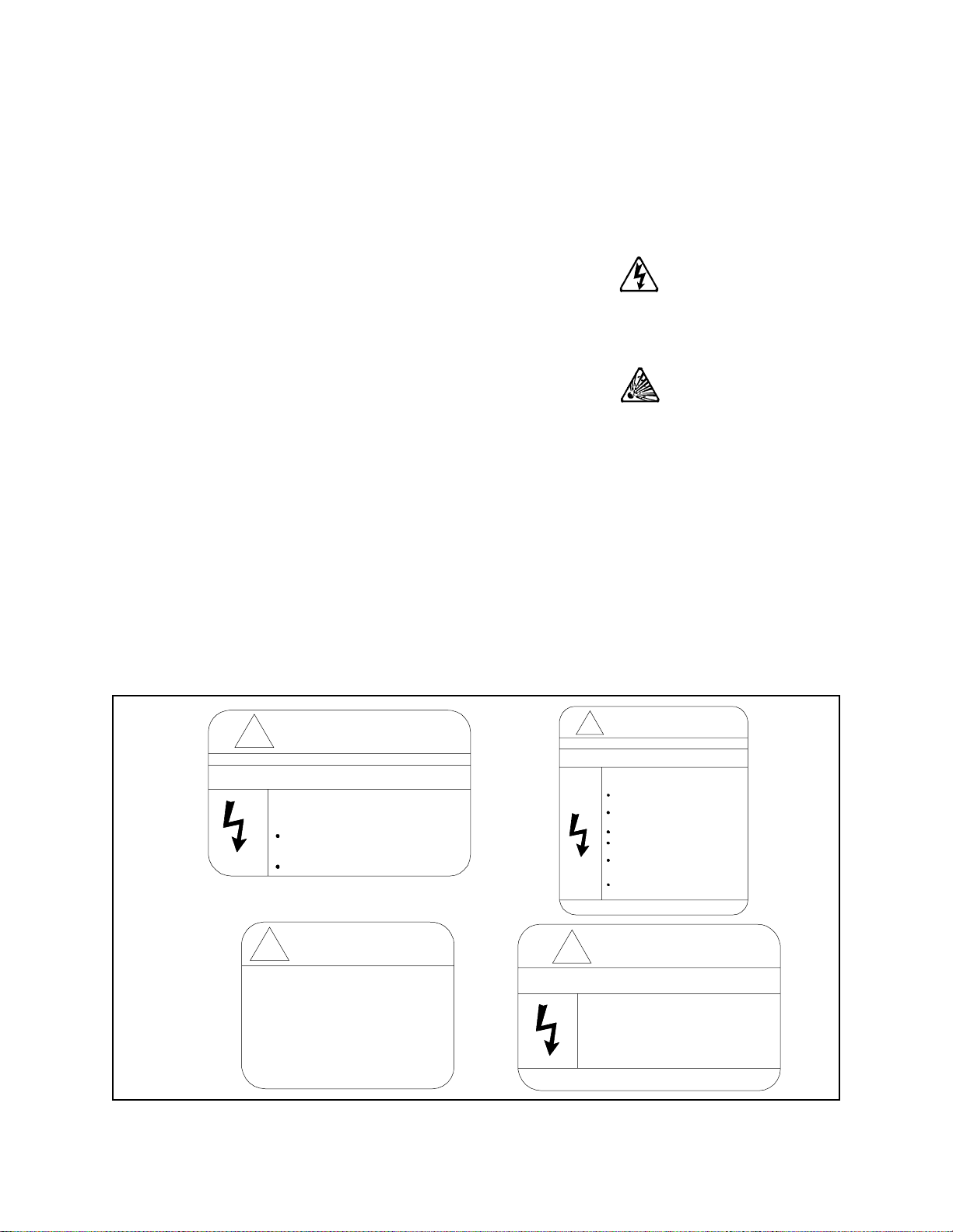
Electrical Hazard Symbol
A symbol which indicates a hazard of injury from electr ical
shock or burn. It is comprised of an equilateral triangle
enclosing a lightning bolt.
Explosion Hazard Symbol
A symbol which indicates a hazard of injury from exploding
parts. It is comprised of an equilateral triangle enclosing an
explosion image.
Equi pment Warning Labels
DO NOT attempt to insta ll, operate, perform maintenance, or dispose of this equipment until you have
read and understood all of the product labe ls and user directions that are contained in this manual.
Shown below are examples of safety labels tha t may be found attached to the equipment. DO NOT
remove or cover any of the labe ls. If the labels are damaged or if a dditional labels are required, contact
your Toshiba sales representative for additional labels.
Labels atta ched to the equipment are there to provide useful information or to indica te an imminently
hazardous s ituation tha t m ay result in serious injury, severe property and equipment damage, or death if
the inst r uctions are not followed.
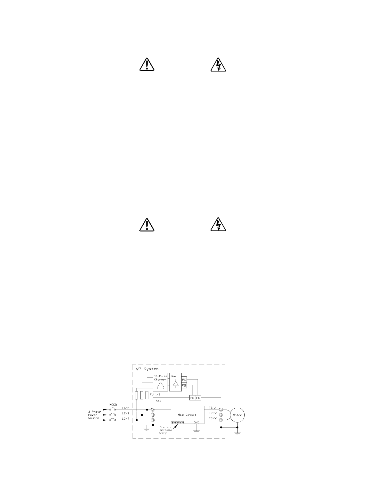
Figure 1. Examples of labels that may be found on the equipment.
DANGER
DANGER
!
DO NOT REMOVE, DESTROY, OR COVER THIS LABEL.
READ THE INSTRUCTION MANUAL CAREFULLY BEFORE
ENTERING THIS COMPARTM ENT.
HAZARDOUS VOLTAGE Behind These Panels.
Contact With Energized Main Bus Will Cause
Severe Injury, Death, Fire, Explosion, Or
Property Damage.
Turn Off And Lockout Primary And
Control Circuit Power Before Opening
These Panels.
Qualified Operators Only.
CAUTION
!
Excessive Loadin g of Operating Shaft
Can Prevent Contact or From Clos in g
Properly Resulti ng In Major Damage.
Do Not Use Contactor Shaft To Drive
Accessories Such As Mechanical Interlocks
Which Require More Than 5 Kgf-cm Of
Torque To Operate.
DO NOT OPEN THIS DOOR WHILE THE UNIT IS RUNNING.
THIS DOOR IS INTERLOCKED WITH ASD OPERATION.
!
DO NOT REMOVE, DESTROY, OR COVER THIS LABEL.
READ THE INSTRUCTION MANUAL CAREFULLY BEFORE
INSTALLING, OPERATING, OR SERVICING THIS EQUIPMENT.
HAZA RD OUS VOLTAGE
Can Cause Severe Injury, Death, Explosion,
Fire, Or Property Damage.
Only Qualified Personnel Should Be Permitted
To Operarate or Service This Equipment.
Disconnect And Lockout Primary And Control
Circuit Power Before Servicing.
Keep All Panels And Covers Securely In Place.
Never Defeat, Modify, Or Bypass Safety
Interlocks.
Foreign Voltage May Be Present At Interface
Terminals. Isolate Before Performing Service
Or Repairs.
Unauthorized Modifications To This Equipment
Will Void The Warranty.
!
DANGER
HAZARDOUS VOLTAGE MAY BE PRESENT.
Capacitors Are Charged. Wait
At Least 5 Minutes Before Entry.
Check For Charged Voltage
To Dissipate To A Safe Level
Before Opening The Equipment.
2 W7 ASD Installation and Operation Manual
Page 9

Qualified Personnel
Installatio n, ope ratio n, and maint enanc e shal l be perfor med by Qualified Personnel Only. A Qualified
Person is one that has the skills and knowledge relating to th e c onstruction, ins tallation, operation, and
maintenance of the el ectrical equi pme nt and has re ceived safety training on the haza rds involved (Re f er
to the latest edition of NFPA 70E for additional safety requirements).
Qualified Personnel shall:
• Have carefully rea d the enti re ope ration manual.
• Be familia r with the construction and function of the ASD, the equipment being driven, and the
hazards involved.
• Able to recognize and properly addr es s hazards associated with the application of motor-driven
equipment.
• Be traine d and au thorized to safely e nergize, de-energize, ground , lockout/tagout circuits and
equipment, and clear faults in accor d ance with es tablish ed safety p r actices.
• Be trained in the proper care and use of protecti ve equipment such as safety shoes, rubber gloves,
hard hats, safety glasses, face shields, flash clothing, etc., in accordance with established safety
practices.
• Be trained in rend ering first aid.
For further information on workplace safety visit www.osha.gov.
Equipment Inspection
• Upon receipt of the equipment inspe ct the packaging and equipment for shipping dama ge.
• Carefully unpack the equipment and check for parts tha t m ay have been damaged during shi pping,
missing par ts, o r conce aled da mage. I f any disc repanc ies a re dis covere d, it should be n oted wit h th e
carrier prior to accepting the shipment, if poss ible. File a claim with the carr ier if necessary and
immediately notify your Toshiba sales representati ve.
• DO NOT install or energize equipment that has been damaged. Damaged equipment may fail
during operation resulting in equipment damage or personal injury.
• Check to see that the rated capacity and the model number specified on the nameplate conform to
the order specifi cations.
• Modification of this equipment is dangerous and must not be performed except by factory trained
representat ives. When modificati ons are re quired contact your Toshiba sales representative .
• Inspections may be required before and after moving installed equipment.
• Keep the equ ipm ent in an upright positi on.
• Contact your Toshiba sales representative to report discrepancies or for assistance if required.
Handling and Storage
• Use prope r lifting te chniques when moving the ASD; including properly sizing up the load, getting
assistance, an d usi ng a forklift if required.
• Sto re in a well-ventilated cover ed locat io n and prefe r ably in the original carton if the equip me n t
will not be used upon receipt.
• Store in a cool, clean, and dry location. Avoid storage locations with extreme temperatures, rapid
temperature ch anges, high humidity, moisture, dust, corrosive gases, or metal particles.
W7 ASD Installation and Operation Manual 3
Page 10

• The storage temperature range of the W7 ASD is 14 to 104° F (-10 to 40° C).
• Do not store the unit in pl aces tha t are e xposed to outside we ather c onditi ons (i. e., wi nd, rain , snow,
etc.).
• Store in an upright position.
Disposal
Never dispose of electrical components via inc ineration. Contact your state environmental agency for
details on disposal of electrical components and packaging in your area.
4 W7 ASD Installation and Operation Manual
Page 11

Installation Precautions
Location and Ambient Requirements
• The Toshiba ASD is intended for permanent installations only .
• Installation should conform to the 2005 National Ele ctrical Code — Article 1 10 (Requirements
For Electric al Insta ll ati o ns ), all regulations of the Occupational Safety and Health
Administration, and any other applicable national, regional, or industry codes and standards.
• Select a mounting location that is easily accessible, has adequate personnel working space, and
adequate il lum ination for adjustment, inspecti on, and maintenance of the equipment (refer to 2005
NEC Article 110-13).
• A noncombustible insulating floor or mat should be provided in the area immediately surrounding
the electrica l system.
• Do Not mount the ASD in a location that would produce catast rophic results if it were t o fall from
its mounting loca tion (equipment damag e or injury).
• Do Not mount the ASD in a locati on that would allow it to be exposed to flammable chemical s or
gasses, water, solvents, or other fluids.
• Avoid installation in areas where vibration, heat, humidity, dust, fibers, metal particles, explosive/
corrosive mists or gases, or sources of electrical noise are present.
• The installation location shall not be expo se d to direct sunlight.
• Allow proper cl earance spaces for installation. Do not obstruct the ventilation openings. Refer to
the section titled
requirements.
• The ambient operating temperature range of the W7 ASD is 14 to 104° F (-10 to 40° C).
• See th e sec ti on titl ed I nst alla tion an d Conne ctio ns on pg. 13 for a dditio nal informati on on i nsta lling
the drive.
Installation and Connections on pg. 13 for further information on ventilation
Mounting Requirements
• Only Qualified Personnel should install this equipm ent.
• Install the unit in a secure and upright position in a well-ventilated area.
• A noncombustible insulating floor or mat should be provided in the area immediately surrounding
the electrica l system at the plac e w h ere maint en ance operations are to be performed.
• As a minimum, the installation of the equipment should conform to the 2005 NEC Article 110
Requirements F or Ele ctric al Ins tal latio ns , OSHA, as we ll as any o the r appli cable nati ona l, reg ional,
or industry codes and standards.
• Installation practices should conform to the la test revision of NFPA 70E Electrical Safety
Requirements for Employee Workplaces.
• It is the responsibility of the pers on installing the ASD or the electrical main tenance personnel to
ensure that the unit is installed into an enclosure that will protect personnel against elect r ic shock.
W7 ASD Installation and Operation Manual 5
Page 12

Conductor Requirements and Grounding
WARNING
• Use sepa rate me tal c ondui ts fo r rout ing the i nput power, output power, a nd cont rol cir cuits a nd e ach
shall have its own ground cable.
• A separate ground cable should be run insi de the conduit with the input power, output power, and
and control circuit s.
• DO NOT connect control terminal strip return marked CC to eart h ground.
• Always ground the unit to prevent electrical shock and to help reduce electrical noise.
• It is the responsibility of the pers on installing the ASD or the electrical main tenance personnel to
provide proper grounding and branch circui t protection in accor danc e with the 2005 NEC and any
applicable local codes.
The Metal Of Conduit Is Not An Acceptable Ground.
Power Connections
DANGER
Contact With Energized Wiring Will Cause Severe Injury Or Death.
• Turn off, lockout, and tagout all power sources before proceeding to connect the power wiring to
the equ ip ment.
• After ensuring that all power sources are turned off and isolated in accordance with esta blished
lockout/ta gout procedures, connect three-phase power source wiri ng of the correct voltage to the
correct input terminals and connect the out put terminals to a motor of the correct voltage and type
for the application (refer to 2005 NEC Article 300 – W iring Methods and Article 310 – Conductors
For General Wiring). Size the branch circuit conductors in accordance with 2005 NEC Table
310.16.
• Adh er e to the recommended conductor sizes listed in the section titled Cable/Terminal
Specifications on pg. 154. If multiple conductors are use d in parallel for the inp ut or output power,
each branch of the parallel set shall have its own conduit and not share its conduit with other
parallel set s (i .e., place U1, V1, and W1 in one conduit and U2, V2, and W2 in anoth er) (refer to
2005 NEC Article 300.20 and Article 310.4). Nat ional and local electrical codes should be
referenced if three or more power conduc tors are run in the same conduit (refer to 2005 NEC
Article 310 adjustment factors).
Note: National and local codes should be referenced when running more than three
conductors in the same conduit.
• Ensure that the 3-phase input power is Not connect ed to the output of the ASD. This will damage
the ASD and may cause injury to personnel.
• Do not insta ll the ASD if it is damaged or if it is missing any component(s).
• Do Not connect resistors ac ross terminals PA – PC or PO – PC. This may cause a fire.
• Ensure the correct phase sequence and the desired direction of motor rotation in the Bypass mode
(if applicable).
• Turn the power on only after attaching and/or securing the front cover.
6 W7 ASD Installation and Operation Manual
Page 13

Protection
• Ensure that primary protect ion exis ts for the input wiring to the equipm ent. This protect ion must be
able to interru pt the available fault current from the power line. The equipm ent may or may not be
equipped with an in put disconnect (option).
• All cable entry openings must be sealed to reduce the risk of entry by vermin and to allow for
maximum cooling efficiency.
• Follow all warnings and precautions and do not exceed equipment ratings.
• If using multiple motors provide separate overload protection for each motor and use V/f control.
• External dynamic braking resis tors must be thermally protected.
• It is the responsibility of the pers on installing the ASD or the electrical main tenance personnel to
setup the Emergency Off brak ing syste m of the ASD. The function of the Emergency Off braking
function is to remove output power from the driv e in the event of an emergency. A supplemental
braking system may also be engaged in the event of an emergency. For further information on
braking systems, see
68.
Note: A supplemental emergency st opping system should be used wit h the ASD. Emergenc y
stopping shou ld not be a task of the ASD alone.
• Follow all warnings and precautions and do not exceed equipment ratings.
DC Injection Brak ing Current on pg. 65 and Dynamic Braking Enable on pg.
W7 ASD Installation and Operation Manual 7
Page 14

Syste m Integr ation Precautions
The following preca utions are provided as general guidelines for the setu p of the ASD within the
system.
• The Toshiba ASD is a general-purpose product. It is a system component only and the system
design should take this into consider ation. Please conta ct your T os hiba sales represent ative for
application-specific information or for training support.
• The Toshiba ASD is part of a larger system and the safe operation of the ASD will depend on
observing certain precautions and performing proper system integration.
• A detailed system analysis and job safe ty analysis should be perform ed by the systems designer
and/or syste ms inte grator be fore the i nstal lati on of t he ASD com ponent. Con tact your Toshiba sales
representat ive for opti ons availability and for applicat ion-specific system integration inf ormation if
required.
Personnel Protection
• Instal lation, operation, and maintenance sha ll be performed by Qualified Personnel Only.
• A thorough understanding of the ASD will be required before the installation, operation, or
maintenance of the ASD.
WARNING
• Rotating machinery and liv e conductors can be hazardous and s hall not come into contact with
humans. Personnel should be protected from all rotating machinery and electrical hazards at all
times.
• Insulat ors , machine guards, and elect r ical safeguards may fail or be defea ted by the purposeful or
inadvertent actions of workers. Insulators, machine guards, and electrical safeguards are to be
inspected (and tested where possible) at installation and periodically after installation for potential
hazardous conditions.
• Do not allow personnel near rotating machinery. Warning signs to this effect shall be posted at or
near the machinery.
• Do not allow personnel near exposed electrical conductors. Human contact with ele ctrical
conductors can be fatal. Warning signs to this effect shall be posted at or near the hazard.
• Personal protection equipment shall be provide d and used to protect employees from any hazards
inherent to system operation.
• Follow all warnings and precautions and do not exceed equipment ratings.
8 W7 ASD Installation and Operation Manual
Page 15

System Setup Requirements
• When using the ASD as an integral part of a large r system, it is the responsibility of the ASD
installer or main tenanc e p er sonnel to ensure t h at there is a f ail-sa f e in place, i.e., an arrangement
designed to switch the system to a safe condition if there is a fault or failure.
• System safety features should be employed and designed into the integrated system in a m anne r
such that s ys te m op e r at io n , ev en in th e ev e nt of sy s te m fa i lu r e, wi ll no t cau s e h arm o r res ul t in
personnel injury or system damage (i.e., E-Off, Auto-Restar t settings, System Interlocks, etc.).
• The programming s etup and system configurat ion of the ASD may allow it to start the moto r
unexpect edly. A familiarity with the Auto-restart and the Remote/Local settings and function is a
requirement to use this product.
• Improperl y desig ned or impr operly inst al led syst em interl ocks may ren der the m otor unabl e to star t
or stop on command.
• The failure of external or ancillary components may cause intermittent system operation (i.e., the
system may sta rt the motor without warning).
• There may be thermal or physical properties, or ancillary devices i ntegrated into the overall system
that may allow for the ASD to start the motor without warning. Signs to this effect must be posted
at the equipment installati on site and near the drive n equipment.
• If a secondary magnetic contactor (MC) is used between the ASD out put and the load, it should be
interlocke d to halt the ASD before the secondary contact opens. If the output contactor is used for
bypass operati on, it must be interlocked such that commercial power is never applied to the ASD
output terminals (U, V, W).
• Power factor improvement capacitors or surge absorbers must not be installed on the output of the
ASD.
• Use of the built-in system protective features is highly recommended (i.e., E-Off, Overload
Protection, etc.).
• The operating controls and system status indicato rs should be clearly readabl e and positioned
where the operator can se e the m wit hout obstruction.
• Additi onal warnings and notifications shall be pos ted at the equipment ins tallation loca tion as
deemed required by Qualified Personnel.
• Follow all warnings and precautions and do not exceed equipment ratings.
W7 ASD Installation and Operation Manual 9
Page 16

Operational and Maintenance Precautions
WARNING
• Turn off, lockout, and tagout the main powe r, the cont rol power, and instrumentation connections
before inspecti ng or servicing the drive, or opening the door of the enclo su r e.
• Turn off, lockout, and tagout the main powe r, the cont rol power, and instrumentation connections
before proceeding to disconnect or connec t the power wiring to the equipment.
• The capac itors of t he ASD mai ntain a resi dual c harge for a pe riod of time after turn ing the ASD off .
The required time for each ASD ty pef orm is indica ted with a cabine t label and a Charge LED.
Wait for at least the minimum time ind icated on the enclosure-mounted label and ensure that the
Charge LED has gone out before opening the door of the ASD once the ASD power has been
turned of f.
• Turn the power on only after attaching (or closing) the front cover and Do Not remove the front
cover of the ASD when the power is on.
• Do Not attempt to disassemble, modify, or repair the ASD. Call your Toshiba sales representative
for repair information.
• Do not place any objects inside of the ASD.
• If the ASD should emit smoke or an unusual odor or sound, turn the power off immediately.
• The heat si nk and other components may become ext remel y hot to the t ouch. All ow the unit to cool
before coming in contact with these items.
• Remove power from the ASD during extended periods of non-use.
• The system should be inspected periodically for damaged or improperly functioning parts,
cleanliness, and to ensure that the connectors are tightened securely.
• Ensure that the Run functions (F, R, Preset Speed, etc.) of the ASD are off before perf ormi ng a
Reset. The post-rese t settings may allow the ASD to start unexpectedly.
• Retry or Reset settings may allow the motor to start unexpectedly. Warnings to this effect sh ould
be clearly poste d near the ASD and the motor.
• In the event of a power failure, the motor may restart after power is restored.
• Follow all warnings and precautions and do not exceed equipment ratings.
DO NOT install, operate, perform maintenance, or dispose of this equipment until you have rea d and
understood all of the product warnings and use r direc tions. Failure to do so may res ult in equipment
damage, operator injury , or loss of life.
Service Life Information
Part Name Service Life Remarks
Large Capacity Electrolytic
Capacitor
Cooling Fan 26,00 0 H o urs
5 Years
When not used for long periods,
charge semi-annually.
CN Connectors 100 Connec ts/Disconne cts
On-board Relays 500,000 Actuations
10 W7 ASD Installation and Operation Manua l
Page 17

Motor Characteristics
Listed below are some va riable speed AC motor contro l conc epts with which the user of the
W7 Adjustable Speed Drive should become familiar.
Pulse Width Modula tio n Op e ration
The W7 ASD uses a sinusoidal Pulse Width Modulation (PWM) control system. The output current
waveform generated by the ASD approaches that of a perfect sin e wa ve; however, the output waveform
is slightly dis torted. For this reason, the motor may produce more heat, nois e, and vibration when
operated by an ASD, rather than directly from commercial power.
Overload Protecti on Adjustment
The W7 ASD sof tware monitors the output current of the system and determines when an overload
condition occ urs . The overload current level is a percentage of the rating of the motor. This function
protects the motor from overload.
The default setting for the overload detection circuit is set to the maximum rated current of the ASD at
the factor y. This sett ing will have to be adjusted to m atch the rat ing of the motor with which the ASD is
to be used. To change the overload re ference level, see
Electro nic Thermal Protection #1 on pg. 70.
Power Factor Correction
DO NOT connect a power factor correction capacitor or surge absorber to the output of the ASD.
If the ASD is used with a motor that is equipped with a capacitor for power factor correction, remove
the capacitor fro m the motor.
Connecting e ither of t hese device s to the out put of the ASD may c ause the ASD to mal func tion an d tri p,
or the output device may cause an over-c urrent condition resu lting in damage to the device or the ASD.
Light Load Conditions
When a motor is operated under a continuous light load (i.e., at a load of less than 50% of its rated
capacity) or it drives a load which produces a very small amount of inertia, it may become unstable and
produce abnormal vibration or trips because of an over-current condition. In such a case , the carrier
frequency may be lowered to compensate for this undesirable condition (see Program
Control
Note: For proper operation, the carrier fre quency must be 2.2 kHz or above except when
⇒
PWM Carrier Frequency).
operating in the Constant Torque or Variable Torque modes.
Load-pro du ce d Nega tiv e Torque
When the ASD is used wi th a loa d that pro duc es negat ive torq ue (an ove rhauli ng loa d), the over -vol ta ge
or over-current protective functions of the ASD may cause nuisance tripping.
⇒
Special
To minimize the undesirable effec ts of nega tive torque the dynami c bra king system may be used. The
dynamic braking system converts the regenerated energy into heat that is dissipated using a braking
W7 ASD Installation and Operation Manual 11
Page 18

resistor. The braking resistor must be s uitably matched to the load. Dyna mi c braking is also e ffective in
reducing the DC bus voltage during a momentary over-voltage condition.
If under extreme conditions t he dynamic braking s ys tem or a component of this system were to fail, the
dynamic braking resistor may experience an exte nded over-current condition. The DBR circuit was
designed to di ssi pate excessive amou nts of heat and if t he extend ed over -curre nt condit ion were al lowed
to exceed the circuit parameters, this condition could result in a fire hazard.
To combat this condition, the 3-phase input may be connected using contactors that are configured to
open in the event of an extended DBR over-current condition or an int ernal circuit failure. Using a
thermal sen sor an d/or overloa d pro tect ion as th e 3- phase input c ont actor driv e sig nal, t he con tact ors wil l
open and remove the 3-phas e input power in the event of an ext ended DBR over -current or sys tem overvoltage condition.
Motor Braking
The motor ma y continue to rotate an d coast to a stop after being shut off due to the in ertia of the load. If
an immediate stop is required, a braking system should be used. The two most common types of motor
braking system s use d with the W7 ASD are DC Inject ion Bra k ing and Dynamic Braking.
For further information on braking systems, see DC Injection Braki n g Current on pg. 65 and
Dynamic Braking Enable on pg. 68.
CAUTION
ASD Characteristics
Over- current Protection
Each W7 ASD model was designed for a specified operating powe r range . T he ASD will incur a trip if
the design specifications are exceeded.
However, the ASD may be operated at 100% of the specified output-current range continuously or at
120% for a limited time as ind icated in the section titled
Also, the Overcurren t Stall Le ve l setting may be adjus ted to help with nuisance over-current trips.
When using the ASD for an a pplication tha t controls a motor which is r ated significantly less than the
maximum current rating of the ASD, the over-c urrent limit (Thermal Overload Protectio n) setting will
have to be changed to match the application. For further information on this parameter, see
Thermal Protection #1 on pg. 70.
ASD Capacity
The W7 ASD must not be used with a motor that has a significantly larger ca pacity, even i f the motor is
operated under a small load. An ASD being used in this way will be susceptible to a high-output peak
current which may result in nuisance tripping.
Do not apply a level of input voltage to an ASD that is beyond that which the ASD is rated. The input
voltage may be stepped down if require d with the use of a step-down transformer or som e other type of
voltage-reduction system.
Current/Voltage Specifications on pg. 155.
Electronic
12 W7 ASD Installation and Operation Manua l
Page 19

Installation and Connections
The W7 Adjustable Speed Drive may be set up initially by performing a few simple configuration
settings. To operate properly, the ASD must be securely mounted and connected to a power source (3phase AC input at the L1/R, L2/S, and L3/T terminals). The control terminals of the ASD may be used
by connecting th e termi nals of the Control Terminal Strip to the proper sensors or signal input sou rces
(see the section titled
The output terminals of the ASD (T1/U, T2/V, and T3/W) must be connected to the motor that is to be
controlled (see
As a minimum, the installation of the ASD shall conform to Article 110 of the 2005 NEC, the
Occupational Safety and Health Administration requirements, and to any other loca l and regional
industry code s a nd st andards.
Installation Notes
When a brake-equipped motor is connected to the ASD, i t is possible that the b r ake may not release at
startup be cause of i nsuf f icie nt vo ltage . To avoid this, Do Not conn ect t h e b rake or t he b ra ke cont ac to r to
the output of the ASD.
If an output cont actor i s used for byp ass opera tion, it mus t be int erlock ed such tha t commer cial po wer is
never applied to the output terminals of the ASD (T1/U, T2/V, or T3/W).
If a secondary magnetic contact or (MC ) is used betwe en the output o f the ASD and the motor, it should
be interlocked such that the ST – CC connection is disconnected before the output cont actor is opened.
I/O and Control on pg. 17).
Figure 17 on pg. 24).
Do Not open and then close a secondary magneti c contactor bet w een the ASD and the m otor unless the
ASD is off and the motor is not rotating.
Note: Re-applicat ion of power via a secondar y contact while the ASD is on or while the
motor is s t il l turnin g m ay cause ASD dam a g e.
On some devices the ST-to-CC connection is further enhanced by the operat ion of the MS1 AUX relay
circuit. The MS 1 AUX relay circuit is normally open and closes the ST-to-CC connection (via ST1)
only after normal system p o w er is available. Th e MS1 AUX relay circuit prohibits the ST-to-CC
connection in the event that the MS1 contactor fails to close during start up or if MS1 opens while the
ASD is running. For the 460 volt ASD this feature is availab le on the 75 HP and above systems.
Figure 2. Alternative ST activation using the MS1 AUX circuit configuration.
The ASD input voltage should remain within 10% of the spec ified input volta ge range. Input voltages
approaching the upper or lower limit settings may require that the overvoltage and undervo ltage stall
protection level parameters be adjusted. Voltages outside of the permissible tolerance should be
avoided.
The frequency of the inp ut power should be ±2 Hz of the specified input frequency.
Do not use an ASD with a motor t hat has a power rating that is higher than the rated output of the ASD.
W7 ASD Installation and Operation Manual 13
Page 20

The ASD is designed to operate NEMA B motors. Consult with your sales representative before using
CAUTION
the ASD for special applica tions such as with an explosion-proof motor or applications with a piston
load.
Do Not apply commercial power to the output terminals T1/U, T2/V, or T3/W.
Disconnect the ASD from the motor before megging or applying a bypa s s voltage to the motor.
Interface problems may occur when an ASD is used in conjunction with some types of process
controllers. Signal isolati on ma y be req uired to prevent controll er and/or ASD malfunction (c ontact
your Toshiba sales repre s entative or the process controller manufacturer for additional informat ion
about compatibility and signal isolation).
Use caution when setting the output fre quency . Over speeding a motor decreases its abilit y to deliver
torque and may result in da ma ge to the motor and/or the driven equipment.
All W7 ASDs are equipped with internal DC bus fuses. However, not all W7 ASDs are equip ped wit h
internal primary power input fuses (HP-dependent).
Mounting the ASD
Install the unit securely in a well ventilated area that is out of direct sunlight using the mounting holes
on the rear of the ASD.
The ambient temperature rating for the W7 ASD is from 14 to 104° F (-10 to 40° C). The process of
converting AC to DC, and then back to AC produces heat. During normal ASD operation, up to 5% of
the inp u t energy to the ASD may be dissipated as heat. If installing t h e A SD in a cabinet, ensur e that
there is adequate ventilation.
Do Not operate the ASD with the enclosure door open or removed.
Note: Ensure that the ventilation ope nings are not obstructed.
ASDs produce high-frequency noise — steps must be ta ken during installation to avoid the negative
effects of noise. Listed below are some examples of measures that will help to combat noise problems.
• Separate the input and output power conductors of the main circuit. Do not instal l the input and
output wires in th e sam e duct or in parallel with each other, and do not bind them to gether.
• Do not insta ll the input or output powe r conductors of the main circuit and the wires of the control
circuit in the sa me duct or in parallel with each other, a nd do not bind them together.
• Use shielded wires or twis te d wires for the control circuits.
• Ensure that the grounding terminals (G/E) of the ASD are securely connected to ground.
14 W7 ASD Installation and Operation Manua l
• Connect a surge suppressor to every electromagnetic contactor and every relay installed nea r the
ASD.
• Install noise f ilters as required.
Page 21
Connecting the ASD
DANGER
Refer to the section titled Installation Precautions on pg. 5 and the section titled Lead Length
Specifications on pg. 16 before attempting to connect the ASD and the motor to electrical power.
System Grounding
Proper grounding helps to prevent elec trical shock and to reduce ele ctrical noise. The ASD is designed
to be grounded in accordance with Article 250 of the 2005 NEC or Section 10/Part One of the
Canadian Electrical Code (CEC).
The grounding condu ctor shall be sized in accordance with Article 250-122 of the 2005 NEC or Part
One-Table
Note: The metal of conduit is not an acceptable ground.
The input power, output power, and control lines of the system shall be run in separate metal co nduits
and each shall have its own ground conductor.
Power Connections
6 of the CEC.
DANGER
Connect the 3-phase input power to the input terminals of the W7 ASD at L1/R, L2/S, and L3/T.
Connect the output term inals T1/U, T2/V, and T3/W of the W7 ASD to the motor.
The input and output conductors and terminal lugs used shall be in accordance with the specifications
listed in the section titled
An inductor may be connecte d ac ross terminals PA and PO to provide additional filtering. When not
used, a j u mper must be connecte d across these terminals (see
Connect the input and output power lines of the W7 ASD as shown in Figure 3.
Install a molded case circ uit breaker (MCCB) or fuse between the 3-phase power source and the W7
ASD in accordance with the fault current setting of the ASD and 2005 NEC Article 430.
Note: In the event that the motor rotates in the wrong direction when powered up, reverse
any two of the three A SD output power leads conn ected to the motor.
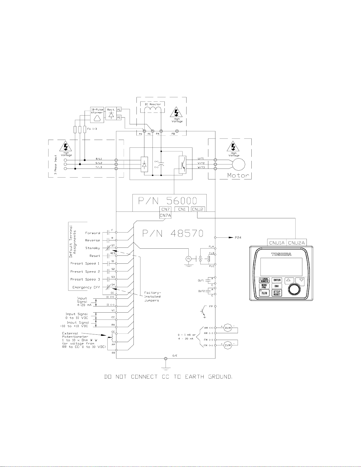
Figure 3. ASD/Motor connection diagram.
Cable/Terminal Specifications on pg. 154.
Figure 17 on pg. 24).
W7 ASD Installation and Operation Manual 15
Page 22

Lead Length Specifications
Adhere to the 2005 NEC and any local codes during the installation of ASD/Motor systems . Ex cessive
lead lengths may advers ely effect the performance of the motor. Special cables ar e not required. Lead
lengths fr om the ASD to the motor in excess of those listed in
the output of the ASD. Tab le 1 lists the suggested maximum lead lengths for the listed motor voltages.
Table 1. Suggeste d max im um le ad lengths.
Table 1 may require filters t o be added to
Model
230 Volt All 1000 feet
460 Volt
600 Volt
Note: Contact Toshiba for application assistance when using lead lengths in exces s of those
listed.
PWM Carrier
Frequency
< 5 kHz 600 feet
≥ 5 kHz 300 feet
< 5 kHz 200 feet
≥ 5 kHz 100 feet
NEMA MG-1-1998 Section IV Part 31
Compliant Motors
2
Exceeding the peak voltage rating or the allowable thermal rise time of the motor
insulation will reduce th e life expect ancy of the motor.
For proper operation, the carrier freq uency must be 2.2 kHz or above except when
operating in the Constant Torque or Variable To rque modes.
Startup and Test
Perform the following checks before turning on the unit:
• L1/R, L2/S, and L3/T are connected to the 3-phase input power.
• T1/U, T2/V, and T3/W are connected to the motor.
• The 3-phase input voltage is within the specified tolerance.
• There are no shorts and all grounds are secured.
16 W7 ASD Installation and Operation Manua l
Page 23

I/O and Control
The W7 ASD can be controlled by several input types and combinations thereof, as well as operate
within a wide range of output frequency and voltage levels. This section describes the ASD control
methods and supported I/O functions.
Control Terminal Strip
The Control Terminal Strip PCBA (P/N 48570) supports discrete and analog I/O functions.
The Control Terminal Strip is shown in F igure 5 on pg. 20. Table 2 and lists the names, the default
settings (where applicable), and the descriptions of the input and output termin als.
Figure 17 on pg. 24 shows the basi c connection diagram for the W7 ASD system.
Table 2. Contro l Terminal Strip default assignment terminal names and functions.
Terminal
Name
ST Discret e Input
RES Discret e Input
F Discret e Input
R Discret e Input
S1 Discret e Input
S2 Discret e Input
S3 Discret e Input
S4 Discret e Input
RR Analog Input
RX Analog Input
II Analog Input
VI Analog Input
P24
PP
OUT1
OUT2
FP Output
AM
FM
FLC
FLB
FLA
CC
Discrete Input Terminals ⇒ On = connected t o CC.
Analog Input terminals reference CC.
Input/Output
DC Output
DC Output
Discrete Output
Discrete Output
Output
Output
Output
Output
Output
—
Standby (jumper t o CC to operate the unit) — Multifunctional
programmable discrete input (see
inform ation on this terminal).
Reset — Multifunct ional progr am mable discrete input.
Forward — Multifunctional programmabl e discrete input.
Reverse — Multifunctional programmable discrete input.
Preset Speed 1 — Multifunctional programm able discrete input.
Preset Speed 2 — Multifunctional programm able discrete input.
Preset Speed 3 — Multifunctional programm able discrete input.
Emergency Off — Multifunctional programmable discrete input.
RR — Multifunction programmable analog input
(0.0 to 10 volt input — 0 to 80 Hz output). Reference CC.
RX — Multifunctional programmable analog input
(-10 to +10 VDC input — -80 to +80 Hz outp ut). Refere n c e C C .
II — Multifuncti onal programmable analog i nput (4 [0] to 20 mADC
input — 0 to 80 Hz output) (see
II termin al). Reference CC.
VI — Multifunctional programmable analog input
(0 to 10 VDC input — 0 to 80 Hz output). Reference CC.
24 VDC @ 50 mA output.
PP — 10.0 VDC volta g e source for the external potentiometer.
Low Frequency — Multifunctional programmable discrete output.
Reach Frequency — Multifunctional programmable discrete output.
Frequency Pulse — an output pulse trai n that has a frequency which is
based on the output frequency of the ASD.
Produces an output current that is pr oportional to the magnit ude of the
function assigned to this terminal (see
Fault re la y (co m m o n) .
Fault re la y (N. C .) .
Fault re la y (N. O .) .
Control common (Do Not connect to Earth Gnd).
Terminal Function
(default setting if programmable)
Installation Notes on pg. 13 for further
Figure 5 on pg. 20 for the location of the
Table 8 on page 142).
Circuit Config.
Figure 7 on pg. 23.
Figure 8 on pg. 23.
Figure 9 on pg. 23.
Figure 10 on pg. 23.
Figure 11 on pg. 23.
Figure 12 on pg. 23.
Figure 13 on pg. 23.
Figure 14 on pg. 23.
Figure 15 on pg. 23
Figure 16 on pg. 23.
W7 ASD Installation and Operation Manual 17
Page 24

I/O Terminal Descriptions
Note: The programmable term inal assignments of the discrete input terminals may be
accessed and changed from their default settings as mapped on
Terminals).
ST — The default setting for this terminal is ST. The function of this input as ST is a Standby mode
controller (system is in St a ndby when on). As the default setting, this terminal must be connected to
CC for normal operation. If not connected to CC, Off is displayed on the LCD screen. This input
terminal may be programmed to any 1 of the 69 functions that are list ed in
Terminal on pg. 128 for more informati on on this terminal.
RES — The default setting for this terminal is RES. The function of this input as RES is a system
Reset. A momentary connection to CC resets the ASD and any fault indicat ions from the display. This
input terminal may be programmed to any 1 of the 69 possible func tions that are liste d in
page 138. Reset is effectiv e when fa u l te d o nly. See RES Terminal on pg. 106 for more information on
this terminal.
F — The default setting for this terminal is Forward Run. Forward Run runs the motor in the
Forward direction when it is on. This input terminal may be programmed to any 1 of the 69 functions
that are li s t ed in
R — The default setting for this terminal is Reve rse Run. Reverse Run runs the motor in the Reverse
direction when it is on. This input terminal may be programmed to any 1 of the 69 functions that are
listed in
S1 — The default setting for this terminal is S1. The function of this input as S1 is to run the motor at
Preset Speed #1 (see
programmed to any 1 of the 69 functions that are lis ted in Table 6 on page 138. See S1 Terminal on pg.
119 for more information on this terminal.
Table 6 on page 138. See R Terminal on pg. 111 for more information on this terminal.
Table 6 on page 138. See F Termina l on pg . 75 for more information on this terminal.
Preset Speed #1 on pg. 100) when it is on. This input terminal may be
pg. 42 (see Input
Table 6 on page 138. See ST
Table 6 on
S2 — The default setting for this terminal is S2. The function of this input as S2 is to run the motor at
Preset Speed #2 (see
programmed to any 1 of the 69 functions that are lis ted in Table 6 on page 138. See S2 Terminal on pg.
120 for more information on this terminal.
S3 — The default setting for this terminal is S3. The function of this input as S3 is to run the motor at
Preset Speed #3 (see
programmed to any 1 of the 69 functions that are lis ted in Table 6 on page 138. See S3 Terminal on pg.
120 for more information on this terminal.
S4 — The default setting for this terminal is Emergency Off (normally close d). The function of this
input as Emergency O ff is to remove power from the output of t he ASD and may apply a supplemental
braking system usi ng the method selected at the Emg Off Mode selection parameter. This input
terminal may be programmed to any 1 of the 69 functi ons that are lis ted in
Terminal on pg. 121 for more informati on on this terminal.
RR — The default function assigned to this termina l is to carry out the Frequency Mode #1 setting.
The RR terminal accepts a 0 – 10 VDC input signal and controls the function as signed to this te rminal.
This inpu t terminal may be programmed to control the speed or torque of the motor. It may also be used
to regulate (li mi t) the speed or torque of the motor. The gain and bias of this terminal may be adjusted
for application-specific suitability. See
information on this terminal.
RX — The RX termina l accepts a ±10 VDC input signa l and c ontrols the function assigned to this
terminal. This inp ut term inal m ay b e progr ammed t o con trol the sp ee d, tor que, or dire ct ion of the mo tor.
It may also be used to regulat e (limit) the speed or torque of the moto r. The gain and bias of this
terminal m ay be adjusted for applicati on- specific suitabili ty. See
pg. 116 for more information on this terminal.
Preset Speed #2 on pg. 100) when it is on. This input terminal may be
Preset Speed #3 on pg. 101) when it is on. This input terminal may be
Table 6 on page 138. See S4
RR Speed Frequency Setpoint #1 on pg. 107 for more
RX Speed Frequency Setpoint #1 on
18 W7 ASD Installation and Operation Manua l
Page 25

II — The func tion of the II input is to receive a 4 – 20 mA input signal that controls a 0 – 80 Hz output.
This input te rminal may be progr ammed to cont rol the spee d or torque of the m otor an d may not be used
when using the VI in put. Also, the gain and bi as of this terminal may be adjusted. See
VI/II Speed
Frequency Setpoint #1 on pg. 134 for more information on this terminal.
VI — The function of the VI input termina l is to receive a 0 – 10 VDC input signal that cont rols a
0 – 80 Hz output. This input te rm inal may be programmed to control the speed or torque of the motor
and may not be used when using the II input. Also, the gain and bias of thi s te rminal may be adjusted.
See
VI/II Speed Frequency Setpoint #1 on pg. 134 for more informat ion on this terminal.
P24 — +24 VDC @ 50 mA power supply for customer us e.
PP — The function of output PP is to provide a 10 VDC output that may be divided using a
potentiome ter. The tapped voltag e is applied to the RR input to provide manual control of the RR
programmed functi on.
OUT1 — The default setting for this output terminal is Damper Command. This output terminal may
be programmed to provide an indication tha t 1 of 60 possible events has taken place. This function may
be used to signal external equipment or to activate the brake. The OUT1 contact is rated at 2A/250
VAC. S ee
OUT1 Terminal on pg. 89 for more information on this terminal.
OUT2 — The default setting f or this output terminal is ACC/DEC Complete. This output terminal
may be program me d to provide an indication t hat 1 of 60 pos si b le events ha s taken place. This functi on
may be u sed to signal ex ternal equipm ent or to acti v ate the brake. The OUT2 contact is rate d at 2A/25 0
VAC. S ee
OUT2 Terminal on pg. 89 for more information on this terminal.
FP — The default function of this output terminal is to output a series of pulse s a t a rat e that is a
function of the output frequency of the ASD. As the output fr equency of the ASD goes up so does the
FP output pulse rate. This term inal may be programmed to provide output pulses at a rate that is a
function of the output frequency or the magnit ude of any 1 of the 31 the functions lis ted in
Table 8 on
page 142. See FP Te rmi nal Assignment on pg. 74 for more information on this terminal.
AM — This output te rm inal produces an outpu t curre nt that is proportiona l to the output frequency of
the ASD or of the magnitude of the fu nction as signed to this terminal. The available assig n ments for
this output terminal are listed in
Table 8 on page 142. See AM Terminal Assignment on pg. 55 for more
information on this terminal.
FM — This output terminal produces an output current that is proportional to the output frequency of
the ASD or of the magnitude of the fu nction as signed to this terminal. The available assig n ments for
this output terminal are listed in
Table 8 on page 142. Se e FM Terminal Assi gnment on pg. 73 for more
information on this terminal.
FLC — FLC is the middle leg of a single-pole double-throw (relay) switch. This FLC contact of the
relay is sw itche d be tween FLB and FLA. This cont act may b e program med to s witch be twe en FLB and
FLA as a function of any 1 of the 60 condition s li sted in
Table 7 on page 141.
FLB — One of two contacts that, under user-defined conditions, connect to FLC (see Figure 4).
FLA — One of two contacts that, under user -defined conditions, connect to FLC (see Figure 4).
Note: The FLA and FLC contacts are rated at 2A/250 VAC. The FLB co ntact is rated at
1A/250 VAC.
CC — Control common (Do Not connect to Earth Gnd).
Figure 4. FLA, FLB, and FLC switching contacts shown in the de-energized state.
Note: The rela y is sh own in the Faulted or
de-energized condition. During
normal system oper ation the relay
connection is FLC-to-FLA.
W7 ASD Installation and Operation Manual 19
Page 26
Figure 5. Control Terminal Strip PCBA.
1
SW1 and SW2 may be switched to
change the full-scale reading of the
AM and FM output terminals. See
the AM Terminal Assignment and
the FM Terminal Assignment
descriptions for further information
on SW1 and SW2.
CN7A
{
0–1 mA 4–20 mA
SW1
{
0–1 mA 4–20 mA
SW2
TB
II Terminals
Shown below are the TB1 in put a nd outpu t t ermina ls of the Control Terminal Strip PCBA.
For further information on these terminals see pg. 17.
RES
20 W7 ASD Installation and Operation Manua l
RRP24
F
ARS1S2S3S4C CA
OUT1 OUT2
Page 27

W7 ASD Control
.
The Control PCBA (P/N 56000) serves as the primary control source for the W7 ASD and receives
input from the
W7 ASD Keypad.
The Control PCBA has been enha nced to support two new functi ons: Multiple Proto col
Communications and the ability to com municate in eith er half- or full-duplex mode s.
Using the optional multiple-protocol communications interface: the ASD-NANOCOM, the Control
PCBA may be configured for the type of co mmunications protocol being received and resp ond
appropriate ly to the sending device. The ASD-NANOCOM connects to the J4 and J5 connectors
(see Figure 6). A jumper PCBA (P/N 5536 5) is required at the J4 connecto r if not us ing the ASDNANOCOM.
Control Terminal Strip PCBA, an Option Card, RS232/ RS 485 Communication s, or the
The ASD-NANOCOM must be setup to support the desired communications protocol via Program
Comm Settings. Consult the ASD-NANOCOM User’s Manual (P/N 10572-1 .000-000) for a comple te
listing of the setup requirements.
Half or Full duplex com mun ications is available when using RS232/RS 485 com m unications. The
jumpers at the JP1 and the JP2 connectors may be moved from one position to the other to facilitate
either half- or ful l-duplex operation. If no jumpers are used the system will operate in the full duple x
mode.
For more information on the W7 ASD communica tion requirements, please visit
WWW.TIC.TOSHIBA.COM to acqui re a copy of the 7-Series Communications User Manual
(see Literature
the ASD-NANO COM User Manual.
Contact your Toshiba representative if more informat ion is required on the ASD-NANOCOM.
Figure 6. Control Board of the W7 ASD (P/N 56000).
Common Serial (TTL) I/O
(CNU2).
RS232/RS485 signal I/O
(CN3).
⇒
⇒
Manuals ⇒ Drives Manuals) and WWW.ICCDESIGNS.COM to acquire a copy of
CNU8
CN2
CNU3
RS232/RS485 signal I/O
(CNU1).
CNU4
JP1 Jumpers — Half-/Full-Dup lex selection.
W7 ASD Installation and Operation Manual 21
ASD-NANOCOM.
25-pin D-type connector
Connects to the Control
Terminal Strip PCBA (CN7).
Page 28

CNU1/1A and CNU2/2A Pinout
Control Boar d CNU1/1A and CNU2/2A pinout (RJ-45 connectors).
Pin #
1 P24 P24 1
2 Gnd Gnd 2
3 Tx (-) RXA 3
4 Rx (+) TXA 4
5 Rx (-) TXB 5
6 Tx (+) RXB 6
7 RS232/RS485 CNU3 Pin-7 7
8 Gnd Gnd 8
CNU1 Pinout
(Controller PCBA)
CNU1A Pinout
(EOI)
CN3 Pinout
CN3 of the Control Board is u sed for RS232/RS485 serial com munications.
Pin Number
1 RS232/RS485 Signal +
2 RS232/RS485 Signal 3 RS232/RS485 Signal Gnd
4 Shield
Pin #
CN3 Pinout
(Controller PCBA)
CNU2 Pinout
(Controller PCBA)
CNU2A Pinout
(EOI)
P24 P24
Gnd Gnd
Rx Tx
Gnd Gnd
Tx Rx
Gnd Gnd
Open Open
Gnd Gnd
CN7 Pinout
CN7 of the Control Board connec ts to CN7A of the Control Terminal Strip PCBA.
Table 3. CN7 pinout assignments. Programmabl e terminals are liste d as their default settings.
Pin Number Function Pin Number Function
1 PP 14 II
2 FL 15 S1
3 VI 16 R
4 RR 17 S3
5 FM 18 S2
6 RX 19 N15
7 FP 20 S4
8 AM 21 P15
9 *OUT1 22 P24
10 *OUT2 23 CC
11 ST 24 CC
12 RES 25 CC
13 F — —
Note: * Open collector output s.
22 W7 ASD Installation and Operation Manua l
Page 29
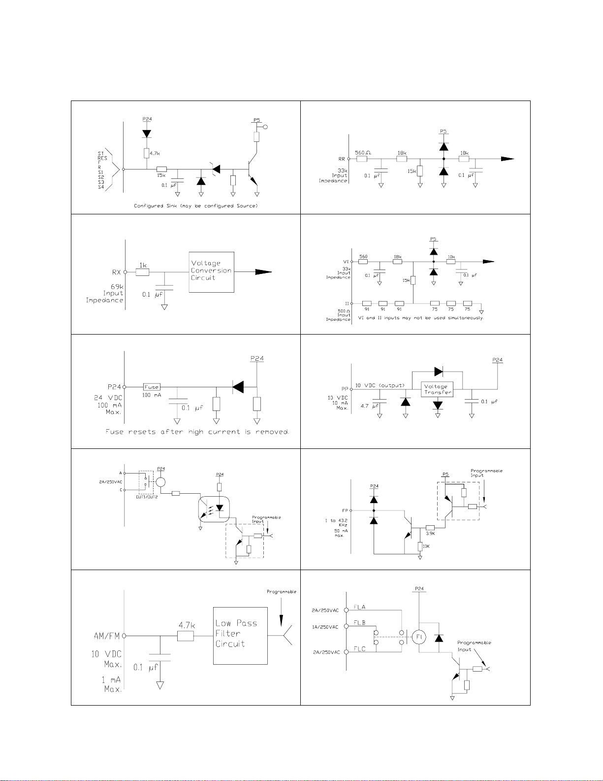
I/O Circuit Configurations
Figure 7. Discrete Input. Figure 8. RR Input.
Figure 9. RX Input. Figure 10. VI/II Input.
Figure 11. P24 Output. Figure 12. PP Output.
Figure 13. OUT1 /OUT2 O u tp ut. Figure 14. FP Output.
Figure 15. AM/FM Output. Figure 16. Fault Relay (active fault).
W7 ASD Installation and Operation Manual 23
Page 30
Typical Connection Diagram
Figure 17. W7 ASD typical connection diagram.
Note: When connecting multi ple wire s to th e PA, PB, P C, or PO termi nals, do not con nect a
solid wire and a stranded wire to the same terminal.
24 W7 ASD Installation and Operation Manua l
Page 31

Electronic Ope rat or In terf ace
The W7 ASD Electronic Operator Interface (EOI ) is comprised of an LCD display, two LEDs, a rotary
encoder, and eight keys. These items are described bel ow and their locations are provided in
Figure 18 on pg. 26.
The EOI can be mounted r emotely f r om the ASD as described in the section titled EOI Remote Mounting
on pg. 27. The dimensional require ments for remote mounting may also be found there. Using a screw
length that excee ds the specified dimensions may cause deformation of the outer surface of the bezel as
shown in
The interface ca n operate up to distances of 15 feet from the ASD vi a the Common Serial (TTL) Port. For
distances beyond 15 feet, the RS232/RS485 port is recommended.
EOI Features
LCD Display — Displays configuration information, performance data (e.g., motor frequency, bus
voltage, output power, etc.), and diagnostic information.
Local|Remote Key — Toggles the system to and from the Local and Remote modes. The LED is on
when the system is in the Local Command m ode. The Local|Remote Key may be switched between the
Local and Remote modes while at the Frequency Command screen only.
The Local Command mod e en ables the Command and Frequency control functions to be carried out
via the EOI.
The Remote mode enables the Command and Frequency contr ol functions to be carried out via any
one of the following methods:
Figure 21 on pg. 29 and should be avoided.
• Pulse Input ,
•Motorized Pot,
• Communication Card,
• RS232/RS485,
• Common TTL,
• Binary/BCD,
• LED Keypad,
• Option Card RX2,
•RX,
•RR, or
• VI/II.
The input channel selection may be made via Program
Settings.
Enter Key — Selects a menu item to be chan ged or accepts an d re cords the changed data of the selected
field (same as pressing the Rotary Encoder).
Esc Key — Returns to the previous level of the menu tree, toggles between the Communication
Command and the Frequency Com m and screens, or cancels changes made to a field if pressed while
still in the rev erse video mode (dark background/light text). The 3 functions are menu-specific.
Run Key — Issues t h e Run command while in th e Local mode. A Run command issued from the EOI
while in the Remote mode will be activated once the Local mode is selected and the m o tor wil l run at the
commanded speed.
Run Key Status LED — Illuminates green while stopped or red while running.
⇒
Utilities
⇒
Command and Frequency
Stop Key — If pressed once while in the Local mode issues the Off command and decelerates the motor
at the programmed rate until it stops. If pressed twice in rapid succession ini tiates an Emergency Off
(terminates th e ASD output and applies the brake if so con figured) from the Local or Remote modes.
W7 ASD Installation and Operation Manual 25
Page 32

Up Key — Increases the value of the selected parameter or scrolls up the menu listing (continues during
press-and-hold).
Down Key — Decreases the value of the selected parameter or scrolls down the menu listing (continues
during press-and-hol d).
Rotary Encoder — Functions as the Up key, the Down key, and the Enter key. Turn the Rotary
Encoder eith er clockw ise or countercl o ckwise to perform the Up or Down key functions. Press the
Rotary Encoder to perform the Enter func tion.
MON/PRG Ke y (Monit o r/ Pr o g r am) — Pr o vi d es a means to access the th r ee ro o t me nu s. Pressi n g the
MON/PRG ke y repeatedly loops the system through the three root menus (see
Figure 24 on pg. 32).
While looping through the root menus, the Program menu will display the last me nu s creen or sub-menu
item b ei ng ac ce s sed at the tim e tha t th e MON/PRG k ey was pre sse d.
Figure 18. The W7 ASD Electronic Operator Interface.
LCD Display
Enter Key
Local/Remote
Key (LED)
Monitor/Program
Key
Run Key
(LED)
Up/Down Arrow
Keys
Rotary Encoder
Esc Key
Stop|Reset Key
EOI Operation
The EOI is the primary input/output devic e for the user. The EOI may be used to monitor system
functions, in put data into the system, or perform diagnostics.
Note: The Up/Down arrow keys and the Enter key may be used to perfor m the funct ions of the
Rotary Encoder. The Rotar y En coder will be use d in this explanation and throughout
this manual for the Up, Down, and Enter key functions.
The software used with the W7 ASD is menu driven; thus, making it a select and click environme nt. The
operating parameters of a motor may be selected and viewed or changed using the EOI.
To change a parameter setting, go to the Program mode by pressing the MON/PRG key until the
Program menu is d is played. Turn the Rota ry Encode r until the desired parameter group is within the
cursor block. Press the Rotary Encoder (repeat if there is a submenu).
The selection will take on the reverse video format (dark background/light text). Turn the Rotary
Encoder to change the value of the parameter. Press the Esc key while the display is in the reverse video
mode to exit the menu without saving the change or pr es s the Rotary Enco der to accept the new setting.
Repeated Esc key entries takes the menu back one level each time the Esc key is pressed until the root
level is reached. After reac hing the root l evel, continu ed Esc entr ies wil l toggle the syst em to an d fr om the
Frequency Command screen and the Communication Co mmand screen.
Note: Panel menu changes enter ed he re will affect EOI-controlled ASD operati on only.
26 W7 ASD Installation and Operation Manua l
Page 33

EOI Remote Mounting
The W7 A SD may be controlled from a remotely-mounted EOI. For safety and application-specific
reasons, some ASD instal lations will warrant that the operator not be in the vicinity during ope ration or
that the EOI not be attached to the ASD housing. The EOI may be mounted ei ther with or without the
optional W7 ASD Remote Mounting Kit (P/N ASD-MTG-KIT). The ease of installation is enhanced by
the W7 ASD Remote Mounting Kit which al lows for easier cable routing and EOI placement.
The EOI can operate up to distances of 15 feet from the ASD via the Common Serial (TTL) Port . For
distances beyond 15 feet, the RS232/RS485 port is recommended.
Remote mounti ng will also allow for m ultiple EOI mount ings at one location if controlling and
monitoring several AS Ds from a central location is required.
The optional dust cov er (P/N AS D-BP C) may be us ed to cover the front panel openi ng of the ASD
housing after removi ng the EOI. A n EOI extender cable is required for remote mounting. EOI extender
cables are availa ble in lengths of 7, 10, or 15 feet and may be ordered through your sales represent ative.
Remote EOI Required Hardware
EOI Mounting Hardware
• 6-32 x 5/16” Pan Head Screw — P/N 50595 (4 ea.)
• #6 Split-Lock Washer — P/N 01884 (4 ea.)
• #6 Flat Washer — P/N 01885 (4 ea.)
Bezel Plate Mounting Hardware
• Bezel Plate — P/N 52291
• 10-32 Hex Nut — P/N 01922 (4 ea.)
• #10 Split-Lock Wa sher — P/N 01923 (4 ea.)
• #10 Flat Washer — P/N 01924 (4 ea.)
• Dust Cover — P/N ASD-BPC (Optional)
Extender Cables
• ASD-CAB7F: Cable, RJ45, 7 ft.
• ASD-CAB10F: Cable, RJ45, 10 ft.
• ASD-CAB15F: Cable, RJ45, 15 ft.
W7 ASD Installation and Operation Manual 27
Page 34

EOI Installation Precautions
Install the unit secu rely in a well ven til ated a rea tha t is o ut of direc t sunl igh t using the four m ount ing holes
of the EOI. The ambient temperature rating for the EOI is 14 to 104° F (-10 to 40° C).
• Select a mounti n g lo cation that is easily access i ble by the user.
• Avoid installation in areas where vibration, heat, humidity, dust, metal particles , or high levels of
electrical nois e (EMI) are present.
• Do not install the EOI where it may be exposed t o flammable chemicals or gasses, water, solvents, or
other fluids.
• Turn the power on only after securing the front cover to the ASD.
EOI Remote Mounting w/o the ASD-MTG-KIT
Note: See Figure 19 for the dimensions and the item location s referenced in s teps 1 through 5.
1. At the EOI mounting location, identify and mark the location of the 3.80” by 3.29” hole and the
7/32” screw holes.
2. Cut the 3.80” by 3.29” rectangular hole.
3. Drill the four 0.22” screw hol es.
4. Attach and secure the EOI to the front side of the mounting location usi ng the four 6-32 x 5/16”
pan head screws, the #6 flat washers, and the #6 split lock washers.
5. Connect the RJ -45 extension cable( s).
EOI Dimensions (mounting)
Figure 19. EOI Mounting Dimensions.
28 W7 ASD Installation and Operation Manua l
Page 35

EOI Remote Mounting using the ASD-MTG-KIT
C
a
e
t
Note: See Figures 20 and 21 for the dimensions and the item locations referenced in steps 1
through 6.
1. At the EOI mounting location, identify and mark the locations of the 5.00” by 4.60” hole and the
four 11/32” screw holes.
2. Cut the 5.00” by 4.60” rectangular hole.
3. Drill the four 11/32” holes.
4. Attach and secure the Bezel plate to the front side of the mounting loca tion using the four 10-32
hex nuts, #10 split lock washers, and the #10 flat washers.
5. Attach and secure the EOI to the front s ide of the Bezel plate using the four 6-32 x 5/16” pan head
screws, the #6 flat washers, and the #6 split lock washers.
6. Connect the RJ -45 extension cable( s).
EOI ASD-MTG-KIT Dime ns ions (mounting)
Figure 20. EOI Bezel Plate Mounting Dimensions.
Mounting Hole
5.00
4.25
11/32" Screw Hole (4)
5.38
Bezel Plate Bezel Plate
4.60
Front View Side View Back View
Figure 21. Screw Length Precaution.
AUTION: Failure to use the correct hardware may result in damage to the outer surface of the EOI panel
nd/or improper seating of the panel to the bezel plate. Use caution when moun ting the EO I assem bly to ensur
hat the internal thread clearance is maintained.
Correct Incorrect
W7 ASD Installation and Operation Manual 29
Page 36

System Operation
Operation (Local)
Read and understand all safet y warnings be fore operating this equipmen t!
To run the motor perform the following steps:
1. Press the MON/PROG key until the Frequency Command screen is displayed (see Figure 24 on
pg. 32).
2. Place the system in the Local mode (green Local LED illuminated) by pressing the Local|Remote
key.
3. Ensure that there are no personnel around or near the motor or the motor-driven equipment.
4. Using the Rotary Encoder dial in a speed setting at the Set field and press the Rotary Encoder.
5. Press the Run key (illuminated green RUN LED turns re d ) an d th e mo to r ac celerat es to th e set
speed at the (default) programmed rate. The spee d may be changed while running.
6. Press the Stop|Reset key to stop the motor.
Default Settin g Chang es
To change a parameter setting using the EOI, press the MON/PRG key until the Program menu is
displayed.
From the Program menu scroll to the desired parameter group and press the Rotary Encoder —
Repeat for sub-m enu ite ms. Once rea ching t he lowest lev el of a parame ter group, s croll t o the par ameter
to be changed and press the Rot a ry Encode r.
The parameter takes on th e reverse vi deo format (dark background /li ght text ). Use the Rotary Encoder
to scroll to the new value or setting. Press the ESC key to exit without saving the parameter change
while still in the reverse video mode or press the Rotary Encoder to accept and save the change.
For a complete listing of the Program menu items, see the section titled Program Menu Navigation on
pg. 35. The menu items are mapped for convenience. The Direct Access Numbers are listed w h ere
applicable. The Direct Access numbers are also listed chronologically in the section titled W7 ASD
Direct Access/Communication Numbers on pg. 46.
The default settings may also be changed by enteri ng the Parameter Number of the setting to be
changed at the Direct Access menu (Program
listing of all parameters that have been changed from the default setting may be viewed s equentially by
accessing the Changed From Default screen (Program
Note: Parameter 009 was changed to create the example shown in Figure 22.
Figure 22. Changed From Default screen.
⇒
Direct Access ⇒ Applicable Parameter Number). A
⇒
Changed From Default).
30 W7 ASD Installation and Operation Manua l
Page 37

The Changed From Default feature allows the user to view (or change) the parameters that are
different from the default or the post-res et settings. Once the Changed From Default scr een is
displayed, the system scrolls through all of the system parameters and halts once reaching a changed
parameter.
The Rotary Encoder may be clicked once clockwise to continue scrolling forward or clicked once
counterclockwise to begin s crolling in reverse. With each click of the Rotary Encoder from a stop, the
system scrolls through the paramet ers and s tops at the next parameter that has been changed.
Pressing the Rotary Encoder whil e a ch an g e d p ar ameter is d isp l ay ed accesses the setti n g s of th e
changed parameter for viewing or changing.
Pressing ESC while the system is performing a Ch an ged From Default sear ch termina t es the search.
Pressing ESC when done searching (or halted at a changed parameter) returns the system to the
Program menu.
Parameter setti ngs may also be ch anged via Communications. See the 7-Series Serial
Communications Manual (P/N 53840) for further information on using communica tions to change
parameter settings. The 7-Series Serial Communications Manual may be acquired from the
TIC.Toshiba.com website at Literature
⇒
Manuals ⇒ Drives Manuals or from your Toshiba Sales
Representative.
W7 ASD Installation and Operation Manual 31
Page 38

System Configuration and Menu Options
s
n
Root Menus
The MON/PRG key is used to access the three root menus of the W7 ASD: the Frequency Command
screen, the Monitor screen, and th e Program screen. From either mode, press the MON/PRG key to
loop through to the other modes (see
In the event of a fault, the W7 ASD displays the fault screen until the source of the fault is removed and
the ASD is reset.
Figure 23. Root Menu Mapp ing.
Figure 23).
Frequency Command Screen
Frequency Setting
While operati ng in th e Local mode ( Local LED is illum inate d on the EOI), t he r unnin g freque ncy of th e
motor may be set from the Frequency Command screen. Using the Rotary Encoder, enter the desired
Frequency Command value, press the Enter key and then press t he Run key. The motor will run a t t he
Frequency Command speed and may be changed while running.
Figure 24. Frequency Command Screen.
Commanded speed in the
Local Mode.
Running speed.
User-selectable unit of
measurement (see User
Unit #1 on pg. 133).
Operating Mode.
{
{
{
{
User-selectable
monitored item
(see Monitor Scree
}
on pg. 33).
Discrete terminal
status — Reverse
}
video if active.
32 W7 ASD Installation and Operation Manua l
Page 39

Monitor Screen
The Monitor screen reports the status of motor performance variables, control settings, and
configuration data during motor operation. There are 30 items th at may be monitored from this mode.
The items are listed and described below.
Up to four of the underlined monitored items listed below may be displayed at the Frequency
Command screen while the ASD is running. See Program
Monitor Selection to select the monitored items to be displayed.
Note: The Monitor screen lists the read-only status of the li sted parameters.
Trip Hold Frequency — If tripped, this field records the at-trip frequency. Otherwise, the current
output frequency is dis played.
Past Trip #4 — This feature reads and stores trip record s and is the fi r st of four recorded trips.
Past Trip #3 — This featur e reads and stores trip rec o r d s.
Past Trip #2 — This featur e reads and stores trip rec o r d s.
Past Trip #1 — This feature reads and stores trip records and is the last of four recorded trips.
Trip Code — If tripped, this field displays the trip code (e.g., E-Stop). If not tripped No Error is
displayed.
AM Output — Displays the AM output as a percentage of its f ull range.
FM Output — Displays the FM output as a percentage of its full range.
⇒
System Information and Setup ⇒
RX2 Input — Displays the RX2 input as a perce ntage of its full range.
RX Input — Displays the RX input as a percentage of its full range.
*VI/II Input — Displays the VI/II input as a percentage of the full range of the VI/II value.
Note: The VI/II input r epres ents two analog i nput s (and termi nal s). The VI input terminal is
used for a 0 – 10 VDC ana log sig nal an d the II input terminal is used for cur rent l oop
applications, such as with a 4-20 mA signal. Either may be used as a frequency or
torque command source; however, the two cannot function simultane ous ly.
Throughout this manual they will be listed as VI/II.
RR Input — Displays the RR input as a percentage of its full range.
Direction — Displays the Forward/Reverse sta tus.
Peak Current — Shows the highest c urre nt le vel ac hieve d sinc e the last star tup o r re set. Th is va lue is
displayed as a percentage of the full rating of the ASD or as an amperage (se e
Current on pg. 133).
Kilowatt Hours — Displays accumulated Kilowatt hours . Saved at 2-hour interval s.
Output Power — Shows the instantaneous output power level of the ASD.
Input Power — Shows the instantaneous input power level to the ASD.
ASD Load — Shows the instantaneous load plac ed on the ASD.
Motor Load — Shows the instantaneous motor load requirements.
Units for Voltage and
ASD Overload Ratio — Displays the relationship of time to the magnitude of the ASD overload as a
ratio. A higher overload means a shorter run-time in this condition.
Motor Overload Ratio — Displays the relationship of time to the magnitude of the motor overload
as a ratio. A higher overload means a shorter run-time in thi s condition.
W7 ASD Installation and Operation Manual 33
Page 40

PID Feedback — Displays the instantaneous PID feedback value.
Post Compensation Frequency — Displays the out put freque ncy of the ASD after the applic ation of
the waveform adjustment compensation for changes in the input voltage.
Run Time — Displays the accumulated run-time since the last reset or power up of the ASD.
Output Terminals — Shows the activ e dis crete output terminals.
Input Terminals — Shows the active discret e input terminals.
Output Vo ltag e — Shows the instantaneous output voltage as a percentage of the rating of the ASD
or as a voltage (s ee
DC Voltage — Shows the instantaneous DC bus voltage as a percentage of the rat ing of the ASD or
as a voltage (see
Output Current — Shows the instantaneous output current as a percentage of the ra ting of the ASD
or as a current (see
Frequency Command — Displays the current frequency command.
Units f o r Voltage and Cur rent on pg. 13 3 ).
Units for Voltage and Current on pg. 133).
Units for Voltage and Current on pg. 133).
Program Screen
The Program Menu allows the user ac ce ss to parameters tha t s etup the input and output specifications
of the W7 ASD. Many of these settings are application-specific and will require setup. The Setup
screen provides easy-access to the most common setup parameters. See the section titled
Navigation on pg. 35 for a complete listing of the W7 ASD parameters and for menu navigation
assistance.
Program Menu
34 W7 ASD Installation and Operation Manua l
Page 41

Program Menu Navig a tion
Table 4 lists the menu items of the Program mode and maps the flow of the menu selections. The
Parame ter Numb ers for the listed functions are provided wher e ap plicable. The functions listed may be
accessed (and change d) as m apped below or via the Direct Access method: Program
Applicable Param eter Number.
Table 4. Progr a m mode mapping.
Program Menu Navigation
⇒
Direct Access ⇒
Primary Menu Sub Menu Parameter Name
FUNDAMENTAL
PARAMETERS
Fundamental #1
Fundamental #2
SYSTEM INFORMATION
AND SETUP
Setup
Maximum Output Frequency 0011
#1 Base Frequency 0014
Suppl y Voltage Compe n sa ti on 0307
Maximum Outp ut Voltage #1 0306
Disable Fo rw ard/Reverse Run 0311
Upper Limit Frequency 0012
Lower Limit Frequenc y 0013
V/f Pattern 0015
Torque Boost #1 0016
Acceleration Time #1 0009
Deceleration Time #1 0010
Acceleration/Deceleration Pattern #1 0502
S-Pattern Lower Li m it Adjustment 0506
S-Pattern Upp er Limit Adjustm ent 0507
Base Frequency #2 0170
Maximum Voltage #2 0171
Torque Boost #2 0172
Thermal Protection #2 0173
Acceleration Time #2 0500
Deceleration Time #2 0501
Acceleration/Deceleration Pattern #2 0503
Acceleration/Deceleration #1/#2 Switching
Frequency
Acceleration Time #1 0009
Deceleration Time #1 0010
Upper Limit Frequency 0012
Lower Limit Frequenc y 0013
VI/II Speed Reference Setpoint #1 0201
VI/II Speed Frequency Setp oint #1 0202
VI/II Speed Reference Setpoint #2 0203
VI/II Speed Frequency Setp oint #2 0204
Type Reset 0007
V/f Pattern 0015
Parameter
Number
0505
W7 ASD Installati on and Operati on Manual 35
Page 42

Program Menu Navigation
Primary Menu Sub Menu Parameter Name
SYSTEM INFORMATION
AND SETUP
Setup
PID Setup
Trip History
(RTC option required)
Switch-on-the-Fly 0961
Electronic Thermal Protection #1 0600
Input Feedback Selection 0360
Delay Filter 0361
Proportional Gain 0362
Integral Gain 0363
Upper Deviat ion Limit 0364
Lower Deviation Limit 0365
Differential Gain 0366
Upper Limit Frequency 0012
Lower Limit Frequenc y 0013
Acceleration Time #1 0009
Deceleration Time #1 0010
Low-output D isable Selection 0731
Low-output D isable Start Level 0732
Low-output D isable Delay Time 0733
Low-output Disable Boost Level 0734
Low-output D isable Boost Time 0735
Low-output D isable Feedba ck Level 0736
Low-output D isable Restart Delay 0737
4–20 mA Loss Selec tion 0962
4–20 mA Speed Refer ence 0964
Frequency Command Panel N/A
PID Feedback Value N/A
Trip Number
Trip Type
Frequency at trip
Outpu t cu rrent
Output voltage
Direction
Frequency reference
DC voltage
Run timer
Post-compensation frequency
Speed feedback (real)
Speed feedback (filtered)
Torque feedback
Torque reference
Torque current
Excitation current
Parameter
Number
N/A
36 W7 ASD Installation and O peration Manual
Page 43

Program Menu Navigation
Primary Menu Sub Menu Parameter Name
SYSTEM INFORMATION
AND SETUP
Trip History
(RTC option required)
Monitor Selection
Password Control
Local/Remote Setup
Contrast
CHANGED FROM DEFAULT
DIRECT ACCESS
UTILITIES
Version
Display Attributes
PID feedback value
Motor overload rati o
ASD overload ratio
DBR overload ratio
Motor load
ASD load
DBR load
Input power
Output power
Peak output current
Peak DC voltage
PG speed
PG position
Monitor #1 (User-selectable)
Monitor #2 (User-selectable)
Monitor #3 (User-selectable)
Monitor #4 (User-selectable)
Enter Pa s sw o rd
Change Password
Command
Frequency
Up/Down Arrow Key 716
(See the section ti tled Default Setting Changes
on pg. 30.)
Parameter Number Input
Enable/Disable Unknown Num bers
CPU Version
CPU Revision Level
Main Board EEPROM Version
ASD Type
EOI Version
Panel Operation Inhibit Selection 0730
Hz per User-defined Unit 0702
Frequency Display Resolution 0703
Acc/Dec Special Display Resolution 0704
Units fo r Voltage and Current 0701
User-defined U n it Charac ter 1 0965
User-defined U n it Charac ter 2 0966
User-defined U n it Charac ter 3 0967
Parameter
Number
N/A
N/A
N/A
N/A
N/A
N/A
N/A
W7 ASD Installati on and Operati on Manual 37
Page 44

Program Menu Navigation
Primary Menu Sub Menu Parameter Name
UTILITIES
FREQUENCY SETTINGS
Display Attributes
Type Reset
Command and
Frequency Settings
Speed Reference
Setpoints
User-defined U n it Charac ter 4 0968
User-defined U n it Charac ter 5 0969
Auto Setup for 50 Hz Operation
Auto Setup for 60 Hz Operation
Restore Factory Defaults
Clear Past Trips
Clear Run Timer
New Base Drive Board
Save User Param eters
Restore U s er Sett ings
Upgrade Firmware
Set EOI Memory to Default
Comm a nd Mode Se lectio n 0003
Frequency Mode #1 Selection 0004
PWM Carrier Fre quency 0300
VI/II Speed Reference Setpoint #1 0201
VI/II Speed Frequency Setp oint #1 0202
VI/II Speed Reference Setpoint #2 0203
VI/II Speed Frequency Setp oint #2 0204
RR Speed Reference Setpoint #1 0210
RR Speed Frequency Setpoint #1 0211
RR Speed Reference Setpoint #2 0212
RR Speed Frequency Setpoint #2 0213
RX Speed Reference Setpoint #1 0216
RX Speed Freque ncy Setpoint #1 0217
RX Speed Reference Setpoint #2 0218
RX Speed Freque ncy Setpoint #2 0219
RX2 Speed Reference Setpoint #1 0222
RX2 Speed Frequency Setpoint #1 0223
RX2 Speed Reference Setpoint #2 0224
RX2 Speed Frequency Setpoint #2 0225
RX2 Torque Refer ence Setpoint #1 0226
RX2 Torque Refer ence Setpoint #2 0227
BIN Speed Reference Setpoint #1 0228
BIN Speed Frequ ency Setpoint #1 0229
BIN Speed Reference Setpoint #2 0230
BIN Speed Frequ ency Setpoint #2 0231
PG Speed Reference Setpoint #1 0234
PG Speed Freque ncy Setpoint #1 0235
PG Speed Reference Setpoint #2 0236
PG Speed Freque ncy Setpoint #2 0237
Parameter
Number
0007
38 W7 ASD Installation and O peration Manual
Page 45

Program Menu Navigation
Primary Menu Sub Menu Parameter Name
FREQUENCY SETTINGS
Reference Priority
Reference Priority Selection 0200
Frequency Mode #2 0207
Reference Priority Mode #1/#2 Switching Frequency 0208
Jog Operation
MOTOR SETTINGS
COMMUNICATIONS SETTINGS
Jog Run Frequency 0260
Jog Stop Control 0261
Base Frequency #1 0014
Maximum Outp ut Voltage #1 0306
Torque Boost #1 0016
Electronic Thermal Protection #1 0600
Base Frequency #2 0170
Maximum Outp ut Voltage #2 0171
Torque Boost #2 0172
Electronic Thermal Protection #2 0173
Base Frequency #3 0174
Maximum Outp ut Voltage #3 0175
Torque Boost #3 0176
Electronic Thermal Protection #3 0177
Base Frequency #4 0178
Maximum Outp ut Voltage #4 0179
Torque Boost #4 0180
Electronic Thermal Protection #4 0181
Autotune Control Setting 0400
Vecto r Mo tor Model Slip Frequency Gain 0401
Motor Constant #1 (primary resistance) 0402
Motor Constant #2 (secondary resi stance) 0403
Motor Consta nt #3 (exciti ng inductance) 0404
Motor Constant #4 (load inertia) 0405
Motor Cons tant #5 (leakage inductance) 0410
Number of Motor Poles 0411
Motor Capacity (kW) 0412
Motor Type 0413
Autotune Enable 0414
ASD Number 0802
Logic Baud Rate 0800
RS232/RS485 Baud Rate 0820
Parity 0801
RS232/RS485 Communications Time-out Time 0803
RS232/RS485 Communications Time-out Ac tion 0804
Parameter
Number
W7 ASD Installati on and Operati on Manual 39
Page 46

Program Menu Navigation
Primary Menu Sub Menu Parameter Name
COMMUNICATIONS SETTINGS
Communication Interval (logic) 0805
RS232/RS485 Wire Count 0821
RS232/RS485 Response Time 0825
TTL Master Output 0806
RS232/RS485 Mas ter Output 0826
Communications Refere nce Selection 0810
Communications Reference Setpoint #1 0811
Communicati ons Speed Setpoi nt #1 0812
Communications Reference Setpoint #2 0813
Communicati ons Speed Setpoi nt #2 0814
Receive Address 0860
Transmit Address 0861
Speed Reference Station 0862
Speed Reference Address 0863
Torque Reference Station 0865
Torque Refer ence Address 0866
Fault Detect Station Number 0868
Station Mode 0869
S20 Reset 0899
S20 Error Mode 0850
Error D et ec t Tim e 0851
#1 Scan Receive 0831
#2 Scan Receive 0832
#3 Scan Receive 0833
#4 Scan Receive 0834
#5 Scan Receive 0835
#6 Scan Receive 0836
#1 Scan Tr ansmit 0841
#2 Scan Tr ansmit 0842
#3 Scan Tr ansmit 0843
#4 Scan Tr ansmit 0844
#5 Scan Tr ansmit 0845
#6 Scan Tr ansmit 0846
Communicati on D ata Type 0830
Parameter
Number
40 W7 ASD Installation and O peration Manual
Page 47

Program Menu Navigation
Primary Menu Sub Menu Parameter Name
FEEDBACK SETTINGS
PROTECTION SETTINGS
Input Feedback Selection 0360
Proportional Gain 0362
Integral Gain 0363
Differential Gain 0366
Delay Filter 0361
Upper Deviat ion Limit 0364
Lower Deviation Limit 0365
4–20 mA Loss Selec tion 0962
4–20 mA Speed Refer ence 0964
Number of PG Input Pulses 0367
PG Input Phases 0368
PG Disconnec t Detection Sel ection 0369
Dynamic Braking Enable 0304
Dynamic Braking Resistance 0308
Dynamic Braking Resistance Capacity 0309
Overcurr ent Stall Level 0601
Overvoltage Stall 0305
Overvoltage Stall Level 0626
Overvoltage Stall Level (fast) 0625
Continuing Stall Period 0452
Stall Prevention During Regeneration 0453
DC Injection Start Fre quency 0250
DC Inje ct io n Current 0251
DC Inje ct io n Time 0252
DC Injection O n D uring Direction Change 0253
Motor Shaft Stationary Control 0254
Emergency Off Mode Selection 0603
Emergency Off Mode Time 0604
Number o f Retries 0303
Break/Make Auto Restart 0301
Scan Rate 0312
Lock-on Rate 0313
Search Method 0314
Search Inertia 0315
Ridethrough Mode 0302
Ridethrough Time 0310
Undervoltage Stall Level 0629
Undervolt age Trip 0627
Undervolt age Detection Time 0628
Parameter
Number
W7 ASD Installati on and Operati on Manual 41
Page 48

Program Menu Navigation
Primary Menu Sub Menu Parameter Name
PROTECTION SETTINGS
TERMINAL SETTINGS
Input Terminals
Overload Re duction Sta rting Freque ncy 0606
Motor 150% Overload Time Limit 0607
Soft Stall Selection 0017
Trip Save at Power Down Enable 0602
Cooling Fan Contr ol 0620
Cumulative Run-time Alarm Setting 0621
Output Phase Loss Detection 0605
Low Current Trip 0610
Low Current Trip Threshold 0611
Low Current Trip Threshold Time 0612
Abnormal Speed Detecti on Filter Time 0622
Overspeed Detection Frequency Range 0623
Speed Drop Det ection Freque ncy Range 0624
Output Short Circuit Test 0613
Output Shor t Circuit Test Du ration 0614
Overtorque Trip 0615
Overtorque Trip/Alarm Level (positive torque) 0616
Overtorque Trip/Alarm Level (negative torque) 0617
Overtorque Detection Time 0618
Brake Fault Internal Timer 0630
Release After Run Timer (brake) 0632
Inrush Current Suppression Time (ms relay
delay)
Interlo c k With ST 0609
Adding Input Selection 0660
Multip lying Input Selection 0661
Earth Fault Alarm Lev el 0640
Earth Fault Alarm Time 0641
Earth Fault Level 0642
Earth Fault Time 0643
LED Option Override Multiplication Gain 0729
F 0111
R 0112
ST 0113
RES 0114
S1 0115
S2 0116
S3 0117
S4 0118
Parameter
Number
0608
42 W7 ASD Installation and O peration Manual
Page 49

Program Menu Navigation
Primary Menu Sub Menu Parameter Name
TERMINAL SETTINGS
Input Terminals
Outp ut Terminals
Terminal Delays
(Input)
Terminal Delays
(Output)
S5 0119
S6 0120
S7 0121
S8 0122
S9 0123
S10 0124
S11 0125
S12 0126
ON 0110
Other 0103
OUT1 0130
OUT2 0131
FL 0132
OUT4 0133
OUT5 0134
OUT6 0135
OUT7 0136
REACH 0101
FP N/A
F 0140
R 0141
ST 0142
RES 0143
S1–S4 0144
S5–S16 0145
OUT1 On Delay 0150
OUT1 Off Delay 0160
OUT2 On Delay 0151
OUT2 Off Delay 0161
FL On Delay 0152
FL Off Delay 0162
OUT4 On Delay 0153
OUT4 Off Delay 0163
OUT5 On Delay 0154
OUT5 Off Delay 0164
OUT6 On Delay 0155
OUT6 Off Delay 0165
OUT7 On Delay 0156
OUT7 Off Delay 0166
Parameter
Number
W7 ASD Installati on and Operati on Manual 43
Page 50

Program Menu Navigation
Primary Menu Sub Menu Parameter Name
TERMINAL SETTINGS
AM/FM
PRESET SPEEDS
SPECIAL CONTROL
AM Terminal Assignment 0670
AM Terminal Adjustment 0671
FM Terminal Assignment 0005
FM Terminal Adjustment 0006
(Preset Speed) Mode 0380
Preset Speed 1 Settings 0018
Preset Speed 2 Settings 0019
Preset Speed 3 Settings 0020
Preset Speed 4 Settings 0021
Preset Speed 5 Settings 0022
Preset Speed 6 Settings 0023
Preset Speed 7 Settings 0024
Preset Speed 8 Settings 0287
Preset Speed 9 Settings 0288
Preset Speed 10 Settings 0289
Preset Speed 11 Settings 0290
Preset Speed 12 Settings 0291
Preset Speed 13Settings 0292
Preset Speed 14 Settings 0293
Preset Speed 15 Settings 0294
Startup Frequency 0240
End F re quency 0243
Run Frequency 0241
Run Frequency H ysteresis 0242
Jump Frequency #1 0270
Jump Frequency # 1 Bandwidth 0271
Jump Frequency #2 0272
Jump Frequency # 2Bandwidth 0273
Jump Frequency #3 0274
Jump Frequency # 3 Bandwidth 0275
PWM Carrier Fre quency 0300
LCD/LED Display Select 0715
LCD Contrast Setting 0716
Switch-on-the-Fly 0961
4–20 mA Loss Selec tion 0962
Ramped PWM Enable 0963
4–20 mA Speed Refer ence 0964
Power Line Switchin g 0354
Power Line Swi tching Frequency 0355
Parameter
Number
44 W7 ASD Installation and O peration Manual
Page 51

Program Menu Navigation
Primary Menu Sub Menu Parameter Name
SPECIAL CONTROL
PANEL CONTROL
ASD Wa it Time 0356
Comme rc ial Power Wait Time 0357
Commercial Power Hold Time 0358
Panel Direction 0008
Ramped PWM 0963
Panel PID Control 0724
Panel R es e t Se le ct io n 0722
Panel Acceleration/Deceleration Selection 0504
Panel V/f Group Selection 0720
Panel Sto p Pattern 0721
Parameter
Number
W7 ASD Installati on and Operati on Manual 45
Page 52

W7 ASD Direct Access/Communication Numbers
The W7 A SD has the ability to allow the user direct access to the motor control functions. The functions
listed below have an associated Parameter Number which accesses its setting. There are three ways in
which the motor -c ontro l para meters may be a ccessed for modific ation : Prog ram
Program
⇒
Direct Access ⇒ applicabl e par ameter number, or via Communications (see the 7-Series
Serial Communications User Manual for further information on communications protocol). Once
accessed, the parameter may be viewed or changed.
The Program mode allows the user to develop an application-specific motor control profile. Motor
control functions may be set to ac commo date specific power and timi ng requirements for a given
application. The configurable parameters of the Program mode that have user-accessible Parameter
Numbers are listed and described below.
Note: The setup procedures included withi n this section m ay require a Reset before performing the
procedure . Applicati on-specifi c settings may then be performed. The pre-Re set conditi ons may be
saved (see
Save User Parameters).
Table 5. W7 ASD Direct Access/Communication Number s .
Parame t er Name No. Parameter Name No.
Command Mode 0003 Preset Speed #4 0021
Frequency Mode #1 0004 Preset Speed #5 0022
FM Terminal Assignment 0005 Preset Speed #6 0023
FM Ter m inal Adjustment 0006 Preset Speed #7 0024
Auto Setup for 50 H z
Auto Setup for 60 H z Speed Reach Setting Frequency 0101
Restore Factory Default s Speed Reach Detect ion Band 0102
Clear Past Trips ST Signal Selection 0103
Clear Run Timer Direction Priority (F and R On) 0105
New Base Drive Board Input Terminal Priority 0106
Save User Parameters ON T er mina l Assignment 0110
Restore User Settings F Termi na l Assignment 0111
Upgrade Firmware R T erminal Assignment 0112
Set EO I Mem o r y to Default ST Termi nal Assignment 0113
Panel Direction 0008 RES Terminal Assignment 0114
Acceleration Time #1 0009 S1 Terminal Assignment 0115
Deceleration Time #1 0010 S2 Terminal Assignment 0116
Maximum Output Frequency 0011 S3 Terminal Assignment 0117
Upper Limit Frequency 0012 S4 Termi n al Assignment 0118
Lower Limit Frequency 0013 S5 Termi n al Assignment 0119
Base Frequency #1 0014 S6 Termina l Assignment 0120
V/f Pattern 0015 S7 Termina l Assignment 0121
Torque Boost #1 0016 S8 Terminal Assignment 0122
Soft Stall Selection 0017 S9 Termi n al Assignment 0123
Preset Speed #1 0018 S10 T erminal A ssignment 0124
Preset Speed #2 0019 S11 Terminal Assignment 0125
Preset Speed #3 0020 S12 T erminal A ssignment 0126
0007
Low Speed Signal Output Frequency 0100
⇒
appli cable menu path,
46 W7 ASD Installation and O peration Manual
Page 53

Parame t er Name No. Parameter Name No.
OUT1 Terminal Assignment 0130 VI/II Speed Frequency Setpoint #1 0202
OUT2 Terminal Assignment 0131 VI/II Speed Reference Setpoint #2 0203
FL Te rm inal Assignment 0132 VI/II Speed Frequency Setpoint #2 0204
OUT4 Terminal Assignment 0133 Frequency Mode (#2) 0207
OUT5 Terminal Assignment 0134 Mode 1/2 Switching Frequency 0208
OUT6 Terminal Assignment 0135 RR Speed Reference Setpoint #1 0210
OUT7 Terminal Assignment 0136 RR Speed Frequency Setpoint #1 0211
F Terminal Delay 0140 RR Sp eed Referen ce Setpoint #2 0212
R Terminal Delay 0141 RR Speed Frequency Set point #2 0213
ST Te rminal Delay 0142 RR Torque Referen ce Setpoint #1 0214
RES Terminal Delay 0143 RR Torque Reference Setpoin t #2 0215
S1–S4 Terminal Delay 0144 RX Speed Reference Setpoint #1 0216
S5–S16 Terminal Delay 0145 RX Speed Frequency Setpoint #1 0217
OUT1 On Delay 0150 RX Speed Reference Setpoint #2 0218
OUT2 On Delay 0151 RX Speed Frequency Setpoint #2 0219
FL On Delay 0152 RX Torque Reference Setpoint #1 0220
OUT4 On Delay 0153 RX Torque Reference Setpoint #2 0221
OUT5 On Delay 0154 RX2 Speed Reference Setpoint #1 0222
OUT6 On Delay 0155 RX2 Speed Frequency Set p oint #1 0223
OUT7 On Delay 0156 RX2 Speed Reference Setpoint #2 0224
OUT1 Off Delay 0160 RX2 Spee d Frequency Setpoi nt #2 0225
OUT2 Off Delay 0161 RX2 Torque Reference Setpoint #1 0226
FL Off Delay 0162 RX2 Torque Reference Setpoint #2 0227
OUT4 Off Delay 0163 BIN Speed Reference Setpoint #1 0228
OUT5 Off Delay 0164 BIN Speed Frequency Setpoint #1 0229
OUT6 Off Delay 0165 BIN Speed Reference Reference #2 0230
OUT7 Off Delay 0166 BIN Speed Frequency Setpoint #2 0231
Base Frequency #2 0170 BIN Torque Reference Reference #1 0232
Maximum Output Voltage #2 0171 BIN Torque Reference Reference #2 0233
Torque Boost #2 0172 PG Speed Reference Setpoint #1 0234
Electronic Thermal Protection #2 0173 PG Speed Frequency Setpoint #1 0235
Base Frequency #3 0174 PG Speed Reference Setpoint #2 0236
Maximum Output Voltage #3 0175 PG Speed Frequency Setpoint #2 0237
Torque Boost #3 0176 Startup Frequency 0240
Electronic Thermal Protection #3 0177 Run Frequency 0241
Base Frequency #4 0178 Run Frequency Hystere sis 0242
Maximum Output Voltage #4 0179 End Fre quency 0243
Torque Boost #4 0180 DC Injectio n B raking Start Frequency 0250
Electronic Thermal Protection #4 0181 DC Injection Braking Current 0251
Refer en ce Priori ty Se le ct io n 0200 DC Injection Braking Time 0252
VI/II Speed Reference Setpoint #1 0201 DC Injection on at Direction Change 0253
W7 ASD Installati on and Operati on Manual 47
Page 54

Parame t er Name No. Parameter Name No.
Motor Shaft Station ary Control 0254 Integral (I) Gain 0363
Jog R u n Frequency 0260 Upper Deviation Limit 0364
Jog Stop Control 0261 Lower Deviation Limit 0365
Jump Frequenc y #1 0270 Differential (D) Gain 0366
Jump Frequenc y #1 Bandwidth 0271 PG Number of Pulses 0367
Jump Frequenc y #2 0272 PG Input Phases 0368
Jump Frequenc y #2 Bandwidth 0273 PG Disconnect Detection Selection 0369
Jump Frequenc y #3 0274 Preset Speed Mode Control 0380
Jump Frequenc y #3 Bandwidth 0275 Preset Spee d #1 D irection ( see Preset Speed #1) 0381
Preset Speed #8 0287 Preset Speed #2 Directi on (see Preset Speed #1) 0382
Preset Speed #9 0288 Preset Speed #3 Directi on (see Preset Speed #1) 0383
Preset Speed #10 0289 Preset S peed #4 Direction (see Preset Speed #1) 0384
Preset Speed #11 0290 Preset Speed #5 Dir ection (see Preset Speed #1) 0385
Preset Speed #12 0291 Preset S peed #6 Direction (see Preset Speed #1) 0386
Preset Speed #13 0292 Preset S peed #7 Direction (see Preset Speed #1) 0387
Preset Speed #14 0293 Preset S peed #8 Direction (see Preset Speed #1) 0388
Preset Speed #15 0294 Preset S peed #9 Direction (see Preset Speed #1) 0389
PWM Carrier Frequency 0300 Preset Speed #10 Direction (see Preset Speed #1) 0390
Break/Make Auto Restart 0301 Preset Speed #11 Direction (see Pres et Speed #1) 0391
Ridethrough M ode 0302 Preset Speed #12 Direction (see Preset Speed #1) 0392
Numbe r of Re tr ie s 0303 Preset Sp eed #13 Direction (see Preset Speed #1) 0393
Dynamic Braking Enable 0304 Pres et Speed #14 Di rection (see Preset Speed #1) 0394
Overvolta ge Stall 0305 Preset Speed #15 Direction (se e Preset Speed #1) 0395
Maximum Output Voltage #1 0306 Autotune Control Setting 0400
Supply Voltage Compensation 0307 Vec to r Mo to r M o de l S lip Fr eq u e nc y Ga in 0401
Dynamic Braking Resistance 0308 Motor Cons ta nt #1 0402
Dynamic Braki ng Resistance Capacity 0309 Motor Cons ta nt #2 0403
Ridethrough Time 0310 Motor Con s tant #3 0404
Disable Forward Run/Disabl e Reverse Run 0311 Mo to r C on s ta nt #4 0405
Scan Rate 0312 Mo to r C on s ta nt #5 0410
Lock-on Rate 0313 Number of Motor Poles 0411
Search Method 0314 Motor Capacity (kW ) 0412
Search Inertia 0315 Motor Type 0413
Power-Line Switching 0354 Autot une Enable 0414
Power-Line Switching Frequency 0355 Continuing St a ll Perio d 0452
ASD Wait Time 0356 Stall Preve ntion During Regenerati on 0453
Commercial (Power) Wait T ime 0357 Accel #2 Time 0500
Commercial (Power) Hold Time 0358 Decel Time #2 0501
Input Feedback Selection 0360 Accel/ D ecel #1 Pattern 0502
Delay Fi lter 0361 Accel/Decel #2 Patter n 0503
Proportional (P) Gain 0362 Panel Acceleration/Deceleration Select 0504
48 W7 ASD Installation and O peration Manual
Page 55

Parame t er Name No. Parameter Name No.
Accel/Decel #1/#2 Switching Frequency 0505 AM Terminal Adjustment 0671
S-Pattern Lower Limit Adjustment 0506 FP Terminal Assignment 0676
S-Pattern Upper Limit Adjustment 0507 FP Terminal Adjustment 0677
Electronic Thermal Protection #1 0600 Units for Voltage and Current 0701
Overcurrent Stall Level 0601 Hz Per User-defin ed Unit 0702
Trip Save at Power Down Enable 0602 Frequency Display Resolution 0703
Emergency Off Mode 0603 Acce l/D e c el Sp ec ia l D is pl ay R es ol u tio n 0704
Emergency Off Mode T ime 0604 LCD/LED Display Select 0715
Output Phase Loss Detection 0605 LCD Contrast 0716
Overload Reduction Starting Frequency 0606 Pane l V/f Group Select ion 0720
Motor 150% Ti m e Limit 0607 Panel Stop Pattern 0721
Inrush Current Suppression Time (MS Relay Delay) 0608 Panel Reset Se lectio n 0722
Interlock w ith ST 0609 Panel PID Control 0724
Low Current Trip 0610 LED Optio n Override Mu lti p lic ation Gain 0729
Low Current Trip Threshold 0611 Panel O peration Inhibit Selection 0730
Low Current Trip Threshold Ti me 0612 Low Output Disable Selection 0731
Output Short Circuit Test 0613 Low Output Disable Start Level 0732
Outpu t S ho r t Ci rc u it Test Dura tion 0614 Low Output Disable Delay Time 0733
Overtorq ue Trip 0615 Low Output Disable Boost Level 0734
Overtorque Trip/Alarm Level (positive torque) 0616 Low Output Disable Boost Time 0735
Overtorq ue Tr ip /Alar m Level (negative torque) 0617 Low Output Disable Feedback Level 0736
Overtorque Detection Time 0618 Low Output Disable Restart Delay Time 0737
Cooling Fan Contr ol 0620 TTL Baud Rate 0800
Cumulative Run-timer Alarm Sett ing 0621 Parity (RS232/RS485 /TTL) 0801
Abnormal Speed Detection Filter Time 0622 ASD Number 0802
Overspeed Det ection Frequ ency Range 0623 RS232/RS485 Communicati on Time-Out Time 0803
Speed Drop Detection Frequency Range 0624 RS232/RS485 Communication Time- O ut Action 0804
Overvoltage Stall Level (fast) 0625 Communication Interval (TTL) 0805
Overvoltage Stall Level 0626 TTL Master Output 0806
Undervoltage Trip 0627 Commu nications R eference Selection 0810
Undervoltage Detection Time 0628 Communications Reference Setpoint #1 0811
Undervoltage Stall Level 0629 Communications Frequency Setpoint #1 0812
Brake Fault Internal Timer 0630 Communications Reference Setpoint #2 0813
Release (brake) After Run Timer 0632 Communications Frequ ency Setpoint #2 0814
Earth Fault Ala rm Level 0640 RS232/ RS485 Baud Rate 0820
Earth Fault Ala rm Time 0641 RS232/ RS485 Wire Count 0821
Earth Fault Trip Level 0642 RS232/RS485 Response T ime 0825
Earth Fault Trip Level 0643 RS232/RS485 Master Outpu t 0826
Adding Input S election 0660 Communications Data Type 0830
Multiplying Input Selection 0661 #1 Scan Re ceive 0831
AM Terminal Assignment 0670 #2 Scan Receive 0832
W7 ASD Installati on and Operati on Manual 49
Page 56

Parame t er Name No. Parameter Name No.
#3 Scan Receive 0833 Speed Reference Address 0863
#4 Scan Receive 0834 Torque Reference Station 0865
#5 Scan Receive 0835 Torque Reference Address 0866
#6 Scan Receive 0836 Fault Detect Station Number 0868
#1 Scan Tr ansmit 0841 St ation Mode 0869
#2 Scan Tr ansmit 0842 S20 Res et 0899
#3 Scan Tr ansmit 0843 Switch-on-the-Fly 0961
#4 Scan Tr ansmit 0844 4–20 mA Loss Selecti on 0962
#5 Scan Tr ansmit 0845 Ramped PWM Enable 0963
#6 Scan Tr ansmit 0846 4–20 mA Speed Reference 0964
S20 Error Mode 0850 User Unit #1 0965
Error D et ect Time 0851 User-defined Unit Character 2 (see User Unit #1) 0966
Receive Address 0860 User-defined Unit Character 3 (see User Unit #1) 0967
Transm it A dd r es s 0861 User-defined Unit Character 4 (see User Unit #1) 0968
Speed Reference Stati on 0862 User-defined Unit Character 5 (see User Unit #1) 0969
50 W7 ASD Installation and O peration Manual
Page 57

4–20 mA Loss Selection Abnormal Speed Detec tion Filter T ime
W7 ASD Parameter Descriptions
This sect ion lists the parameters of the W7 ASD alpha betically. The listing includes the acce ss path and
a description of each parameter .
Note: Setup procedures included within this section may require a Reset before performing the
proce dure. Application-specific settings may then be performed . The pre-Reset conditions may be
saved (see Type Reset).
4–20 mA Loss Selection
Program ⇒ Feedback Settings ⇒ 4–20 mA Loss Sel
Parameter Type — Selection List
Provides an alternative reference in the event of the loss of the 4–20 mA input
signal.
Settings:
Setting
Max Speed
Min Speed
Hold Last
0 Hz
RS232/RS485 Control
Common Serial Control
Panel Control
Fault
Disable
4–20 mA Speed Reference
Program ⇒ Feedback Settings ⇒ 4–20 mA Speed Ref
This setting provides a value to be u sed in the event that Setting is cho sen for
the 4–20 mA Loss selectio n .
Factory Default — Disable
Changeabl e During Run — No
Parameter Type — Numerical
Factory Default — 0.0
Changeabl e During Run — No
Minimum — 0.0
Maximum — 80.0
Units — Hz
Abnormal Speed Detection Filter Time
Program ⇒ Protection Settings ⇒ Abnormal Speed Detection Filter
Time
This parameter sets the time that an overspeed condition must exist to cause a
trip.
W7 ASD Installation and Operation Manual 51
Parameter Type — Numerical
Factory Default — 10.0
Changeabl e During Run — No
Minimum — 0.01
Maximum — 100.00
Units — Seconds
Page 58

Acceleration Time #1 Accel #2 Tim e
Acceleration Time #1
Program ⇒ Fundamental Parameters ⇒ Fundamental #1 ⇒ Accel
Time #1
This parameter specifies the programmed time in seconds for the output of the
ASD to go from 0.0 Hz to t he Maximum Frequency for the #1 Acceleration
profile. The accel/de cel pattern may be set using A ccel/Decel #1 Pattern. The
minimum and maximum accel/decel time may be set using S-Pattern Lower
Limit Adjustment and the S-Pattern Upper Li mi t A d justment.
Note: An acceleration time shorter than the load will allow may
cause nuisance tripping and mechanical stress to loads.
Parameter Type — Numerical
Factory Default — (ASD-dependent)
Changeabl e During Run — Yes
Minimum — 0.1
Maximum — 6000
Units — Seconds
Automatic Accel/Decel and Stall sett in gs may lengthe n the
acceleration time.
Acceleration
The acceler ation rate of a motor is determine d by several factors: applied
power, applied load, and the physical properties of the motor (winding
parameters, motor size, etc. ). The ASD will control the first of these factors:
input power. The settings of the ASD control the frequency and amplitude of
the applied voltage to the motor.
Under most operating con ditions, as the output frequency of the ASD go es up
so does the output voltage ( linear acceleration). The ASD has the ability to
modify the re lationshi p between frequency and voltage automat ically to
produce smoother operation or increased (starting) t orque.
Accel #2 Time
Program ⇒ Fundamental Parameters ⇒ Fundamental #2 ⇒ Accel
Time #2
This parameter specifies the programmed time in seconds for the output of the
ASD to go from 0.0 Hz to t he Maximum Frequency for the #2 Acceleration
profile. The accel/de cel pattern may be set using A ccel/Decel #2 Pattern. The
minimum and maximum accel/decel time may be set using S-Pattern Lower
Limit Adjustment and the S-Pattern Upper Li mi t A d justment.
This setting is also used to determin e the a ccelera tion rat e of the Motorized Pot
function.
Note: An acceleration time shorter than the load will allow may
cause nui sance trippi ng and mechanic al stre ss to loads.
Automatic Accel/Decel and Stall settings may leng then the
acceleration time.
Parameter Type — Numerical
Factory Default — (ASD-dependent)
Changeabl e During Run — Yes
Minimum — 0.1
Maximum — 6000
Units — Seconds
52 W7 ASD Installation and Operation Manua l
Page 59

Accel/Decel #1 Pattern Accel/Decel #1 Pattern
Accel/Decel #1 Pattern
Program ⇒ Fundamental Parameters ⇒ Fundamental #1
Acceleration/Deceleration #1 Pattern
This parameter enables a user-selected preprogrammed output profile t hat
controls the acceleration and dec eleration pattern for the #1 Accel/Decel
parameter.
Settings:
Linear
S-Pattern 1
S-Pattern 2
The figures below provide a profile of the available accel/decel patter ns.
⇒
Parameter Type — Selection List
Factory Default — Linear
Changeabl e During Run — No
Linear acceleration and deceleration is the
default pattern and is used on most
applications.
S-pattern 1 is used for applications that
require quick acce leration and decelera tion.
This setting is also popular for applications that
require shock abs orption at the start of
acceleration or deceleration.
S-pattern 2 acceleration and deceleration
decreases the rat e of change above the base
frequency.
Changeabl e During Run — Yes
W7 ASD Installation and Operation Manual 53
Page 60

Accel/Decel #1/#2 Switching Frequency Adding Input Selection
Accel/Decel #1/#2 Switching Frequ ency
Program ⇒ Fundamental Parameters ⇒ Fundamental #2
Acceleration/Deceleration #1/#2 Switching Frequency
This para me ter sets the frequency at which the acceleration/deceleratio n control
is switched from th e Acc/D ec #1 p ro file to th e Acc/ D ec #2 profile duri ng a
multip le-prof ile confi g urati o n.
⇒
Parameter Type — Numerical
Factory Default — 0.0
Changeabl e During Run — No
Minimum — 0.0
Maximum — 80.0
Units — Hz
Accel/Decel #2 Pattern
Program ⇒ Fundamental Parameters ⇒ Fundamental #2
Acceleration/Deceleration #2 Pattern
This parameter enables a user-selected preprogrammed output profile t hat
controls the acceleration and dec eleration pattern for the #2 Accel/Decel
parameter.
See Accel/Decel #1 Pattern for more information on this parameter.
Settings:
S-Pattern 2
S-Pattern 1
Linear
⇒
Parameter Type — Numerical
Factory Default — Linear
Changeabl e During Run — No
Accel/Decel Special Display Resolution
Program ⇒ Utilities ⇒ Display Attribut es ⇒ Acc/Dec Special Disp lay
Resolution
This parameter sets the number of decimal places to be dis played for Accel/
Decel functions.
Adding Input Selection
Program ⇒ Protection Settings ⇒ Adding Input Selection
This parameter Enables/Disables the feature that allows for the external
adjustment of the Output Frequency.
Selecting either of the input meth ods listed enable s this feature. The selected
inpu t is use d as a m o difier of th e programmed Output Frequency.
Settings:
Pulse Input
Motorized Pot
Communication Card
RS232/RS485
Common Serial (TTL)
Binary/BCD Input
LED Keypad (opt ion)
RX2 (option )
RX
RR
VI/II
Disabled
Parameter Type — Numerical
Factory Default — 0.1
Changeabl e During Run — Yes
Minimum — 0.01
Maximum — 1
Parameter Type — Selection List
Factory Default — Disabled
Changeabl e During Run — No
54 W7 ASD Installation and Operation Manua l
Page 61

AM Terminal Assignment ASD Number
AM Terminal Assignment
Program ⇒ Terminal Settings ⇒ AM/FM ⇒ AM ⇒ AM Terminal
Assignment
This setting determines the output function of the AM analog output terminal.
This output terminal produces an outp ut current tha t is proportional to the
magnitude of the function assigned to thi s terminal. Th e available assignments
for this output terminal are listed in
Note: To read voltage at this term inal a 100 – 500Ω resistor is
required and must be connected from AM (+) to AM (-). The
voltage is read across the 100 – 500Ω resi stor.
Table 8 on page 142.
Parameter Type — Selection List
Factory Default — Output Curre nt
Changeabl e During Run — Yes
Curr ent may b e read by co nne cting an amme te r fr o m AM (+)
to AM (-).
The AM analog ou tput has a maximum resolution of 1/1024. The AM
Terminal Adjustment parameter must b e used to calibrate th e output si gnal for
a proper res ponse. SW-1 may be switched to allow for the full-range output to
be either 0 – 1 mA or 4 – 20 mA wh en providing an ou tput current , or either
0 – 1 or 1 – 7.5 volts when providing an output voltage at this terminal.
AM Terminal Adjustment
Program ⇒ Terminal Settings ⇒ AM/FM ⇒ AM ⇒ AM Terminal
Adjustment
This function is used to calibrate the AM analog output terminal.
To calibrate the AM analog out put, connect a meter (cur rent or voltage) as
described at the AM Terminal Assignment parameter. With the ASD running
at a known frequency, adjust this parameter until the running frequency
produces t he desired DC level output at the AM terminal.
Parameter Type — Numerical
Factory Default — 512
Changeabl e During Run — Yes
Minimum — 1
Maximum — 1280
ASD Number
Program ⇒ Communication Settings ⇒ ASD Number
This parameter plays a rol e in the setup of t he com munications network by
assigni ng an identification (ID) number to each ASD in the communicat ions
network.
The communicat ion s networ k inc ludes ot her ASDs and Host / Cont rol compu te rs
that monitor the status of the ASD(s), transfers commands, and lo ads or
modifies the parameter settings of the ASD.
Changes made to this parameter requi re that the power be cycled (Off then On)
for th e ch a ng e s to tak e eff ect.
Note: Valid addre ss numbers for this parameter are 1–247. The
default setting is 0. The default setting must be changed to a
valid setting to u se this p arameter. Otherwise an Invalid
Address error is returned.
Parameter Type — Numerical
Factory Default — 0
Changeabl e During Run — Yes
Minimum — 0
Maximum — 255
W7 ASD Installation and Operation Manual 55
Page 62

ASD Wait Time Base Frequency #1
ASD Wait Time
Program ⇒ Special Control ⇒ Inverter Wait Time
Parameter Type — Read-Only
This parameter determines the amount of time that the drive will wait before
outputting a signal to the m o tor once the switch-to-drive-output criteria has
been met.
ASD Typeform
Program ⇒ Utilities ⇒ Version ⇒ ASD Type
This parameter is read-only and displays the current typefo rm configuration of
the ASD.
Autotune Control Setting
Program ⇒ Motor Se tti n gs ⇒ Autotune Control Setting
When enabled via the Au totune Enab le parameter, this pa rameter sets th e
Autotune command status.
Factory Default — (ASD-dependent)
Changeabl e During Run — No
Parameter Type — Read-Only
Factory Default — (ASD-dependent)
Changeabl e During Run — No
Parameter Type — Selection List
Factory Default — Disabled
Changeabl e During Run — No
Settings:
(Aut otune) D isabled
Reset (M o t or) Defau lt s
Enable (Autotune) on Run Comma nd
Autotune Enable
Program ⇒ Motor Se tti n gs ⇒ Autotune Enable
This parameter Enables/Disables the Autotune function.
Base Frequency #1
Program ⇒ Motor Se tti n gs ⇒ Base Frequency #1
The Base Frequency setting determines th e frequency at which the output
voltage of the ASD reaches its maximum setting. The m aximum voltage setting
cannot be more that the input volt age (see the
parameter ). There are four Base Fr equency profil e se tt ings: #1 – #4.
Note: For proper motor operation, the Base Frequency is
normal ly set for the name-plated frequency of the motor.
Maximum Output Voltage #1
Parameter Type — Selection List
Factory Default — Enabled
Changeabl e During Run — No
Parameter Type — Numerical
Factory Default — 60.0
Changeabl e During Run — Yes
Minimum — 25.0
Maximum — 299.0
Units — Hz
56 W7 ASD Installation and Operation Manua l
Page 63

Base Frequency #2 Base Frequency #4
Base Frequency #2
Program ⇒ Motor Se tti n gs ⇒ Base Frequency #2
Parameter Type — Numerical
The Motor #2 Base Frequency setting determin e s th e frequency at which the
output
voltage of the ASD reaches its maximum setting. The maximum voltage
setting cannot be more that the input vo ltage (see th e
Voltage #2 parameter). There are four Base Frequency profile settings: #1 –
#4.
This parameter is used only when the parameters for motor set #2 are
configured and selecte d . Motor set #2 may be activated via a properly
configured discrete input termi nal.
For proper motor operation, the Base Frequency should be set for the name-
plated frequency of the m otor.
Maximum Output
Base Frequency #3
Program ⇒ Motor Se tti n gs ⇒ Base Frequency #3
The Motor #3 Base Frequency setting determin e s th e frequency at which the
output
voltage of the ASD reaches its maximum setting. The maximum voltage
setting cannot be more that the input vo ltage (see th e
Voltage #3 parameter). There are four Base Frequency profile settings: #1 –
#4.
This parameter is used only when the parameters for motor set #3 are
configured and selecte d . Motor set #3 may be activated via a properly
configured discrete input termi nal.
For proper motor operation, the Base Frequency should be set for the name-
plated frequency of the m otor.
Maximum Output
Factory Default — 60.0
Changeabl e During Run — Yes
Minimum — 25.0
Maximum — 299.0
Units — Hz
Parameter Type — Numerical
Factory Default — 60.0
Changeabl e During Run — Yes
Minimum — 25.0
Maximum — 299.0
Units — Hz
Base Frequency #4
Program ⇒ Motor Se tti n gs ⇒ Base Frequency #4
The Motor #4 Base Frequency setting determin e s th e frequency at which the
output
voltage of the ASD reaches its maximum setting. The maximum voltage
setting cannot be more that the input vo ltage (see th e
Voltage #4 parameter). There are four Base Frequency profile settings: #1 –
#4.
This parameter is used only when the parameters for motor set #4 are
configured and selecte d . Motor set #4 may be activated via a properly
configured discrete input termi nal.
For proper motor operation, the Base Frequency should be set for the name-
plated frequency of the m otor.
Maximum Output
Parameter Type — Numerical
Factory Default — 60.0
Changeabl e During Run — Yes
Minimum — 25.0
Maximum — 299.0
Units — Hz
W7 ASD Installation and Operation Manual 57
Page 64

BIN Speed Frequency Setpoint #1 BIN Speed Frequency Setpoint #2
BIN Speed Fre q ue n c y S e tpoint #1
Program ⇒ Frequenc y Settings ⇒ S peed Referenc e Setpoint s ⇒ BIN
BIN Speed Frequency Setpoint #1
This parameter is used to set the direction, gain, and bi as of the discr ete input
terminals when usi ng the discrete input terminals as the control input wh ile
operating in the Speed Control mode.
BIN Input Speed/Direction Control Setup
Perform the following se tu p to allow the system to receive Speed control input
at the discrete input terminals:
•Program ⇒ Utilities ⇒ Command Mode ⇒ Terminal Block.
•Program ⇒ Utilities ⇒ Frequency Mode ⇒ Use Binary/BCD Input .
•Program ⇒ Terminal Sett ings ⇒ Input Terminals; select and set the
desi re d d isc r ete input terminals to Bin Bit(s) 0 – 7 or 0 – MSB (see table
Table 6 on page 138 for a listing o f th e availab le terminal settings ). The
binary term inal input word will control the direction, speed, and torque of
the moto r.
• Provide a Run command (F and/or R).
Speed/Direction Control
Perform the following se tu p to allow the sy stem to perfo rm Speed control from
the BIN input terminals:
• Set BIN Speed Frequency #1,
• Set the binary input value (% of 255D) (BIN Speed Ref #1) that represents
BIN Speed Frequency #1,
•Set BIN Speed Frequency #2, an d
• Set the binary input value (% of 255D) (BIN Speed Ref #2) that represents
the BIN Speed Fr equency #2.
⇒
Parameter Type — Numerical
Factory Default — 0.0
Changeabl e During Run — Yes
Minimum — -80.0
Maximum — 80.0
Units — Hz
Frequency Settings
Note: 255D is the decimal equivalent of the 8-bit BIN word with all
input terminals set to one (255 decimal = 111 11111 binary).
Once set, as the BIN input word changes, the directional inf ormation and the
output frequency of the ASD will vary in acc ordance with the above settings.
This parameter sets BIN Speed Frequency #1 and is the frequency that is
associated with the setting of BIN Speed Reference 1.
BIN Speed Fre q ue n c y S e tpoint #2
Program ⇒ Frequenc y Settings ⇒ S peed Referenc e Setpoint s ⇒ BIN
BIN Speed Frequency Setpoint #2
This parameter is used to set the direction, gain, and bi as of the discr ete input
terminals when usi ng the discrete input terminals as the control input wh ile
operating in the Speed Control mode.
See BIN Speed Frequency Set p oint #1 for furt he r in fo r m at ion on this set ting.
This parameter sets BIN Speed Frequency #2 and is the frequency that is
associated with the setting of BIN Speed Reference 2.
⇒
Parameter Type — Numerical
Factory Default — 80.0
Changeabl e During Run — Yes
Minimum — -80.0
Maximum — +80.0
Units — Hz
58 W7 ASD Installation and Operation Manua l
Page 65

BIN Speed Reference Setpoint #1 BIN To rque Reference Reference #2
BIN Speed Reference Setpoint #1
Program ⇒ Frequenc y Settings ⇒ S peed Referenc e Setpoint s ⇒ BIN
BIN Speed Reference Setpoint #1
This parameter is used to set the direction, gain, and bi as of the discr ete input
terminals when usi ng the discrete input terminals as the control input wh ile
operating in the Speed Control or the Torque Control mode.
See BIN Speed Frequency Set p oint #1 for furthe r in fo r m at ion on this set ting
when used for Speed control.
See BIN Torque R ef ere nce Ref ere n ce #1 for furthe r information on this
setting wh en used for Torque control.
This parameter sets the BIN input that is associated with BIN Speed
Frequency #1 wh en operating in the Speed control mode o r is associated with
the BIN T orque Reference #1 whe n operating in the Torque control mode.
This value is ent ered as 0 to 100% of the binary input word 11111111 (255D).
⇒
Parameter Type — Numerical
Factory Default — 0.00
Changeabl e During Run — Yes
Minimum — 0.00
Maximum — 100.00
Units — %
BIN Speed Reference Reference #2
Program ⇒ Frequenc y Settings ⇒ S peed Referenc e Setpoint s ⇒ BIN
BIN Speed Reference Setpoint #2
This parameter is used to set the direction, gain, and bi as of the discr ete input
terminals when usi ng the discrete input terminals as the control input wh ile
operating in the Speed Control or the Torque Control mode.
See BIN Speed Frequency Set p oint #1 for furthe r in fo r m at ion on this set ting
when used for Speed control.
See BIN Torque R ef ere nce Ref ere n ce #1 for furthe r information on this
setting wh en used for Torque control.
This parameter sets the BIN input that is associated with BIN Speed
Frequency #2 wh en operating in the Speed control mode o r is associated with
the BIN T orque Reference #2 whe n operating in the Torque control mode.
This value is ent ered as 0 to 100% of the binary input word 11111111 (255D).
⇒
Parameter Type — Numerical
Factory Default — 100.00
Changeabl e During Run — Yes
Minimum — 0.00
Maximum — 100.0
Units — %
W7 ASD Installation and Operation Manual 59
Page 66

BIN Torque Reference Reference #1 BIN Torque Reference Reference #2
BIN Torque Reference Reference #1
Program ⇒ Frequenc y Settings ⇒ S peed Referenc e Setpoint s ⇒ BIN
BIN Torque Reference Setpoint #1
This parameter is used to set the direction, gain, and bi as of the discr ete input
terminals when usi ng the discrete input terminals as the control input wh ile
operating in the Torque Control mode.
BIN Input T orque Control Setup
Perform the following setup to allow the system to receive Torque control input
from th e di screte in pu t terminals:
•Program ⇒ Utilities ⇒ Command Mode ⇒ Terminal Block.
•Program ⇒ Utilities ⇒ Frequency Mode ⇒ Use Binary/BCD Input .
•Program ⇒ Terminal Sett ings ⇒ Input Terminals; select and set the
desired discrete input terminals to Bin Bit(s) 0 – 7 or 0 – MSB (see
on page 138 for a listing of the avai la ble term in al set tings). T he bi na ry
terminal input word will control the direction, speed, and torque of the
motor.
• Provide a Run command (F or R).
To rque Control
When operating in the Torque Control mode, scaling of the discrete input
terminal s is accompl ished via the following parameters as describ ed below:
• BIN Torque Reference 1,
• the binary input value (% of 255D) (BIN Speed Ref #1) that represents BIN
Torque Ref erence 1,
• BIN Torque Reference 2, and
• the binary input value (% of 255D) (BIN Speed Ref #2) that represents BIN
Torque Ref erence 2.
This is accom plis hed by esta bl ishin g an a sso ciat ed V/f ou tput pa tt ern fo r a g ive n
BIN binary input.
This parameter sets BIN Torque Ref erence 1 and is the output torque value
that is as so ci ated with th e se tt ing of BIN Speed Reference 1 when operating in
the Torque control mode.
This value is ent ered as -250% to 250% of the output torque range.
⇒
Table 6
Parameter Type — Numerical
Factory Default — 0.0
Changeabl e During Run — Yes
Minimum — -250.0
Maximum — +250.0
Units — %
Torque Settings
BIN Torque Reference Reference #2
Program ⇒ Frequenc y Settings ⇒ S peed Referenc e Setpoint s ⇒ BIN
BIN Torque Reference Setpoint #2
This parameter is used to set the direction, gain, and bi as of the discr ete input
terminals when usi ng the discrete input terminals as the control input wh ile
operating in the Torque Control mode.
This is accom plis hed by esta bl ishin g an a sso ciat ed V/f ou tput pa tt ern fo r a g ive n
BIN binary input.
See BIN Torque R ef ere nce Ref ere n ce #1 for furthe r information on this
setting.
This parameter sets BIN Torque Ref erence 2 and is the output torque value
that is as so ci ated with th e se tt ing of BIN Speed Reference 2 when operating in
the Torque control mode.
This value is ent ered as -250% to 250% of the output torque range.
60 W7 ASD Installation and Operation Manua l
⇒
Parameter Type — Numerical
Factory Default — +100.0
Changeabl e During Run — Yes
Minimum — -250.0
Maximum — +250.0
Units — %
Page 67

Brake Fault Internal Timer Commercial (Power) Hold Time
Brake Fault Internal Timer
Program ⇒ Protection Settings ⇒ Brake Fault Internal Timer
Parameter Type — Numerical
After a brake failure has occurred, the user-set Brake Fault Time clock setting
will begin to count down. Once this time has elapsed, a signal will be provided
to indicate that the brake has failed.
This signal may be used to halt a related system or to notify the user.
Break/Make Auto Restart
Program ⇒ Protection Settings ⇒ Break/Make (Auto Retry)
Enables/Disables the ability of the drive to start into a spinning motor when the
ST-to-CC connection momentarily o pens and is then closed (Break/Make ST)
or after a po wer interr uption (momentary p ower fail ure).
Settings:
Off
Power Failure
Make/Break ST
Both
Command Mode
Program ⇒ Utilities ⇒ Command and Frequency Settings ⇒ Command
Mode Select
The Command Mode Selection establi shes the source of the command input
for the ASD. Command inputs incl ude Run, Stop, Forward, etc.
Factory Default — 0.00
Changeabl e During Run — Yes
Minimum — 0.00
Maximum — 10.00
Units — Seconds
Parameter Type — Selection List
Factory Default — Off
Changeabl e During Run — No
Parameter Type — Selection List
Factory Default — Terminal Block
Changeabl e During Run — No
Settings:
(Use) (Control Terminal Strip) Terminal Block
(Use) LED Keypad
(Use) Common Serial (TTL)
(Use) RS232/RS485
(Use) Communication Card
Commercial (Power) Hold Time
Program ⇒ Special Control ⇒ Commercial Hold Time
This parameter determines the amount of time that the connection to
commercial pow e r is maintain e d on c e th e sw i tc h -to-driv e -o u tp ut cri teria has
been met.
Parameter Type — Selection List
Factory Default — 2.00
Changeabl e During Run — No
Minimum — 0.10
Maximum — 10.00
Units — Seconds
W7 ASD Installation and Operation Manual 61
Page 68

Commercial (Power) Wait Time Communication Interval (TTL)
Commercial (Power) Wait Time
Program ⇒ Special Control ⇒ Comm Wait Time
Parameter Type — Selection List
This parameter determines the amount of time that the drive will wait before
allowing commerc ial power to be appli e d to the motor once the switch-tocommercial-power criteria has been met.
Communications Data Type
Program ⇒ Communication Settings ⇒ Communication Data Type
In the event of a communication error during a transmission, the command that
was transmitted may be cleared or held.
Changes made to this parameter requi re that the power be cycled (Off then On)
for th e ch a ng e s to tak e eff ect.
Settings:
0 — Command Request Cleared
1 — Command Request Held
Factory Default — 0.62
Changeabl e During Run — No
Minimum — 0.37
Maximum — 10.00
Units — Seconds
Parameter Type — Selection List
Factory Default — 0
Changeabl e During Run — No
Communication Interval (TTL)
Program ⇒ Communication Settings ⇒ TTL Res Time
This parameter sets the TTL response delay time.
Changes made to this parameter requi re that the power be cycled (Off then On)
for th e ch a ng e s to tak e eff ect.
Parameter Type — Numerical
Fact or y Defau lt — 0.00
Changeabl e During Run — Yes
Minimum — 0.00
Maximum — 2.00
Units — Seconds
62 W7 ASD Installation and Operation Manua l
Page 69

Communications Reference Setpoint #1 Communications Reference Selection
Communications Reference Setpoint #1
Program ⇒ Communications Settings ⇒ Communication Reference
Setpoint #1
When enabled via the Communications Reference Se lect parameter, this
parameter is used to al low the user to set the gain and bias of the speed control
input to the ASD when the speed control signal is received via the sour ce
selected at the Communications Reference Select parameter.
Gain and Bias Sett ings
When operating in the Speed Control mode and using one of the control
sources fr om the Communications Reference Select parame ter, the settings
that determ ine the gain and bias prope rties of the input signal are:
• Communications Speed #1 (Hz),
• the communications input signal value that represents Communications
Speed #1 (Hz),
• Communications Speed #2 (Hz), and
• the communications input signal value that represents Communications
Speed #2 (Hz).
Once set, as the input signa l value changes, the outpu t frequency of the ASD
will vary i n accordance with the above settings.
This parameter sets the Comm unicat io ns Refer enc e input value that represents
Communications Speed #1. This value is en te re d as 0 to 10 0% o f th e
Communications Reference input value r ange.
Changes made to this parameter requi re that the power be cycled (Off then On)
for th e ch a ng e s to tak e eff ect.
Parameter Type — Numerical
Factory Default — 0.00
Changeabl e During Run — Yes
Minimum — 0.00
Maximum — 100.0
Units — %
Frequency Settings
Communications Reference Setpoint #2
Program ⇒ Communications Settings ⇒ Comm Reference Setpoint #2
This parameter is used to set the gain and bias of the Communications
Reference speed control in put.
See Communications Reference Setpoint #1 for furt h er information o n this
setting.
This parameter sets the Comm unicat io ns Refer enc e input value that represents
Communicat ions Speed #2 (Hz). This val ue is entered as 0 to 100% of the
Communications Reference input value r ange.
Changes made to this parameter requi re that the power be cycled (Off then On)
for th e ch a ng e s to tak e eff ect.
Communications Reference Selection
Program ⇒ Communications Settings ⇒ Communications Reference
Selection
This parameter Enable/Disables speed control via communications. Selecting a
signal source enables this function. Selecting Disable disable s th is fun c tion.
Settings:
Communications Card
RS232/RS485
LCD Keypad
Disabled
Parameter Type — Numerical
Factory Default — 100.0
Changeabl e During Run — Yes
Minimum — 0.00
Maximum — 100.0
Units — %
Parameter Type — Selection List
Factory Default — Disabled
Changeabl e During Run — Yes
W7 ASD Installation and Operation Manual 63
Page 70

Communications Frequency Setpoint #1 CPU Version
Communications Frequency Setpoint #1
Program ⇒ Communications Settings ⇒ Communications Speed
Setpoint #1
This parameter is used to set the gain and bias of the Communications
Reference speed control in put.
See Communications Reference Setpoint #1 for furt h er information o n this
setting.
This parameter sets Communications Speed #1.
Changes made to this parameter requi re that the power be cycled (Off then On)
for th e ch a ng e s to tak e eff ect.
Parameter Type — Numerical
Factory Default — 0.00
Changeabl e During Run — Yes
Minimum — 0.00
Maximum — Max. Freq.
Units — Hz
Communications Frequency Setpoint #2
Program ⇒ Communications Settings ⇒ Communications Speed
Setpoint #2
This parameter is used to set the gain and bias of the Communications
Reference speed control in put.
See Communications Reference Setpoint #1 for furt h er information o n this
setting.
This parameter sets the Communications Speed #2.
Changes made to this parameter requi re that the power be cycled (Off then On)
for th e ch a ng e s to tak e eff ect.
Parameter Type — Numerical
Factory Default — 80.0
Changeabl e During Run — Yes
Minimum — 0.0
Maximum — Max. Freq.
Units — Hz
Cooling Fan Control
Program ⇒ Protection Settings ⇒ Cooling Fan Control
This parameter sets the cooling fan run-time command.
Settings:
Automatic
Always On
Continuing Stall Period
Program ⇒ Protection Settings ⇒ Continuing Stall Period
This setting allows the user to extend the Overvoltage Stal l and the
Overcurrent Stall time settings.
CPU Revision
Program ⇒ Utilities ⇒ Version ⇒ CPU Revision Level
This is a read-only parameter that displays the revision level of the CPU.
CPU Version
Program ⇒ Utilities ⇒ Version ⇒ CPU Revision Level
Parameter Type — Selection List
Factory Default — Automatic
Changeabl e During Run — Yes
Parameter Type — Numerical
Factory Default — 0.00
Changeabl e During Run — No
Minimum — 0.00
Maximum — 1.00
Units — Seconds
This is a read-only parameter that displays the versi on level of the CPU.
64 W7 ASD Installation and Operation Manua l
Page 71

Cumulative Run-timer Alarm Setting DC Injection Braking Time
Cumulative Run-timer Alarm Setting
Program ⇒ Protection Settings ⇒ Cumulative Run-timer Alarm
Setting
This parameter sets a run- time value that , once exceeded, provide s an output
signal. The output signal may be used to control external equipment or used to
engage a brake.
Parameter Type — Numerical
Factory Default — 175.0
Changeabl e During Run — Yes
Minimum — 0.1
Note: The time displayed is 1/10th of the actual time
(0.1 hr. = 1.0 hr.).
DC Injection Braking Current
Program ⇒ Protection ⇒ DC Injection Current
This parameter sets the percentage of the rated current of the ASD that will be
used for DC Inject ion braking. A larger lo ad w ill require a higher sett ing.
DC Injection Braking
DC Injection Braking is a braking sy stem use d w it h th re e-phas e m o to rs .
Unlike conve ntional bra kes, there is no physical cont act between the rotating
shaft and a stationary br ake pad or drum. Wh en braking is re quired, the ASD
outputs a DC cur rent that is applied to the windings of the m otor to quickl y
brake the motor. The braking current stops when the time entered in DC
Injection Braking Time times out.
The intensity of the DC current used whil e braking deter m ines how fast the
motor will come to a stop and may be set at the DC Injection Braking
Current parameter. The intensity setting is entered as a percentage of the full
load current of the ASD.
Note: DC Injection Braking is also used to preheat the motor or to
keep the rotor from spinning freely when no rotation is
required by providing a pulsating DC current into the motor
at the Carri er Frequency. This featur e may b e ena bled at th e
Motor Shaf t Stationary Control paramete r.
Maximum — 999.9
Units — Hours (X 100)
Parameter Type — Numerical
Factory Default — 50.00
Changeabl e During Run — Yes
Minimum — 0.00
Maximum — 100.00
Units — %
DC Injection Braking Start Frequency
Program ⇒ Protection Settings ⇒ DC Injection Start Frequency
During deceleration this is the frequency at which DC Injection braking will
start.
Parameter Type — Numerical
Factory Default — 0.0
Changeabl e During Run — Yes
Minimum — 0.0
Maximum — 120.0
Units — Hz
DC Injection Braking Time
Program ⇒ Protection Settings ⇒ DC Injec tion Time
This parameter is used to set the on-time duration of the DC Injection braking.
W7 ASD Installation and Operation Manual 65
Parameter Type — Numerical
Factory Default — 1.00
Changeabl e During Run — Yes
Minimum — 0.00
Maximum — 10.00
Units — Seconds
Page 72

DC Injection on at Directi on Change Differential (D) Gain
DC Injection on at Direction Change
Program ⇒ Protection Settings ⇒ DC Injection On Direction Change
Enable
This parameter Enables/Disables the use of DC Injection bra king during a
change in the direction of the motor.
Parameter Type — Selection List
Factory Default — Disabled
Changeabl e During Run — Yes
Deceleration Time #1
Program ⇒ Fundamental Parameters ⇒ Fundamental #1
Deceleration Time #1
This parameter specifies the time in seconds for the ASD output to go from the
Maximum Frequency to 0.0 Hz for th e #1 Dec eleration profile. The accel/
decel pattern may be set using Accel/Decel #1 Pattern.
⇒
Parameter Type — Numerical
Factory Default — (ASD-dependent)
Changeabl e During Run — Yes
Minimum — 0.1
Note: A deceleration time shorter than the load will allow may
cause nui sance trippi ng and mechanic al stre ss to loads.
Decel Time #2
Program ⇒ Fundamental Parameters ⇒ Fundamental #2
Deceleration Time #2
This parameter specifies the time in seconds for the ASD output to go from the
Maximum Frequency to 0.0 Hz for th e #2 Dec eleration profile. The accel/
decel pattern may be set using Accel/Decel #2 Pattern.
This setting is also used to determine the deceleration rate of the Motorized
Pot function.
Note: A deceleration time shorter than the load will allow may
cause nui sance trippi ng and mechanic al stre ss to loads.
⇒
Delay Filter
Program ⇒ Feedback Settings ⇒ Delay Filter
This parameter determines the delay in the ASD output response to the moto rcontrol feedback signal.
Maximum — 6000
Units — Seconds
Parameter Type — Numerical
Factory Default — (ASD-dependent)
Changeabl e During Run — Yes
Minimum — 0.1
Maximum — 6000
Units — Seconds
Parameter Type — Numerical
Factory Default — 0
Changeabl e During Run — Yes
Minimum — 0
Maximum — 255
Differential (D) Gain
Program ⇒ Feedback Settings ⇒ Diff Gain
This parameter determines the degree that the differential function affects the
output signal. The larger the value entered here, the more pronounced the
Differential Gain.
66 W7 ASD Installation and Operation Manua l
Parameter Type — Numerical
Factory Default — 0.00
Changeabl e During Run — Yes
Minimum — 0.00
Maximum — 2.55
Page 73

Direction Priority Disable Forward Run /Dis able Reverse Run
Direction Priority
Program ⇒ Terminal Settings ⇒ Input Terminals ⇒ Other ⇒ Direction
Priority Selection
The Di rection Priority selection determines the operation of the ASD if both
the R and F control terminals are activ ated si multaneously.
Settings:
Reverse
Suspend
The wa ve f or m s be l ow de p ic t th e m o to r respons e for all co m b in a ti on s of the F
and R terminal settings if the Reverse option is chosen.
Parameter Type — Selection List
Factory Default — Reverse
Changeabl e During Run — No
The Suspend setting will decelerate the motor to a stop regardless of the
rotation direction when both the F and R control terminals are activated .
Disable Forward Run/Disable Reverse Run
Program ⇒ Fundamental Parameters ⇒ Fundamental #1 ⇒ Disable
Forward/Reverse Run
This parameter Enables/Disables the Forward Run or Reverse Run mode.
If eith er direction is disabled, commands received for the disabled direction will
not be recognized.
If Command Priority or Off is selected, the received direct ion command w ill
determ i n e the direc tio n of th e m o to r ro ta ti on .
Settings:
Off
Disable Reverse
Disa bl e Forwar d
Command Priority
Parameter Type — Selection List
Factory Default — Off
Changeabl e During Run — No
W7 ASD Installation and Operation Manual 67
Page 74

Dynamic Braking Enabl e Dynamic Braking Resistance Capacity
Dynamic Braking Enable
Program ⇒ Protection Settings ⇒ Dynamic Braking Enable
Parameter Type — Selection List
This parameter Enables/Disables the Dynami c Brakin g system .
Settings:
Enabled
Disabled
Dynamic Braking
Dynamic Braking uses the in e rti al energy o f th e lo ad to p roduce a b ra ki n g
force or it may be used to reduce the bus voltage in an attempt to preclude an
overvoltage trip during deceleration. The inertial energy of t he load drives the
rotor and induces a current into the stator of the motor.
The induced stator curre nt (energy) is dissipat ed through a resistive load. The
resist iv e load is connected across term inals PA and PB (non-polarized) . Using a
low-value, high-wat tage resistance as a loa d for the generated current, the
resi sti ve load di ss ip ates the in duced en erg y. The di ss ipated en e rgy i s th e en e rgy
that would otherwise have caused the rotor to conti nue to rotate.
Dynamic Braking helps to slow the load quic kly; it cannot act as a holding
brake.
The Dynamic Braking function ma y be setup and enabled by connecting a
braking re sistor from terminal PA to PB of the ASD and providing the proper
information at the DBR parameters: Dynamic Braking Resis tor (DBR)
Capacity, Dynamic Braking Resistance, and D C Injection Braking Current.
For additional information on sele cting the proper resistance value for a given
application contact Toshiba’s Marketing Departme nt.
Factory Default — Disabled
Changeabl e During Run — No
Dynamic Braking Resistance
Program ⇒ Protection Settings ⇒ Dynamic Braking Resistance
This parameter is used to input the resistive value of the Dynamic Braking
Resistor.
Note: Using a resistor value that is too low may result in system
damage.
Dynamic Braking Resistance Capacity
Program ⇒ Protection Settings ⇒ Dynamic Braking Resistance
Capacity
This pa ra m e te r is u se d to inp u t th e w at tage of the Dynamic Braking Resistor.
For additional information on selecting the proper resistor wattage va lue for a
given application contact Toshiba’s Marketing Department.
Note: Using a resistor with a wattage rating that is too low may
result in system damage.
Parameter Type — Numerical
Factory Default — (ASD-dependent)
Changeabl e During Run — No
Minimum — 1.0
Maximum — 1000.0
Units — Ω
Parameter Type — Numerical
Factory Default — (ASD-dependent)
Changeabl e During Run — No
Minimum — 0.01
Maximum — 600.0
Units — kW
68 W7 ASD Installation and Operation Manua l
Page 75

Earth Fault Alarm Level Earth Fault Trip Level
Earth Fault Alarm Level
Program ⇒ Protection Settings ⇒ EF Alarm Level
Parameter Type — Numerical
This parameter sets the threshold level (%) that must be exceeded to meet the
Earth Fault Alarm activation criteria.
Earth Fault Alarm Time
Program ⇒ Protection Settings ⇒ EF Alarm Delay
In the event that the Earth Fault Alarm activation criteria is met, a timer
begins to count down to zero. Upon reaching zero, the Earth Fault Alarm is
activated.
This parameter sets the start-time of the count-down timer.
Earth Fault Trip Delay
Program ⇒ Protection Settings ⇒ EF Trip Delay
In the event that the Earth Fault Trip activation criteria is met, a timer begins
to coun t do w n to ze ro . U p on rea ching zero , the Earth Fault Trip is activated.
This parameter sets the start-time of the count-down timer.
Factory Default — 100
Changeabl e During Run — Yes
Minimum — 0
Maximum — 100
Units — %
Parameter Type — Numerical
Factory Default — 1.00
Changeabl e During Run — Yes
Minimum — 0.00
Maximum — 2.50
Units — Seconds
Parameter Type — Numerical
Factory Default — 1.0
Changeabl e During Run — Yes
Minimum — 0.00
Earth Fault Trip Level
Program ⇒ Protection Settings ⇒ EF Tr ip Level
This parameter sets the threshold level (%) that must be exceeded to meet the
Earth Fault Trip activation cr ite ria.
Maximum — 2.50
Units — Seconds
Parameter Type — Numerical
Factory Default — 1.00
Changeabl e During Run — Yes
Minimum — 0.00
Maximum — 1.00
Units — %
W7 ASD Installation and Operation Manual 69
Page 76

Electronic Thermal Protection #1 Electronic Thermal Protection #4
Electronic Thermal Protection #1
Program ⇒ Motor Se tti n gs ⇒ Electronic Thermal Protection #1
Parameter Type — Numerical
This pa ra m e te r sp ec ifies the moto r o ve rload current leve l fo r mo to r set #1. This
value is entered as either a percentage of the full load rating of the ASD or as
the FLA of the motor.
The unit of measurement for this parameter may be set to Amps or it may be set
as a percent age of the ASD rat ing. The name -plated FL A of the motor may be
entered directly when Amps is selected as the unit of measurement (see
Program
display unit).
Thermal Pr otection settings will be displayed in Amps if the keypad display
unit s ar e se t to V/I rather tha n %.
⇒
Utilities ⇒ Display Attributes ⇒ Units for V/I to change t h e
Electronic Thermal Protection #2
Program ⇒ Motor Se tti n gs ⇒ Electronic Thermal Protection #2
This pa ra m e te r sp ec ifies the moto r o ve rload current leve l fo r mo to r set #2. This
value is entered as either a percentage of the full load rating of the ASD or as
the FLA of the motor.
The unit of measurement for this parameter may be set to Amps or it may be set
as a percent age of the ASD rat ing. The name -plated FL A of the motor may be
entered directly when Amps is selected as the unit of measurement (see
Program
display unit).
Thermal Pr otection settings will be displayed in Amps if the keypad display
unit s ar e se t to V/I rather tha n %.
⇒
Utilities ⇒ Display Attributes ⇒ Units for V/I to change t h e
Factory Default — 100.0
Changeabl e During Run — Yes
Minimum — 10.0
Maximum — 100.0
Units — %
Parameter Type — Numerical
Factory Default — 100.0
Changeabl e During Run — Yes
Minimum — 10.0
Maximum — 100.0
Units — %
Electronic Thermal Protection #3
Program ⇒ Motor Se tti n gs ⇒ Electronic Thermal Protection #3
This pa ra m e te r sp ec ifies the moto r o ve rload current leve l fo r mo to r set #3. This
value is entered as either a percentage of the full load rating of the ASD or as
the FLA of the motor.
The unit of measurement for this parameter may be set to Amps or it may be set
as a percent age of the ASD rat ing. The name -plated FL A of the motor may be
entered directly when Amps is selected as the unit of measurement (see
Program
display unit).
Thermal Pr otection settings w ill be displayed in Amps if the keypad display
unit s ar e se t to V/I rather tha n %.
⇒
Utilities ⇒ Display Attributes ⇒ Units for V/I to change t h e
Electronic Thermal Protection #4
Program ⇒ Motor Se tti n gs ⇒ Electronic Thermal Protection #4
This pa ra m e te r sp ec ifies the moto r o ve rload current leve l fo r mo to r set #4. This
value is entered as either a percentage of the full load rating of the ASD or as
the FLA of the motor.
The unit of measurement for this parameter may be set to Amps or it may be set
as a percent age of the ASD rat ing. The name -plated FL A of the motor may be
entered directly when Amps is selected as the unit of measurement (see
Program
display unit).
Thermal Pr otection settings will be displayed in Amps if the keypad display
unit s ar e se t to V/I rather tha n %.
⇒
Utilities ⇒ Display Attributes ⇒ Units for V/I to change t h e
Parameter Type — Numerical
Factory Default — 100.0
Changeabl e During Run — Yes
Minimum — 10.0
Maximum — 100.0
Units — %
Parameter Type — Numerical
Factory Default — 100.0
Changeabl e During Run — Yes
Minimum — 10.0
Maximum — 100.0
Units — %
70 W7 ASD Installation and Operation Manua l
Page 77

Emergency Off Mode Error Det ec t Time
Emergency Off Mode
Program ⇒ Protection Settings ⇒ Emergency Off Mode Selection
Parameter Type — Selection List
This parameter determines the method used to stop the mo tor in the event that
an Emergency Off com ma nd is received.
This setting may also be as sociated with the FL terminals to allow the FL relay
to change st ates when an EOFF condition occurs by setting the FL terminal to
Fault FL (all).
Note: A supplemental emergency stopping system should be used
with the ASD. Emergency stopping should not be a task of
the ASD alone.
Settings:
Deceleration Stop
DC Injection Braking St op
Coast Stop
Emergency Off Mode Time
Program ⇒ Protection Settings ⇒ Emergency Off Mode Time
When DC Injection is used as a funct ion of receiving an Emergency Off
command, this parameter determines the time that the DC Injection braki ng is
applie d to th e m o to r.
Factory Default — Coast Stop
Changeabl e During Run — No
Parameter Type — Numerical
Factory Default — 0.10
Changeabl e During Run — Yes
Minimum — 0.00
Maximum — 10.00
Units — Seconds
End Freq uency
Program ⇒ Special Control ⇒ End Frequency
This paramet er sets the lo w est frequency that the ASD will recogni ze during
decelera tion before the ASD goes to 0.0 H z.
Error Detect Time
Program ⇒ Communication Settings ⇒ Error Detect Time
This setting determines the length of time that an ASD is monitored for an
error.
Parameter Type — Numerical
Factory Default — 0.0
Changeabl e During Run — Yes
Minimum — 0.0
Maximum — 80.0
Units — Hz
Parameter Type — Numerical
Factory Default — 200
Changeabl e During Run — Yes
Minimum — 0
Maximum — 1000
Units — Seconds
W7 ASD Installation and Operation Manual 71
Page 78

Fault Detect Station Number FL On Delay
Fault Detect Station Number
Program ⇒ Communication Settings ⇒ Fault Detect Station Number
Parameter Type — Selection List
In a multiple-ASD configuration thi s setting det ermines the AS D responsible
for fault notification .
FL Off Delay
Program ⇒ Terminal Settings ⇒ Terminal Delays ⇒ Output Terminal
Delays
⇒
FL ⇒ FL Off Delay
This parameter delays the response of the FL output terminals by the
programm ed value.
The on and off delay times of the FL terminals may be adjust ed to provide
more response time to the device that is connected to the output terminals.
Factory Default — 0
Changeabl e During Run — Yes
Minimum — 0
Maximum — 64
Parameter Type — Numerical
Factory Default — 2.0
Changeabl e During Run — No
Minimum — 2.0
Maximum — 200.0
Units — mS
FL On Delay
Program ⇒ Terminal Settings ⇒ Terminal Delays ⇒ Output Terminal
Delays
⇒
FL ⇒ FL On Delay
This parameter delays the response of the FL output terminals by the
programm ed value.
The delay may be increased to prevent relay chatter.
Parameter Type — Numerical
Factory Default — 2.0
Changeabl e During Run — No
Minimum — 2.0
Maximum — 200.0
Units — mS
72 W7 ASD Installation and Operation Manua l
Page 79

FL Terminal FM Terminal Adjustment
FL Terminal
Program ⇒ Terminal Settings ⇒ Output Terminals ⇒ FL Terminal
Assignment
This parameter sets the functionality of the FL output ter mi nals to 1 of the 58
possible functions that are listed in
The on and off delay times of the FL terminals may be adjust ed to provide
more response time to the device that is connected to the output terminals.
In addition, the output terminals must be specifi ed as Normally Open or
Normally Closed.
Table 7 on page 141.
Parameter Type — Selection List
Factory Default — Fault (All)
Changeabl e During Run — No
FM T ermi na l Assign m ent
Program ⇒ Terminal Settings ⇒ AM/FM ⇒ FM ⇒ FM Terminal
Assignment
This setting determines the output function of the FM analog outpu t terminal.
The FM out put terminal pr oduces an output current that is proporti onal to the
magnitude of the function assigned to thi s terminal. Th e available assignments
for this output terminal are listed in
The FM anal og output has a maximum resolu tion of 1/102 4. SW-2 may be
switched t o allow for the full-range output to be either 0 – 1 mA or 4 – 20 mA
when providing an output current, or either 0 – 1 or 1 – 7.5 volts when
providing an output volta ge at this terminal.
Table 8 on page 142.
Parameter Type — Selection List
Factory Default — Output Freque ncy
Changeabl e During Run — Yes
FM Terminal Adjustment
Program ⇒ Terminal Settings ⇒ AM/FM ⇒ FM ⇒ FM Adjustment
This function is used to calibrate the FM analog output terminal and is req uired
for an accurate reading.
To calibrate the FM analog output, connect a m eter (current or voltage) as
described below. With the ASD running at a known frequency, adjust this
parameter until the running frequency produces the desired DC level output at
the FM terminal.
Note: To read voltage at this term inal a 100 – 500Ω resistor is
req uired and it must be connecte d from FM (+) to FM (-).
The voltage is read across the 100 – 500Ω resistor.
Curr ent may b e read by co nne cting an amme te r fr o m FM (+)
to FM (-).
Parameter Type — Numerical
Factory Default — 512
Changeabl e During Run — Yes
Minimum — 1
Maximum — 1280
W7 ASD Installation and Operation Manual 73
Page 80

FM Term inal Assignment Frequency Display Resolution
FP Terminal Assignme nt
Program ⇒ Terminal Settings ⇒ Output Terminals ⇒ FP ⇒ FP Terminal
Assignment
This parameter commands the multifunction programmable FP terminal to
monitor the value of 1 of 31 possible system functions. As the monitored
function changes in magn itude or freq uency, the pulse count of the FP output
pulse train changes in di rect proportion to changes in the monitored function.
As the monitor ed value goes up so does the puls e count of the FP outpu t.
Note: The duty cycle of the output pulse train remains at
65
±5.0 µS.
Possible assignments for this output terminal are listed in Table 8 on page 142.
Parameter Type — Selection List
Factory Default — Output Freque ncy
Changeabl e During Run — Yes
FP Terminal Adjustment
Program ⇒ Terminal Settings ⇒ Output Terminals ⇒ FP ⇒ FP Terminal
Adjustment
This parameter sets the full-scale reading of the FP terminal. The full-scale
reading of the monitored variable selected in FP Terminal Sett in g may be set
here.
Parameter Type — Numerical
Factory Default — 3.840
Changeabl e During Run — Yes
Minimum — 1.000
Frequency Command Panel
Program ⇒ System Information and Setup ⇒ PID Setup ⇒ Frequency
Command Panel
While operating using PID control, this par ameter sets the reference frequency.
Frequency Display Resolution
Program ⇒ Utilities ⇒ Display Attribut es ⇒ Frequency Display
Resolution
The parameter sets the num b er of decimal pl aces to be displayed duri ng nonAccel/Decel functions.
Maximum — 43.200
Units — kHz
Parameter Type — Numerical
Factory Default — 0.0
Changeabl e During Run — Yes
Minimum — 0.0
Maximum — Max. Freq.
Units — Hz
Parameter Type — Numerical
Factory Default — 0.1
Changeabl e During Run — Yes
Minimum — 1
Maximum — 0.01
74 W7 ASD Installation and Operation Manua l
Page 81

Frequency Mode #1 F Terminal
Frequency Mode #1
Program ⇒ Utilities ⇒ Command and Frequen cy Setti ngs ⇒ Frequency
Mode #1 Select
The Frequency Mode (#1) setting establishes the source of the fre quency-
control input for the AS D .
Settings:
Use VI/II
Use RR
Use RX
Use Option Card RX2
Use LED Keypad Option
Use Binary/BCD Input
Use Common Serial (TTL)
Use RS232/RS485
Use Communication Card
Use Mo to ri ze d Po t. S im u la tion
Use Pulse Input Option
Parameter Type — Selection List
Factory Default — Use RR
Changeabl e During Run — No
Frequency Mode (#2)
Program ⇒ Frequency Settings ⇒ Reference Priorit y ⇒ Frequency
Mode #2
This parameter selects the source of the frequency command signal to be used
as Frequency Mode #2 in the event that Frequency Mode #1 is disabled or if
Frequency Mode #2 is set up as the primary control parameter.
See the Reference P ri or ity Sele ct io n parameter for additional in formation on
this setting.
The Frequency Mode setting establi shes the source of the frequency-control
input for the ASD .
Settings:
Use VI/II
Use RR
Use RX
Use Option Card RX2
Use LED Keypad Option
Use Binary/BCD Input
Use Common Serial (TTL)
Use RS232/RS485
Use Communication Card
Use Mo to ri ze d Po t. S im u la tion
Use Pulse Input Option
Parameter Type — Selection List
Factory Default — Use RR
Changeabl e During Run — No
F T ermin al
Program ⇒ Terminal Settings ⇒ Input Terminals ⇒ F
This pa ra m e te r se lects the fu n ct io n ality of the F discrete input terminal.
In addition, the input t erminal must be specified as Norma lly Open or
Normally Closed.
This parameter sets the programmable F terminal to 1 of the 69 possible
func ti o ns t ha t ar e listed in
W7 ASD Installation and Operation Manual 75
Table 6 on page 138.
Parameter Type — Selection List
Factory Default — Forward
Changeabl e During Run — No
Page 82

F Terminal Delay Input Feedback Selection
F Ter min a l Dela y
Program ⇒ Terminal Settings ⇒ Terminal Delays ⇒ Input Terminal
Delays
⇒
F
This parameter delays the response of the ASD t o any change in the F terminal
input by the programmed value.
The delay may be increased to provide additiona l electrical noise imm u nity or
to prevent the ASD from responding to contact bounce or chatter.
Parameter Type — Numerical
Factory Default — 8.0
Changeabl e During Run — No
Minimum — 2.0
Maximum — 200.0
Units — mS
Hz Per User-defined Unit
Program ⇒ Utilities ⇒ Display Attribut es ⇒ Hz Per User Defined Unit
Parameter Type — Numerical
This parameter allows the user to input a quantity to be displayed on the EOI
that is proportional to the output frequency of the dr ive.
This feature is useful whe n the output of a pr ocess is moved along at a rate that
is proportional to the ou tput frequen cy of the drive.
Input Feedback Selection
Program ⇒ Feedback Settings ⇒ Input Feedback Selection
This parameter Enables/Disables PID feedback control. This parameter is
enabled by selecting a source for motor-control feedback.
Settings:
PID (Control) Disabled
VI/II
RR
RX
RX2 (option )
Factory Default — 0.00
Changeabl e During Run — Yes
Minimum — 0.00
Maximum — 200.0
Units — Hz/UDU
Parameter Type — Selection List
Factory Default — PID Disabled
Changeabl e During Run — Yes
76 W7 ASD Installation and Operation Manua l
Page 83

Input Te rminal Priority Interlock with ST
Inpu t Term inal Priority
Program ⇒ Terminal Settings ⇒ Input Terminals ⇒ Other ⇒ Input
Terminal Priority Selection
This parameter is used to allow the Jog or the DC Injection Braking input
signals to control the ASD when received via the Control Termina l Strip even
though th e system is in the Local mode.
With this parameter enabled, a Jog comm and or a DC Injection Braking
command received from the Control Terminal Strip will receive priority over
commands fr om the keypad.
See Jog Run Frequency for further info rm ation on using the Jog function.
See DC Injection Braking Current for further information on this parameter.
Settings:
Enabled
Disabled
Parameter Type — Selection List
Factory Default — Disabled
Changeabl e During Run — No
Inrush Current Suppression Time (MS Relay Delay)
Program ⇒ Protection Settings ⇒ Inrush Tim e
Parameter Type — Numerical
The startup inrush current may be suppressed for up to 2.5 second s. This
parameter determines the length of the inrush current suppression.
Integral (I) Gain
Program ⇒ Feedback Settings ⇒ Integral Gain
This parameter determines the degree that the Integral funct ion affects the
output signal when using PID feedback to control the ASD ou tput. The small er
the value here, the more pronoun ced the effect of the integral function on the
output signal.
Interlock with ST
Program ⇒ Protection Settings ⇒ Interlock with ST
The MS1 AUX relay cir cuit is normal ly open and is in series with the ST-to-
CC connection.
After n ormal sy st em po w e r is ava ilable th e MS1 AUX rel a y ci rcuit cl os es and
comp le te s the ST-to-CC connection.
Factory Default — 0.30
Changeabl e During Run — No
Minimum — 0.30
Maximum — 2.50
Units — Seconds
Parameter Type — Numerical
Factory Default — 0.10
Changeabl e During Run — Yes
Minimum — 0.01
Maximum — 100.0
Parameter Type — Selection List
Factory Default — Disabled
Changeabl e During Run — Yes
Settings:
Disabled
Enabled
W7 ASD Installation and Operation Manual 77
Page 84

Jog Run Frequency Jump Frequency #1
Jog Run Fre q ue n c y
Program ⇒ Frequency Settings ⇒ Jog Operation ⇒ Jog Run
Frequency
This parameter sets the out put frequency of the ASD during a Jog. Jogging is
the term us ed to des c rib e turning th e motor on fo r small incre ments of time an d
is used when precise positioning of motor-driven equipment is required.
The Jog function is initiated via the Control Terminal Strip or using
Communications (for further information on using Communications for
Jogging see the Communications manual).
To perform a Jog, first set this parameter to the desired Jog frequency.
Jog Usi n g th e C on t ro l Termina l Str ip
To initiate a Jog from the Control Terminal Strip perform the following:
1. Assig n a di screte in pu t te rm i n al to the Jog function (see Table 6 on
page 138).
2. Assig n a di screte in pu t te rm i n al to the F (Forward) function (and
Reverse if required) (see
3. Prov ide a Forward and/or Reverse command from the Control Ter-
minal Strip.
4. Pla ce the system in the Remote mode (Local/Remote LED is of f).
5. Connect the assigned Jog terminal (from step 1) to CC for the desired
Jog duration.
Table 6 on page 138).
Parameter Type — Numerical
Factory Default — 0.00
Changeabl e During Run — Yes
Minimum — 0.00
Maximum — 20.00
Units — Hz
Jog Stop Cont rol
Program ⇒ Frequency Settings ⇒ Jog Operation ⇒ Jog Stop Control
This parameter sets the st opping method used while operating in the Jog mode.
Settings:
Decele ra tion Stop
Coast Stop
DC Injection Braking St op
Jump Frequency #1
Program ⇒ Special Control ⇒ Jump Frequency #1
This paramet er sets a frequency that, during acceleration, deceleration, or while
running, wi ll not be output from the ASD. Thi s parameter operates in
conjunction with the bandwidth setting of Jump Frequency #1 Bandwidth.
During acceleration, the out put frequency of the A S D w ill hold a t the frequency
of the lower level of the Jump Frequency (1, 2, or 3) range until the
programm ed acceleration ramp reaches the upper l evel of the Jump Frequency
range. Then , the output fr equency of the AS D w ill accele rate to the upper level
of the Jump Frequency ra nge and continue upward as programmed.
During deceleration, the ou tput frequency of the ASD will hold at the freque ncy
of the upper level of the Jump Frequency range until the program me d
deceleration ramp reaches the lower level of the Jump Frequency range. Then,
the output frequency of the ASD will decelerate to the lower level of the Jump
Frequency range and contin ue downward as pr ogrammed.
If overl apping Jump Frequency bandwidths are set up, the system will respond
with one bandwi dth setting that includes the total range.
Once set up and en abled, it is on in all control m odes.
User-selected frequencies may be jumped to avoid the negative effects of
mechanical resonance.
Parameter Type — Selection List
Factory Default — Coast Stop
Changeabl e During Run — Yes
Parameter Type — Numerical
Factory Default — 0.0
Changeabl e During Run — Yes
Minimum — 0.0
Maximum — Max. Freq.
Units — Hz
78 W7 ASD Installation and Operation Manua l
Page 85

Jump Frequency #2 Jump Frequency #3 Bandwidth
Jump Frequency #2
Program ⇒ Special Control ⇒ Jump Frequency #2
This parameter establishes the Jump Frequency #2 settin g .
Once set up and en abled, it is on in all control m odes.
See the Jump Frequency #1 parameter for further inform ation on thi s setting.
Parameter Type — Numerical
Factory Default — 0.0
Changeabl e During Run — Yes
Minimum — 0.0
Maximum — Max. Freq.
Units — Hz
Jump Frequency #3
Program ⇒ Special Control ⇒ Jump Frequency #3
This parameter establishes the Jump Frequency #3 settin g .
Once set up and en abled, it is on in all control m odes.
See the Jump Frequency #1 parameter for further inform ation on thi s setting.
Parameter Type — Numerical
Factory Default — 0.0
Changeabl e During Run — Yes
Minimum — 0.0
Maximum — Max. Freq.
Units — Hz
Jump Frequency #1 Bandwidth
Program ⇒ Special Control ⇒ Jump Frequency #1 Bandwidth
This paramet er establi shes a plus-or-minus value for Jump Frequency #1 .
See the Jump Frequency #1 parameter for further inform ation on thi s setting.
Jump Frequency #2 Bandwidth
Program ⇒ Special Control ⇒ Jump Frequency #2 Bandwidth
This paramet er establi shes a plus-or-minus value for Jump Frequency #2 .
See the Jump Frequency #1 parameter for further inform ation on thi s setting.
Jump Frequency #3 Bandwidth
Program ⇒ Special Control ⇒ Jump Frequency #3 Bandwidth
This paramet er establi shes a plus-or-minus value for Jump Frequency #3 .
See the Jump Frequency #1 parameter for further inform ation on thi s setting.
Parameter Type — Numerical
Factory Default — 0.0
Changeabl e During Run — Yes
Minimum — 0.0
Maximum — 30.00
Units — Hz
Parameter Type — Numerical
Factory Default — 0.0
Changeabl e During Run — Yes
Minimum — 0.0
Maximum — 30.0
Units — Hz
Parameter Type — Numerical
Factory Default — 0.0
Changeabl e During Run — Yes
Minimum — 0.0
Maximum — 30.0
Units — Hz
W7 ASD Installation and Operation Manual 79
Page 86

LCD Contrast Low Current Trip
LCD Contrast
Program ⇒ Special Control ⇒ LCD Contrast Setting
Parameter Type — Numerical
Press the Up/Down Arrow keys to increase or decrease th e contrast of the LC D
screen.
LCD/LED Display Select
Program ⇒ Special Control ⇒ LCD Contrast Setting
The display type is set using this parameter.
Settings:
Auto Detect
LED Display
LCD Display
LED Opti on Override Mult ipli cat io n Gai n
Program ⇒ Protection Settings ⇒ LED Option Override Multiplication
Gain
If operating using the LED Keypad Option this parameter provide s a value to
be used in th e event that Setting is selected for the Multiplying Input
Selection.
Factory Default — 4
Changeabl e During Run — Yes
Minimum — 0
Maximum — 7
Parameter Type — Selection List
Factory Default — Auto Detect
Changeabl e During Run — No
Parameter Type — Selection List
Factory Default — 0.00
Changeabl e During Run — No
Minimum — -100.00
Maximum — 100.00
Lock-on Rate
Program ⇒ Protection Settings ⇒ Lock-on Rate
After a momentary power outage, the ASD may have to startup into a spinning
motor. The Lock-on Rate is the difference between the time that the RPM of
the motor is determined by the ASD and the time that the ASD outputs a drive
signal to the motor.
The Speed Search parameter must be enabled t o use this feature.
Low Current Trip
Program ⇒ Protection Settings ⇒ Low Current Trip
This parameter Enables/Disables the low-cu rrent trip feature.
When en ab le d , the ASD wil l tri p o n a lo w -c u rr ent fault if the out p ut cur re n t of
the ASD fa ll s be lo w th e le ve l defined at the Low Current Setting parameter
for a duration that exceeds the Low Current Time parameter setting.
Parameter Type — Numerical
Factory Default — 1.00
Changeabl e During Run — No
Minimum — 0.50
Maximum — 2.50
Units — Seconds
Parameter Type — Selection List
Factory Default — Disabled
Changeabl e During Run — No
80 W7 ASD Installation and Operation Manua l
Page 87

Low Current Trip Thre s hold Low Output Disable Boost Level
Low Current Trip Threshold
Program ⇒ Protection Settings ⇒ Low Current Trip Threshold
Parameter Type — Numerical
The Low-current Trip parameter enables this function. The Low Current
Trip Threshold establishes the low-cu rrent thre s ho ld va lu e . Th e thr eshold
value is entered as a perce ntage of the maximum rating of the ASD.
Low Current Trip Threshold Time
Program ⇒ Protection Settings ⇒ Low Current Time
When the low-curr ent monitor is enab led, thi s fu nctio n sets the time that the
low-c ur rent condition mus t exist to cause a trip.
Lower Deviation Limit
Program ⇒ Feedback Settings ⇒ Lower Deviation Limi t
This parameter determines the maximum am ount that the f eedback may
decrease the output signal.
Factory Default — 0.00
Changeabl e During Run — Yes
Minimum — 0.00
Maximum — 100.00
Units — A
Parameter Type — Numerical
Factory Default — 0
Changeabl e During Run — Yes
Minimum — 0
Maximum — 255
Units — Seconds
Parameter Type — Numerical
Factory Default — 50.00
Changeabl e During Run — Yes
Minimum — 0.00
Lower Li m it Frequency
Program ⇒ Fundamental Parameters ⇒ Fundamental #1 ⇒ Lower
Limit Frequency
This paramet er sets the lowest frequency that the ASD will accept as a
frequenc y command or frequency setpoint. The ASD w ill output fr equencies
lower than the Lower Limit Fr equency when accelerating to the lower limit or
decelerating to a stop. Frequencies below the Lower Limit may also be output
when operating in the PID Control mode, Torque Control mode, or the
Vector Control modes (sensorless or feedback).
Low Output Disable Boost Level
Program ⇒ PID Setup ⇒ Low-output Disable Boost Level
The Low Output Disable feature adds the user-input frequency valu e to the
commanded frequency (Hz).
Maximum — 50.00
Units — %
Parameter Type — Numerical
Factory Default — 0.0
Changeabl e During Run — Yes
Minimum — 0.0
Maximum — Upper Limit
Units — Hz
Parameter Type — Numerical
Factory Default — 0.0
Changeabl e During Run — Yes
Minimum — 0.0
Maximum — Max. Freq.
Units — Hz
W7 ASD Installation and Operation Manual 81
Page 88

Low Output Disable Boost Time Low Output Disable Selection
Low Out put Dis able Boost T i m e
Program ⇒ PID Setup ⇒ Low-output Disable Boost Ti m e
Parameter Type — Numerical
The Low Output Disable Boost Time sets the on-time timer fo r the LOD
Boost fu nction.
Once expired, the LOD Boost function ceases.
Low Output Disable Delay Time
Program ⇒ PID Setup ⇒ Low-output Disable Delay Ti m e
The Low Output Disable Delay Time sets the amount of time that the LOD
Start Level criteria must be met and maintained for the LOD function to be
initiated.
Low Output Disable Feedback Level
Program ⇒ PID Setup ⇒ Low-output Disable Feed back Level
The Low Outp ut Disable Feedback Level sets a fr eq u en c y le ve l th a t, un t il th e
output of the AS D drops below this setting , the Restart Delay Timer does not
start.
Factory Default — 0.0
Changeabl e During Run — Yes
Minimum — 0.0
Maximum — 3600.0
Units — Seconds
Parameter Type — Numerical
Factory Default — 0.0
Changeabl e During Run — Yes
Minimum — 0.0
Maximum — 3600.0
Units — Seconds
Parameter Type — Numerical
Factory Default — 0.0
Changeabl e During Run — Yes
Minimum — 0.0
Low Output Disable Restart Delay Time
Program ⇒ PID Setup ⇒ Low-output Disable Restart Delay
The Low Output Disable Res tart Delay Time sets the time that, once expired
and all standard ASD requi rements are m et, normal ASD op eration res umes.
Low Output Disable Selection
Program ⇒ PID Setup ⇒ Low-output Disable Select ion
Enables/Disables the LOD f unction and, if enabled, sel ects a stopping m ethod.
Settings:
Disabled
Enabled — Decel Stop
Enabled — Coast Stop
Maximum — Max. Freq.
Units — Hz
Parameter Type — Numerical
Factory Default — 0.0
Changeabl e During Run — Yes
Minimum — 0.0
Maximum — 3600.0
Units — Seconds
Parameter Type — Selection List
Factory Default — Disabled
Changeabl e During Run — Yes
82 W7 ASD Installation and Operation Manua l
Page 89

Low Output Disable Start Level Maximum Output Voltage #1
Low Output Disable Start Level
Program ⇒ PID Setup ⇒ Low-output Disable Start Level
Parameter Type — Numerical
The Low Output Disable Start Level sets the out put frequency threshold that,
if exceeded, will initiate the LOD fu nc tion if prope r ly con f ig ur e d.
Low Speed Signal Output Frequency
Program ⇒ Terminal Settings ⇒ Output Terminals ⇒ Low Speed
Signal Output Frequency
This parameter sets the low-speed trip threshold.
Main EEPROM Ve rsion
Program ⇒ Utilities ⇒ Versions ⇒ Main Board EEPROM Version
This is a re ad -only parameter th at displa ys the Main EEPROM versio n.
Maximum Output Frequency
Program ⇒ Fundamental Parameters ⇒ Fundamental #1 ⇒ Maximum
Output Frequency
This setting determines the absolute maximum frequency that the ASD can
output. This setting is also referred to as FH.
Accel/decel ti me s are calculated based on the Maximum Frequency setting.
Note: This setting may not be lower than the Upper Limit setting.
Factory Default — 0.0
Changeabl e During Run — Yes
Minimum — 0.0
Maximum — Max. Freq.
Units — Hz
Parameter Type — Numerical
Factory Default — 0.0
Changeabl e During Run — Yes
Minimum — 0.0
Maximum — Upper Limit
Units — Hz
Parameter Type — Numerical
Factory Default — 80.0
Changeabl e During Run — No
Minimum — 30.0
Maximum — 299.0
Units — Hz
Maximum Output Voltage #1
Program ⇒ Fundamental Parameters ⇒ Fundamental #1 ⇒ Maximum
Output Voltage #1
This parameter sets the maximum value of the output voltage of the ASD for
the #1 Motor Set.
Regardless of the programmed value, the output volta ge cannot be higher than
the input voltage.
The actual output voltage will be influenced by the input vo ltage of the ASD
and the Supply Voltage Compensation parameter se tt in g .
W7 ASD Installation and Operation Manual 83
Parameter Type — Numerical
Factory Default — (ASD dependent)
Changeabl e During Run — Yes
Minimum — 0.0
Maximum — (ASD dep endent)
Units — Volts
Page 90

Maximum Output Voltage #2 Motor 150% Time Lim it
Maximum Output Voltage #2
Program ⇒ Fundamental Parameters ⇒ Fundamental #2 ⇒ Maximum
Output Voltage #2
This parameter sets the maximum value of the output voltage of the ASD for
the #2 Motor Set.
Regardless of the programmed value, the output volta ge cannot be higher than
the input voltage.
The actual output voltage will be influenced by the input vo ltage of the ASD
and the Supply Voltage Compensation parameter se tt in g .
Parameter Type — Numerical
Factory Default — (ASD dependent)
Changeabl e During Run — Yes
Minimum — 0.0
Maximum — (ASD dep endent)
Units — Volts
Maximum Output Voltage #3
Program ⇒ Motor Se tti n gs ⇒ Max Output Volt age #3
Parameter Type — Numerical
This parameter sets the maximum value of the output voltage of the ASD for
the #3 Motor Set.
Regardless of the programmed value, the output volta ge cannot be higher than
the input voltage.
The actual output voltage will be influenced by the input vo ltage of the ASD
and the Supply Voltage Compensation parameter se tt in g .
Maximum Output Voltage #4
Program ⇒ Motor Se tti n gs ⇒ Max Output Volt age #4
This parameter sets the maximum value of the output voltage of the ASD for
the #4 Motor Set.
Regardless of the programmed value, the output volta ge cannot be higher than
the input voltage.
The actual output voltage will be influenced by the input vo ltage of the ASD
and the Supply Voltage Compensation parameter se tt in g .
Mode 1/2 Switching Frequency
Program ⇒ Frequency Settings ⇒ Reference Priorit y ⇒ Mode #1/#2
Switching Frequency
This parameter sets the threshold frequency that will be used in the Reference
Priority Selection parame te r to de te rm i ne if Frequency Mode #1 or #2 will
control the output of the ASD.
Factory Default — (ASD dependent)
Changeabl e During Run — Yes
Minimum — 0.0
Maximum — (ASD dep endent)
Units — Volts
Parameter Type — Numerical
Factory Default — (ASD dependent)
Changeabl e During Run — Yes
Minimum — 0.0
Maximum — (ASD dep endent)
Units — Volts
Parameter Type — Numerical
Factory Default — 1.00
Changeabl e During Run — Yes
Minimum — 0.10
Maximum — Max. Freq.
Units — Hz
Motor 150% Time Limit
Program ⇒ Protection Settings ⇒ Motor 150% Overl oad Time Limit
This parameter establi shes a time that the motor may operate at 150% of its
rated current before tripping. This setting applies the time/150% reference to
the individual settings of each moto r (e.g., this setting references 150% of the
Thermal Pr otection setting for the #1 motor).
The unit wi ll trip soo ner than the time en tered here if the overload i s g reater
than 150%.
84 W7 ASD Installation and Operation Manua l
Parameter Type — Numerical
Factory Default — 600
Changeabl e During Run — Yes
Minimum — 10
Maximum — 2400
Units — Seconds
Page 91

Motor Capacity (kW) Motor Constant #4
Motor Capacity (kW)
Program ⇒ Motor Se tti n gs ⇒ Motor Capacity (kW)
Parameter Type — Numerical
This user-input parameter identifies the wattage rating of the motor.
Motor Constant #1
Program ⇒ Motor Se tti n gs ⇒ Motor Constant #1 (Primary resistance)
This parameter is the measurement of the stator resistance and is considered a
Moto r C on s ta n t (unchanging). This value is used in conjunct ion with other
constants to tune the motor.
To u se Vector Control, Auto m a tic Torque B oo s t, o r Automatic Energy-
saving, th e Motor Constant setting (motor tuning) is required.
Motor Constant #2
Program ⇒ Motor Se tti n gs ⇒ Motor Constant #2 (Secondary
Resistance)
This parameter is the measurement of the rotor resistance and is considered a
Moto r C on s ta n t (unchanging). This value is used in conjunction with other
constants to tune the motor.
This setting (motor tuning) is required to use the Vector Control, Automatic
Torque Boos t, or Automatic Energy-saving functions.
Factory Default — (ASD-dependent)
Changeabl e During Run — No
Minimum — 0.10
Maximum — (ASD-dependent)
Units — kW
Parameter Type — Numerical
Factory Default — (ASD-dependent)
Changeabl e During Run — No
Minimum — 0.0
Maximum — 100,000 MΩ
Units — Ω
Parameter Type — Numerical
Factory Default — (ASD-dependent)
Changeabl e During Run — No
Minimum — 0.00
Maximum — Open
Units — Ω
Motor Constant #3
Program ⇒ Motor Se tti n gs ⇒ Motor Constant #3 (Exciting
Inductance)
This parameter is used to input the excitation inductance for the motor. This
value is used in conjuncti on w ith other constants to tune the motor.
This setting (motor tuning) is required to use the Vector Control, Automatic
Torque Boos t, or Automatic Energy-saving functions.
Parameter Type — Numerical
Factory Default — (ASD-dependent)
Changeabl e During Run — No
Minimum — 0.00
Maximum — 6500.0
Units — µH
Motor Constant #4
Program ⇒ Motor Se tti n gs ⇒ Motor Constant #4 (Load Inertia)
This para m eter is used to compensate for the affects of load inertia during speed
changes.
Accelera tion and deceleration ov ershoot may be reduced by increasing thi s
value.
This setting (motor tuning) is required to use the Vector Control, Automatic
Torque Boos t, or Automatic Energy-saving functions.
W7 ASD Installation and Operation Manual 85
Parameter Type — Numerical
Factory Default — 1.0
Changeabl e During Run — Yes
Minimum — 0.0
Maximum — 100.0
Page 92

Motor Constant #5 Motor Type
Motor Constant #5
Program ⇒ Motor Se tti n gs ⇒ Motor Constant #5 (Leakage
Inductance)
This parameter is used to compensate for the af fects of leakage inductance.
Increases in this settin g results in slight in crease s in the output voltag e of the
ASD at the high speed range.
This (motor tuning) sett ing is requir ed to use the Vector Contr ol, Automatic
Torque Boos t, or Automatic Energy-saving functions.
Parameter Type — Numerical
Factory Default — (ASD-dependent)
Changeabl e During Run — No
Minimum — 0.00
Maximum — 650.0
Units — µH
Motor Sha ft Stationary C ont r ol
Program ⇒ Protection Settings ⇒ Motor Shaft Stationary C o ntrol
Parameter Type — Selection List
This parameter Enables/Disables a continuous DC injection at half of the
amperage setting of the DC Injection Braking Current parameter into a
stopped moto r. This feature is useful in prehea ting the motor or to keep a
stopped motor from spinning freely.
Motor Shaft Stationary Control starts after the DC injection brake stops the
motor and conti nues unt il ST-to-CC is opened, power is turned off, receiving an
Emergency Off command, or this parameter is changed.
To use this feature, a non -zero entry at the DC Injection Braking Start
Frequency parameter is required.
Motor Type
Program ⇒ Motor Se tti n gs ⇒ Motor Type
This parameter identifies the type of motor being used.
Settings:
Toshiba EQP III TEFC
Toshiba EQP III ODP
T oshiba EPACT TEFC
T oshiba EPACT ODP
Other Motor
Factory Default — Disabled
Changeabl e During Run — Yes
Parameter Type — Selection List
Factory Default — Toshiba EQP III
TEFC
Changeabl e During Run — No
86 W7 ASD Installation and Operation Manua l
Page 93

Multiplying Input Selection Number of Motor Poles
Mult iplying Input Sel e c t ion
Program ⇒ Protection Settings ⇒ Multiplying Input Selection
Parameter Type — Selection List
This parameter Enables/Disables the feature that allows for the external
adjustment of the Output Frequency. Selecting PID Control Disabled
disables this feature.
Selecting either of the input control methods listed enables this feature . The
signal ampl itude of the selected input is used as a var iable multiplier of the
programmed Outp ut Frequency.
If operating using the LED Keypad Option and Setting is selected, the val u e
entered at the LED Opti on O ve r ride Mult ip licatio n Ga in parameter is used
as the multiplier.
Settings:
PID (Control) Disabled
VI/II
RR
RX
RX2 (option )
Setting (LED Keypad Option Only)
Proportional-Integral-Derivative (PI D ) — A closed-loop control technique
that seeks error minimization by reacting to three values: One that is
proportional to the err or, one that is representative of the error, and one that is
representative of the rate of change of the error.
Number of Motor Poles
Program ⇒ Motor Se tti n gs ⇒ Number of Motor Poles
Factory Default — PID Disabled
Changeabl e During Run — Yes
Parameter Type — Numerical
This parameter identifies the number of motor poles.
Factory Default — 4
Changeabl e During Run — No
Minimum — 2
Maximum — 16
W7 ASD Installation and Operation Manual 87
Page 94

Number of Retries OUT1 Off Delay
Number of Retries
Program ⇒ Protection Settings ⇒ Number of Retries
Parameter Type — Numerical
After a trip has occurred, this parameter sets the number of times that an
automatic system restart is attempted for a qualified trip.
The trip conditions listed below will not initiate the Retry function:
• OCA1, 2, or 3 (Arm Short Ckt),
• EPH1 (Input Phase Failure),
• EPH0 (Output Phase Failure),
• OCL (Startup Overcurrent),
• EF1 or 2 (Groun d Fault),
• EMG (Emergency Off),
• EEP1 (EEPROM Fault),
• Err2 through Err9 (Main RAM/ROM Fault),
• E-10 (Sink/Source Erro r),
• 13 (Speed Error), or
• 17 (Key Error).
See the sect ion titled General Safety Information on pg. 1 for further
inform ation on this setting.
ON Termina l
Program ⇒ Terminal Settings ⇒ Input Terminals ⇒ ON
This pa ra m e te r se lects the fu n ct io n ality of the ON discrete input virtual
terminal.
As a virtual terminal, the ON control terminal exists only in memory and is
considered to always be in it s True (or connected to CC) state.
It is often practical to assign this terminal to a function that the user desires to
be maintai ned regardless of extern al conditio ns or operations.
This parameter sets the programmable ON terminal to 1 of the 69 possible
func ti o ns t ha t ar e listed in
In addition, the input t erminal must be specified as Norma lly Open or
Normally Closed.
Table 6 on page 138.
Factory Default — 0
Changeabl e During Run — Yes
Minimum — 0
Maximum — 10
Parameter Type — Selection List
Factory Default — Unassigned
Changeabl e During Run — No
OUT1 Off Delay
Program ⇒ Terminal Settings ⇒ Terminal Delays ⇒ Output Terminal
Delays
⇒
OUT1 ⇒ OUT1 Off Delay
Once th e con d ition is met to ch an g e th e state of the OUT1 (A & C) output
contacts, this parameter delays the response of the contacts by the programmed
value (see waveforms at
The on and off delay times of the OUT1 contacts may be adjusted to provide
more response time to the device that is connected to the output terminals.
88 W7 ASD Installation and Operation Manua l
FL Off Delay).
Parameter Type — Numerical
Factory Default — 2.0
Changeabl e During Run — No
Minimum — 2.0
Maximum — 200.0
Units — mS
Page 95

OUT1 On Delay OUT2 Terminal
OUT1 O n Delay
Program ⇒ Terminal Settings ⇒ Terminal Delays ⇒ Output Terminal
Delays
⇒
OUT1 ⇒ OUT1 On Delay
Once th e con d ition is met to ch an g e th e state of the OUT1 (A & C) output
contacts, this parameter delays the response of the contacts by the programmed
value (see waveforms at
The delay may be increased to prevent relay chatter.
FL On Delay).
Parameter Type — Numerical
Factory Default — 2.0
Changeabl e During Run — No
Minimum — 2.0
Maximum — 200.0
Units — mS
OUT1 Terminal
Program ⇒ Terminal Settings ⇒ Output Terminals ⇒ OUT1 Terminal
Assignment
This parameter sets the functionality of the OUT1 (A & C) output contact s to 1
of the 58 possi ble functions that are listed in
The on and off delay times of the OUT1 contacts may be adjusted to provide
more response time to the device that is connected to the output terminals.
In addition, the output contacts must be specified as Normally Open or
Normally Closed.
Table 7 on page 141.
Parameter Type — Selection List
Factory Default — Damper Cmd
Changeabl e During Run — No
OUT2 Off Delay
Program ⇒ Terminal Settings ⇒ Terminal Delays ⇒ Output Terminal
Delays
⇒
OUT2 Off Delay
Once th e con d ition is met to ch an g e th e state of the OUT2 (A & C) output
contacts, this parameter delays the response of the contacts by the programmed
value (see waveforms at
The on and off delay times of the OUT2 contacts may be adjusted to provide
more response time to the device that is connected to the output terminals.
FL Off Delay).
OUT2 O n Delay
Program ⇒ Terminal Settings ⇒ Terminal Delays ⇒ Output Terminal
Delays
⇒
OUT2 On Delay
This parameter delays the response of the OUT2 (A & C) output con tacts by
the programmed value (see waveforms at
The delay may be increased to prevent relay chatter.
FL On De lay).
OUT2 Terminal
Program ⇒ Terminal Settings ⇒ Output Terminals ⇒ OUT2 Terminal
Assignment
This parameter sets the functionality of the OUT2 (A & C) output contact s to 1
of the 58 possi ble functions that are listed in
The on and off delay times of the OUT2 contacts may be adjusted to provide
more response time to the device that is connected to the output terminals.
In addition, the output contacts must be specified as Normally Open or
Normally Closed.
Table 7 on page 141.
Parameter Type — Numerical
Factory Default — 2.0
Changeabl e During Run — No
Minimum — 2.0
Maximum — 200.0
Units — mS
Parameter Type — Numerical
Factory Default — 2.0
Changeabl e During Run — No
Minimum — 2.0
Maximum — 200.0
Units — mS
Parameter Type — Selection List
Factory Default — Acc/Dec Completion
Changeabl e During Run — No
W7 ASD Installation and Operation Manual 89
Page 96

OUT4 Off Delay OUT5 On Delay
OUT4 Off Delay
Program ⇒ Terminal Settings ⇒ Terminal Delays ⇒ Output Terminal
Delays
⇒
OUT4 Off Delay
Once th e con d ition is met to ch an g e th e state of the OUT4 output contacts, this
parameter delays the response of the contacts by the programmed value (see
waveforms at
The on and off delay times of the OUT4 contacts may be adjusted to provide
more response time to the device that is connected to the output terminals.
FL Off Delay ).
Parameter Type — Numerical
Factory Default — 2.0
Changeabl e During Run — No
Minimum — 2.0
Maximum — 200.0
Units — mS
OUT4 O n Delay
Program ⇒ Terminal Settings ⇒ Terminal Delays ⇒ Output Terminal
Delays
⇒
OUT4 On Delay
This parameter delays the response of the OUT4 output conta cts by the
programm ed value (see waveforms at
The delay may be increased to prevent relay chatter.
FL On Delay).
Parameter Type — Numerical
Factory Default — 2.0
Changeabl e During Run — No
Minimum — 2.0
Maximum — 200.0
Units — mS
OUT4 Terminal
Program ⇒ Terminal Settings ⇒ Output Terminals ⇒ OUT4 Terminal
Assignment
This parame ter sets t h e functiona lity of the OUT4 outpu t contacts t o 1 of the 58
possible functions that are listed in
The on and off delay times of the OUT4 contacts may be adjusted to provide
more response time to the device that is connected to the output terminals.
In addition, the output contacts must be specified as Normally Open or
Normally Closed.
Table 7 on page 141.
OUT5 Off Delay
Program ⇒ Terminal Settings ⇒ Terminal Delays ⇒ Output Terminal
Delays
⇒
OUT5 Off Delay
Once th e con d ition is met to ch an g e th e state of the OUT5 output contacts, this
parameter delays the response of the contacts by the programmed value (see
waveforms at
The on and off delay times of the OUT5 contacts may be adjusted to provide
more response time to the device that is connected to the output terminals.
FL Off Delay ).
OUT5 O n Delay
Program ⇒ Terminal Settings ⇒ Terminal Delays ⇒ Output Terminal
Delays
⇒
OUT5 On Delay
This parameter delays the response of the OUT5 output conta cts by the
programm ed value (see waveforms at
The delay may be increased to prevent relay chatter.
FL On Delay).
Parameter Type — Selection List
Factory Default — Lower Limit
Changeabl e During Run — No
Parameter Type — Numerical
Factory Default — 2.0
Changeabl e During Run — No
Minimum — 2.0
Maximum — 200.0
Units — mS
Parameter Type — Numerical
Factory Default — 2.0
Changeabl e During Run — No
Minimum — 2.0
Maximum — 200.0
Units — mS
90 W7 ASD Installation and Operation Manua l
Page 97

OUT5 Term inal OUT7 Off Delay
OUT5 Terminal
Program ⇒ Terminal Settings ⇒ Output Terminals ⇒ OUT5 Terminal
Assignment
This parame ter sets t h e functiona lity of the OUT5 outpu t contacts t o 1 of the 58
possible functions that are listed in
The on and off delay times of the OUT5 contacts may be adjusted to provide
more response time to the device that is connected to the output terminals.
In addition, the output contacts must be specified as Normally Open or
Normally Closed.
Table 7 on page 141.
Parameter Type — Selection List
Factory Default — Upper Limit
Changeabl e During Run — No
OUT6 Off Delay
Program ⇒ Terminal Settings ⇒ Terminal Delays ⇒ Output Terminal
Delays
⇒
OUT6 Off Delay
Once th e con d ition is met to ch an g e th e state of the OUT6 output contacts, this
parameter delays the response of the contacts by the programmed value (see
waveforms at
The on and off delay times of the OUT6 contacts may be adjusted to provide
more response time to the device that is connected to the output terminals.
FL Off Delay ).
Parameter Type — Numerical
Factory Default — 2.0
Changeabl e During Run — No
Minimum — 2.0
Maximum — 200.0
Units — mS
OUT6 O n Delay
Program ⇒ Terminal Settings ⇒ Terminal Delays ⇒ Output Terminal
Delays
⇒
OUT6 On Delay
This parameter delays the response of the OUT6 output conta cts by the
programm ed value (see waveforms at
The delay may be increased to prevent relay chatter.
FL On Delay).
OUT6 Terminal
Program ⇒ Terminal Settings ⇒ Output Terminals ⇒ OUT6 Terminal
Assignment
This parame ter sets t h e functiona lity of the OUT6 outpu t contacts t o 1 of the 58
possible functions that are listed in
The on and off delay times of the OUT6 contacts may be adjusted to provide
more response time to the device that is connected to the output terminals.
In addition, the output contacts must be specified as Normally Open or
Normally Closed.
Table 7 on page 141.
OUT7 Off Delay
Program ⇒ Terminal Settings ⇒ Terminal Delays ⇒ Output Terminal
Delays
⇒
OUT7 Off Delay
Once th e con d ition is met to ch an g e th e state of the OUT7 output contacts, this
parameter delays the response of the contacts by the programmed value (see
waveforms at
The on and off delay times of the OUT7 contacts may be adjusted to provide
more response time to the device that is connected to the output terminals.
FL Off Delay ).
Parameter Type — Numerical
Factory Default — 2.0
Changeabl e During Run — No
Minimum — 2.0
Maximum — 200.0
Units — mS
Parameter Type — Selection List
Factory Default — Reach Speed
Changeabl e During Run — No
Parameter Type — Numerical
Factory Default — 2.0
Changeabl e During Run — No
Minimum — 2.0
Maximum — 200.0
Units — mS
W7 ASD Installation and Operation Manual 91
Page 98

OUT7 On Delay Output Short Circuit Test Duration
OUT7 O n Delay
Program ⇒ Terminal Settings ⇒ Terminal Delays ⇒ Output Terminal
Delays
⇒
OUT7 On Delay
This parameter delays the response of the OUT7 output conta cts by the
programm ed value (see waveforms at
The delay may be increased to prevent relay chatter.
FL On Delay).
Parameter Type — Numerical
Factory Default — 2.0
Changeabl e During Run — No
Minimum — 2.0
Maximum — 200.0
Units — mS
OUT7 Terminal
Program ⇒ Terminal Settings ⇒ Output Terminals ⇒ OUT7 Terminal
Assignment
This parame ter sets t h e functiona lity of the OUT7 outpu t contacts t o 1 of the 58
possible functions that are listed in
The on and off delay times of the OUT7 contacts may be adjusted to provide
more response time to the device that is connected to the output terminals.
In addition, the output contacts must be specified as Normally Open or
Normally Closed.
Table 7 on page 141.
Parameter Type — Selection List
Factory Default — OC Alarm
Changeabl e During Run — No
Output Phase Loss Detection
Program ⇒ Protection Settings ⇒ Output Phase Loss Detection
This parameter Enables/Disables the monitoring of each phase of the 3-pha se
output signal (U, V, or W) of the ASD. If either line is mis sing, inactive, or not
of the specified level, the ASD incurs a trip.
Output Short Circuit Test
Program ⇒ Protection Settings ⇒ Output Short Circuit Test
This parameter determines when the system will perform an Output Short
Circuit test.
Settings:
First T ime (each startup from off or rese t)
Standard (each startup)
Output Short Circuit Test Duration
Program ⇒ Protection Settings ⇒ Output Short Circuit Test Duration
This parameter sets the pulse width of the ASD output pulse that is appli ed to
the motor during an Output Short Circuit test.
Parameter Type — Selection List
Factory Default — Disabled
Changeabl e During Run — No
Parameter Type — Selection List
Factory Default — Standard
Changeabl e During Run — No
Parameter Type — Numerical
Factory Default — (ASD-dependent)
Changeabl e During Run — No
Minimum — 1
Maximum — 100
Units — µS
92 W7 ASD Installation and Operation Manua l
Page 99

Overcurrent Stall Level Overtorque T rip
Overcurrent Stall Level
Program ⇒ Protection Settings ⇒ Overcurrent Stall Level
Parameter Type — Numerical
This parameter specifies the output current level at which the output frequency
is reduced in an attempt to prevent a trip. The overcurrent level is entered as a
percentage of the maximum r ating of the ASD.
Note: Soft Stall must be enabled to use this feature.
Overload Reductio n Startin g Frequency
Program ⇒ Protection Settings ⇒ Overload Reduction Starting
Frequency
This parameter is used to reduce the start frequency during very low-speed
motor operation. Duri ng very low-speed operation the cooling efficiency of the
motor decreases. Lowering the start frequency aides in minimizing the
generate d heat.
Overspeed Detection Frequency Rang e
Program ⇒ Protection Settings ⇒ Overspeed Detection Frequency
Range
This parameter sets the upper level of the Base Frequency range that, once
exceeded, will cause an Overspeed Detected alert.
Factory Default — (ASD-dependent)
Changeabl e During Run — Yes
Minimum — 0.00
Maximum — 200.0
Units — %
Parameter Type — Numerical
Factory Default — 6.00
Changeabl e During Run — Yes
Minimum — 0.00
Maximum — 30.00
Units — Hz
Parameter Type — Numerical
Factory Default — 0.0
Changeabl e During Run — Yes
Minimum — 0.0
Overtorque Detection Time
Program ⇒ Protection Settings ⇒ Overtorque Detection Time
This parameter sets the amount of time that the overtor que condition may
excee d th e trippin g threshol d le ve l se t at Overtorque Trip/Alarm Level
(Positive Torque) and Over to rq u e Trip/Al ar m L ev e l (N eg a tive Torque)
before a trip occurs.
Overtorque Trip
Program ⇒ Protection Settings ⇒ Overtorque Trip
This parameter Enables/Disables the Over Torque Tripping function.
When en ab le d , the ASD trip s if an ou t pu t to rq u e la rge r than the se tt in g of
parameters Ov e rt orq u e Trip/Ala rm L ev e l (P o si tiv e Torque) or Overtorque
Trip/Alarm Level (Positi ve Torqu e) is d etecte d fo r a time longer than the
settin g of the Overtorque Detection Time param eter.
When disabled, the ASD does not trip due to o vertorque conditions.
Maximum — 30.0
Units — Hz
Parameter Type — Numerical
Factory Default — 0.50
Changeabl e During Run — No
Minimum — 0.00
Maximum — 100.0
Units — Seconds
Parameter Type — Selection List
Factory Default — Disabled
Changeabl e During Run — No
W7 ASD Installation and Operation Manual 93
Page 100

Overtorque Trip/Alarm Level (negative torque) Overvoltage Stall Level
Overtorque Trip/Alarm Level (negative torque)
Program ⇒ Protection Settings ⇒ Overtorque Trip/Alarm Level
(negative torque)
This parameter sets the torque threshold level that is used as a setpoint for
overtorque tripping during regen eration. This setting is a percentage of the
maximum rated torque of the ASD.
Parameter Type — Numerical
Factory Default — 150.0
Changeabl e During Run — No
Minimum — 0.00
Maximum — 250.0
Units — %
Overtorque Trip/Alarm Level (positive torque)
Program ⇒ Protection Settings ⇒ Overtorque Trip/Alarm Level
(positive torque)
This parameter sets the torque threshold level that is used as a setpoint for
overtorqu e tripping. This settin g is a percentage of the maximum rated torque
of the ASD.
Parameter Type — Numerical
Factory Default — 150.0
Changeabl e During Run — No
Minimum — 0.00
Maximum — 250.0
Units — %
Overvoltage Stall
Program ⇒ Protection Settings ⇒ Overvolt S tall
This parameter Enables/Disables the Overvoltage Stall function.
When enabled, this function causes the A S D to extend the decel time when th e
DC bus voltage increases due to transient voltage spikes, regeneration, supply
voltage out of specification, etc. in an attempt to reduce the bu s voltage.
Settings:
Enabled
Disabled
Enabled (F orced Shorted Deceleration)
Overvoltage Stall Level
Program ⇒ Protection Settings ⇒ Overvoltage Stall Level
This paramet er sets the upper DC bus vol tage threshold that, once exceeded,
will cause an Overvoltage Stall. An Overvoltage Stall increases the output
frequency of the ASD during decele ration for a specified time in an attempt to
prevent an Overvoltage Trip.
If the overvoltage condition persists for over 4 mS, an Overvoltage Trip will
be incurred.
Note: This feature may increase deceleration times.
Parameter Type — Selection List
Factory Default — Disabled
Changeabl e During Run — Yes
Parameter Type — Numerical
Factory Default — (ASD-dependent)
Changeabl e During Run — Yes
Minimum — 50.0
Maximum — 250.0
Units — %
94 W7 ASD Installation and Operation Manua l
 Loading...