

Page 1
VOICE PRQCESSING-
.
VP 100
INSTALLATION &'
- _
The following are trademarks of Toshiba America Information Systems, Inc.
TOSHIBA VPTM
VPlinkR”
l
~v~A~NTENANcE MANUAL =-. -
.*-
The following are registered trademarks of VMX, Inc.:
VMXB
Voicenet@
The following are trademarks of VMX, Inc.:
lntraMessagingTM
Personal AssistancezM
Adaptive lntegrationTU
t
i
. .
-.
Decembetli392 -
Printed in USA
I
Page 2

Toshiba
__
VP
100
Installation & Maintenance
Table of Contents
Manual
Section
1.1
1.2
2.1
- 2.2
2.3
2.4
2.5
3.1
3.2
3.3
3.4
Appendix A
4.1
4.2
4.3
4.4
4.6
4.7
4.8
4:9_
. . - 4.10=
Description Page
VP 100 Hardware Description..
Additional Subsystems..
....................................................................................................................
Chapter 1 Hardware
........................................................................................
.*-
. ................ l-l
I-6
Chapter 2 Preparing the Phone System
How the VP 100 Works with the Phone System..
Determining Necessary Changes
Changes to Central OfFice Trunking..
Changes to the Phone System
Implementing the VP 100 on PBXs Without DIL Feature.. ................................................................ 2-l 2
.....................................................................................................
................................................................................................
.........................................................................................................
.............................................................................
2-l
2-4
2-5
2-7
Chapter 3 Configuration Applications Terminal (CAT)
VP CAT Overview
Laptop PC Description and Setup..
VP 100 Software Package Installation .............................................................................................. 3-8 .
Communication with the VP 100.. ..................................................................................................... 3-12
DOS Commands
.............................................................................................................................
............................................................................................ _‘-._..
...............................................................................................................................
3-l
3-7
3A-1
Chapter 4 Installation
Receiving the VP 100..
Installation Requirements..
PBX Preparation ............................................................................................................................... 4-7
Terminal Communications
Establishing Communications..
VP 100 Installation
S&ware Installation
Connecting the Phone System with the VP 100 ............................................................................... 4-26
VP 100 Testing
Testing the Installation and Telephone Changes.. ............................................................................ 4-36
..................................................................................................................................
......................................................................................................................
................................................................................................................
.......................................................................
..........................................
. ..............................................................
. ........................................ 4-8
.............................................................................................................................
..........................................................................................................................
u
4-l
4-5
4-l 1
4-l 7
4-24
4-27
5.1
5.2
5.3
5.4
5.5
5.6
5.7
5.8
5.9
5.10
Chapter 5 Reports
Listing and Clearing Reports..
System Performance Report..
Network Traffic Report ...................................................................................................................... 5-13
User Statistics Report
User Message Statistics
User Calling Statistics
Disk Usage Report ............................................................................................................................ 5-22
Port Statistics
Mailbox Usage
User Status Detail ............................................................................................................................. 5-28
....................................................................................................................................
..................................................................................................................................
...........................................................................................................
...........................................................................................................
.......................................................................................................................
....................................................................................................................
.......................................................................................................................
(Continued)
5-l
5-4
5-17
5-l 8
5-20
5-24
5-27
Page 3

Toshiba VP 100 lnstallafion & Maintenance~Manual
Table of Contents
.-
.
Section
6.1
6.2
6.3
6.4
6.5
6.6
6.7_
6.8
6.9
6.10
7.1
7.2
7.3
7.4
7.5
7.6
7.7
7.8
7.9
Appendix A
Appendix B
Description
Chapter 6 Maintenance
Preventive Maintenance
Command
Diagnostics
Call Processing Trace.
Traffic Peg Count Table
Boot
Hardware Errors
VP 100 System Diagrams.
Hardware Replacement..
VP
Summary
........................................................................................................................................
ROM Diagnostics..
....
100 Component
............
........................................................................................................
.........................................................................................................................
......................................................................................................................
....................................................................................................................
................
............................................................................................................................
.....................................................................................................
..... ..-...................-...................-....................._........................................_
........................ ..-..........*............-.......~.
Descriptions
and
Chapter 7 Procedures
CAT Menu Options._.
Backup Procedures
Restore
Hard
Hard Disk Drive Upgrade Procedure
System Software Update Procedure
Electronic Feature Delivery/Removal _
Session
CAT
System Serial Number Subdirectories
Data Transfer Messages
Procedures
Disk Drive
Review and
Hard Disk
.........................................................................................................................
.... ..-.................................................................................................................__
..............................
Replacement Procedure
File
Maintenance
Drive Operations
...................................................................................................................
...........................................................
.*-
......................................................
Parts Number.. ...................................................................
.... ..-............_~.........................................-......._
.........................................................................................
........................................................
........................................................
...............................................................................................
.........................................
..~.~.................................__.
.............................................................................................
. .._ ................. ..m......m..........__
............. _ ................................................................................
......................
.
___
.
Page
6-l
6-2
6-8
6-19
6-26
6-37
6-38
6-42
6-46
6-54
7-1
Y-1 0
7-l 8
7-34
7-40
7-45
7-49
7-50
7-60
7A-1
78-l
Chapter 8 Standard DTMF Integration
.
......................................................................
.............................................................................................................
Chapter 9 Adaptive Integration
Integration
........................
Responses for
..................................................................................................
...........................................................................................................
Integrated
Calls..
..........................
....................................................................
. .
...................................................
8-l
8-2
8-3
9-l
9-3
9-6
._
.
Standard DTMF integration vs. Adaptive Integration..
Standard DTMF Integration..
VP 1 OO/PBX Interaction in Standard DTMF Integration
Adaptive
Types of Adaptive Integration
100 System
VP
-.
8.1
8.2
8.3 -
. .
_
9.1
9.2
9.3
Chapter 10 Centrex SMDVSMSI Adaptive Integration
10.1
10.2
10.3
10.4
10.5
10.6
Centrex
Centrex SMDI Limitations
Centrex
VP 100 Configuration for Centrex SMDI
VP 1 OO/Centrex Installation..
SMDI
SMDI
Operation..
Configuration
Call Records..
.................................................................................................................
..........................................................
.......................................................
.......................................................................................................................
...........................................................................................
............................................................................................................
.........................................................................................................................
10-l
IO-4
1
O-6
1 o-7
-10-13
.lO-14
Page 4

Toshiba VP100
Manual
Installation &
Maintenance
Figure
l-l
l-2
2-l
- - 2-2
2-3
2-4
2-5
3-1
4-l
4-2
4-3
4-4
4-5
__
Table of Contents -
.-
Description
Chapter 1 Hardware
VP 100 Cabinet Inside Front View . .._ . . . . . . . . . . . .
AUX Connector . .._ . . . . . . . . . . . . . . . . . . . . . . . . . . . .
_ . . . . . . . . . . . . . . . . . . . . . . . . . . . . . . . . . . . . . . . . . . . . . . . . . . . . . . . . . . . . . . . . . . . . . . . . . . . . . . . . . . . . . . . . . __.____
.
:................................. _ _.....___ _ . . . . . .._.._....._...
Figures
.*-
*......__...__..__.
Page
1-2
l-7
Chapter 2 Preparing the Phone System
All Incoming Calls Answered by the VP 100..
Incoming Calls Split Between Console and the VP 100..
Sample Agency Letter for CO Changes
Service Provider Letter
Using Call Diverters to Direct Incoming Calls to the VP 100 ............................................................. 2-13
.......................................................................................................................
...................................................................................
..................................................................
............................................................................................
2-2
2-3
2-6
2-10
Chapter 3 Configuration Applications Terminal (CAT)
Back View of a Floppy Diskette Write Protect . . . . . . . . . . . . .._.....................
_ . . . . . . .._....._..................... ______
*
3-11
Chapter 4 Installation
The VP 100 Cabinet Front View
The VP 100 Hardware Components and Their Mounting Locations..
VP 100 Cable Connections.. .............................................................................................................
The VP 100 Mounting Locations..
VP 100 Bottom View of Metal Case..
........................................................................................................
............................................... 4-4
.....................................................................................................
................................................................................................
4-3
4-10
4-18
4-26
Chapter 6 Maintenance
6-l
6-2
6-3
8-4
. .
6-5
_
S-6’
6-7
6-8
Alan-n Test Flow ................................................................................................................................
Traffic Peg Count Table
The VP 100 Cabinet Front View..
The VP 100 Front View of Metal Enclosure ...................................................................................... 6-44
The VP 100 Bottom View of Metal Enclosure ................................................................................... 6-45
The VP 100 Components and their Mounting Locations..
The VP 100 Cable Connections.. ...................................................................................................... 6-48
OCC Assembly
..................................................................................................................................
....................................................................................................................
......................................................................................................
............................. .
..................................
6-l 6
6-36
6-43
6-47
6-53
Chapter 8 Standard DTMF Integration
8-l
8-2
VP lOO/PBX Interaction - Standard DTMF Integration, Primary and Secondary Answering .____...__
VP lOO/PBX Interaction - Standard DTMF Integration, Secondary Answering Only ._..__...._
_ .__.__..__
8-3
8-4
Chapter 9 Adaptive Integration
9-l
9-2
VP 1 OO/PBX Interaction in Enhanced DTMF In-band Integration Environment _..._._.._ _ . ..___....________.__
VP lOO/PBX Interaction in RS-232C Data Link Integration Environment . ..__.._.._.._...___.....................
9-3
9-4
Chapter 10 Centrex SMDVSMSI Adaptive Integration
10-l
The VP 100, SMDI, and Centrex Connection _.._...._......._.................................................................. 1 O-2
(Continued)
Page 5

Toshiba VP 100 installation & Maintenance-Manual
Table of Coritents - Tables
__
.-
.
Table
l-l
l-2
4-1
4-r
4-3
4-4
4-5
6-1
6-2
6-3
Description
Chapter 1 Hardware
VP 100 Subsystems..
Alarm Relay Operation.
........................................................................................................................
.....................................................................................................................
Chapter 4 Installation
Installation Equipment Required .:
RS-232C Pinouts for a 9 Pin Connector.. .....
Boot ROM Diagnostic Error Messages.. .....
Full Startup Process
Testing Equipment
..........................................................................................................................
............................................................................................................................
.....................................................................................................
....................................................................................
.......................................................
..............................
.
Chapter 6 Maintenance
Abbreviations for Channel/Port State
Hardware Error Types and Remedies
Disk Drive Assembly Numbers ..........................................................................................................
.........
.......................................................................................
...............................................................................................
Page
.*-
1-3
l-7
4-6
4-9
4-21
4-23
4-27
6-14
6-39
6-50
Page 6

1
HARDWARE
-
.--
Chapter Contents
._
_
Section
1.1
1.2
Figure
1 ii=-
l-2
Table
Description
VP 100 Hardware
VP 100 Cabinet..
Subsystems..
Main Board
Option Control
Power Supply
Hard Disk
tine Interface
Additional Subsystems..
Terminal Ports
Auxiliary Connector
Description
..............................................................................................................................
(MB)
Chip (OC(;)
(PS) .....................................................................................................................
(HD).
Card (LIC)
............................................................................................................................
...........................................................................................................
..................................
.....................................................................................
.
........................................................................................................................
........................................................................................................
..........................................................................................................................
............................................................................................................
....................................................................................................................
(AUX)
.........................................................................................................
Page
l-l
l-l
l-3
1-4
l-4.
l-4
l-5
l-5
l-6
l-6
l-6
Figures and Tables
.
Description
VP 100 Cabinet
AUX Connector _..._.........................................................................
Description
Inside Front View . . . . . . . . . . . . . . . . . . . . . . . . . . . . . . . . . . . . . . . . . . . . . . . . . . . . . . . . . . . . . . . . . . . . . . . . . . . . . . . . . . . . . . . . . . . . . . . . . . . .
_ _..___..__._.. :‘._............._..._...............
Page
l-2
l-7
Page
l-l
l-2
VP
100 Subsystems .._...........................................................
Alarm Relay Operation _._........_........................................................................................ __ .__.____.___..._
_ . . . . . . . . . . . . . .._...........................................
Toshba VP Systems Release 6.1 Cc-rmbe. 199’2
l-3
l-7
Page 7
The HARDWARE chapter discusses the VP 100 hardware architecture.
.-
..-
In
this chapter, you will find the following:
l
Quick Reference Guide containing the system specifications for the VP 100.
.
Oven-iew of the VP 100 hardware.
.
- _
Diagram of the front view of the VP
.
Description of the VP 100 subsystems.
100
cabinet.
INTRODUiTlON
.
Toshiba VP Systems Release 6.1 December, 1992
Page 8

- Quick Reference Guide
.-
.‘-
. Hardware
Mailboxes
- _
Messages
_. _
System Capacity (per cabinet)
Voice Storage
Storage
Ports
Port Increments
Maximum Cabinets per System
Classes of Service
Cabinet DiFnensions
VP 100 System Specifications
.
Up to 500 per cabinet, depending on call traffic and volume, and duration of
calls.
Maximum number:
Maximum length:
32 per mailbox - configurable by COS
3.0 hours - configurable by COS
11 hours per cabinet; 110 hours per system
2-8
2
10
128
Height:
Width:
Depth:
*
19.5 inches (49.5 cm.)
12.75 inches (32.5 cm.)
5.75 inches (14.5 cm.)
-.
Cabinet Weight
Electrical Requirements
Remote Alarm
Environmental Requirements
30-40 pounds
(13-l
8 kg) maximum, depending on configuration.
u
1 IO-240V; 50 Watts maximum.
Meets IEEE-587-1980 power disturbance immunity specifications.
Automatic call out to configured number Additional alarm indicators: Red LED.
relay closure.
Temperature:
65-80 F
(18-27
C). System sends alarm lvhen it
reaches 105F and shuts down at 113F.
Humidity:
Flooring:
Dust:
Corrosive Gasses:
Electrostatic Discharge:
20%-850/o (non-condensing).
Suitable for office or equipment room environment.
No visible accumulation within 24 hours.
Less than 10 PPM.
Withstand up to 25 KV.
Toshiba VP Systems Release 6.1
Ccirr-her. 7 992
Page 9

Qu_ick Reference Guide
..-
VP 100 System Specifications
.
.‘--
Hardware
Cabinet Placement
Wall-mounted.
- _
Heat Dissipation
PBX Interface
Maxjmum 200 BTU/hr. per cabinet, cooled with one 3” fan_
Ports: 2 - 8; 2500-type
lines
(RJl
1)
for each cabinet.
_. -
Direct Terminal Access
Remote Terminal Access
Serial Port Data: RS-232C:
Modem: integral, toll quality, auto-answer, 300/1200 baud; one each per
auto-baud select up to 38,400 baud.
cabinet, accessible through any port.
Time of Day Clock
Located on the main board. When the main power is not applied, maintains real
time for up to 40 days by using battery backup.
Registrations
FCC
DOC
-.
.
UL File Number
Sah?@ Approvals
._
E
^
EMI Emissions
Complies with FCC part 68 - EQ99TB-60697-VM-T.
DOC Certification number (Canada) - 8833440A.
E82470.
UL, CSA, and TUV approved.
. .
Complies with FCC part 15, class A, VDE class B.
Toshiba VP Systems
Release 6.1
December, 1992
Page 10

HARD\‘, ?RE
1-l
1.1
- _
VP 100 HARDWARE DESCRIPTION
.-
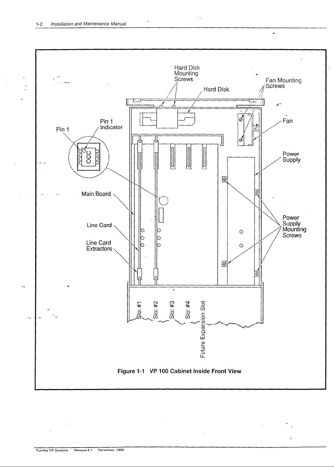
This section provides an overview of the VP.100 hardware. The VP 10 cabinet viewed irom the
front with- the plastic case removed and the metal enclosure opened is shown in Figure l-
n
VP 100 Cabinet
1.
The VP 100 is contained in a two-part enclosure:
Outer Enclosure
The outer enclosure is a plastic case. The case is intended as a
cosmetic enclosure. It hinges at the top and rotates down ok-er the
.metal enclosure. The plastic case locks at the bottom. On the inside
of the plastic case, a storage place is provided for a configuration
diskette and one spare fuse.
Each VP 100 cabinet is shipped fully assembled. The cabinet
specifications are as follows:
_ Height:
Width:
19.5 inches (49.5 cm.)
12.75 inches (32.5 cm.)
Depth: 5.75 inches (14.5 cm.)
Weight: 30-40 pounds (13-18 kg.)
.
. . _
Inner Structure
The inner structure is a metal enclosure. The function of the metal
enclosure is to provide good mechanical support for all the internal
subassemblies. This enclosure also provides an EM1 and E.SD shield.
Toshiba VP Systems
Release 6.1
~~sernbW. 1992
Page 11
installation and Maintenance Manual
1-2
_-
- Hard Disk
Mounting
.-
Pin 1
/Indicator 11
V
Sjcrews
, Hard Disk
14 /II II
I I,,,_/,
_
Fan Mounting
/
I
1 I /
I
I
II \\
1 Fan
Power
SUPPlY
Power
-.
. .
Toshiba VP Systems
Release 6.1
Figure l-l VP 100 Cabinet Inside Front View
December. 1992
Page 12
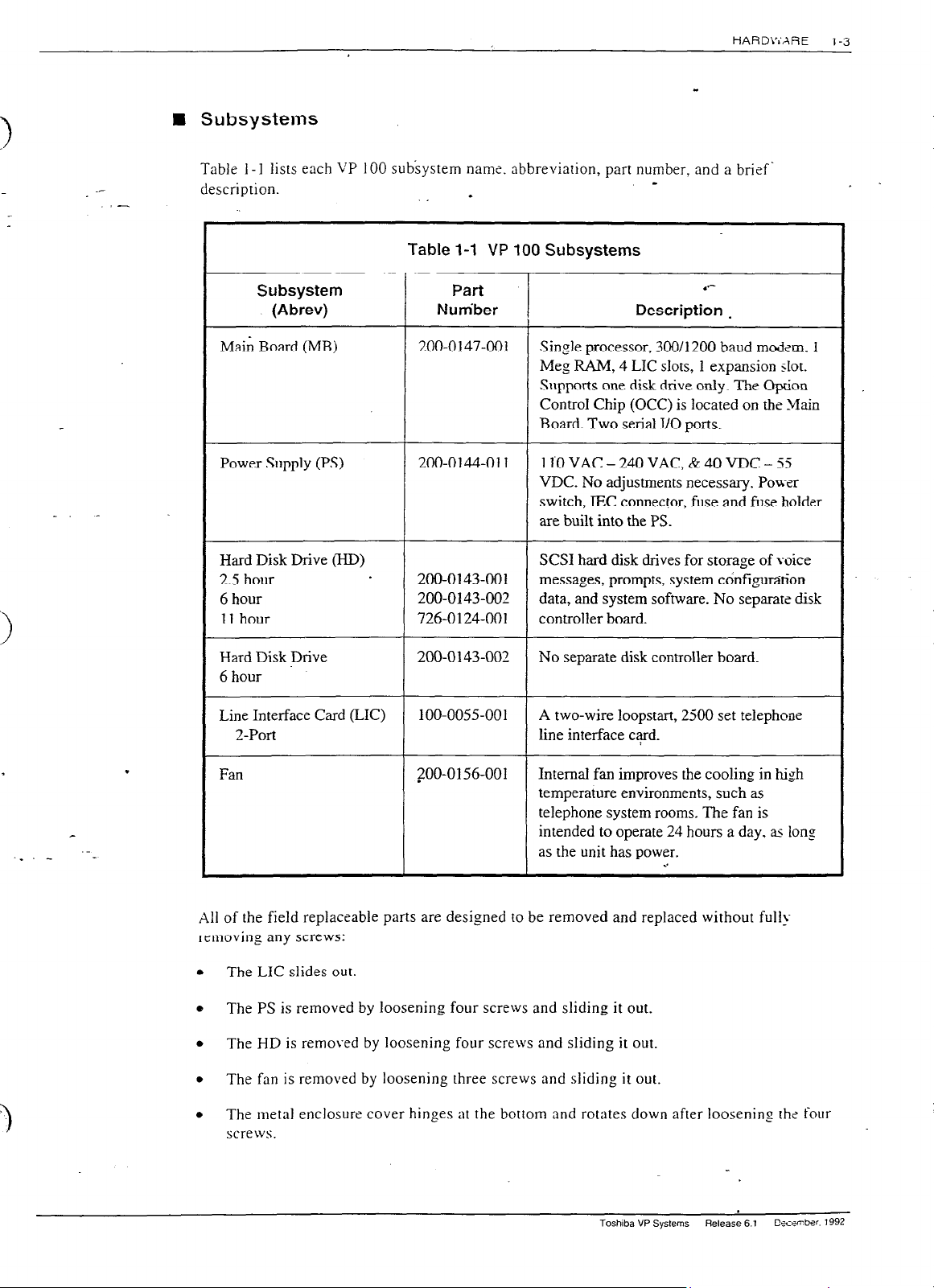
Subsystems
Table
1-l
lists each VP 100 subsystem nams. abbreviation, part number, and a brief‘
description.
I
Table l-1 VP 100 Subsystems
HARD\:‘XRE
l-3
. .
- _
Subsystem
(Abrev)
Main Board (MB)
Power Supply (PS)
Hard Disk Drive (I-ID)
2.5 hour
6 hour
11 hour
Hard Disk Drive
6 hour
Line Interface Card (LIC)
2-Port
Part
Nutiber
200-0147-001
Description
Single processor, 300/l 200 baud modem.
.*-
.
Meg RAM, 4 LIC slots, 1 expansion slot.
Supports one disk drive only. The oprion
ControI Chip (OCC) is located on the _&in
Board. Two serial I/O ports.
200-0144-011
110 VAC - 240 VAC, & 40 VDC - 55
VDC. No adjustments necessary. Power
switch, IEC connector, fuse and fuse holder
are built into the PS.
SCSI hard disk drives for storage of voice
200-0143-001
200-0143-002
726-0124-001
messages, prompts, system ctinfigutition
data, and system software. No separate disk
controller board.
200-0143-003 No separate disk controller board.
100-0055-001 A two-wire loopstart, 2500 set telephone
line interface card.
1
Fan
ZOO-01 56-001
Internal fan improves the cooling in high
temperature environments, such as
telephone system rooms. The fan is
intended to operate 24 hours a day, as long
as the unit has power.
. .
X11 of the field replaceable parts are designed to be removed and replaced without full!
removing any screws:
.
The LIC slides out.
.
The PS is removed by loosening four screws and sliding it out.
.
The HD is removed by loosening four screws and sliding it out.
.
The fan is removed by loosening three screws and sliding it out.
.
The metal enclosure cover hinges at the bottom and rotates down after loosenins the four
screws.
Toshiba VP Systems Release 6.1
C5.cwrb.x 1992
Page 13

Installation and Maintenance Manual
1-4
- _
_. -
Main Board
(MB)
The Main Board (MB) is the master control unit for the VP 100. The >lB contains a
microprocessor with ROM (Read Only M.emory) and 1 Megabyte R-Ah1 (Random
Accss
Memory), and two serial I/O ports..
The MB contains the system time-of-day clock which is backed-up by battery. The battery
maintains the correct time through power loss for up to 40 days.
.*-
The main features of the MB are:
.
Microprocessor.
.
1 Meg RAM.
.
4 line card slots.
.
1 expansion slot.
.
300/l 200 baud modem.
The VP 100 is provided with an internal 300/1200 baud modem, which is used for remote
testing and maintenance. You may communicate with the VP 100 through the internal
modem by using a 103A or 212A compatible modem-equipped terminal. The modem can
be accessed through any of the line ports on the VP 100.
Option Control Chip (OCC)
The Option Control Chip (OCC) is a non-volatile RAM component that stores optional
features. This component retains memory permanently, even in the case of power interruptions.
.
The OCC is programmed by Toshiba when the system is configured for shipment. All optional
features are added and removed Gmotely by Toshiba. The OCC is located on the Main Board.
The OCC must alwa?-s remain with the system it was purchased for. If the Main Board requires
replacement, the OCC must be transferred from the old Main Board to the replacement Main
Board. Refer to MAINTENANCE, Option Control Chip Replacemen‘i, in this manual.
Power Supply (PS)
B
The Power Supply (PS) provides all the DC voltage requirements for a maximum configured
system. The supply input voltage range is:
.
1OOVAC - 24OVAC.
.
48VDC.
Toshiba VP Systems
Release 6.1 December. 1992
Page 14

HARDW>:;IE
There are no straps or jumpers to be changed to select the different input ranges. The power
switch. IEC connector. and fuse are built into the power supply. The power supply ha- two
LEDs with the following functions:
.
Green
Red
If ON, power is on.
.
If OFF, there is no power.
.
ON during power up BOOT ROM diagnostic f&ting or u-hen
hardware errors have occurred.
.
Flashing slowly during auto-baud detect.
.
If the red LED is ON during normal operation, it indicates an
alarm condition.
.
OFF when system is functioning and no hardware errors have
been detected.
l-5
_. _
._ _
.
._
=
n
Hard Disk (HD)
The VP 100 uses a specially formatted 40,80 or 120 megabyte embedded SCSI- hard disk.
There is no separate disk controller board. The VP 100 supports one disk only.
Line Interface Card (LIC)
n
The Line Interface Card (LIC) provides a microprocessor-controlled interface to the PBX
extensions. Each LIC has two ports which connect to PBX extensions via line cords. The LIC
contains necessary circuitry for ring detection, dial tone detection, and signal power
measurement allowing up to 30dB of gain for recording messages. There is one DTMF
receiver for each port.
The LIC is a two-portstandard 2500 set interface with three LEDs on the card. The LED
functions are:
Red
.
.
.
. .
If ON, card is RESET or BAD.
If OFF, card is OK.
Yellow
.
There is one yellow LED for each channel.
.
The LED is ON kvhen the channel is in use.
.
The upper yellow LEDs are for the odd numbered ports:
and 7.
.
The lower yellow LEDs are for the even numbered ports: 1. -t. 6.
and 8.
Toshiba VP Sys!ems
Release 6.1
1.
3. 5.
DKw-ber 1992
Page 15

installation and Maintenance Manual
1-6
1.2
._
ADDITIONAL SUBSYSTEMS
,-
The follo\ving describes other hardware aspqcts of the VP 100. -
n
Terminal Ports
.*-
There are two terminal ports, TERM 1 abd TERM 2, which are used for terminal acceti and
RS-232C integration. respectively. The two interface cables Toshiba provides for connection
to these ports are the:
.
Laptop Interface cable
25
pin
.
Terminal Interface cable
25
pin
Both cables are forked; the single end connects to the laptop for the Laptop interface cable, or
to a terminal for the Terminal interface cable. The forked end connects to a VP 100.
n
TERM1
Terminal Port
1.
TERM 1, on the VP 100 can connect to a 103A/212A-compatible modem
or provide an RS-232C serial connection. It supports EIA standard RS-232C serial,
asynchronous (ASCII) data with 7 data bits, 1 stop bit, and even parity at the following
baud rates: 300. 6001 1200,2400,4800,9600, 19200, and 38400.
.
n
TERM2
Terminal Port 1 is used for special applications involving PBX integration. If a terminal is
attached to this port by mistake, the VP 100 responds with:
PLEASE USE COXNECT’OR FOR TERMINAL #I
Refer to INSTALLXTION, for RS232C pinouts and cables, and CONFIGURATIOl’
APPLICATIONS TERhIINAL, in this manual.
Auxiliary Connector (AUX)
Toshiba VP Systems
Release 6.1
The VP 100 uses an S-pin circular DIN-type connector for alarm relay connection and future
enhancements. The XUX connector allows additional signals to be transmitted to and from the
December. 1992
Page 16

HARDWME
VP 100. Currently. the only supported function is the alarm relay. Ths other pins on tis AUX
connector
are resen-sd for future applications.
l-7
._
-
.-
Relay Return
Relay d
Figure 1-2 AUX -Connector
B Alarm Reiay Operation
The following rable lists all possible states of the contacts on the alarm relay.
Table I-2 Alarm Relay Operation
State
Normal, Power ON
Power Failure
System Reser
Hardware Error Detected
Test Alarm (command)
n
Alarm Relay Electrical Requirements
The following are the alarm relay electrical requirements.
.
\Iaximum Voltage - 48 VDC or 50 VAC.
.
llaximum Current - 1 amp.
I Sxrw head nof to be more than .35”.
mmnt
the
VP 100 cabinet.
Action
Contacts open
Contacts closed
-
Contacts stay closed momentarily, rhen open
Contacts closed (contacts reopen when hardware error is
cleared)
. .
Contacts closed (contacts reopen when hardware error is
cleared)
Be
sure you have everything necessary if molly-bolts are
required
to
Page 17

2
- _
Section
2.1
_.
2.2
2.3
2.4
2.5
.-
.-
PREPARING THE PHONE SYSTEM
.
Chapter Contents
Description
How the VP 100 Works with the Phone System
Interfaced
Integrated
Answering Incoming Calls ..........................................................................................................
Acting as a Message Center ......................................................................................................
Determining Necessary Changes
Changes to Central Office
Additional Trunking
Splitting Trunk
Ordering CO
Changes to the Phone System
The VP 100
Called Extensions..
Trunks ........................................................................................................................................
Trunk Redirection..
Trunk Selection
Ordering Phone
Implementing the
Upgrade the PBX to a Feature Package Offering the DIL Feature
Use DID Numbers
Place the Console in Night Mode..
Arrange for Trunks to
Installations .............................................................................
Installations
Groups.. ..............................................................................................................
Trunking Changes..
Port Extensions
VP 100 on PBXs Without
...............................................................................................................
..............................................................................................
Trunking
.....................................................................................................................
.....................................................................................................................
...........................................................................
..........................................................................................................................
System Changes..
......................................................................................................................
Call Divert to
..................................................................................................
...............................................................................................
.........................................................................................................
......................................................................................................
............................................................................................
.............................................................................................
the VP 100 Ports..
...............................................................................
DIL Feature..
................................................................
.......................... .‘:.
_
~...................... ...........
. .........................................
............................................
.................................
I ......
,
Page
2-1
2-l
2-l
2-2
2-3
2-4
2-5
2-5
2-5
2-6
2-7
2-7
2-8
2-8
2-8
2-9
2-9
2-12
2-l 2
2-l 2
2-13
2-l 3
Figure
2-l
2-2
2-3
2-4
2-5
Figures
Description
VP 100 .....................................................................................
All Incoming Calls Answered
Incoming Calls
Sample Agency
Service Provider
Using Call Diverters to Direct Incoming Calls to the VP 100
Split Between Console
Letter for CO Changes..
Letter..
by the
and the VP 100..
..........................................................................................
....................................................................................................................
..................................................................
.............................................................
Toshiba VP Systems Release 6.1 Ce-rember. 1992
Page
2-2
2-3
2-6
2-10
2-13
Page 18

INTRODUCTION
The VP 100 works with PBXs, Centrex, most hybrids, and some key systems. For convenknce, this manual
usesThe terms “phone system” and “PBX” to refer to any telephone system that works with the VP 100. The
.-
terms
“extension” and “station” are used interchangeable.
This chapter discusses the VP 100’s connection to the phone system, the changes required. and how to order
them. It assumes familiarity with some PBX concepts.
Changes need to be made to the phone system for the VP 100. Some are changes to the PBX, others are
done in the Central Office (CO). This may require lead time. Work with the client to determine who will
make the changes and how long they will take. Prepare a schedule so everyone knows who is doing what
and the date each item is required.
l
*-
.
Page 19

PREPARING THE PHONE SYSTEM
i-l
HOW THE VP 100 WORKS WITH THE PHONE SYSTEM
I
.-
,-
Connections to the phone system vary depending on whether the installation is interfaced or
integrated.
n
The following. describes the.various options.
Interfaced Installations
Each VP 100 port is connected to a ZOO-type single-line, touchtone PBX extension. A
standard four-conductor modular line cord connects the RJI 1 jack on the VP 100 line card to
the PBX extension RJI 1 jack. A PBX extension connected to a VP 100 port is referred to as a
port extension.
In order for the VP 100 to extend calls correctly, each port extension must be configured in the
PBX to receive calls, place them on hold, initiate, transfer, and reconnect calls.
.A VP 100 port is in use during the entire time it takes to answer a call, dial the extension the
caller entered, and connect the caller to the requested extension. When the called party
answers, the VP 100 connects the caller to that extension and drops out of the connection. The
VP 100 port is then free to handle another call. When the called extension is busy or does not
answer, the VP 100 port remains occupied while calling another extension or taking a-message..
_A VP 100 port is in use when employees are listening to or sending messages.
Port extensions answering with the same company greeting and answering mode are placed iu a
hunting arrangement within the PBX. The hunt group may be circular or linear (terminal)
according to the requirements of each particular PBX. This assures that callers are answered by
the first available port.
.*-
.
.
._._ .-_
The mode (AX, CX, or MX) of the VP 100 port determines how calls are answered by the
VP 100. Refer to the
Integrated Installations
n
Different methods are used to integrate a telephone system with the VP 100. In some cases. a
combination of these methods may be used for full integration.
Integration is the ability of the telephone system, when the call is not answered by the VP 100.
to route or forward a call with information that identifies the extension number the call was
intended for, and in some cases, the extension number of the person initiating the call.
n
In-band Integration
In-band integration is the ability for a telephone system to send DTMF tones that identif>the extension number for a forlvarded call to the port extension answering the call. In-band
signalling may include the condition (busy, ring-no-answer, or direct) for the call. In
Configurafion
manual - PORTS.
Page 20
Installation at-d Maintenance Manual
2-2
certain installations, DTMF may be used to turn ON or OFF message waiting indicators
when messages are left or when the mailbox is entered.
n
RS-232C
Integrations
.
,
_
RS-232C integrations are similar to the Bell Operating Company’s (BOC) Simplified
LMessage Desk Interface (SMDI). The SMDI or RS-232C interface provides the directory
number, or PBX extension number of the called extension from which aKincomins call
was forwarded, to the message desk. If the call originated in the same CO or PBX. the
directory number or extension numb& is sent to the message desk.
.
The condition or reason the call was forwarded to the message desk, as well as the port or
member of the hunt group the call is being sent to, is included in the protocol. Message
waiting indication may be turned ON or OFF over RS-232C connections for most
installations.
n
Answering Incoming Calls
The VP 100 can answer all or a portion of a company’s incoming calls. Trunks can be directed
to the VP 100 hunt group instead of the operator through a PBX feature. This feature, often
called DIL (Direct In Lines), allows trunks to be directed to a specific extension or hunt group
instead of the console.
The PBX may be set up to direct al1 or only some incoming trunks to the VP 100.
For example,
the main company number may go to the attendant, while a second trunk group, with a different
listed directory number, can be directed to the VP 100. Ports answering incoming calls are
configured in AX mode.
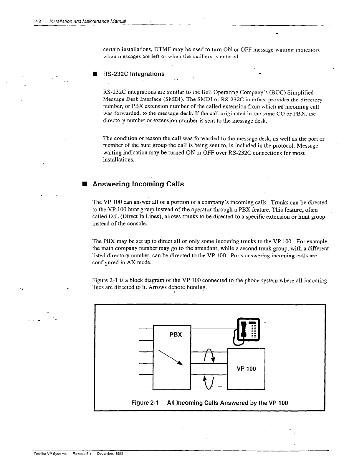
Figure 2-1 is a block diagram of the VP 100 connected to the phone system where all incoming
.
lines are directed to it. Arrows denote hunting.
.
Figure 2-1 All Incoming Calls Answered by the VP 100
Toshiba VP Sysems Ran 6.1
December. 1992
Page 21

PREPARING THE PHONE SYSXM
Figure 2-2 is a block diagram,of the VP 100 connected to a phone system that has in<c7ming
lines split between the console and the VP 100.
Arrows denote hunting.
.‘-
2-3
_. -
‘I
._ _ .-=
I
Figure 2-2
-a Acting as a Message Center
The VP 100 can also be set up to answer forwarded calls and act as a message center. For
example, a company with’centrex service already has a means of getting calls dire&\- to a
station. When the station is busy or does not answer, the station can be forwarded to I, VP 100
hunt group to take a message. Ports receiving forwarded calls are configured in CX mode. The
VP 100 does not attempt to call the extension number entered by the caller but imme&tely
goes to that extension’s mailbox and offers to take a message.
The attendant may also extend callers to a VP 100 port to allow them to leave a voice message.
This port is configured as MX mode. As with CX mode, it does not call the extension number
entered but goes to that extension’s mailbox and offers to take a message.
.
Incoming Calls Split Between Console and VP 700
I
Toshiba VP Systems
Release 6.1
:e.:-;mwr 1992
Page 22
2-4 installation and Maintenance Manual
2.2
- _
DETERMINING NECESSARY CHANGES
.-
A survey of the existing phone system. is done durin,
process. From the descriptions of the application(s), decisions are made about how_the VP
should be used. Refer to the
Product Description
questions to ask during the survey.
Use the results of the survey and the type of application to determine the necessary changti.
Schedule and track these changes using the checklist found in the INSTALLATION chapter.
Testing the Installation and Telephone Changes.
For convenience, we separated CO trunk changes from PBX changes. The following sections
discuss changes that may be required and guidelines for ordering the changes for both CO uunking
and the PBX.
0 the initial phase of the implementation
100
manual - IMPLEMENTATION for a list of
.
Toshiba VP Systems Retease 6.1
.
December, 1992
Page 23
PREPARING THE PHONE SYSTEM
2-5
2.3
- _
_. _
CHANGES TO CENTRAL OFFICE TRUNKiNG
Central Office (CO) changes may be needed t-o:
Add trunking capability.
Change the order of trunk hunting.
.*-
Create new trunk hunting groups.
Add, change, or delete InWXTS (l-800) services.
Add, change, or delete DID or Centrex services.
Split the hunt group (directory listed number), allowing some trunks to be directed to the
console and some to the VP 100.
i
Additional Trunking
The specific number of PBX lines and trunks depends upon the number of VP 100 porrj and the.
desired tnmking arrangement.
Although the VP 100 port drops off after it transfers a call, the CO trunk is still occupied
during the entire call. When you decide how many trunks to direct to the VP 100, remember
each trunk is occupied,from the time the call is placed until the caller hangs up_ As a result.
the VP 100 can answer incoming calls from more trunks than it has ports.
Determine how many trunks to direct to the VP 100 by using PBX traffic data and the traffic
.
engineering tables. The tables are designed to help decide how to use the VP 100 most
effectively for a given situation. ‘After collecting the traffic data, it may be necessary to order
changes from the telephone company to add or alter the number of trunks.
Splitting Trunk Groups
c
If one two-way trunk group will be separated into two or more groups, the rotary hunting of the
trunks must be changed.
The VP 100 only handles incoming calls. If the trunks the VP 100 answers are two-way trunks.
(also used for outgoing calls) make sure that sufficient trunks are available for both incoming
and outgoing calls. Additional trunks or changes to the type of trunks may be advisable.
Toshiba VP Systems
Release 6.1
Csrrmber. 1992
Page 24
lnstalla:~in and Maintenance Manual
2-6
n
‘,
Ordering CO Trunking Changes
__
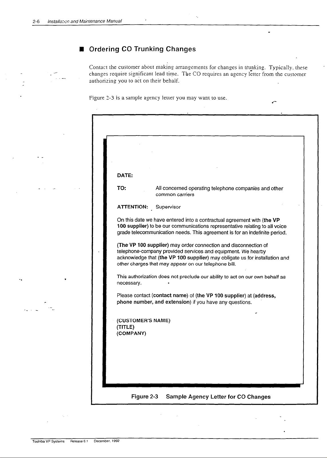
Contact the customer about making arrangements for changes in ti-unking Typically. these
.-
changes require significant lead tive. The CO requires an agency letter from the customer
authorizing you to act on their behalf.
Figure 3-3 is a sample agency letter you may want to use.
DATE:
TO:
ATTENTION: Supervisor
On this date we have entered into a contractual agreement with (the VP
100 supplier) to be our communications representative relating to all voice
grade telecommunication needs. This agreement is for an indefinite period.
All concerned operating telephone companies and other
common carriers
.*-
(The VP 100 supplier)
may order connection and disconnection of
telephone-company provided services and equipment We hearby
acknowledge that (the VP
100 supplier)
may obligate us for installation and
other charges that may appear on our telephone bill.
.
This authorization does not preclude our ability to act on our own behalf as
necessary.
Please contact
phone number, and extension)
.
(contact name) of (the VP 100 supplier) at (address,
if you have any questions.
. .
(CUSTOMER’S NAME)
(TITLE)
(COMPANY)
Figure 2-3 Sample
Agency Letter for CO Changes
Toshiba VP Systems
Release 5 7
December. 1992
Page 25

PREPARING THE PHONE Sh’S-EM
2-7
2.4
- _
CHANGES TO THE P.HONE SYSTEM
.-
Changes may be requirsj to the following:
.
The VP 100 port extensions.
.
Called extensions.
.
Trunks.
- Redirection.
- Selection.
Additional equipment ma)’ be required before these changes can be made. Most changes ane to the
PBX database.
n
The VP 100 Port Extensions
Connect and configure the port extensions using the following steps:
.
.--
!
1. Designate one 2500-type, single-line, touchtone extension for each VP 100 port. _%ldirional
PBX line circuits may be required.
2. Terminate each of these extensions on an RI1 1 or equivalent jack. Clearly mark exh jack
with the extension number.
3. Assign a PBX class of service to these extensions permitting them to:
.
.
Initiate calls.
.
Receive (incoming) calls.
.
Place calls on hold.
.
Transfer calls.
.
Forward calls.
.
4. Remove any type of call waiting features from the VP 100 port extensions.
t@ If configuring ports for outcalling to network locations for off-site message
notification or for off-site alarm calls, make sure the port extensions are not
restricted from making calls to these locations (e.g., toll restriction).
5. Set up a hunt group for each group of port extensions configured to answer in the -Jrne
way (company greeting, intercept position, mode). Where possible. make these cir<:ular
hunt groups.
Toshiba VP Systems
Release 6.1
:~_r:;rnbe, 1992
Page 26

lnstal~ation and Maintenance Manual
2-8
._
.-
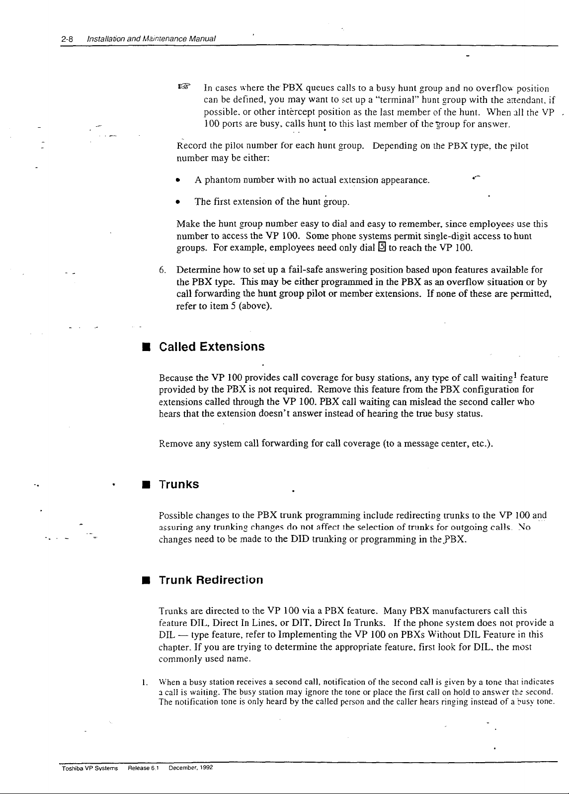
t@? In cases Lvhere thePBX queues calls to a busy hunt group and no overflow position
can be defined, you may want to set up a “terminal” hunr group with the arrendsnt. if
possible. or other intercept position as the last member of the hunt. When all the
100
ports are busy, calls hunt to this last member of the 2roup for answer.
.
Record the pilot number for each hunt group. Depending on the PBX type_ the pilot
number may be either:
VP _
- _
_. _
.
A phantom number with no actual extension appearance.
0
The first extension of the hunt group.
.‘--
Make the hunt group number easy to dial and easy to remember, since employees use this
number to access the VP 100. Some phone systems permit single-digit access to hunt
groups. For example, employees need only dial g to reach the VP 100.
6. Determine how to set up a fail-safe answering position based upon features available for
the PBX type. This may be either programmed in the PBX as an overflow situation or by
call forwarding the hunt group pilot or member txtensions. If none of these are permitted,
refer to item 5 (above).
n
Called Extensions
Because the VP 100 provides call coverage for busy stations, any type of call waiting] feature
provided by the PBX is not required. Remove this feature from the PBX configuration for
extensions called through the VP 100. PBX call waiting can mislead the second caller who
hears that the extension doesn’t answer instead of hearing the true busy status.
Remove any system call forwarding for call coverage (to a message center, etc.).
._ -
Toshiba VP Systems
._
.
n
1.
Release 6 t
Trunks
.
Possible changes to the PBX trunk programming include redirecting trunks to the VP 100 and
assuring any trunking changes do not affect the selection of trunks for outgoing calls. 90
changes need to be made to the DID trunking or programming in the.PBX.
Trunk Redirection
Trunks are directed to the VP 100 via a PBX feature. Many PBX manufacturers call this
feature DIL, Direct In Lines, or DIT, Direct In Trunks. If the phone system does not provide a
DIL - type feature, refer to Implementing the VP 100 on PBXs Without DIL Feature in this
chapter. If you are trying to determine the appropriate feature, first look for DIL, the most
commonly used name.
When a busy station receives a second call, notification of the second call is given by a tone tha1 indicates
a call is waiting. The busy station may ignore the tone or place the first call on hold to ans\ver ths second.
The notification tone is only heard by the called person and the caller hears ringing instead of a busy tone.
December. 1992
Page 27

PREPARING THE PHONE SY_=-Zkl
2-7
2.4
- _
_-
CHANGES TO THE PHONE SYSTEM
.-
Changes may be require; to the following:
.
The VP 100 port exr?nsions.
.
Called extensions.
.
Trunks.
- Redirection.
- Selection.
Additional equipment ma_v be required before these changes can be made. Most changes are to the
PBX database_
IU The VP 100 Port Extensions
Connect and configure the port extensions using the following steps:
.
._ -
._
1. Designate one YKLtype, single-line, touchtone extension for each VP 100 port_ _Uditional
PBX line circuits may be required.
2. Terminate each of these extensions on an
RJl 1 or equivalent jack. Clearly mark esh jack
with the extension number.
3. Assign a PBX class of service to these extensions permitting them to:
.
Initiate calls.
0
Receive (incoming) calls.
0
Place calls on hold.
0
Transfer calls.
.
Forward calls.
.
4. Remove any type of call waiting features from the VP 100 port extensions.
6~ If configuring ports for outcalling to network locations for off-site message
notification or for off-site alarm calls, make sure the port extensions are not
restricted from making calls to these locations (e.g., toll restriction).
5. Set up a hunt group for each group of port extensions configured to answer in the c-tme
way (company greeting, intercept position, mode). Where possible. make these circular
hunt groups.
Toshiba VP Systems
Release 6.1
:+::tmcr ,992
Page 28
/nsta//ab;on and Akmienance Manual
2-8
t@
In cases
where the PBX queues calls to a busy hunt group and no overflou position
can be defined, you may want to set up a “terminal” hunt group with the ansndanr. if
possible. or other intercept position as the Iast member of the hunt. When 211 the VP . .
100 ports are busy. calls hunt to this last member of the 3oup for answer.
.
Record the pilot number for each hunt group. Depending on the PBX type! the pilot
number may be either:
_. _
.
A
phantom number with no actual extension appearance.
.
The first extension of the hunt group.
.*-
Make the hunt group number easy to dial and easy to remember, since employees use this
number to access the VP 100. Some phone systems permit single-digit access to hunt
groups. For example, employees need only dial
q
to reach the VP 100.
6. Determine how to set up a fail-safe answering position based upon features available for
the PBX type. This may be either programmed in the PBX as an overflow situation or by
call forwarding the bunt group pilot or member extensions. If none of these are permitted,
refer to item 5 (above).
Called Extensions
n
Because the VP 100 provides call coverage for busy stations, any tvp of call waiting’ feature
provided by the PBX is not required. Remove this feature from the PBX configuration for
extensions called through the VP 100. PBX call waiting can mislead the second caller who
hears that the extension doesn’t answer instead of hearing the true busy status.
Remove any system call forwarding for call coverage (to a message center, etc.).
-.
Toshiba VP Systems
.
n
1.
Release 6 1
Trunks
.
Possible changes to the PBX trunk programming include redirecting trunks to the VP 100 and
assuring any trunkinp changes do not affect the selection of trunks for outgoing calls. 90
changes need to be made to the DID trunking or programming in the.PBX.
Trunk Redirection
Trunks are directed to the VP 100 via a PBX feature. Many PBX manufacturers call this
feature DIL, Direct In Lines, or DIT, Direct In Trunks. If the phone system does not provide a
DIL - type feature, refer to Implementing the VP 100 on PBXs Without DIL Feature in this
chapter. If you are trying to determine the appropriate feature, first look for DIL, the most
commonly used name.
When a busy station
a call is waiting. The busy station may ignore the tone or place the first call on hold to ans\ver rhz second.
The notification tone is only heard by the called person and the caller hears ringing instead of a Busy tone.
December, 1992
receives a second call, notification
of the second call is given by a tone that indicates
Page 29
- _
_. _
PREPARING THE PHONE SYSTEM
If you
can talk with someone.familiar with the phone system. describe the feature (i.e.. “ability
to direct a trunk or
goup
of trunks
to
a spscit>c estension or hunt group rather than being
directed fo an attendant console-for ans~v&‘*). They should be able to supply the name of the
feature for that phone system.
.
Trunk Selection
With some phone systems, incoming cal.ls hunt from the beginning of a td;k group (trunk 1,
trunk 2,...) for an available trunk, while out,going calls hunt in reverse order (trunk IO. trunk 9,
. __).
Others specif>- the first and second preference trunk groups for both incoming and
outgoing calls. If a large two way trunk group is to be split, re-examine the PBX programming
for outgoing trunk selection and determine thz trunk group to use for outgoing calls.
Ordering Phone System Changes
n
If your company is not the PBX provider, order changes from the PBX vendor on behalf of the
customer. Provide a Service Provider Letter (Figure 3-4) to the PBX-vendor indicating the
changes needed to the PBX for the VP 100, and schedule the changes. If possible, try to use
that PBX’s terminology when requesting these changes. You may also want to provide them
with information from this chapter. Review the previous sections of this chapter for iuformation
to fill in the blanks. Read over the letter and in particular, the footnotes. Depending upon the
application, portions of the letter may need to be expanded upon or deleted.
2-9
.
>
..I
.
Toshiba VP Sysiems
Release 6.1
&,:amber 19%
Page 30
2-10
lnstaJ &on and hlaintenance Manual
,
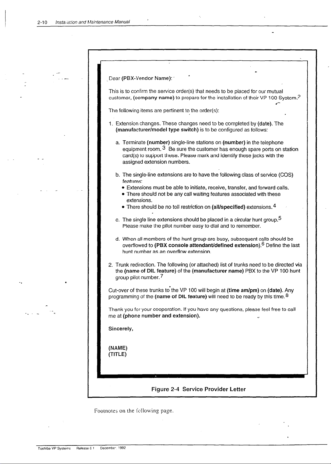
Dear (PBX-Vendor Name):.
*
This is to confirm the service order(s) that needs to be placed for our mutual
customer, (company name) to prepare for the installation of their VP 100 System?
.‘--
The following items are pertinent to the order(s):
I. Extension changes. These changes need to be completed by (date). The
(manufacturer/model type switch) is to be configured as follows:
a. Terminate (number) single-line stations on (number) in the telephone
equipment room. 3 Be sure the customer has enough spare ports on station
card(s) to support these. Please mark and identify these jacks with the
assign& extension numbers.
b. The single-line extensions are to have the following class of service (COS)
features:
l
Extensions must be able to initiate, receive, transfer, and forward calls.
l
There should not be any call waiting features associated with these
extensions.
l
There should be no toll restriction on (alvspecified) extensions.4
c. The single line extensions should be placed in a circular hunt group.5
Please make the pilot number easy to dial and to remember.
d. When all members of the hunt group are busy, subsequent calls should be
overflowed to (PBX console attendant/defined extension).6 Define the last
hunt number as an overflow extension.
2. Trunk redirection. The following (or attached) list of trunks need to be directed via
the (name of DIL feature) of the (manufacturer name) PBX to the VP 100 hunt
.
group pilot number.7
Cut-over of these trunks tdthe VP 100 will begin at (time am/pm) on (date). Any
programming of the (name of DIL feature) will need to be ready by this time.8
Thank you
me at (phone number and extension).
for
your cooperation. If you have any questions, please feel free to call
. .
Sincerely,
(NAME)
(TITLE)
Figure 2-4
Service Provider Letter
Footnotrs on the following page.
Toshiba VP Systems
Release 5
Decembe- 1992
1
.
Page 31

PREPARING THE PHONE SYSTEM
2-11
.-
-
c
._ _
The vendor, especially for CO Centrex, may ask for the VP 100’s registration:
1.
FCC Registration
Ringer Equivalence
PBX Interface
Line card
The VP 100 unit
UL Registration
e
Or other location where the VP 100 unit will be placed. Refer to the environmental requirements in
3.
EQ99TB-60697-VM-T
0.3A
RJllCorRJllW
meets FCC Part 68
meets FCC Part 15, Class A
ES2470(S)
INSTALLATION, Installation Requi;ements, in this manual.
For ports that are used for networking, off-site message notification or off-site alarm call.
1.
._
If more than one hunt group is required, specify the number of extensions for each hunt group.
5.
For example:
hunt group #I 6 extensions
hunt group #2 2 extensions
May not be available for all PBXs. If possible and desired, include this item.
6.
If there is more than one group of trunks, specify the trunks for each hunt group:
7.
Hunt group # 1
Trunks: Hunt group #2 1-800-337-I 100
555-3700 1-800-337-l 101
555-3701
555-3702
555-3703
Tailor this section to the customer’s needs. If trunk cut-over is staggered, include schedule in this Ietrer. If
S.
a PBX representative needs to be on-site for this cut-over, arrange a mutually convenient time wirh rhe
PBX vendor.
Toshiba VP Svstems Release 6.1
kmber. 1992
Page 32

lnstallario- znd Maintenanc? Manual
2-12
IMPLEMENTING THE VP 100 ON PBXS WITHOUT DIL
FEATURE
- _
-. _
.-
You may encounter a PBX with an older feature package that does not provide the-DIL fertture.
The PBXs most frequently encountered without DIL are AT&T Dimension PBXs with Feature
Packages (FP) 2, 3,-t. 5, and 7.
s This feature on the Dimension is called DDC for Direct Department Calling. It is only
available on feature packages (FP) 8, 10, 12, and 15.
If the customer’s Dimension does not have FP8 or later or it is a phone system that does not have a
DIL feature. there are several alternatives for getting trunks to the VP 100 ports for answer.
.
Upgrade the PBX to a feature package offering the DIL feature.
.
Use DID numbers.
.
Place the console in night mode.
.
Use call diverters to switch calls to the VP 100 ports.
Not all these alternatives may be feasible for a given situation. The following discusses each in
detail.
.
.*-
._ _
._
n
Upgrade the PBX to a Feature Package Offering the DIL Feature
Depending upon the customer’s current version, this may not be economically feasible. This is
the most straightforward solution, but possibly not the most practical.
.
n
Use DID Numbers
Some customers may already have a block of DID numbers but do n9t wish to pay for DID
numbers and trunks for all employees. Callers may be given a number that is a DID extension
answered by the VP 100. This is especially suitable where a second number (not the main
company number) is to be established for company employees, friends, family and frequent
callers to call to reach extensions or receive information.
Again, in this way the VP 100 can answer a DID number. However, InWATS or main
company numbers cannot be answered this way. Due to the cost of instalhng DID, this may
only be attractive to companies that already have DID. DID is used only to get calls to the VP
100 extensions.
Toshiba VP Systems
Fl?w_EE 6.1 December. I!392
Page 33

n
Place the Console in Night Mode
PREPARING THE PHONE SYSTEM
2-13
__
Even if the PBX does not have ihe DIL feature, placin
.-
be used to direct all incoming trunks to_a certain extension (such a< the VP 100 hunt group).
However, once the console has been placed in night mode, it may not be used. Direct callers
g the console in night mode us’ually may
.
requiring assistance (through the VP 100) to a multi-button key set for answe@ng. This
solution therefore, is most practical for:
.
Smaller companies having a single console and willing to direct all trut$s to the VP 100.
.
Companies using the VP 100 only to answer after hours and on weekends..
Since the console cannot be used, callers who are toll restricted cannot get an outside line from
the operator.
n
Arrange for Trunks to Call Divert to the VP 100 Ports
When only some trunks are to be answered by the VP 100 (ruling out Console Night Xlode),
these trunks can be removed from the PBX and terminated on call diverters that are connected
to PBX extensions. See Figure 2-5. These call diverters are programmed to call the VP 100
hunt group. The call diverter answers the trunk and calls (through the PBX) the VP 100 hunt
group number. The appropriate number of VP 100 ports, as well as one additional extension
per trunk to be diverted to the VP 100, are required.
VP 100
.
For each incoming
trunk to be answered
PBX
*
by VP 100
VP 100
. .
Figure 2-5 Using Call Diverters to Direct Incoming Calls to the VP 100
The call diverter that operates satisfactorily in this situation is the BUSCOM 200%RD
manufactured by MetroTel. Because this diverter ordinarily allows remote turn-off by pressing
a fl key, it requires a modification.
When ordering from MetroTel, (408/988-5200) specify the
“OPCOM/Toshiba VP inhibit remote turn-off modification.”
Toshiba VP Systems Release 6.1
?XFT.bW. 1992
Page 34

.-
.-
CONFIGURATION APPLICATIONS
TERMINAL
Chapter Contents
. . _
Section
3.1
_. _
3.2
3.3
3.4
Appendix A
Figure
3.1
Description
VP CAT @erview
DOS Information
VP CAT Program Description
VP 100 Software Package Description..
PC Hardware Requirements
Terminal Conventions
laptop PC Description and Setup
Initial Setup
DOS Setup
VP 100 Software Package installation
Install VP CAT Software
VP 100 System Software Installation
VP 100 System Prompts Installation
Reboot the PC
Floppy Diskette Write Protection
Communication with the VP 100 .......................................................................................................
Connecting to the VP 100..
Port Connection
.
Estabiishing Communication (Autobaud
Changing the Baud Rate.
DOS Commands
............................................................................................................................
........................................................................................................................
....................................................................................................
.................................................................................... 3-2
.................................................................. T ...................................
................................................................................................................
....................................................................................................
................................................................................................................................
.
...................
...........................................................................................................................
........................................................................................
..............................................................................................
............................................................................................................
.........................................................................................
.........................................................................................
_..____.___Le
...............................................................................................
........................................................................................................
.........................................................................................................................
Detect)
...........................................................................................................
..............................................................................................................................
_
.
..........................
.
............................................
Page
.......
’
3-l
3-1
3-1
3-4
3-5
3-7
3-7
3-7
3-8
3-8
3-9
3-l 0
3-10
3-l 1
3-t 2
3-12
3-13
3-13
3-14
3A-1
<.
Description
Back
View of a Floppy Diskette Write Protect _...._._............................................................. _____ _..__... 3-l 1
Page
Toshiba VP Systems
l+de’ase 6.1
~xc?mber. 1992
Page 35

INTRODUCTION
- _
_-
_
This chapter explains how to set up a PC for use as CL- VP Configumtion Application Terminal (C;\T).
Setup and basic operation of the CAT are explained 1 this chapter. For information about DOS and DOS
commands, refer to the manuals that were provided G:-h your PC. or contact your PC vendor.
The CAT is used to initiate the procedures described 3 this chapter. The CAT is an IF&i compatible PC
with a floppy drive and an internal hard disk drive.
l
The CAT floppy drive is used to transfer program and files to and from the CAT hard disk drive.
0
The CAT hard disk drive is used to store the C.%T program, VP 100 system software, prompts. and
backed up system configurations. It is also used :-hen transferring proLgrams and files to and from the
VP 100.
Most standard ASCII data terminals that meet EIA RS-332C specifications can be used to communicate
with the VI’ 100. These ASCII terminals can be used :o access all configuration, reporting, and diagnostic
proLgrams on the VP 100.
The CAT is used with multiple VP products. If the C-IT hard disk drive contains information for more
than one product type, the following screen appears Gen the CAT is first turned ON. It does not appear if
only one product type is installed. This screen allow- :;ou to select the VP product being used.
Use * and W to move selector and ENTER to make selection
Select Product Type
_
_
.
wvfxwol-ks
ma
.
VMX CAT version XXX
(c) 1989,199O by VMX, Inc.
Toshiba VP Systems
Release 6.1
C!.xsmber. 1992
Page 36

__
. . _
CONVENTIONS:
To indicate the difference between the text in this chapter. the following conventions are follou-&.
Text
This is normal text in this chapter.
VP 100
and DOS
system prompts
VP 100
screen
sample
User entries within
VP 100
screens
The VP 100 system prompts and DOS prompts are re@esented in this
type:
C:\VMXCAT>
‘j%e VP 100 system commands and DOS commands that you typ.k are
represented in this type:
.M USER
.MUSER
1 Enter
current
MAILBOX &I&H.
:50@
Enter each user’s MAILBOX and COSJZnter as:
Mailbox,COS (Mailbox=l-8 digits, COS=O-127)
User’s EXTENSION will be set to match MAILBOX.
MOD500,O
.___
Toshiba VP Systems
‘-_
CAT Menus
The names of CAT Menus are represented in &is type:
Terminal Menu
t@ The various screens described in this chapter appear ONLY when using the CAT.
Release 6.1
December, 1992
Page 37

Quick Reference Guide
.-
.
.-
Configuration
Applications Terminal
Tips and Notes
Sta_rting the CAT
The CAT pro_gram starts automatically each time the PC’s power is turned ON.
Restarting the PC
Iffor
any reason the CAT program becomes inoperative, the CAT can be reset by holding down the following keys
simuhaneously. This reset is similar to turning the PC’s power OFF then ON.
Starting the VMX CAT Program from DOS
-
Move into the VP CAT Directory.
Type:
From the C:L
CD\ -1
CD VMXCAT -1
prompt, type:
.
The C:\VMXCAT> prompt is displayed.
.
From the
C:\VMXCAT>
*-
prompt; type:
Starting with
log file closed
Clearing the
Screen
CAT [options] -1
.
where [options] can be
/T1600
(Toshiba), /Z286 (Zenith), or /COM2 (mod$m).
r@ The VP CAT starts with the Select System screen displayed.
To start the CAT program with the
log
file closed, use the CAT/LOGOFF command line
To clear the CAT screen without affecting the VP 100:
1. Enter the Terminal
2. Select
Clear Screen
Menu
( m
T).
from the menu choices.
3. Press [Enter].
Toshiba VP Systems
Release 6.1
option.
C+xeer. 1992
Page 38

- Quick
Commonly Used DOS Prompts
I%%
provides a prompt to indicate when it is ready to receive and process commands. The following are
prompt information:
Reference Guide
..-
.
Configuration Application& Terminal
Tips and Notes
examples
of DOS
Prompt
c:>
C:b
C:\VMXCAI,
Moving from the “Select System” screen to the CAT menus
.
Press
the
JEscapel
-.
.
Hold do&r the a key and press the H key. The CAT menu appears with the Help option selected.
.
Use the left and right arrow keys to select the desired menu option.
‘.
Moving from
Hold down the a key and press the first letter of the VP CAT menu item you wish to select. The menu bar appears at the
top of the screen with that menu item highlighted:
the
Description
DOS prompt, not indicating what directory is selected. Most likely, the VP CAT software has not been
installed or the PC was not rebooted after VP CAT software was installed.
DOS prompt with the mot directory selected.
DOS prompt with the VP CAT directory selected.
key.
. .
VP 100 screen to the VP CAT menus
aH
(Alrl
E or m X Exit the CAT program and return to the DOS prompt.
FIT
aB
l=JR
iAltlU
Toshiba VP Systems
Help.
Terminal (VP CAT activities).
Backup information from the VP 100.
Restore information to the VP 100.
Update the VP 100 system software.
Release 6.1 December. 1992
Page 39

VP CAT OVERVIEW
., CONFIGURATION APPLICATIONS TERM ?IAL
3-l
- _
_. _
__
.-
The Configuration Applications Terminal (referred to as CAT) is a computer that combines Toshiba
approved IBM PC compatible hardware and Toshiba supplied CAT softvvare.
b WARNING 4
The hardware component of the CAT should be dedicated exclusively to
installing and maintaining Toshiba products. Any application so’fiware.
programs, or files present on the PC hard disk drive or in RAM (memory) are
not recommended by Toshiba and they may interfere with VP 100 operation
and CAT software. Do not modify any programs or files supplied by Toshiba
as this will result in unpredictable operation of the CAT and/or the VP 100.
B DOS Information
To operate correctly, the CAT program requires DOS version 3.3 or later to be installed on the
PC hard disk drive in a subdirectory named “DOS.”
configuration, and prior to installing CAT or VP 100 system software.
Complete step-by-step procedures for all CAT operations that use DOS are provided in this
chapter. However, efficient use of the CAT requires a working knowledge of DOS commands.
DOS knowledge is necessary to be able to manage log files (captured during a communication
session with a VP loo), and to archive, recover, or delete VP 100 system configurations from
the PC hard disk drive. The DOS manual supplied with your PC is an excellent source of
information. as well as various PC books written for new users. Specifically, you should have a
working knowledge in the following areas:
This must be done during the PC setup and
0
PC root directory and subdirectories.
l
Xioving between directories_on the hard disk.
l
Operation of files with extensions .EXE, .COM, and .BAT.
0
DOS conventions for command options.
0
Purpose and use of AUTOEXEC.BAT and CONFIG.SYS files.
0
PC ke!-board and keystroke entry.
n
VP CAT Program Description
The C.-IT has two major functions:
l
Perform terminal emulation for communication with the VP 100.
.
Provide a method to perform the following operations:
Backup and Restore VP 100 System Configuration.
-
Page 40

3-2
installation
arc
Maintenance Manual
_
- Backup and Restore VP 100 Greetings, Names, Script, and Sequential Messages.
- Archive and Recover VP 100 System from floppy diskette.
_
-
Update VP 100 System Software.
- Beginning with Rel. 6.1, add a prompt set in a second language to the VP 100.
CAT Terminal
Emulation
Terminal emulation allows the CAT to communi&e with rhe VP 100
directly through a cabled connection or remotely thropgh a modem.
Characters typed on the CAT keyboard are sent to the VP 100, and
information from the VP 100 is displayed on the CAT monitor. The
only time the CAT is not performing terminal emulation is when
menus are displayed. At this time, communication with the VP 100 is
temporarily suspended because the menus control the terminal.
Data Transfer
Operations
The-CAT uses a proprietary packet-based, error-correcting data
transfer protocol at speeds‘up to 38400 baud, to pass information
between the VP 100 and the CAT. Data transfer is initiated by a menu
selection of the Backup, Restore, or Updatl: programs_ The Backup
options transfer data from the VP 100 to the CAT hard disk drive.
The Restore and Update options transfer data from the CAT hard disk
drive to the VP 100.
Program Utilities and
Other Features
The CAT program includes utilities to manage individual XI’ 100
systems. Systems can be added, deleted, and modified. Backed up
system configurations can be archived to and recovered from a floppy
diskette.
_
._
The CAT program also includes utilities to manage log files. which
capture communication sessions from the VP 100. Multiple log files
can be stored, displayed, printed, and deleted for each VP 100 defined
within-the CAT program.
n
._
_
VP 100 Software Package Description
The VP 100 PC software package consists of:
l
CAT software, terminal emulation, data transfer program, and program utilities
(1 diskette).
0
VP 100 System Software
l
VP 100 System Prompts (multiple diskettes).
(1
diskette).
The following diagram illustrates the directory structure of the PC hard disk after the VP 100
Software Package has been installed. A file is indicated by
<file name>
and a directory is followed
ivith a \ (backslash).
Toshiba VP Systems
Relee= 6 1
December. 1992
Page 41

., CONFIGURATION APPLICATIONS TERM ‘I.~L
r
3-3
. . -
- _
._
files
I
The following describes the VP 100 Software Package programs, directories, and files. and
explains how they are organized on the PC hard disk.
VMXCAn
CAT-EXE
.
RLxxyyzz.1 oo\
files
I
Directory used to store the executable CAT program and all C.\T
program utilities. Various subdirectories within VMXCAlI m used
to store VP 100 system software, VP 100 system prompts. individual
system configuration, and log file (session) information.
The
executable CAT software program file.
For each release of VP 100 software installed on the PC hard disk
drive, there is a subdirectory below VMXCAn named RLsxb-l;zz. 100
(for Release A.xx.yy.zz.) For example, Release A.06.01.02 hs a
subdirectory RL060102.100.
I
I
GNSSM\
Greetings,
Names, et&
<lOO.G>
<I OO.N>
PRMxxxxx.1 OO\
SNxxxxxx.1
OO\
For each version of VP 100 prompts installed on the PC hard disk
drive, there is a subdirectory below VMXCAA named
PRMxxxyz.100 (xxx = language, y = system release level. z = prompr
revision level.). For example, English Prompts 6K are stored in
subdirectory PRMENG6K. 100.
For each system that has been added, a subdirectory is autom:ticslly
created below VMXCAT\, and is named SNxxxxxx. 100, where
xxxxxx is the serial number of the system. For example, a syricm
with the Serial Number 000246 would have a subdirectory
S~OOO246.100. This subdirectory is used to store configurati*>n
backup files and the CAT.LOG file(s) for the specified sysrer?.
Toshiba VP Svsrems
Release 6.1
&:*mkr. 1992
Page 42

3-4 lnstallanm and Maintenance Manual
_
- _
GNSSM\
There is one subdirectory below every SNxxxxxx. 100 nam,it
GNSSXI. This subdirectory is used to backup Greetings. Tames.
Scripted. and Sequential Messages.
-
CAT.tOG
File used to store a communication session with a selected L-P
.
100
on
the CAT hard disk drive. This text file can be saved, deleted_ vie\ved
and printed. The file is automatically created and/or updateif
(appended) before each communication session w&h a selected VP
100 system. Logging to this file can be turned ON and OFF as
required. Refer to PROCEDURES, Session Review Arid File
Maintenance, in this manual for complete details.
Unauthorized changes to data in any file stored in the VMXCATI directory or
its subdirectories may result in complete failure of the VP 100.
Es
If the selected system was
<NONE>,
then theCAT.LOG log file is created and stored
within the VMXCAT\ subdirectory. Refer to PROCEDURES, Select System Screen. in
this manual for more information.
n
PC Hardware Requirements
The hardware component of the CAT is an IBM compatible PC and must meet the following
list of characteristics in order to be used with the CAT program:
Operates with MS-DOS version 3.3 or higher.
RS-232C serial communication port(s) with NS16C550 UART or compatible.
Support of baud rates 300,600, 1200,2400,4800,9600, 19200, and 38400.
.
3.5 inch high density floppy_disk drive (1.44 megabyte).
--_
20 megabyte (internal) hard disk drive (minimum capacity).
8OC286 processor.
. .
640 kilobytes internal RAM.
Self contained, battery operated with removable, rechargeable batteries and portable for
field service use (optional).
Parallel printer port (optional 1.
Internal modem (optional) for remote VP 100 access recommended. Example: Ha)-es
compatible (Bell standard type 212 or 103), 300 and 1200 baud.
Refer to the Laptop PC Description and Setup section in this chapter for Laptop PC hardLyare
descriptions and setup information for use as the CAT.
Toshkba VP Systems
Release 6
Decem~r.
1
1992
Page 43

II Terminal Conventions
CONFIGURATION APPLICATIONS TEFiW;NAL
3-5
I
The follo\ving
-
details, refer to ths operating manual provided with your PC. For a Summary of the INS
commands. refer to Appendix A.
Arrow Keys
ALT Keys
are
the basic conventions and terminology used with the VP CAT. For further
1
Use the arrow keys on the keyboard to move the cursor or tishlight
the various menu screens.
.*-
Press any @ key combination shown below to activate the pop-up
menus while in the CAT terminal emulation mode.
To enter an m k ey combination, hold down the PC key labeled @I
while pressing the first letter of the option menu you wish to select
(use either upper or lower case letters). The selected menu appears at
the top of the screen. The CAT returns to terminal emulation after
exiting from a menu, or by pressing the (Escapel key.
Valid ALT key Combinations:
lAltlH
.(
JAltlT
FIB
(AltlR
E or (Altl X
On-Line
Exit
Terminal
Backup
Restore
Help
menu
the CAT program and return to DOS prompt
menu
menu
menu
IAltlU
J-he
Control Keys
-.
Escape (ESC)
Key
(Controll
purposes. While communicating with the VP 100 or when viewing a
log file; press:
[Conrroll
[Control]
S to stop display scrolling.
Q
Press the IEscape] ke to exit any menu and return to terminal
emulation. The
Update
k
ey is used together with other keys for various
menu
u
to start display scrolling.
Escape key is also used to interrupt and terminate
r2l
any data transfer operation currently executing.
Enter Key
II is generally used to begin an operation or confirm a
selection. Press -1 to execute a menu selection, to select a
system, or to execute a command while in DOS.
Function Keys
a displays the on-line Help screen.
Page 44

3-6 Installarim and Maintenance Manual
_
[F21 is used \vhen in the Select System screen in order to m&ify an
existing System Name, ID. Serial Number. or Release of sy;rem
software number.
.
a
is used to obtain a directory of all mailboxes backed up on the
CAT hard disk while in the Restore Greetings, Names, Scripred. and
Sequential Messages menu.
.*-
- _
_. _
Reverse Video
The term “reverse video” refers to the appearance of characters on the
screen. Reverse video is when the color normally used to display text
is used as the background color. and the color normally used to
display background is used to display text. Reverse video is used to
indicate which menu is active, as well as where the cursor is within
that menu. The menu cursor and the bottom line of the screen are
always displayed in reverse video.
Program Status Line
A program status line is always present (in reverse video) in the lower
section of the screen whenever the CAT program is operating. The
status line is divided into five fields that are defined as folloa-s:
Displays various Displays the Displays Press ALT-H
characters when
the CAT and
VPlOOare
communicating.
current Baud
for Help when in the
rate setting for Terminal emulation mode, the current
the CAT.
otherwise displays Press (selected) system,
ESC to Exit Menu.
T = Transmit
R = Receive
.
Displays system Displays the Log File
serial number of Status. If a session is
being logged to disk,
displays tile name Log
or <NONE> for File: CAT.LOG no system. otherwise shon-s Log
File: Closed.
Toshiba VP Systems
Release 6.1
December. 1992
Page 45

CONFIGURATION APPLICATIONS TERMINAL 3-7
3.2
- _
LAPTOP PC DESCRIPTION AND SETUP
This section provides information on laptop PC preparation. It is essential that the PC be set-up
correctly before proceeding with the installation and operation of the CAT software. Consult the PC
owner’s manual for specific setup and installation procedures.
Initial Setup
21ost PCs provide a setup program for configuring memory usage, disk format, display
characteristics, and I/O and communication capabilities. The PC owner’s manual should
provide information and instructions for getting started.
The set up parameters for the PC should include the following.
lfemory
Total base 640 KB (minimum required)
Ports
Serial
Built-in modem COM2
Parallel
COMl
LPTl
.*-
-
=
_.
*
.
. .
.
Display
Type
DOS Setup
n
The PC being used must be properly set up with DOS prior to CAT software installation. Refer
ro’the DOS Information section, and to the PC owner’s manual for detailed instructionk
In
addition, DOS version 3.3 or later operating system must be installed in a subdirectory
named /DOS.
The root directory (C:\) should contain CONFIG.SYS and AUTOEXEC.BAT. These files
contain the following information after the CAT program is installed. u
CONFIG.SYS
files=24
buffers=24
device=c:\dos\ansi.sys
shell=c:\dos\command.com/p/e: 1024
.%UTOEXEC.BAT
set comspec=c:\dos\command.com
set path=c:\dos
_
prompt Sp$g
Enhanced Color, EGA, or monochrome display
.
_
For more information about these files, consult your PC user’s manual.
Toshiba VP Systems
Releaw ;’ December. 1992
Page 46

.
Inxallation and Maintenance Manual
3-8
VP 100 SOFTWARE PACKAGE INSTALLATION
This section explains ho\v to install the CAT soft\vare and VP 100 system software onto the’PC
hard disk drive. Information on floppy diskette u-rite protection is also included in this section. All
prosrams and files are stored in subdirectories as described in the Software Description section in
this chapter. If the CAT software is an update to an earlier release, the old version is-deleted and
replaced with the new version. If the VP 100 sofrivare is a new release. the old sofr\vare release is
retained on the CAT hard disk drive. The new software release is stored separately in a new
subdirectory.
us
a*-
Do
not remove
any subdirectory containing an old VP 100 system software release on the
CAT hard disk drive unless directed to do so by an update notice or by your technical support
center. The old software may be needed to allow the UPDATE program to function properly
or to support systems already installed.
I
- _
The following steps must be followed to assure proper software installation.
Install VP CAT Software.’
1.
Install VP 100 System Software.
2.
Install VP 100 System Prompts.
3.
4.
Reboot the PC.
INSTALL VP CAT SbFTWARE
w
The CAT software is supplied by Toshiba on 3.5 inch double-sided, high-density (DS-HD)
floppy diskettes. Verify that the diskette is write protected prior to installation. Refer to
Figure 3-1.
To install the CAT software, perform the following steps:
.
1.. Turn on the PC (boot) and obtain the DOS command prompt (C:\>).
.
us=
If the CAT program is already installed and you want to reinstall, exit the CAT program
by pressing m E. You are returned to the following DOS prompt: \C:V5fXCAT.
2. Insert the diskette into the floppy drive. The diskette is labeled: ..
_.
_ _
Toshiba VP 9ezms
Release 6.1
VMX CAT SOF7WARE
VERSION X.X
D/SK 7 OF 1
DATE: MM/DD/YY
COPYRIGHT VMX
.-I
_-
;/Y-T-
L ii
December, 1992
Page 47

At
the C:> prompt. type:
CONFIGURATION APPLICATIONS TERM ‘IAL
3-9
_-
-
A:IXSTALL -\I
-hl
is
optional. It Lvill adjust the rerm_inal display.
A window menu appears. Select the PC type to be used. The following screens le>j you
through the remainder of the install.
e If this is the first time the C.aT program is being installed, the instaJ1 utility ri:es a
choice to modify the AUTOEXEC.BAT and CONFIGSYS tiles so the CAT program
uill automatically start when the PC is turned on. These changes can bk accsp:ed or
example files can be created. or it can be bypassed.
If the CAT program is already installed and a later version is then installed_ tbt choices
described above are not shown.
n
VP 100 System Software Installation
The VP 100 System Software is supplied by Toshiba on a 3.5 inch DS-HD floppy diskette.
Insure the diskette is write-protected prior to installation.
1. Obtain the DOS command prompt (C:\>).
1
-. Insert the VP 100 Software diskette into the CAT floppy drive. The diskette is la&led:
:Entsr
_
_ L
. . -
VMX 100 SOFTWARE
RELEASE A.XX.XX.XX
DISK 1 OF 1
DATE: MM/DD/YY
.
;
_.
At the C:> prompt. type.
A:I&STALL -.\I
m -\I is optional. It will adjust the terminal display.
A window menu appears, showing the release number of the VP 100 software that is being
installed. The first choice that is highlighted is the default. The highlighted choice is
described in a window directly below. Press -1 to choose or use the up and &u-n
keys to move to another choice.
The installation takes 10 - 20 minutes to complete. When it is completed, a messas?
appears statins that the install is done.
When VP 100 system software is installed, a new director!- for that release ic created
w
and files are copied into it. If the same release is installed again. the existins tiles for
that release are replaced.
j-1
COPYRIGHT VMX
.
Page 48

/nsta/;zt;on and hfaaintenance Manual
3-10
_-
n
’
When a new (different) release is installed, other releases previously installed ‘xe not
affected, except to provide update procedures to the new release. A new direcrory is
created for ths new release and
files
are copied into it.
VP 100 System Prompts Installation
The VP 100 System Prompts are supplied by Toshiba on 3.5 inch DS-HD fl6ppy disks. Insure
the diskettes are wrire protected prior to installation. Refer to Figure 3-l
1. Obtain the DOS command prompt (C:\>).
_ .
2. Insert the diskene labeled VP 100 PROMPTS, DISK
1 ofX
into the floppy drive. The
diskette is labeled:
- _
VP 700 Prompts
DISK 1 of X
DATE: MM/DD/YY
COPYRIGHT VMX
3. At the C:> prompt, type:
A:XNSTALL -31 (1
The installation program displays the version of the system prompts being installed. Press
IFI
to install the prompts. Toshiba System prompts consist of multiple disks.
4. When prompted. insert the requested diskette and press [=I
-.
.
Reboot the PC
n
.
After the software installation is complete. reboot the PC. Hold down the -1 m zl
keys simultaneously.
. .
If CAT is part of the XUTOEXECBAT file, when the PC has completed the boot prcxess. the
CAT program automatically starts and the Select System screen appears.
Toshiba VP Syste-r
G? If a problem occurs (such as a read error) while installing the above software. repeat the
installation procedure (starting with diskette #I for prompts). If the installation continues
to fail, the diskette is probably damaged and must be replaced.
Release 6.1 December. 1332
Page 49

CONFIGURATION APPLICATIONS TERMINAL
H
Floppy Diskette Write Protection
The 3.5 inch floppy diskettes have a square hole with a plastic tab in ths lower left-hand corner
of the front of the diskette. Write protect the diskette by sliding the plastic tab on the back of
the diskette toward the bottom edge.of the-diskette until it clicks. When !ou look at this hole
from the front of the diskette, the plastic tab should
not
be visible through the hole.
Enlargement .,_
3-11
- _
Figure 3-1
Enable Writing: Tab covers window
Prevent Writing: Tab down -see through window
Back
View of a Floppy Diskette Write Protect
_.
Toshiba VP System
Release 5. I
December. 1992
Page 50

;-xallation and Maintenance Manual
3-12
3.4
- _
COMMUNICATION WITH THE VP 100
Terminal port I on the VP 100 supports.
n
EIA standard RS-237C serial.
n
Asynchronous (ASCII) data with 7 data bit<.
n
1 stop bit.
n
Even parity at the following baud rates: 300. 600. 1200, 2400,4800,96OO. 19200. and
3 8406.
The internal modem of the VP 100 is Bell 212/103 compatible and supports the same data
format as terminal port 1 at 300 or 1200 baud only.
To establish communication with the VP 100. connect a null-modem cable between thesCAT - ..
(or terminal) and the terminal port 1 connector on the VP 100, or establish a remote conneEtion
with the internal modem. Refer to the INSTALLATION chapter in this manual for details.
The terminal port 2 connector is used for special applications involving PBX integration. If a
terminal is attached to this port by mistake, the VP 100 responds with:
PLEASE USE CONNECTOR FOR TERMINAL
.
.*-
#l _
Connecting to the VP 100
Follow the steps below to connect the PC to the VP 100.
1.
Connect the cable.
Connect one end of the 9 pin-to-9 pin null modem cable to the back of the PC. Connect
.
the other end to the TERM 1 connector of the VP 100. Refer to INSTALLATION in this
manual for cable details.
2.
Add system to the CAT
-
database.
Refer to the PROCEDURES chapter, Select System Screen section, in this manual.
Turn the PC power ON and wait for the Select System screen to appear.
Move the highlight bar to Select this line
down arrow keys; then press 1x1
to add another system
.
by using the up and
Enter the information describing the VP 100 system you are connected to. Use the
-1 key to move to the next field.
e You must have already installed VP 100 System Software and Prompts on the PC
hard disk to be able to add a system by using the Select System screen.-
. L. .
Toshiba VP SsEms Release 6.1 December. 1992
Page 51

‘, CONFIGURATION APPLICATIONS TERMINAL
3-13
_.
__
. _.
After the
PrOmptS
field is entered. the screen is cleared and the
VP CAT is ready
to communicate with the VP 100.
Communicating with the VP 100
3.
Turn
the power ON to the VP 100 your C.I\T is connected with.
.
While the red alarm LED is flashing. hold down the key until the VP 100 system
header appears.
.‘--
(This is the autobaud detect process of the VP 100. The VP 100 automatically
matches the baud rate set in the VP CAT.‘)
The @ prompt from the VP 100 indicates that it is ready for you to proceed
with the install process by using the VP IO0 INSTALL and UPDATE programs.
m If the VP 100 has a password installed, the password must be entered before
the 6% prompt appears.
Port Connection
n
There are two ways to access the VP 100:
n
Via the terminal port 1 connector.
n
Via the 300/1200 baud internal modem.
The intemai modem is automatically disabled during a data transfer sequence
(Backup/Restore/Update) initiated from the Local Terminal Port 1, and when the local
terminal is in the UPDATE or INSTALL programs (e.g. the @ prompt is not displayed).
The internal modem can also be selectively disabled (MOD DISABLE) or enabled
(MOD ENABLE) at the @ prompt.
.
If a session has been established on Terminal Port 1 with the @ prompt displayed and a
call comes in through the internal modem. the internal modem connects and takes over
access to and control of the system (the local terminal is disabled).
If a session has been established with the internal modem, the terminal port is locked out
until modem communications are terminated.
Establishing Communication (Autobaud Detect)
n
. .
When the VP 100 power is first turned ON and whenever a CAT or terminal is connected (or
reconnected), use the following procedures to obtain the system header.
1. Set the desired baud rate on the C;I\T or terminal.
3
Establish a connection with the VP 100.
-.
Toshiba VP Systems
Release 6.1
D.x%+2er. 1992
Page 52

3-14
Instaliaxn and Maintenance Manual
- _
3. Press 11 repeatedly at a fast rate (or hold down the [] key) until th?
system
header, shown below, appears (this may take several seconds).
.-
,-
-----SYSTEM SOFTWARE RELE@E A.X.X.X (MM/DDNY)----- DAY MMlDD HH&M:SS YYYY NAME IDXXXXXX S/N:
(MODEM ENABLED) LAST LOGON: MM/DD HH:MM
PASSWORD:
n
Changing the
Baud Rate
’
XXXXX PBX:XX
To change the baud rate after connection to the VP 100 has been established, change the baud
rate on the VP 100 first, then change the baud rate on the CAT. Otherwise, the VP 100 will
not be accessible to change the baud rate. You cannot change the baud rate on the modem.
1. At the @ prompt, type:
BAUD XXXXX
IEnter
(Where XXXXX indicates the valid baud rate desired).
The VP 100 responds with:
Change terminal to XXXXX Baud and
2. Press m T for
Terminal
3. Using the up and down arrow keys, select
press
Enter
menu Options.
Change Baud Rate
from the menu choices
and press -1.
4. From this menu, select the same baud rate entered in step 1 above and press w]
.
.
The new baud rate is now in effect and is displayed in the communication status
line.
Toshiba VP Systems
Release 6.1
December, 1992
Page 53

__
..-
CONFIGURATION APPLICATIONS TERMlhiL
3A-1
APPENDIXA
CONFIGURATION APPLICATIONSTERMINAL
.
- _
DOS COMMANDS
.*-
The following guide is a summary of the most commonly used DOS commands. Refer to your
DOS users guide for complete details on how to use these commands.
BACKUP
CHDIR or CD
CHKDSK
CLS
Allows files to be copied from a hard disk drive to a floppy diskette.
The way data is stored on the floppy diskette is unique for each
version of DOS to allow maximum use of disk space. This DOS
command is used by the SYSBACK batch file when archiving a VP
100 system to floppy diskette. The DOS BACKUP command should
not be confused with the VP CAT Backup procedure, which transfers
VP 100 system information from the VP 106 to the PC hard disk
drive.
The Change Directory command is used to move from-the current
(working) directory into another directory. specified by the directory
name and path.
This command scans the disk of a specified drive, checking for errors.
This command also displays the amount of storage, in bytes. available
on the disk.
Used to clear the monitor screen without any other effect.
COPY
DATE
DEL or ERASE
DIR
DISKCOMP
DISKCOPY
FORMAT
This command copies one or more files to another disk. To copy all
files in a directory the wild card *.* is used. For example, the
following command means “copy all the files from the diskerrc in
drive X to drive C:”
copy .I:*.” c:
Displays or sets the date.
Deletes (erases) the specified file(s).
Lists all files in a directory.
This command compares the data of two floppy diskettes to dstermine
if they are different.
Allows an exact copy of a diskette to be made.
Formats a disk to accept files. Diskettes used to archive a VP 100
system to a floppy must first be formatted.
Toshiba VP S:;srems Release 6.1
u
IJEiF-oer. 1992
Page 54

3A-2
Installation 2~2 t,Jaintenance Manual
- _
_. -
LABEL
MKDIR
or MD
.-
Creates. changes. or deletes the volume identification label on a disk.
The Make Directory command adds a new directory to the PC hard
disk drive.
.-
PATl-i
Sets a command search path. Tells the computer wheie to l~k for
files or programs.
PRINT
PROMPT
Prints a text file on a printer while you are process&g other YlS-DOS
commands.
.
Changes the MS-DOS command prompt displayed on the monitor
screen. This DOS command should not be confused with the term
PROMPTS, which specifies recorded voice prompts used in the VP
100 system.
RECOVER
Recovers a file or disk containing bad sectors. This DOS command
must not be confused with the Recover procedure used to mo\-e a VP
100 system from floppy diskette back onto the PC hard disk drive.
RENAME or REN
RESTORE
Changes the name of a file.
Restores files that were backed up by using the BACKUP command.
Allows files to be copied from floppy diskette back to the PC hard
disk drive. This DOS command is used by the SYS_REST batch file
when recovering a VP 100 system from floppy diskette. The DOS
RESTORE command should not be confused with the VP CAT
Restore procedure. which transfers VP 100 system information from
the PC hard disk drive to the VP 100.
RMDIR or RD
The remove directory command deletes a directory from the PC hard
disk drive.
-.
.
TIME
TREE
Displays or sets the time.
.
Displays the path (and optionally, lists the contents) of each directory
and sub-directory on the drive.
TYPE
VER
VOL
XCOPY
Displays the contents of a file on the screen.,
Displays the MS-DOS version number.
Displays the volume label or volume ID (if it exists).
Copies files and directories.
Toshiba VP Swems
R&25? 6 I
December, 1992
Page 55

4
‘. -
-
-Section
4.1
4.2
4.3
4.4
4.5
4.6
4.7
4.8
4.9?
4.10
INSTALLATION
_
_
.*-
Chapter Contents
Description
Receiving the VP 100..
Inspecting for Shipping Damage..
Unpacking
Inspecting the Internal Hardware
Reshipping Procedures
Moving
Installation Requirements
PBX Preparation ............
Terminal Communications ................................................................................................................
Terminal
Toshiba
RS-232C
Establishing Communications.. ........
Using the Internal Modem
Remote Connection to the Internal Modem Using the CAT Program ........................................
Using an
VP 100 Installation
.
Mounting
System
Full Startup
Software lnstaltation.. ..... .
Connecting the Phone System with the
VP 100 Testing..
Testing the
the Cabinet.. ..............
the Equipment On-site..
Installation
Recommended ASCII
Pinouts and Cables
External
the
Startup.. ........................ .t..
Installation
......................................................................................................................
..............................................................................................
...............................................................................................
...............................................................................................
..............................................................................................................
.................................................................................................
. ..........................................................................................................
......
...................................................................................................................
...................................................................................................................
Terminals..
................................................................................
....................................................................................................
.................................................................................................
..........................................................................................................
Modem ..........................................................................................................
............................................................................................................................
VP 100.. ................................................................................................................
.............................................................................................
Process..
.................................................................................................................
..................................................................................................................
100 ...............................................................................
VP
................................................................................................................................
and Telephone
Changes..
......................................... :‘..................................
Page
4-l
4-1
4-l
4-l
4-2
4-2
4-5
4-7
4-8
4-8
4-8
4-8
4-11
4-l
4-l 2
4-15
4-17
4-l 7
4-19
4-23
4-24
4-26
4-27
4-36
1
Figure
4-1
4-2
4-3
4-4
4-5
Table
4-1
4-2
4-3
4-4
4-5
Figures and Tables
Description
The VP 100
The VP 100 Hardware Components and Their Mounting Locations..
VP 100 Cable Connections
The VP 100
VP 100 Bottom View of Metal Case ..................................................................................................
Description
Installation Equipment Required
RS-232C Pinouts for a 9 Pin Connector ........................................................................................... 4-9
Boot ROM Diagnostic Error
.
Full Startup
Testing Equipment .......................................................................................
Cabinet
Mounting
Process..
Front View.. ......................................................................................................
...............................................
............................................................................................................... 4-l 0
Locations .......................................................................................................
... .
................................................................................................... 4-6
Messages
....................................................................................................
............................................................................................. 4-21
rr
..................
I
................... .
................
Page
4-3
4-4
4-l 8
4-26
Page
4-23
4-27
Page 56

INTRODUdTlON
This-chap:x provides detailed instructions and procedures for)-tstalling a VP 100. The procedures covered in
this cliai?kr assume the installation site meets the electrical and environmental requirements for the VP 100. s
described 11 the Installation Requirements section of this chapter.
Included ti this chapter are the following sections:
.
Recsis-ing the equipment.
.
Instaliation requirements.
0
PBX preparation.
- _
.
Terminal Communications.
0
Hardware installation.
- 0
Configration requirement.
.
Testing.
Diagrams of the VP 100 cabinet are also included in this chapter.
.*-
. .
Page 57

INSTALLATION
4-l
4.1
- _
RECEIVING THE VP 100
This section provides the procedures for unpackin g. inspecting, and reshipping the VP 100.
Each cabinet is shipped in a double-ualled carton. The inner walls have foam pads glued to the
sides to insulate the 1’P 100. The items in the carton are as follows:
.
Fully assembled VP 100 cabinet.
0
Plastic bag containing power cable and keys.
.
Paper template used to mount the VP 100 cabinet on the wall.
Each VP 100 cabinet has space for any hardware needed for its growth. At maximum configurationl
each cabinet weighs less than 40 pounds (18 kg).
Inspecting for Shipping Damage
n
Before accepting delivery of a VP 100 from the carrier, inspect the packaging for external
damage. If damage is indicated or found, note it on the waybill and require that the delivery
agent sign the waybill. Take some photographs from different angles of the specific damage
received during shipment. Notify the carrier immediately and submit a damage report to the
carrier and to your company. In the event of equipment damage, negotiate claims directly with
the carrier.
”
..-
--_.
.
.
Unpacking the Cabinet
n
Remove and save the carton. Visually inspect the cabinet for dents or damage.
1. Open the top of the carton.
2. Remove the VP 100 from the inner carton. Save the shipping container as it is reusable.
3. Untape the plastic bag from the bottom of the carton. Remove the keys and power cable
from the bag.
Inspecting the Internal Hardware
H
Before proceeding with the inspection of the cabinet and its contents, attach the wrist ground
strap.
Use
of a wrist grounding strap prevents damage to sensitive electronic
components. Before handling any electronic equipment, including the power
supply and cables, attach one end of the strap around your wrist and the other
end to any unpainted surface of the VP 100 metal cabinet.
*
b WARNING 4
-_
-
-
-.
_
Toshiba VP Systems
Release 6 r
December. 1992
Page 58

Check and tighten, if necessary. the pour suppI> and hard disk mountin: scre~‘s. Verify that
the DC power cables to t-he hard disk, hlain Board. fan. and power supply are securely fastened.
- _
The followins are the instructions to inspect the components installed within the VP 100.
\
Figurs J-2
replacing hardware components are in the MXIXTENANCE chapter.
1. Unlock and remove the plastic cover. The plastic co\.er
,
-.
;
_
shows the placement of .the hard\vure components. Specific instructions for
swings up and is removed at the
hinges.
Loosen the four screws at the sides of
do\vn.
the VP 100 metal case and swing the metal cover
l
-
Verify that all LIC PCAs are fully inserted. If PCAs are not inserted correctly, do not force
into position.
4. Replace any assemblies removed during inspection. Close the lid of the metal enclosure and tighten the retaining screws.
n
Reshipping Procedures
If the VP 100 is to be shipped from your location. use the original shipping carton.
1. Tighten the lid retaining screws on the metal enclosure.
1
Place the power cable and keys into a plastic ba,.
-.
(J Tape the bag to the bottom of the carton.
_
*’
3. Place the VP 100 in the carton and close the inner lid.
1. Close and secure the lid of the upper compartment.
n
.
Moving the Equipment On-site
.
Before moving the equipment, verify the status of the new site.
.
Is the AC or DC power ready?
.
Is the installation location ready?
.
Are the telephone extensions installed on the RJI 1 jacks?
Be careful and always remember that the VP 100 is sophisticated electronic equipment.
Toshiba \” Systems Release 6.1
Decemwr. 1992
Page 59

INSTALLATiON
.‘--
4-3
Power and
Telephone
Cables
Figure 4-l
The VP 100 Cabinet Front View
Toshiba V? Systems
Release 6.1
Ckxmber. 1992
Page 60

Installation and Mmtenance Manual
4-4
’
Hard Disk
Mounting
Screws
, Hard Disk
Fan Mounting
Screws
m
Main Board
, Fan
--I
/
1 II
TT
u
IT
Inl
II-II
Inl
,li
1
/I
Power
/ SuPPlY
JU
,
111 II
Toshiba VP Systems
Figure 4-2
Release 6.1
The VP 100 Hardware Components and Their Mounting Locations
December, 1992
Page 61

INSTALLATION
_
4-5
. .
4.2
- _
_. -
__
INSTALLATION REQUIREMENTS
The VP 100 installation involves:
.-
b
Mounting the VP 100 cabinet.
b
Connecting PBX esrsnsions to the VP 100 ports.
l
Connecting power to the cabinet.
l
Installing the configuration database.
l
Updating the data base for both the VP 100 and the PBX.
l
Dedicating trunks in the PBX to the VP 100 hunt or distribution group (for primary answer).
l
Testing.
Installation personnel should be familiar with the data format and change_ procedures of the PBX.
-For further explanation, refer to the PREPARING THE PHONE SYSTEM chapter in this manual.
Site Requirements
Install the VP 100 cabinet in a dust free location. Keep it separated from
other equipment that may produce heat or generate strong magnetic fields.
If space and environment permit, install the VP 100 in the telephone
equipment room.
Power Requirements No
.
IMPORTANT SAFETY INSTRUCTIONS
adjustments to the VP 100 power supply are necessary. The system
automatically detects whether power is AC or DC. The VP 100 is polarity
insensitive.
SAVE-THESE INSTRUCTIONS
To conform to the safety agency grounding requirements use the power cord
provided. This power cord complies with the following UL requirement:
“An equipment grounding conductor that is not smaller inSsize than the
ungrounded branch-circuit supply conductors, is to be installed as part of the
circuit that supplies the product or system. Bare, covered or insulated
grounding conductors are acceptable. Individually covered or insulated
equipment grounding conductors shall have a continuous outer finish that is
either green, or green with one or more yellow stripes. The equipment
grounding conductor is to be connected to ground at the service equipmenr.-‘
Verify that the wall power outlet conforms to the following UL requirement:
“The attachment-plug receptacles in the vicinity of the product or system are
all to be of a grounding type, and the equipment grounding conductors serving
these receptacles are to be connected to earth ground at the service
equipment.”
Toshiba VP Systems Release 6.1
D+z--cer. 1992
Page 62

Installation and Maintenance Manual
4-6
AC Power
Requirements
’
It
is best to power the system from a dedicated, separate circuit. If rhis is
not possible, make sure the circuit is free of large motorized equipment,
such as copy machines, and that it is protected by a fuse or bre&er. Make
sure the power receptacle is grounded and within five feet of the cabinet.
.
Plug one end of the AC power cord into the VP 100 IEC! connector and
the other end into the AC receptacle. Turn ON input power.
_
DC Power
Requirements
The VP 100 may be pow.ered from a 48 volt DC pow& source. The
installer must provide a power cable which plugs into the-VP 100 IEC
connector and connects to the customer’s DC power source. A 16 XWG
cable, no longer than 10 feet (3 meters), is recommended.
Othei dequired
Equipment
Each VP 100 port is connected via a modular line cord to a standard
modular telephone jack connected to a PBX extension (station). Supply
’
onk line cord with RJ 11 connectors (male-male) at each end for each port.
Each line cord must be of sufficient length to reach between the VP 100’s
line cord and PBX extension jack without undue stretching or tension.
A terminal, used for configuration installation and update, must be
available at the customer site. A Configuration Applications Terminal
(CAT) is recommended. A printer should be available for making a hard
copy of the software configuration. In addition, an RS-232C null modem
cadle is required to connect the terminal to the VP 100. Refer to the
TERMINAL COMMUNICATIONS section of this chapter for more
details. The following is a list of required equipment.
Table 4-1 Installation Equipment Required
Item Quantity
Modular line cords, male-male, 4 wire
.
RJl 1 (or equivalent) modular line jacks
ASCII tgrminal (CAT, CRT and printer, or
1 cord/pan
1 jacWpon
1
hardcopy terminal.)
RS-232C null modem cable for terminal or
printer
#8 x 1” pan head screws for wall-mounting’
0
1
4
Toshiba VP Systems
1.
R&Se 6.1
#l Phillips type screw driver 1
Refer to Table 4-5 for additional equipment needed for testing.
_
Screw head not tc~ k more than .35”. Be wre you have everything necessary if molly-bolts are required to mount tht
VP 100 cabinet.
December. 1992
Page 63

PBX PREPARATION
INSTALLATION
4-7
- _
.-
Instructions for preparing the PBX for the installation of the VP 100 are covered in PREPXRISG
THE PHONE SYSTEM in this manual.’ Refe; to that chapter for:
b
PBX database changes.
l
Setting up hunt groups
l
Directing trunks to the VP 100.
_
Before continuing with the installation, be sure that the appropriate PBX changes have been made
and tested.
.
.
Toshiba VP Systems A&& 6.1
L?ecemDer. 1992
Page 64

Installation ad Maintenance Manual
4-8
4.4
_.
TERMINAL COMMUNICATIONS
.-
-.
The VP 100 is designed IO communicate with the Configuration Application Terminal (CxT) or
with any standard ASCII terminal. Within this section, the word “terminal” is used to refer to the
actual machine used to communicate with the VP 100.
n
Terminal installation
The terminal is connected to the VP 100 using an RS-232C Null modem cable.
.
l -
Attach the
9-pin connector to the jack labelled “Term 1” on the VP 100.
A standard ASCII terminal should be setup as follows:
l
EVEN parity.
l
7 data bits, 1 stop bit.
0
X-ON/X-OFF handshaking protocol.
l
Valid baud rates: 300,600, 1200,2400,4800, 9600, 19200, and 38400.
A terminal does
GY
not
have to be connected for normal operation. Once the VP 100 has
initially been installed and configured, it continues to operate without requiring any user
intervention over a terminal. This includes rebooting after a power outage.
n
Toshiba Recommended ASCII Terminals
The following are ASCII terminals that can be used with the VP 100.
l
TI Silent 700 or 703.
0
Hewlett Packard Models 2621A/P, 2631A.
.
0 Wyse Model WJ--50.
0 Panasonic DXD- 11.
Hazeltine Model 1410.
0
l
Lear Siegler Model ADM-3A.
TeleVideo Terminal Model
0
Falco 5500e,“500e.
l
950.
Two laptops that can be used with the VP 100 are Toshiba T1600, and Zenith SupersPort 2286.
W RS-232C Pinouts and Cables
Toshiba provides two interface cables for the VP 100:
Toshiba VP Systems Release 6.1
l
Laptop Interface cable
Part Number 5 I o-0326-00
December, 1992
I
Page 65

l
Terminal Interface cable
Part number 5 1 O-0327-001
INSTALLAT:ON
4-9
- _
__
..-
yJTsminal 2p!--<
:: :p,de: ,, sther
DCE
25
pin
device
Both cables are forked; the single end connects to the laptop for the Laptop interface cable. or
to a terminal for the Terminal interface cable. The 9-pin forked end connects to Term I of the
VP 100. The 25pin forked end connects to a modem or other DCE device. .+
There are t\vo connectors for communicating with the VP 100:
l
l
TERM
TERM2
Terminal Access.
1
RS-232C Integration.
The following table and figure show the complete RS-232C cable pinouts for connecting
terminals, laptop PCs or external modems to the VP 100. It is recommended that the length of
the RS-232C cable between the VP 100 and the other device be no greater than 50 feet_
Table 4-2
DB-9 Fin Number
RS-232C
Pinouts for a 9 Pin Connector
Signal Name Signal Function
_)
1 DCD Data Carrier Detect
2
RXD Receive Data
3 TXD Transmit Data
4 DTR
Data Terminal Ready
5 GND Signal Ground
.
6 DSR
.
7 RTS
Data Set Ready
Request To Send
8 CTS Clear To Send
9 RI Ring Indicator (not used
1
Toshiba VP Systems
Release 6.1
DK.+-cer. 1992
Page 66

4-10
Installation and Maintenance Manual
Terminal (DB-25)
(DTE Pinouts)
,-
PC Laptop (DB-9)
(DTE Pinouts)
RXD2 4
Terminal (DB-9)
(DTE Pinouts)
lDCD*
2 RXD
3 TXD4DTR .
5 GND
6 DSR
7 RTS
a CTS
9 not used
VP 100 (DB-9)
(DTE Pinouts)
b 2RXD
.
External Model (DB-25)
(DCE Pinouts)
._
DCD 8
=. RXD 3
TXD2 4
DTR20 4
GND 7
DSR 6 b 6DSR
RTS4 4
CTS 5
RI 22
Toshiba VP Systems Release 6.1
December. 1992
.
Figure 4-3 VP 100 Cable Connections
VP 100 (DB-9)
(DTE Pinouts)
b
1
DCD
b ,2 RXD
3 TXD
4 DTR
5 GND
7 RTS
+ 8CTS
* 9 not used
Page 67

ESTABLISHING COMMUNICATIONS
INSTALLATION
4-11
- _
__
.-
The VP 100 is designed to automatically detect the baud rate of the terrriinal. As described in
SYSTEM STARTUP within the previous section of this chapter, the VP 100 looks for an -1
character during the automatic baud rate detect phase of the system startup process.
Once the VP 100 correctly determines and adjusts to the baud rate of the terminal, it continues to
communicate at that baud rate until the Baud command is used to tell it to chang’e’ to another baud
rate, or until the RS-232C cable is disconnected from the Term 1 connector of the VP 100.
If the RS-232C cable is removed and re-insert, from the Term 1 connector of the VP 100.
communications with the VP 100 must be re-established. To do this, hold down the 11
key
on the terminal until the VP 100 system header message is displayed. (On some terminals,
the (1 key is labelled FReturn] _)
-SYSTF.M
DAY
MMiDD
(MODEM&iBLEDj.LisTLOGON: .-
--@PASSWORD: ,-:I.
HHMM:SS I992
: -_-:<
SO?TlWARE
ID XXX0l
.7. : . . . j_ _
,.
RELEASE A-XXX (MM/DDIyyt-
s/N:ooaMoo PBX: .-
-i
___
._,. -
.._.
.-_~<?.I.‘- i _:
c ::
:a :.:..>z t
’ :
_; ,. I
The VP 100 system software indicates it is ready to receive commands or other input by displaying
a prompt character. The actual prompt character that is displayed indicates whether the system is at.
the operating system level or within the INSTALL or UPDATE programs. The prompt characters
are as follows:
Prompt
System Level
Action
@
Operating System
INSTALL program
UPDATE program
Ready to accept commands.
Waiting for input
Waiting for input
.
n
Using the Internal Mod&n
The VP 100 is provided with an internal 300/1200 baud modem. You may communicate with
the VP 100 through the internal modem by using a 103A or 2 12A compatible modem-equipped
terminal. It can be accessed through any of the line ports on the VP 100.
To connect to the internal modem:
1. Switch the modem-equipped terminal to 300 or 1200 baud.
2. Call the VP 100.
3. When the company greeting plays, press m H H B on the telephone.
4. Enter the modem connect command. As an example. if a Hayes-compatible modem is
being used, this can be done by entering .\TD on the terminal.
5. Hang up the receiver on the telephone.
Toshiba VP Systems
Release 6 7
Ca:erntH. ,932
Page 68

Installaion and h&intenan,ze Manual
4-12
6. \Yait for the VP 100 to detect carrier from the modem and to display the system header
rn=ssaoe.
c L
- _
_ ._
_r
--
7. Prsss [xi on the terminal to get the PASSWORD prompt,
.
8.
T>-ps the password and press .[Enter to reach the @ prompt.
To pro\-ide increased security for the VP 100, disable the internal modem. At the @ prompt.
enter:
MOD DISABLE
This bIocks access to the VP 100. Once the modem is.disabled. if
logon is attempted by pressing @
message
“That command is not allowed.”
q q
m. the caller receives the error
.*-
To re-enable the internal modem. at the @ prompt, enter:
MOD ENABLE
Although the internal modem may be accessed through any of the line ports on the
This restores access to the VP 100 via the internal modem.
VP
100,
only one caller may use the modem at any given time. If the internal modem is already in use or
if a terminal is connected
backup procedure), and logon is attempted by pressing H 0
message:
“That mailbox does not e,xist.”
without
the @ prompt displayed (e.g. in UPDATE or during a
q
H, the caller receives the error
Remote Connection to the Internal Modem Using the CAT Program
The following describes how to establish a remote connection with the internal modem of the
VP 100 using the VP CAT program and the built in (or external) PC modem. A modem
connection is necessary to perform any remote backup.
Prerequisites
All Toshiba-supplied software must be properly installed on the PC
being used (VP CAT, VP 100 software, and VP 100 Prompts). Refer
to CONFIGURATION APPLICATIONS TERMINAL in this manual.
EiT
It is assumed the CAT has been used successfully to backup a VP 100 system over a
local (cabled) connection using COM PORT #l (or serial port A) and that the hardware
and software are operating correctly.
Hardware
Requirements
The modem used with the PC must be Hayes compatible (Bell
standard type 212 or 103) and operate at 1200 and/or 300 baud. The
PC can have an internal or built-in modem. however an external
modem (with appropriate cable) can be used. The modem phone line
may be a single line extension from a PBX or a dedicated loop start
telephone line supplied by the local phone company. Final&. a
standard 2500 touchtone telephone set and associated line cords may
also be required.
Internal Modem
Internal modems built into PCs must be configured using the setup
program and procedures provided with the computer. Refer to
CONFIGURATION APPLICATIONS TERMINAL in this manual.
Toshiba VP Systems
Release E T
.
rkcerrr;r 1992
Page 69

INSTALWTI;“I
r-13
- _
External Modem
When using an external modem. attach a cable between CO5f PORT
#I (or serial port A) and the modem (Refer to the modem ouysrs
manual for specific information about any jumper and/or sw;!r:h
.-
..-
Phone Line
Connection
settings.) Start the CAT program as chan?G the baud rate to 1100
baud. Refer to the CONFIGURATION APPLICATIONS
TERMINAL, Changing the Baud Rate. for further instruction.
,
Attach one end of a line cord to the connector labeled LINE cn the
modem and the other end to the telephone Iine RJll block. .%rach the
,
2500 set to the modem connector labeled PHONEyLift the receiver
and verify dial tone is present. If the phone line is a PBX extension.
note the access number for an outside line (e.g. dial
q
follow-d by
the phone number).
The
CAT Start Up
Procedures
following procedures explain how to start the CAT program
when using a modem on COM PORT #2.
1.
Turn ON the PC and allow the CAT program to start
automatically.
2. Select NO SYSTEM from the select system menu.
3. Exit the program:
IA’tl
E. The DOS prompt C:\VMXCXT> is
displayed.
Testing the Modem
4. Restart the CAT program as follows:
For Toshiba T1600 type: CAT/COM2/T1600 [I
For Zenith SupersPort: CAT/COM2/Z286 [Enter
For all other PC’s type: CATKOM2 I/
The switch “KOM2” instructs the CAT program to communicate
with the device attached to COM port #2. The default (with no switch
specified) is to communicate with COM port #I.
With the CAT program started. select (or add) the desired VP 100
system using the Select System screen. Make sure the communication
speed is 1200 baud (observe the status line at the bottom of the CAT
screen). The following steps explain how to change the baud mte of
the CAT program before you are connected to the VP 100.
1. Type (Ajtl T to pop-up the terminal menu.
2. Choose baud rate, then select 1200.
Once in the terminal emulation mode, modem communication is
enabled.
3. Type: ATZ
r=j.
Toshiba VP Svstems Release 6.1
D*:H-oer. 19992
Page 70

4-14
installation and Maintenance Manual
_
The modem shouId respond with “OK.” If not. recheck the rerup
options described above.
-7
.-
Establishing a
Remote
Connection
There are two-methods of dialing a phone’number using a Ha)-es
compatible modem and connecting with a remote VP 100 syrrem:
automatic dial and manual dial.
Automatic Dial Method
.‘-
There is an industry standard set of commands for controlling and
communicating with a Hayes compatible modem. The follou-ing is a
subset of these commands intended to quickly establish a remote
connection with a VP 100. The instructions below assume the VP 100
js
in the primary answer mode and will automatically answer an
incoming phone call placed to a predetermined number. For
secondary answering, refer to the manual dialing method.
1. Type AT (1 The modem must respond with -‘OK.”
2.
Type AT2 (1
The modem must respond with “OK.”
This command resets the modem to
default factory settings.
3.
Type ATDTxxxyyyyyyy,,,,###5 followed by (1 .-where
xxx is the area code and yyyyyyy the phone number of the VP
100. The comma (.) introduces a delay to allow the network time
to connect and the VP 100 to answer before the “###5” tones are
issued.
If the phone line is a PBX extension, the prefix code must be
entered for an outside line (e.g. 9) before the area code and phone
number of the VP 100. Comma (,) characters might need to be
.
inserted or deleted to allow the proper time period to connect
width the internal modem of the VP 100. Each comma (.)
represents a delay of two seconds.
4.
The call was successful if the word CONNECT appears and the
VP 100 system header is displayed on Ihe screen. Logon to the
VP 100 at maintenance level and proceed with a remote
configuration changes or backup (m
B),
as described in
PROCEDURES in this manual.
Manual Dialing Method
If the aut0mati.c dialing method is unsuccessful. or when a VP 100
is
not setup for primary answer, use the following method.
1. Type AT I=)
2. Type ATZ m
The modem must respond with -‘OK.”
The modem must respond with “OK.”
This command resets the modern
to
default factory settings,
Toshiba VP Systems
Release 6.1
December, 1992
Page 71

3. Type ATX -1
The modem must respond w+rf: .-OK.”
This command instructs the ni&sm to
ignore dial tone detection.
.
- _
_ Terminating the
Remote Connection
4. Type ATD
5. Dial remote VP 100
6. Press 0
7. Press (1, hang up
8. Logon to the VP 100
When all activities with the VP 100 have been completed and the @
prompt is displayed, the remote connection may be terminateii The
default escape sequence for a Hayes compatible modem is three +
signs. Type the following:
1.
Type +++
q q q
Do not press [Enter - yet.
When the VP 100 answers:
(On the touchtone #tone.) The VP 100
modem tone should be heard-
The modem and the VP 100 m&em
should now connect and the VP 100
system header should appear_
(At maintenance level) Perform a
remote configuration change or backup
(IAltl
B).
_
Wait approximately one secoti The
modem responds with “OK” indicating
the command mode has been entered.
2. Type ATH m Hangs up the modem and terminates the
call. The modem is now ready 13 call
another system.
.
l
Using an External Modem
The VP 100 may be connected to an external modem in place of a directly connected terminal
to achieve greater speed than 1200 baud. The external modem must bc connected to the VP 100
via a normal RS-232C modem cable with pinouts as shown in Figure 4-4. The cable should be
inserted into the DB-9 jack labelled “TERM 1:’ In addition, the external modem may hJve to
be configured to properly handle the following.
The modem should always be ready to answer a call, and should not depend upon the DTR
signal from the VP 100. Failure to configure the modem in this way can result in the m&em
never auto-ansuering calls.
The modem should not assert the DCD signal into the VP 100 unless it is actually detezing
carrier from the telephone line (or other DCE device). Failure to configure the modem ia this
way can result in the VP 100 not detecting that a subsequent call has come in through ttc
external modem.
Toshiba VP Systems Release 6.1
Cs:+-cer 7992
Page 72

4-16
Installation ard Maintenance Manual
Although some modems have external switches to configure these options, most recently
manufactured modems use “software sw?tches“ that can be changed by connecting a tsrrninal
into the modem through an RS-232C cable and [hen sending commands directly to the modem.
Consult the user’s guide provided with the modem to determine thsmeans by which it may be
configured.
Once the external modem is connected properly, use it to communicare with the VP 100 in the
same way as if a directly-connected terminal is connected, except that the baHd rate may not be
changed.
w Ai external modem normally is not required, since the VP 100 contains an internal
modem.
_
.
._._ .-=
Toshiba VP Systems
.
E?.eESS 6.1
December. 1992
Page 73

INSTALLATlOh
f-17
4.6
- _
._
VP 100 INSTALLATION
n
-.
Mounting the VP 100
The L-P 100 is designed to be wall mounted. This optimizes air flow around and through the
system, as well as making best use of floor and wall space in the switch room.
Ez
For proper ventilation and to allow the plastic cover to swing open upwards, the \P 100
requires 14” horizontally and 32” vertically of wall space. The 32” vertical measurement
shows enough space for the metal case to hang down when it is opened for system
maintenance. The total spacing also allows for 6” on all four sides of the system u-hen
the plastic cover is closed.
Use the template (enclosed with each unit) to transfer screw spacings to the wall. Four screws
(or molly-bolts) are required to actually mount the VP 100 on the wall. These are not provided
with the VP 100 as shipped.
To mount the VP 100, follow these steps:
1. Locate the mounting template supplied with the VP 100. Position the template on the wall
and mark all four screti locations.
.
_
.*-
*
3
Remove the template and partially screw in the top two screws or molly-bolts (not
-.
supplied).
3. Remove the plastic
1. Screw in the two lower mounting screws.
Tighten all four mounting screws.
5.
.
The following i!lustration indicatks the mounting locations on the VP 100.
cover
and hang the VP 100 from the top two mounting screws.
Toshiba VP Svstems Release 6.1
C*Iamber. 1992
Page 74

4-18
InstallSion and Maintenance Manual
’
_-
.-
Card Reset
LEDs
Channel
Status
LEDs
______-----------
\$?J 0
\____________------
01 03
(32 04
0
05
06
Mounfing
Locations
Alarm LED
Power LED
0 0)
07 0
08 0
. .
Toshiba VP Systems Release 6.1
Locations
Figure 4-4 The VP 100 Mounting Locations
December, 1992
Page 75

n
System Startup
INSTALLATION
4-19
- _
.c
.,-
During the entire
VP 100
physical installation process. it is highly rscommended that you
observe the messages displayed by, the VP 100 during its startup process. To do this. use the
CAT and log your session so it may be printed out later. or use an ASCII terminal equipped
Lvith hardcopy printout.
The previous section within this chapter, TERMINAL COMMUNICATION& describes how to
connect an ASCII terminal to the VP 100. The rest of this section describes the manner in
which the VP 100 starts up after input power is applied. Be sure to read and understand these
two sections before powering up the system.
As a safety precaution, always make sure that the cover of the metal case is securely closed
before powering up the system. The input power cable can then be safely plugged into the
dedicated power source and the input power switch turned ON.
After input power is applied, the VP 100 undergoes the following phases before the system
software becomes fully operational:
0
Automatic baud rate detect.
.
Diagnostic tests.
0
System software boot.
.
System initialization.
.
.
Each of these phases are described in detail in the next few pages followed by an example of
the full startup process.
.
Automatic Baud
Rate Detect
The VP 100 can communicate with terminals at a variety of baud
rates. Ruring the automatic baud rate detect phase, it automatically
determines the terminal baud rate by looking at each of the available
baud rates for an [ character. If the VP 100 does not detect an
-1 character at any of the available baud rates, no messages are
displayed during the entire startup process.
. .
The VP 100 starts performing automatic baud rate detect within a few
seconds after input power is applied. During the automatic baud rate
detect phase, the red alarm LED flashes ON and OFF at a slow rate.
This phase lasts for approximately 16 seconds; then the red alarm
LED is steady ON. (The alarm LED is visible in the upper right
comer of the window in the plastic cover.)
If the VP 100 detects an [F) character during this time. it
adjusts to the terminal baud rate, and proceeds to the diagnostic tests
phase. A startup message is displayed on the terminal.
Toshiba VP Systems Release 6.1
D*..errber. 1992
Page 76

4-20
- _
installation and Maintenance Manual
_
If the VP 100 detects no (F( characters during this phse.
messages are not displayed during the entire startup process:
_
To get- t.he VP 100 to automatically adjust to the terminal baud rate
1. Connect the RS-232C cable between your terminal and the \‘P
100. Be sure to insert the cable into the DB-9 jack labelled
“TERM 1.”
2. Set the terminal baud rate to one of the following baud rates:
300,600,1200,2400,4800,9600, 19200, or 38400.
3. Turn ON power to the VP 100.
4. Press the terminal F] key repeatedly at a fast rate until the
VP 100 startup message is displayed. To be sure that the VP 100
does not miss detecting the (Enter] characters, it is
recommended that the r-1 key is pressed at a rate of. at
least, three times per second.
:
Diagnostic Tests
*If the VP 100 does not seem to be detecting the )I characters,
do the following:
0
Verify terminal cable wiring (Figure 4-4).
0
Check that the terminal cable is securely plugged in at both ends.
.
Check the terminal setup. Refer to the Terminal Installation
section in this chapter.
.
If everything appears to be setup properly and the startup message
does not appear, turn the VP 100 OFF for several seconds and then
back ON. Within a few seconds. the red alarm LED should fl-sh to
indicate that the VP 100 is in the automatic’ baud rate detect phase. If
the red alarm LED does not flash but stays on solid, or does not go on
at all, the problem is with the VP 100. In this case, either the power
supply or the Main Board must be replaced. First replace the power
supply. If the problem persists, replace the Main Board.
After the automatic baud rate detect phase ends, the VP 100 kgins
performing extensive diagnostic tests to verify that the hard\\ are is
working properly. These tests are designed to detect problemr with
the processor, the system memory, the hard disk, and all of the related
support circuitry located on the Main Board.
Toshiba VP Systems
Release 5.1
The diagnostic test phase begins by displaying a startup mczczge:
December. 1992
Page 77

INSTALLAT!X 4-21
DIAGXOSTIC (MWDDIYY)
TESTING HARDW.‘&E...
.
If no err&s are derssted during the diagnostic test phase. the VP 100
displays the following message and then proceeds immediartly to the
system software bcoot phase:
l
TEST COMPLETE
If errors are detected, the VP 100 attempts to determine the Fobable
cause of the error as being either the Main Board, the hard d&k, or the
power supply. The VP 100 displays an error message and then resets
itself, at which point the startup process begins all over again_ Refer
to the MAINTENANCE chapter in this manual for complete
procedures for replacing components in the VP 100.
System Software
Boot
The error messages and the required actions are listed as follows.
Table 4-3 BOOT ROM Diagnostic Error Message
Error Message Required Action
ERROR 1. PROBABLEC_%USE: MAIN BOARD
ERROR 2. PROBABLE C=\l_kSE: HARD DISK
ERROR 3. PROBABLEC?.CSE: DISKDATA
Replace the Main Baud_
Replaced the Hard Disk_
Restore System S&Aware
or restart the prcxedure
that was aborted.
.
***
POWER FAIL ***
Ignore if power w= mmed
OFF. Otherwise. eplace
the power supply.
. .
During the system software boot phase. the VP 100 loads the
operating system software from the hard disk and then passe- ControI
to the system software. The VP 100 begins this phase by di+aying
the following message:
BOOTLNG FROM I-L%RD DISK
If no errors are detected during the system software boot phaZ1=. the
VP 100 will have successfully booted itself, and will pass cor.rrol to
the system software. Lvhich displays the following system heck:
Toshtba VP Systems Release 6.1
c+::+-ow. 1992
Page 78

4-22
lnstallarbn
and N’intenance Manual
*
- SYSTEM SOFTWARE RELEASE X.X.X.X (MMJDDNY) 7
DAY MMJDD HH:M&f:SS YYYY NAME ID:XXXXXX S/N:X.XXXXX PBX:XX
(MODEM ENABLED) LAST LOGON: MM/DD_ HH:MM
8.. *
If errors are detected, the VP 100 attempts to demmine the probable
cause of the error as being either the Main Board, the hard disk, or the
power supply. The VP 100 displays an error message and then resets,
at which point it begins the startup process all over again
The error messages and the required actions are the same as those
displayed from within the diagnostic test phase, as shown above.
,
. . _
System Initialization
Once the system software takes control of the VP 100, initialization
begins. This includes making sure that the hard disk is ready for full
system operation, reading in all of the system configuration tables,
verifying that all of the mailboxes and messages are consistent with
each other, and initializing the line ports.
During the system initialization, the VP 100 displays messees as
’
follows:
PREPARING DISK TO READ DATA
DISK READY
RUNNING DISK RECBUILD... DONE
INITIALIZING PORTS... DONE
.
After system initialization has completed, the VP 100 can begin
accepting commands from the terminal. After the database is
configured, the VP 100 can begin answering calls.
r
._
s
If the VP 100 is unable to complete its initialization due to an
unrecoverable error, it displays the following error message:
Toshiba VP Systems
Release 6.1
FATAL ERROR DETECTED, SYSTEM INITIAL.IZATION SUSPENDED!
At this point, list the Hardware Error Table to determine the cause of
the fatal error. Refer to MAINTENANCE, Hardware Errors in this
manual.
tW There may be a considerable delay while the VP 100 ir running
the DISK REBUILD program, which has the task of Lerifying
the consistency of the mailboxes and messages, and also while
it is initializing the line ports.
December. 1 t)92
Page 79

__
n
Full Startup Process,
INSTALLATION
4-23
The following provides an example of the full startup process. When the process is cbmplete,
enter your password and then begin typing commands into the VP IQO.
.-
.
Description
Turn ON input power
Auot-baud-rate detect begins
Press IEnter repeatedly
system detects baud rate
Diagnostic tests begin:
A startup message is displayed:
If OK, message is displayed:
System software boot begins:
If OK, alarm relay closes, and
system software takes over.
System header is displayed:
Table 4-4
I
Full Startup Process
Messages displayed by the VP lOO,-
Alarm LED turns ON
Ah-m
LED flashes
Alarm LED stays on
.-
.‘. _
s
Alar-m LED turns off
---
SYSTECMSOFlWARERELEASEA_XX_X @lM/DDlYY) ---
DAYMMiDD HHMMSS YYYY NAME IDXXXX S/NXXXX PBXXi
@tODEMENE.ULED) LASLOGON:MWDD HH&fM
._._ .-=
System prompt displayed, but the
system has some more
initialization to do:
System inititialization done:
Press
I] :
Type password, press j7GG-l:
@PREPARING DISK TO READ DATA
DISKREADY
RUNNINGDISKRELWILD...DONE
.
Il’iiG PORTS.. . DONE
PASSWORD:
I
@
I
. .
Toshiba VP Systems Release 6.1
December. 1992
Page 80

Instalfar;cn and M&ntenance Manual
4-24
SOFTWARE INSTALLATION
.-
.-
System parameters and customer-provided information are entered into-system memory u-in: a
-tuo-part configuration program. The INSTALL program is used to enter information for rev,
installations. The UPDATE program is used for verification and to change the configumd~u
database.
This section is an overview of the configuration installation. Detailed directions for all the steps are
in the
Configururion
Using INSTALL
manual.
Using INSTALL to Configure the Database
After the operating system has been loaded and the system initialization
has completed, the VP 100 is ready for you to enter the password_ Refer to
MAINTENANCE, Miscellaneous Commands in this manual, on how to
set passwords and the various password levels. After a valid pwword is
entered, begin the INSTALL program. At the @ prompt type:
When prompted by the colon, enter data as described in the
manual -
INSTALL, to define the database.
Coqkpration
To back up the data, refer to the PROCEDURES chapter in this nauual.
Using UPDATE
Entering UPDATE to Verify and Modify the Database
After the system configuration is complete, the terminal again displays the
@ prompt. To get a printout of the database, enter the UPDATE program.
At the @ prompt type:
.
uP(l
The terminal displays the dot (_) prompt. At the dot, type:
L ALL
Check the printout with the configuration forms and verify that the data is
correct. If correct, to exit from the program, type:
E
If any of the data is incorrect, follow the instructions in the Conjig~~nrrion
manual - UPDATE.
When any changes are made in the configuration
database. it is advisable to save the information to the hard disk oi the
CAT.
Toshiba VP Systems
wease 6.1
!?ecember. 1992
Page 81

INSTALLATiZN
The UPDATE program is used to LIST, MODIFY, ADD, or DELETE
information. The system expects a verb-noun-modifier combinarJn as a
command string.
_
Verb
The action Lvord to be used. It can be LIST, ADD. DELETE.
or MODIFY-. Type in the entire word or type in from one to
three characters.
4-25
.
- _
Noun
The name of the configuration table to be+ised. T\yz in from
one to six characters, depending upon the table name.
Modifier
An element within a table. It is usually one character.
Occasionally a command may allow an extension after the modifier; this
extension is usually one or two characters long.
Examples of the commands are.provided in the
Configuration
manual UPDATE. Press (1 after typing each command string. TlG key
may be labeled IReturn on some terminals.
-.
._ _
.
._
. .
Page 82

4-26
lnstallai~,-n and Maintenance Manual
4.8
- _
_. _
_-
CONNECTING THE PHONE SYSTEM WITH THE VP
After completing the software installation procedures, connect the VP 160 to the PBX.
.-
Be
Verifying..the
Equipment
Making
Connections
I
the
Port
Numbers
1
I
sure the appropriate number of RJI 1 jacks are installed. Make sure
enough modular line cords of sufficient length are available to make the
connections. One line cord for each VP 100 port is required.
Plug the RJl 1 jacks into the port openings at the bottom of-the VP 100.
Refer to Figure 4-5 for the location. A black plastic cable holder is located
on the left bottom of the cabinet. The line cords and power cord can be
secured by the cable holder.
.
IEC Connector,
1
Fuse Holder
\
Power Switch
\\
\ \\
100
._
=.
Toshiba VP Systems
Wease 6.1
December, 1992
I I
Term 1 Term 2
Figure 4-5 VP 100 Bottom View of Metal Case
\
AUX
Connector
. .
Page 83

INSTALLATKIN
4-27
4.9
__
VP 100
Tbe VP 100 should always be checked for proper operation after the configuration databacs is
.-
installed 0-r changes are made. In addition td the system test, other tests should be made beiore the
TESTING
.
L-P 100 is connected. These tests are described in this section. The tests require the follou_ing
equipment:
d“
Table 4-5 . Testikg Equipment
Quantity
3
1
1
2
Description
25~type (single line touchtone) telephones.
Terminal directly connected to VP 100 TERM 1, via RS-232C cable.
Hard copy of the Configuration database.
Extensions for testing, connected to
RJl
1
jacks (in addition to VP 100
extensions).
e These tests assume no other calls are being made into the VP 100. If calls are received, the
port status becomes confused and invalidates the test results.
,_
1. PRE-VP 100 OPERATIONAL TEST
Verify that dial tone is present on each PBX extension associated with the VP 100.
A. Connect a 2500-type single line telephone to the first PBX extension
RJl 1
jack connecting
to a VP 100 port.
.
_
B. Go off-hook. Is dial tone present?
YES # c f
NO
’
EXTENSION NUMBER CHECK
-.
ontmue or a ex ensions and go to Step 2.
) Determine the cause and correct the problem before continuing.
ii
t
. .
Verify that the PBX extension numbers match the VP 100 PORTS Table.
Refer to the configuration database listing, and specifically to the PORTS Table.
A.
Connect the telephone labeled B to the RJ
B.
Connect the telephone labeled A to a test telephone RJl 1 jack.
c.
From telephone A, dial the extension number associated with telephone B.
D.
11
jack connected to Port 1.
Does telephone B ring?
E.
Toshiba VP Systems
Release 6.1
Fkwnber. 1992
Page 84

4-28
installation zd Maintenance Manual
I
- z
_. -
YES ti
Answer the call, verify the circuit quality, and move Telephone B to the nest
VP 100 RJ 1 1. Continue the procedure until all extensions are tested. then go
to Step 3.
NO *
3.
PBX FUNCTIONAL TEST
Determine the cause and correct the problem befoie continuing.
Verify that each VP 100 port extension can initiate a transfer by doing i bookstitch flash
and a transfer code or just a bookswitch flash, before dialing an extension number. Also,
verify that you can reconnect to the caller when the extension called is not answered or
busy.
Connect telephone B to the RJI 1 jack associated with port 1 of the VP 100.
A.
Connect telephone Cto a test RJI 1 jack.
B.
From telephone A, call the extension number associated with teIephone B.
C.
Answer telephone B and perform a bookswitch flash.
D.
Does the PBX provide stutter or solid dial tone after the hookswitch flash?
E.
YES
# If either tone is present, dial the extension number associated with telephone
c. .
_
-.
._ _
._
NO + S
Dial the transfer initiate code, if any; then dial the extension number associated lvith
F.
top and correct the problem before continuing.
telephone C.
After several ringbacks have occurred, perform a hookswitch flash and reconnect code, if
G.
required, to reconnect to telephone A.
Did telephone C stop ringing? Did you get reconnected to telephone A which was on hold?
.
H.
YES t C
onnect telephone B to the next VP 100 port extension and continue until the
’
extensions for each port has been tested.
NO
Make telephone C busy by taking it off-hook. Then repeat the test starting with step A and
I.
# Determine the cause and correct the problem before continuing.
calling a busy extension instead of the ring no ans\ver extension.
Ez
The extension number connected to telephone C should start with the same first digit as
those configured in the USER Table.
4. CALLS TO THE INTERCEPT EXTENSION (ATTENDANT)
Verify each extension can transfer a call to the intercept extension (attendant).
. .
Toshiba VP Systerrs
Ree?zze 6.1
.a.
Connect telephone B to the RJ
1 1
jack associated with port 1 of the VP 100.
B. From telephone A, call the extension number associated with telephone B.
Decerlmer. 1992
Page 85

INSTALLATl3N
4-29
C. Answer telephone B and .psrform a hooksu-irch flash and dial the transfer code. ii required,
then dial
q
(or the attendant’s extension number), then hang-up telephone B.
D. Did telephone A get connected to the Operator?
.
YES
) Continue test f& all extensions. then proceed with Step 5.
- _
NO
# Determine the cause and correct the problem before continuing.
e Some PBXs do not allow a blind (unscreened) transfer to the attendant. If this is the
case, do not assign Attribute 15 - TRANSFER TO A RINGING EXTENSION to
the COS for this mailbox.
When all VP 100 port extensions pass these tests. proceed by connecting the modular line cords
from the RJI 1 jacks to the VP 100 ports and test the system for standard operation. Label the
modular line cords with the PBX extension number for easy reference. The VP 100 must
initialize each of the PBX ports. To verify that all the ports are initialized, at the @ prompt,
type PS.
All ports should return IDL.
5.
CALLING A RING-NO-ANSWER EXTENSION
@Z The extension to b& called must have a valid first digit (a mailbox with this first digit
must already exist in the USER Table) or be entered in the USER Table as a mailbox
(mailbox number same as the extension number and a COS).
Verify that the VP 100 properly handles a ring-no-answer (RNA) call:
From telephone A, call the extension associated with port 1.
A.
Did the VP 100 answer with the correct company greeting (a custom greeting or the generic
B.
.
greeting)?
.
YES
NO
Enter the extension number for telephone C.
C.
Did the VP 100 respond with the prompt: “73nr& you. Jltst CI
D.
Continue.
e
r) Determine the cause and correct the problem before continuing.
. .
moment...”
(Prima?- .-\nswer
Mode example).
YES
NO
After a predetermined interval (defined by the entry
E.
I) Continue.
e Determine the cause and correct the problem before continuing.
in
the INFORMATION Table ior
ringbacks before no answer) does the system reconnect and speak the prompt: “E\-rt,lz~io~
XXX
doesn’t mswer. Please leave (I priiwte messqe at the tone, din1 another Exrzmion
number or din1 zero for assisfcmce.”
us
If the mailbos has not been entered in rhe USER Table, the VP 100 does not c)ifer to
take.a message.
Toshiba VP Systems Release 6.1
c.se-wr. 1992
Page 86

4-30
lnstaN=‘on
and Maintenance Manual
’
- _
_. _
YES
NO *
.-
.-
F. Repeat the test for each VP .I00 port.
6.
CALLING A BUSY EXTENSION
) Press •l m then hang up.
Determine the cause and correct the problem before continuing.
_
Verify that the VP 100 properly handles a call directed to a busy extension:
From telephone A, call the extension associated with port 1.
A.
Did the VP 100 answer with the correct company greeting?
B.
YES ) Continue.
NO
Make sure telephone C is busy by taking it off-hook. Enter the extension number for
C.
) Determine the cause and correct the problem before continuing.
telephone C.
Did the VP 100 respond with the prompt: “Thankyaujust a monzent...” (Primary Answer
D.
Mode Example).
YES
ti
Continue.
._ _
._
NO
After a short interval, does the system reconnect and speak the prompt
E.
Determine the cause and correct the problem before continuing_
#
“Extension Xxx is
busy. Please leave a private message at rhe tone, dial another extension number or dial
zero for
YES
.
7.
NO
Repeat the test for each Vi 100 port.
F.
HUNT GROUP OPERATION TEST
assisrance”.
I) Press
q
H then hang up.
) Determine the cause and correct the problem before continuing.
Verify the hunting sequence
@? The terminal command PS displays the current status of each VP 100 port. A three-
character abbreviation denotes the state of each port. Refer to the MAINTENXSCE
chapter for more information on using the PS command and the meaning of the states.
A. From the system level @ prompt, type PS.
B. Does the port status show all ports in the IDL (idle) state? If not, determine the cause and
correct the problem before continuing.
Toshiba VP Systems
Release 6.1
Oecember. 1992
Page 87

INSTALLATKN
4-31
LG@ Some ports may be in the TST (test) state momentarily due to on-line diagnostics. If
a port is in the TST state, you should enter PS several times before deciding if the
port is in trouble or if self-test is running. Self-test runs e\rery five minutes 2nd if a
problem is encountered, it is entered in the Hardware Error Table.
Ifother calls are being made into VP 100, all ports may not be idle. If they are not all idle.
check to see if anyone else is calling.
_. -
If the terminal is connected remotely, one of the ports shows the modem as MOD.
.*-
From telephone A, dial the extension number or access code associated with the 1P
C.
hunt group.
Does the VP 100 answer properly? If no, determine the cause and correct the problem
D.
before continuing.
From the terminal, enter PS.
E:
e Port status should show the port in WFD (Wait For Digits) state when an incoming
call is answered.
Did the correct port answer, based upon how the PBX is programmed for hunting groups?
F.
YES
NO
From telephone A, press E
G.
Busy out the PBX extension identified in Step F above.
H.
Continue the process from Step C until all ports have been busied out.
I.
Continue.
#
@ Determine the cause and correct the problem before continuing.
q
and hang up after the system says
“good-bye.”
100
._ _
8. TESTING FAIL-SAFE OPERATtON
.
All Ports Busy
While all ports are busied out, use telephone A to dial the extension number or access code
L
.-
A.
of the hunt group.
Does the call overflow to the correct answering extension as determined for fail-safe
B.
.
operation?
YES
NO
Continue.
+
) Determine the cause and correct the problem before continuing.
e Some PBXs may not support hunt group overflow, in which case the caller may
experience a ring no-answer condition until a port is available to accept the 41
Remove the busy condition from all VP 100 port PBX extensions.
C.
Toshiba VP Systems Release 6.1
&.:srIer. 1992
Page 88

4-32
Installation 2-d Maintenance Manual
Port Ring-No-Answer
Disconnect all modular line.cords associated with VP 100 ports.
D.
From telephone A, dial the hunt group extension number or acc’ess code associat,-f Lvith the
E.
extensions connected to the VP 100.
Does the call divert to the correct alternate answer point when the VP 100 does rr.2~
F.
answer?
I
.‘-
- _
Reconnect the modular line cords.
G.
From the terminal, type TE C 1. The VP 100 should respond showing each poq forwarded
I-I.
.
(PORT X FORWARDED) until all ports have been forwarded.
Type PS to verify all ports are in the FWD (forwarded) state.
I.
From telephone A, dial the hunt group extension number or access code.
J.
Does the call forward to the correct position as specified in the call forwarding string
K.
(System Parameter 45)?
YES
NO
From the terminal, type TE C 2 to cancel call forwarding. The VP 100 should respond with
L.
Continue.
+
) Determine the cause and correct before continuing.
ALL PORTS INITIALIZED.
From telephone A, dial the hunt group extension number or access code.
M.
Does the VP 100 answer correctly?
N.
YES
NO
Continue.
6
) Determine the cause and correct before continuing.
.
Type PS at the terminal.
0.
e
._ _
Toshiba VP Systems
Verify that all ports are in the IDL state and that the cancel forwarding string (S1;-tern
P.
.-
Parameter 46) is correct. If any ports still show FWD, use TE C 2 x, where x is the port
number, to cancel forwarding. If cancel forwarding does not work, determine the zu.rse and
correct before continuing.
3. VERIFYING
TRUNK TO VP
100
OPERATION
A. From the terminal enter the PS command.
B. Does the port status show all ports in the IDL state?
YES
NO
Continue.
#
Determine the cause and correct the problem before continuing.
#
C. From telephone A, call outside of the PBX and back in on trunks dedicated to the hunt
group.
R%+xF j 1
December. 1992
Page 89

._
Does the VP 100 answer properly?
D.
YES ) Continue.
NO ) D
From the terminal, enter the PS command.
E.
Does the port that answered show WFD state?
F.
etermine the cause and correct the problem before continuing.
YES # Continue. .
INSTALLATIXN 4-33
.‘-
- _
NO # D
From telephone A, enter the extension number associated with telephone C. The 1P 100
G.
should respond with
Does telephone C ring?
H.
etermine the cause and correct the problem before continuing.
“Thank you. Just a moment.”
YES * Continue.
NO
Enter the PS command. Port status should show port 1 in the AIC (Assisted Incoming
I.
) Determine the cause and correct the problem before continuing.
Call/Automated Attendant) state.
Answer telephone C. Does the VP 100 say
J.
“Beep, beep, beep...Connecting”
and transfer
the incoming trunk to telephone C?
YES
NO
From the terminal, enter the PS command and verify the port state is IDL.
K.
Busy out the port that answered.
.
L.
Repeat the procedure from stkp C for all ports until all ports are busied out. Verif?- calls
M.
Continue.
#
) Determine the cause and correct the problem before continuing.
can be placed through the VP 100 from each port.
‘. -
._
From telephone A, call out and back in on a trunk dedicated to the hunt group.
N.
c
Does the call overflow to the correct destination?
0.
YES
NO $ D
) Continue.
etermine the cause and correct the problem before continuing.
m Some PBXs may not support overflow in which case a ring-no-answer condition may
be encountered.
Remove the busy condition from all VP 100 port extensions.
P.
Repeat steps C through M substitutin,
Q.
0 calling a station that answers with calling a station
that does not answer and then repeat by calling a busy station.
Toshiba VP Systems
Release 6.1
[?*x-cer. 1992
Page 90

lnstal:~-tin and htaintenancs Manual
4-34
10.
’
VERIFYING TRUNKS
- _
_. _
._
From telephone X. call outside the PBX and back in on the first trunk dedicated 10 the VP
A.
100.
.-
Does the VP 100 answer properly?
B.
YES
NO
Repeat the procedure from step A for each trunk until all hunts have been tested. Verify
C.
Continue.
#
) Determine the cause and correct the problem before contiiuing.
.
_
,
that each trunk is answered by the VP 100 with the correct greeting.
uzr
l-800 (InWATS) lines can be tested individually, even if they are bands from other
areas, by using the “plant test” number. Get these from the CO if you do not already
know them.
CALLS TO THE INTERCEPT EXTENSION
11.
Verify that the VP 100 can transfer a call to the intercept position (attendant) when the
caller does nothing or dials
From telephone A, call the extension associated with‘port 1.
A.
Does the VP IO0 answer correctly?
B.
q
.
Listen to the complete company greeting. Do nothing and let the VP 100 time-out and
C.
transfer the call to the attendant.
Did you reach the attendant?
D.
YES
.
NO
Repeat the procedure by dialing 0 instead of waiting for time-out.
E.
From telephone A. call out and back in on a trunk dedicated to the hunt group. Uhen the
F.
) Continue for all ports.
I) Determine themcause and correct the problem before continuing.
VP 100 answers. let the system time out (do not enter any digits.).
Does the VP 100 transfer the call to the intercept position?
G.
YES
NO
MESSAGE WAITING
1’.
A.
From telephone A. call out and back
Continue.
r)
) Determine the cause and correct the problem before continuing.
in on a trunk dedicated to a VP 100 port.
B. Does the VP 100 answer properly?
Toshiba VP Systems
Release 5
YES
Decemk. 1992
1
?
Continue.
Page 91

INSTALLATICN
_
4-35
- _
_. .-
NO ti
Make sure telephcz? C is busy b!- taking it off-hook. Enter the extension number.
C.
associated with te!:phone C.
After a predetermiasd interval, the VP 100 should reconnect, and at telephone A h-3~
D.
should hear,
extension number. CT dial zero for assistance.”
Leave a test message for telephone C.
E.
s A message & not delivered to a mailbox unless it is at least 4.5 seconds in length.
The mailbox must be entered in the USER Table for the VP 100 to offer to tie a
message.
The VP 100 should now initiate a message waiting notification call (ASAP message
F.
waiting) to the extension associated with telephone C.
e If all ports equipped are allowed to make outcalls, the call is not attempted a-hen -
or more of the ports are being used. Also, for message waiting, INFORMATION
Table, Index 21 - MESSAGE WAITING NOTIFICATION, must be set to -Y”
(Yes).
Does the VP 100 cz+ll.the extension associated with Telephone C?
G.
eternine the cause and correct the problem before continuing.
D
.
“E.xte?sion XXX is bus?. Please leave a message at the tone, dial annz.her
.*-
+ _
‘\
I
,!
.
YES
NO *
Answer telephone C. The VP 100 should respond with:
H.
Ready,”
Enter the security code if asked, and press
I.
Does the message gund clear?
J.
YES # Continue. *
NO
Press
K.
q
with “X
YES ti
NO
Continue.
*
Determine the cause and correct the problem before continuing.
“Extension XXX has X messages.
or
“Extension Xxx has X messages. Please enter your security code.”
q
to listen to the test message.
Determine the cause and correct the problem before continuing.
#
to Erase thz message, then press
messages b-ill be erased- ‘I
Press z to exit the s>-stem. The VP 100 should respond with
Determine the cause and correct the problem before continuing.
ti
q
to exit the mailbox. Does the VP 100 respond
“good-b>-e.”
Page 92

4-36 Installakm and Maintenance Manual
’
4.10
.-
.._
TESTING THE INSTALLATION AND TELEPHONE CHANGES
The following checklist:is intended to help~trask the installation and telephone changes.
.
l
l
l
- _
Receiving the Equipment
_
Inspect for Damage
_ ._
_
_Carton
-Cabinet
_ACJDC Cables Secure
The “See Chapter” column refers to the appropriate chapter in this manual for further
information.
.*-
The “Person Responsible” column is for your use to track who is responsible for the irem.
The “Scheduled” column indicates when the item is to be completed.
The “Completed” column is for the date of final completion for that item.
see
Chapter
Person
Responsible
Scheduled
[NSTALLATIOI
-Printed Circuit Cards
_ Reshipping Procedures
Pre-Installation
_
Environment
-Dust Free (Y/N)
.
_ Away from Large Motors
(YM)
- -Cabinet Accessible (Y/N)
. .
_ .-_.
_
Power
-Dedicated Fuse or Breaker
-Dedicated
Receptacle
_ Other Required Equipment
_Modular Line Cord
_ RJ 1 I Jacks/Equivalent
_CXT or Other ASCII Terminal
115V
INSTALLATION
60 hz AC
_Screwdriver
_RS-23X Interface Cable
Toshiba VP Systems Release 6.1
December. 1992
Page 93

INSTALLATION
4-37
PBS Preparation
_Sur\-s; Phone System (Y/N)
_Addirional 2500-type Extensions
(as required)
_Insrsll and label the VP 100 port
esrensions with RJ
11
jacks
_ PBS COS changes for the VP 100
pon sste?sions
_ Forwarding
_Offsite calls, no call
- _
restriction
-Remove call waiting features
-Permitted to transfer, hold,
reconnect
_Overflow for RNA/Busy
-Hunt Group 1
See
Chapter
PREPARISd
THE PHO\-E
SYSTEhf
Person
Responsible
Scheduled
Completed
-Hunt Group 2
-Hunt Group 3
Hardware Installation
_Communicating with the System
__..__VP 100 Installation
_Contiguration Install&ion
-Connecting the PBX to the VP 100
Testing
_
Proper Tools
-Three 2500-type single line
telephones
_CAT or other ASCII Terminal/
Teleprinter
_ Database Hardcopy
-Two Test Extensions
NSTALLATION
NSTALLATION
.
. .
. .
Toshiba VP Systems
Release 6.1 December. 1992
Page 94

4-38
/r.sfa//ation and Mtmtenance Manual
Pass/Fail
Step
-1
--
-..
-1
-1
-6
--_7
- _
-8
-9
-10
-11
l7
--
Description
Pre-VP
7
Extension Number Check
;
PBX Functional Test
IO0
Operational Test
Call to Intercept/Attendant PBX
Ring-No-Answer Extension
Busy Extension
Hunt Group Operation
Fail-Safe Operation
Trunk to the VP 100 Operation
Verifying Trunks
Intercept Extension (the VP 100:
Message Waiting
See
Chapter
:NSTALLATIOf
Person
Responsible Scheduled
Completed
a
_.
c.
- . .
Tnrnks
-Quantity to the VP 100
_.._Dedicate to Hunt Group(s)
-Group 1
-Group 2
_G:oup 3
_No Station Restriction, if applicable
-Trunk to Trunk Capability (Y/N)
-Trunk Queuing? (Y/N)
_Incoming Only
-Two-Way
_Gntral Office Changes
-Hunt Group
-Contains the VP 100 Extension
_Circular Hunting
PREPARING
THE PHONE
SYSTEM
_Overflow (Y/N)-
-Trunks Dedicated DDC, UCD,
DIL, DEDICATED (Circle one’
Toshiba VP Scwms Release 6.1 December, 1392
Page 95

_ Section
5.1
5.2
5.3
5.4 t
5.5
5.6
5.7
5.8
5.9
5.10
_
REPORTS
.
.‘-
Chapter Contents
Description
Listing and Clearing Reports ...............................................................................................................
Listing a Report..
Listing User Statistics (Selections 3 or 4) ...................................................................................
Clearing A Report..
System Performance Report..
Call Summary..
Caller’s Initial Action
Subsequent Actions _........: ................................ __.
Progress of Calls to Extensions .................................................................................................
Message Summary ................................................................
Messages Created
Messages Currently Stored..
Disk Usage
Network Traffic Report
To Location.. ......
Message Delivery..
Network Access Totals.. ..........................................................
Feature Use Totals. ................. . ...... .
User-Statistics
User Message Statistics ...................... .
Messaging Statistics.. ........................ . ........................................................................................
User Calling Statistics
Call Processing Statistics
Disk Usage Report ............................................................................................................................
Total System Message Storage
Percent of Total System Message Storage
Port Statistics
Individual Port Statistics .........................................................
Port Group Statistics
All Port Statistics
Mailbox Usage
User Status Detail
....................................................................................................................................
........................................................................................................................
.....................................................................................................................
...........................................................................................................
............................................................................
i ..............................................
...................................................................................................................
........................................................................
_ ...................................................
.....................................................................................................................
......................................................................................................
.................................................................................................................................
......................................................................................................................
_. ....... . ...........................................................................................
_____ ...............
.....................................................................................................................
__. ................................................ 5-l 5
....................................................................
Report
.......................................................................................................................
I.~..~
.............................................................................................
.......................................................................................................................
...........................................................................................................
.............................................................
2 ...............................
.................................................................
..~...........................~_..~ ................. 5-25
..................................................................................................................
........................................................................................................................
..................................................................................................................................
.............................................................................................................................
.=__
.................
.._ ............
-5
pa ;
5-1
5-1
5-1
5-2
5-4
5-6
5-6
5-8
5-9
5-10
5-l 0
5-l 1
5-11
5-13
5-14
5-15
_5-j6
5-17
5-18
5-19
5-20
5-20
5-22
5-22
5-23
5-24
5-25
5-26
5-27
5-28
...
-,
_-
Toshiba VP Systems Rskzse 6.1 December, 1992
Page 96

INTRODUCilON
_..
j,
Reports provide statistics on the operation and usage of the VP
monitor various operational aspects of the VP 100. Reports may be accessed at any time through the
s\‘stsms administration terminal.
the following reports are available:
System Performance
Network Traffic
Report
- _
User Message
Statistics Report
User Calling
Statistics Report
User Status Detail
Report
This report provides system-wide call processing and messaging statistics. It
details the number of calls to busy and not answered extensions, calls to
attendant/intercept positions, and messages left under various conditions.
This report shows the details of calls and messages sent to various network
locations. It reports on the total number of messages sent and completed to
network locations. The report features complete monitoring of all network
routes.
This report features a detailed list of messaging activity for individual
mailboxes. Each line of the report shows data for a single mailbox.
This report lists the total number of incoming calls, the amount answered, not
answered, busy, and greeting played. It also lists the total number of subsequent
calls, and the number of calls to the attendant and to extensions.
This report features a detailed list of status information on mailbox access and
the time durations associated with individual mailbox usage.
I$30
and give system owners the ability to
.*-
.
Mailbox Usage
Summary Report
Disk Usabe Report
Port Statistics Report
Refer to the
Configuration
This report provides information detailing individual mailbox usage. It shows
the amount of time a port was used for each mailbox. measured in two ways:
Logon Time and Access Time.
_ ._
This report provides the percentage of disk storage currently used, as welI as the
amount of storage remaining.
This report contains information for each port configured in the system.
. .
manual - COS, for the COS Profile.
Toshiba VP +.tems Release 6.1 December. 1992
Page 97

,-
.
.*-
.
Reports
List Report
- _
Clear Report
_. _
INDIVIDUAL REPORTS
System Performance
Network Traffic
User Message Statistics
._._ .-_
Command
@LR
@CR
1
2
3
Additional information
Shows reports that can be listed. Individual reports are shown below.
System Parameter 72 determines maximum lines per page for
reports.
Produces a listing of reports that can be cleared. Options are:
1 = System Performance and Port Statistic
2 = Network Traffic
3 = User Message, User Calling and Mailbox Usage
Also clears User Status Detail
I)
When clearing this report, the Traffic Peg Count Table is set to zero.
The Port Statistics are cleared as well. Information pertains to
INCOMING CALLS, SUBSEQUENT ACTIONS, PROGRESS OF
CALLS, and MAILBOX information.
For co-located and networked systems. Information pertains to
ROUTE STATISTICS, MESSAGE DELIVERY, NETWORK
AC.CESS TOTALS, and FEATURE USE.
Includes CURRENT MESSAGES, MESSAGES LEFT AFTER
various conditions. LOGON& and DATE CLEARED.
User Calling Statistics
Disk Usage
Port Statistics
Mailbox Usage
4
Includes INCOMING CALLS, SUBSEQUENT CALLS, C.xLS
ABANDONED, and DATE CLEARED.
5
Provides statistics about the amount of voice message storage
currently used on the system. Beginning with Rel. 6.0, this statistic
includes the Total Purchased Minutes.
6
Information pertains to INDIVIDUAL, GROUP, and ALL PORT
STATISTICS. This report is cleared when the System Performance
report is cleared.
7
Shows mailbox usage time. Usage includes logon time and
xcess
time.
Toshiba VP Systems
Release 6.1
:+smb%r. ,902
Page 98

Quick Reference Guide
__
.-
User Status Detail
-Command
8
.*-
Reports
Additiontil Information
Shows status information on mailbox access and time duraiions
associated with individual maiIbox usage.
. . _
Toshiba VP Systems
.
c
._
Release 6.1
December, 1992
.
c
Page 99

REPORTS
5-l
5.1
- _
LISTING AND CLEARING REPORTS
The VP 100 offers reports that provide both system-wide and mailbox statistics.
Information is collected and stored in various internal tables. The information accumulates until the
report is cleared. Reports can be listed Gthout affecting the accumulated data. Once the command
to clear a report is entered. the values are reset to zero and resume accumulating.
Most reports show only the date they are run.. At the top of reports 1, 2 and 6 ari’t\vo dates. The
“from” date and time indicates when the table was last cleared. The “to” date and time indicates
when the report was last printed. It is recommended reports be listed and cleared on a regular basis.
If the tables are not cleared frequently, some fields may exceed the maximum. The reports can
display individual values up to 65535. The field shows
n
Listing a Report
Reports are listed by typing at the @ prompt.
LIST REPORT, or L R
*** if the value exceeds the maximum.
_
SYSTEhj PERFORMANCE.
1.
2.
NETWORK TRAFFIC.
USER MESSAGE STATISTICS.
3.
USER CALLING STATIiTICS.
4.
DISK USAGE.
5.
PORT STATISTICS.
6.
MAILBOX USAGE.
7.
USER STATUS DETAIL.
8.
- - .-
.
SELECT REPORT TO BE LISTED.
(1 -
8, J34FTY LINE =EXIT)
. .
Select the number of the report you wish to list. The prompts displayed after selecting a
specific report (i.e., 1 thru 8) vary slightly as shown in the following sections.
Listing User Statistics (Selections 3 or 4)
n
Once a User Statistics, Mailbox Usage, or User Status Detail report has been selected, the
VP 100 prompts:
:_
ENTER DIGIT PAl-IERN (“?” FOR HELP):
CHECKING USER MAILBOXES...DONE.
READY PRINTER, THEiN PRESS RETURN...
-.
Toshiba VP Systems Release 6.1
December. 1992
Page 100

Installation and Mainfenance Manual
5-2
If ? is entered for help. the VP 100 displays:
- _
Enter one
“ALL”
1-8 DIGITS -
EMPTY LINE -
of the following to selrcr one or more mailboxes:
- ALL MAILBOXES. *
OSLY MAILBOXES BEGINNISG WITH THIS DIGIT PATTERN.
ABORT WITHOUT ACTION.
,
If ALL is entered, all mailboxes in the USER Table are printed.
If 1-8 digits are entered. the list displays the mailboxes beginning with the digit(s) entered. In
this example the first digit is 5 and mailboxes are three digits long:
Entered Digits
5
56
567
blailboxes Dis la ed
5
All mailboxes
beginning
with
All mailboxes beginning with 5’6
Only mailbox
567
User Statistics, Mailbox Usage and User Status Detail reports are sorted by first digit. For
example, if mailboxes in the 2000 and 300 series are used. 2000 lists first.
If an invalid number is entered, the program displays the prompt:
i
“NO MATCH ON DIGIT PAlTERN.”
H Clearing A Report
.
To clear reports, at the @ prompt type:
C R (short for CLEAR REPORT)
OCR
After this command is entered, the VP 100 prompts:
1. SYSTEM PERFORMANCE (IN
2. NETWORK TRAFFIC.
3. USER MESSAGE, USER CALLING ANZI MAILBOX USAGE
SELECT REPORT TO BE CLEARED.(
.
TRAFFIC PEGS) AND PORT
:_
1 -
3, EMPTY LINE = EiXIT)
STATISTICS.
u-v..
 Loading...