

Toshiba 1600XP SERIES, UH3G2L036C61T, UH3G2L060C61T, UH3G2L080C61T, UH3G2L100C61T Installation And Operation Manual
...
UNINTERRUPTIBLE POWER SYSTEM (UPS)
1600XP SERIES
INSTALLATION AND OPERATION MANUAL
SINGLE PHASE - 3.6/6/8/10/14/18/22 KVA
Part # 60616-008
July 2012
Manufactured in the USA
© Copyright 2012 TOSHIBA International Corporation
All rights reserved.

b
1600XP Series Installation and Operation Manual

Product Use and Warranty Restrictions
The Toshiba products listed in this document are intended for usage in general electronics applications
(computer, personal equipment, ofce equipment, measuring equipment, industrial robotics, domestic
appliances, etc.). These Toshiba products are neither intended nor warranted for usage in equipment that
requires extraordinarily high quality and/or reliability or where a malfunction or failure may cause loss
of human life or bodily injury (Unintended Usage). Unintended Usage includes atomic energy control
instruments, airplane or spaceship instruments, transportation instruments, trafc signal instruments,
combustion control instruments, life-support equipment, all types of safety devices, etc. Unintended Usage
of Toshiba products listed in this document shall be made at the customer’s own risk.
NOTICE
PLEASE INFORM A TOSHIBA INTERNATIONAL CORPORATION REPRESENTATIVE IN
CASE OF INCONSISTENCIES, OMISSIONS, OR QUESTIONS.
The instructions contained in this manual are not intended to cover all of the details or variations in
equipment, or to provide for every possible contingency concerning installation, operation, or maintenance.
Should further information be required or if problems arise which are not covered sufciently, contact your
Toshiba sales ofce.
The contents of this instruction manual shall not become a part of or modify any prior or existing agreement,
commitment, or relationship. The sales contract contains the entire obligation of Toshiba International
Corporation UPS Division. The warranty contained in the contract between the parties is the sole warranty
of Toshiba International Corporation UPS Division and any statements contained herein DO NOT create
new warranties or modify the existing warranty.
Any electrical or mechanical modications to this equipment without prior written consent of Toshiba
International Corporation will void all warranties and may void the UL/CUL listing. Unauthorized modications
can also result in personal injury, loss of life, or destruction of the equipment.
QUALIFIED PERSONNEL ONLY
Qualied Personnel are those who have the skills and knowledge relating to the construction,
installation, operation, and maintenance of the electrical equipment and have received safety
training on the hazards involved (Refer to the latest edition of NFPA 70E for additional safety
requirements).
1600XP Series Installation and Operation Manual

UNINTERRUPTIBLE POWER SYSTEM (UPS)
Please complete the following information and retain for your records.
Unless otherwise specied, the warranty period for the UPS or UPS part is 36 months from the shipment
date (see Toshiba International Corporation bill of lading).
Unless otherwise specied, the warranty period for a UPS battery is 24 months from the shipment date (see
Toshiba International Corporation bill of lading).
JOB NUMBER
MODEL NUMBER
SERIAL NUMBER
APPLICATION
SHIPMENT DATE
INSTALLATION DATE
INSPECTED BY
1600XP Series Installation and Operation Manual

Purpose
This manual provides information on how to safely install your Toshiba International Corporation power
electronics product. This manual includes a section of general safety instructions that describes the warning
labels and symbols that are used throughout the manual. Read the manual completely before installing,
operating, or performing maintenance on this equipment.
This manual and the accompanying drawings should be considered a permanent part of the equipment and
should be readily available for reference and review. Dimensions shown in the manual are in metric and/or
the English customary equivalent.
Toshiba International Corporation reserves the right, without prior notice, to update information, make
product changes, or discontinue any product or service identied in this publication.
Toshiba is a registered trademark of the Toshiba Corporation. All other product or trade references appearing
in this manual are registered trademarks of their respective owners.
Toshiba International Corporation shall not be liable for direct, indirect, special, or consequential damages
resulting from the use of the information contained within this manual.
This manual is copyrighted. No part of this manual may be photocopied or reproduced in any form without
the prior written consent of Toshiba International Corporation.
© Copyright 2012 Toshiba International Corporation
All rights reserved.
Printed in the U.S.A.
Toshiba Customer Support Center
Contact the Toshiba Customer Support Center for assistance with application information or for any
problems that you may experience with your Uninterruptible Power System (UPS).
Toshiba Customer Support Center
8 a.m. to 5 p.m. (CST) - Monday through Friday
USA Toll Free (877) 867-8773 - Field Service
USA Toll Free (800) 231-1412 - Pre-sales/Tech Support
toshibaups1@tic.toshiba.com
Fax (713) 896-5212
You may also contact Toshiba by writing to:
Toshiba International Corporation
13131 West Little York Road
Houston, Texas 77041-9990
Product Manager
For further information on Toshiba products and services, please visit our website at:
www.toshibaups.com
1600XP Series Installation and Operation Manual

f
1600XP Series Installation and Operation Manual

Table of Contents
1. General Safety Instructions ......................................................................1
1.1 Symbols ............................................................................................1
1.2 Signal Words ....................................................................................2
1.3 Regulatory Compliance Statement ...................................................2
2. Equipment Warning Labels ........................................................................3
3. Important Safety Instructions .....................................................................5
3.1 Qualied Personnel Only ..................................................................6
4. Inspection/Storage/Disposal ......................................................................7
4.1 Inspection .........................................................................................7
4.2 Unpacking .........................................................................................7
4.3 Storage .............................................................................................7
4.4 Disposal ............................................................................................7
5. Installation Precautions ..............................................................................8
6. Conductor Routing and Grounding ...........................................................10
7. Operating Precautions ................................................................................10
8. UPS Connections ........................................................................................11
8.1 Terminal Block ................................................................................11
8.2 Wire Size and Tightening Torque ...................................................... 13
9. Product Description ....................................................................................15
9.1 Application and Use ..........................................................................15
9.2 Output Rating....................................................................................15
9.3 Power Backup...................................................................................15
9.4 Power Conditioning...........................................................................15
10. Operating Modes .......................................................................................16
10.1 Static-Bypass (Stop operation) .......................................................16
10.2 On-Line (Run operation) ............................................................................16
10.3 Battery Backup (On batteries) ........................................................17
10.4 EPO (Emergency Power Off) Function ...........................................17
10.5 Battery Backup Time and Discharge Process ..............................18
10.6 Battery Low Voltage Tolerances .....................................................18
10.7 Battery Recharging .........................................................................19
11. Operating the UPS ..................................................................................... 20
11.1 Initial Startup (First Power-Up) ......................................................20
11.2 Starting the UPS .............................................................................21
11.3 Stopping the UPS ...........................................................................21
1600XP Series Installation and Operation Manual
i

12. Display and Keys ......................................................................................22
12.1 Front Panel Layout .........................................................................22
12.2 Display Manual Controls .................................................................22
13. LCD Touchscreen Layout .........................................................................23
13.1 Startup Display ..............................................................................23
13.2 Operating Keys ..............................................................................24
13.3 Status Indicators .............................................................................25
13.4 Light Emitting Diodes (LED) ...........................................................25
14. Touchscreen Menu Tree ............................................................................26
14.1 Front Panel Layout .........................................................................26
14.2 Keypad Controls .............................................................................27
14.3 Screen: Security Passwords & Keypad ..........................................28
15. Screen Tab: Main .......................................................................................29
16. Screen Tab: Monitor ..................................................................................30
16.1 Records .........................................................................................32
16.2 Audible Alarm Functions .................................................................33
17. Screen Tab: Settings .................................................................................34
17.1 Changing UPS Parameter Settings ................................................36
17.2 Settings Parameters .......................................................................37
17.3 Recalibrate the Touchscreen ..........................................................38
18. Communication Interfaces .......................................................................39
18.1 Remote Contacts ............................................................................39
18.2 UPS LAN Shutdown Signal Operation ...........................................40
18.3 RS-232C .........................................................................................40
18.4 RemotEye III Network Card ............................................................41
18.5 EMD ................................................................................................41
19. Optional MB (Maintenance Bypass) Units ..............................................42
19.1 Internal Maintenance Bypass .........................................................42
19.2 External Maintenance Bypass ........................................................43
20. Battery Pack Replacement .......................................................................44
21. Optional Receptacle Panel Installation Instructions ..............................45
22. UPS Protection System.............................................................................46
22.1 System Protection Features ...........................................................46
22.2 System Protection Functions .........................................................46
23. Preventive Maintenance/Parts Replacement ..........................................47
23.1 Preventive Maintenance .................................................................47
23.2 Cleaning the Touchscreen ..............................................................47
23.3 System Fault Messages .................................................................48
23.4 System Warning Messages ............................................................49
23.5 System Mode Messages ................................................................51
ii
1600XP Series Installation and Operation Manual

23.6 System Status Messages ...............................................................51
23.7 Parts Replacement .........................................................................53
24. External Layouts/Dimensions/Shipping Weights ...................................54
24.1 Electrical Conduit Knock-out Data ..................................................54
24.2 Unit and Shipping Weights .............................................................54
24.3 Dimensional Data ..........................................................................54
Appendix A: 1600XP Specications ..............................................................A1
Standard Model: 3.6 – 10 kva ..................................................................A1
Standard Models: 14 – 22 kva .................................................................A4
Appendix B: 1600XP Command Parameter Table ........................................B-1
Appendix C: 1600XP Dimensions and Weights ............................................C1
3.6-6 kVA Dimensions ..............................................................................C1
3.6 kVA Dimensions w/ MBS ...................................................................C2
8-10 kVA Dimensions ...............................................................................C3
14 / 18 / 22 kVA Dimensions (w/ Optional MBS) .....................................C4
Index ..................................................................................................................I-1
1600XP Series Installation and Operation Manual
iii

iv
1600XP Series Installation and Operation Manual
1. General Safety Instructions
DO NOT attempt to transport, install, operate, maintain or dispose of this equipment until you have read and
understood all of the product safety information provided in this manual.
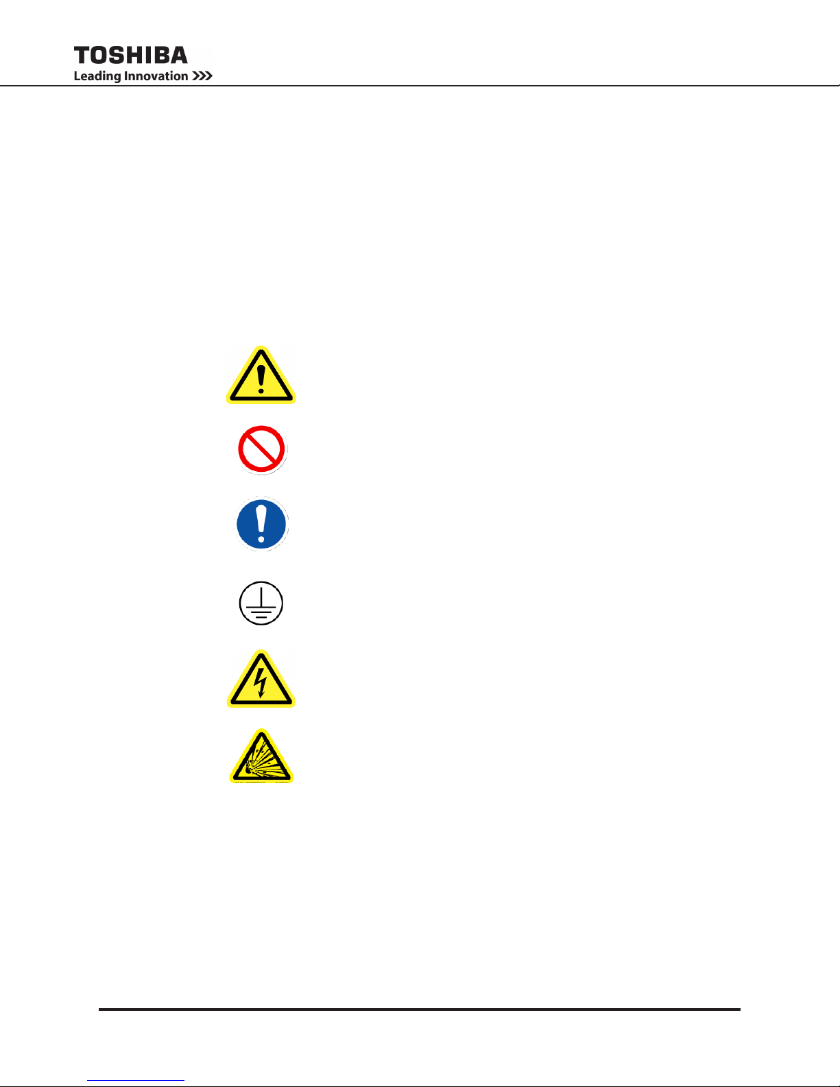
1.1 Symbols
The symbols listed below are used throughout this manual. When symbols are used in this manual they will
include important safety information that must be carefully followed.
Safety Alert Symbol indicates that a potential
personal injury hazard exists.
Prohibited Symbol indicates DO NOT take action.
Mandatory Symbol indicates that the following
instruction is required.
Ground Symbol indicates the location of the
equipment grounding conductor.
Electrical - Voltage & Shock Hazard Symbol
indicates parts inside may cause electric shock.
Explosion Hazard Symbol indicates parts may
explode.
1600XP Series Installation and Operation Manual
1
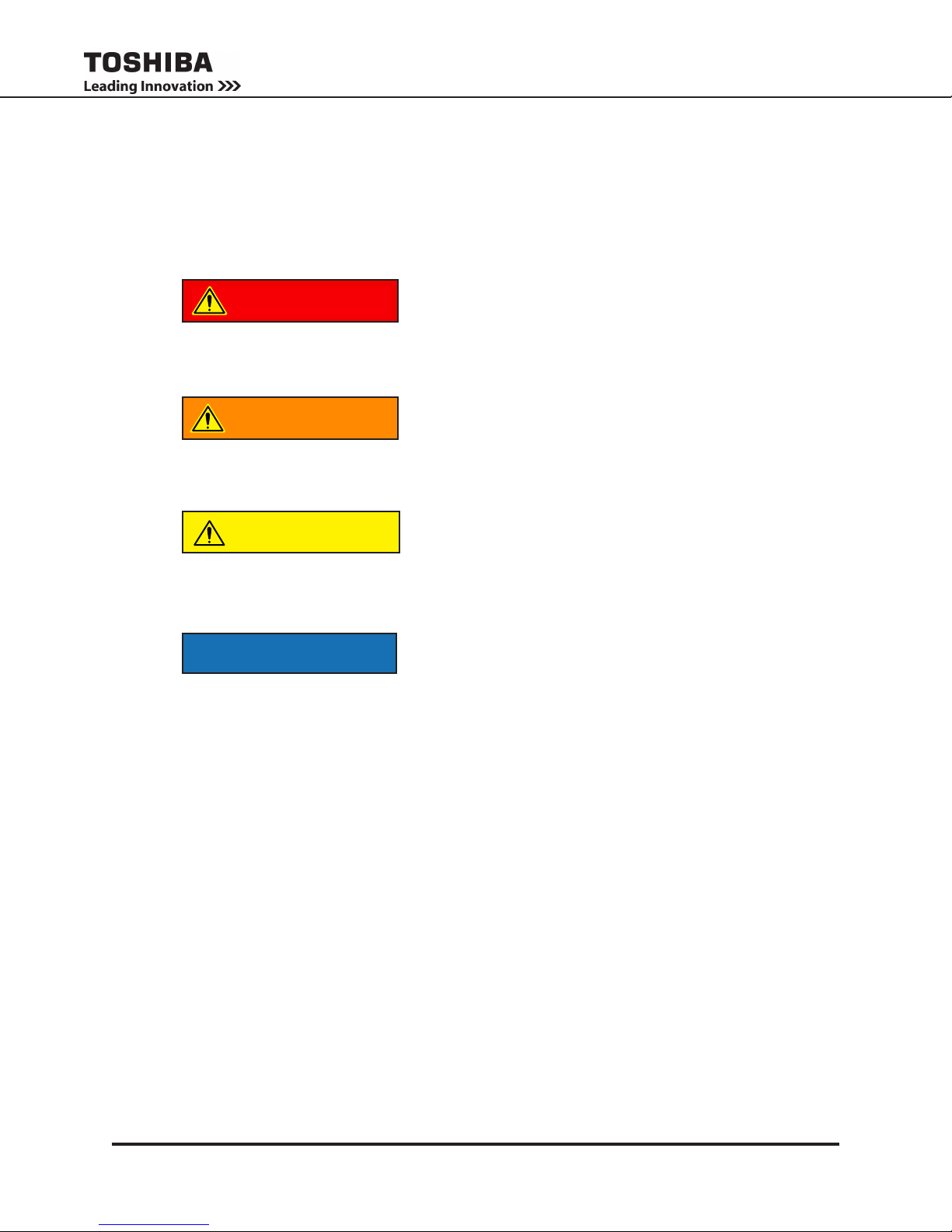
1.2 Signal Words
The signal words listed below are used throughout this manual. When the words DANGER, WARNING,
CAUTION and NOTICE are used in this manual they will include important safety information that must be
carefully followed.
The word DANGER in capital letters preceded by
DANGER
WARNING
CAUTION
the safety alert symbol indicates that an imminently
hazardous situation exists, and if not avoided
will result in loss of life or serious injury to
personnel.
The word WARNING in capital letters preceded by
the safety alert symbol indicates that a potentially
hazardous situation exists, and if not avoided
may result in loss of life or serious injury to
personnel.
The word CAUTION in capital letters preceded by
the safety alert symbol indicates that a potentially
hazardous situation exists, and if not avoided may
result in minor or moderate injury.
The word NOTICE in capital letters without the safety
NOTICE
alert symbol indicates a potentially hazardous
situation exists, and if not avoided may result in
equipment and property damage.
1.3 Regulatory Compliance Statement
FCC Class A Notice
This equipment has been tested and found to comply with the limits for a Class A digital device, pursuant
to Part 15 of the FCC Rules. These limits are designed to provide reasonable protection against harmful
interference when the equipment is operated in a commercial environment. This equipment generates,
uses, and can radiate radio frequency energy, and if it is not installed and used in accordance with the
instruction manual, it may cause harmful interference to radio communications. Operation of this equipment
in a residential area is likely to cause harmful interference, in which case the user will be required
to correct the interference at his own expense.
This device complies with Part 15 of the FCC Rules. Operation is subject to the following two conditions:
1. This device may not cause harmful interference.
2. This device must accept any interference received, including interference that may cause undesired
operation.
Notice: The FCC regulations provide that changes or modications made to this device that are not
approved by Toshiba International Corporation may void the authority granted to the user by the FCC to
operate this equipment.
EMC Directive Class A Note
This UPS is commercial in design and not intended for use at anytime in a Residential Environment.
2
1600XP Series Installation and Operation Manual

2. Equipment Warning Labels
PN 51727
EXTERNAL BATTERY CABINET
The battery cabinet must have
a nominal battery voltage of
288VDC.
WARNING
DANGER/ATTENTION
Risk of electrical s hock. Do not touch u ninsulated
battery ter minals. Batter ies shoul d be serviced b y
qua li fi ed service repre se ntative only. Miswiring of
battery c ould result in ele ctr cal shoc k a nd/or fire.
Risque de choc elec trique . Le circuit des batteries
nest pa s e so led e secteur. Le s cosses des batteries
peu ven t presenter une tension dangereu se part
rappor t a la terre. Verifier avan t de touch er.
DANGER
Batte ry fuse is al ways
l ive . R isk of ele ctr ica l
shock. Check fu se
voltage an d disconnec t
external batte ries
befo re changing fus e.
48518 SHEET
TYPEFORM
OUTPUT
UNINTERRUPTIBLE POWER SUPPLY
INPUT
LIST ED
POWER
SUPPLY
C US
EPO
14
15
16
17
EPO 1
EPO 2
RE M O TE
REMOTE
1
L1
L2 G
X1 X2
208V
120V
120V
20 8/2 40V
O UTPUT
I N PUT
N
X3
G
208V
USE CO PPER 90 C ONDUC TORS O NLY. REFER TO IN STRUCTION MANUAL REG ARDIN G TIG HTENING TORQ UE O F TERMINAL BLOCKS. FACTORY WIRED FOR 208V INPUT.
C OM
2
3
4
5
6 7
8
11
12
13
240V
240V
RE M O TE
JUMPER SEL ECTION
50802
WARNING
Th is un it con tains se aled lead a cid batt erie s.
La ck of preventative m ainte nan ce c ould r esult
in b atteries e xpl od ing a nd emittin g gass es an d/or
flam e. An nu al preven tati ve maintenance must be
pe rform ed by a n autho ri zed , trained technic ian .
WARNING
CRI TICAL F USE SIZ ING
Incorrect fu se replacem ent size
may res ult in fire or inadeq uate
equipm ent protection.
Repla ce only with s ame type
and rating of fuse.
49455 SHEET
PN 51727
EXTERNAL BATTERY CABINET
The battery cabinet must have
a nominal battery voltage of
288VDC.
WARNING
DANGER/ATTENTION
Risk of el ectrical shock. Do not touch u nin sulated
battery ter minals. Batteri es should be ser viced by
qualified s ervice repre se ntative only. Miswiring of
battery c ould result in ele ctrcal shoc k a nd/or fire.
Risque de choc elec trique . Le circuit des batteries
nest pa s e solede sec teur. Le s cosses des batteries
peuven t presenter une te nsion dange reuse part
rappor t a la terre. Verifier avan t de touch er.
DANGER
Batte ry fuse is always
liv e. R i sk of e lect ri cal
shock. Check fuse
voltage an d disconnec t
external batteries
before cha nging fuse.
48518 SHEET
TYPEFORM
OUTPUT
MFD. IN U.S.A. FROM FOREIGN AND DOMESTIC COMPONENTS
HOUSTON , TEXAS
UNINTERRUPTIBLE POWER SUPPLY
INPUT
SERIAL NO.
PN 6038 1
LISTED
POWER
SUPPLY
27E5
C US
EPO
14
15
16
17
EPO 1
EPO 2
RE M O TE
REMOTE
1
L1
L2 G
X1 X2
208V
120V
120V
208/ 240 V
O UTPUT
I NPUT
N
X3
G
208V
USE COPPER 90 CO NDUCTORS ONLY. REFER TO INSTRUCTIO N MANUAL REGARDIN G TIGHTENING TORQUE OF TERMINAL BLOCKS. FACTORY WIRED FOR 208V IN PUT.
C OM
2
3
4
5
6 7
8
11
12
13
240V
240V
RE M O TE
JUMPER SELECTION
50802
WA RNING
CR ITICAL FUSE SIZ ING
Incor rect fuse replacem ent size
may r esult in fire or inadequate
equ ipm ent protecti on.
Repla ce only with same t ype
and rating of fus e.
48518 SHEET
TYPEFORM
OUTPUT
MFD. IN U.S.A. FROM FOREIGN AND DOMESTIC COMPONENT S
HOUSTON , TEXAS
UNINTERRUPTIBLE POWER SUPPLY
INPUT
SERIAL NO.
PN 60381
LIST ED
POWER
SUPPLY
27E5
C US
EPO
14
15
16
17
EPO 1
EPO 2
RE M O TE
REMOTE
1
L1
L2 G
X1 X2
208V
120V
120V
20 8/2 40V
O UTPUT
I N PUT
N
X3
G
208V
USE CO PPER 90 C ONDUC TORS O NLY. REFER TO IN STRUCTION MANUAL REG ARDIN G TIG HTENING TORQ UE O F TERMINAL BLOCKS. FACTORY WIRED FOR 208V INPUT.
C OM
2
3
4
5
6 7
8
11
12
13
240V
240V
RE M O TE
JUMPER SEL ECTION
50802
The following pages show examples of warning labels that may be attached to either the interior or exterior of the UPS. Do not remove or cover any of the labels. If the labels are damaged or if additional
labels are required, contact your equipment representative for additional labels.
These labels are placed to provide useful information or to indicate an imminently hazardous situation
that may result in severe equipment/property damage, serious injury, or loss of life if instructions are
not followed.
P/N 63094 – External warning sign.
• Unit contains potentially dangerous voltages.
• Read the instruction manual before operating.
• There are no user serviceable parts inside.
Refer service to qualied personnel.
• Do not open the cover while power is applied,
or within ve minutes after removal of power.
• Potentially hazardous leakage current may
exist. Ensure the grounding is connected
before connecting the utility power.
1600XP Series Installation and Operation Manual
P/N 48518 – Battery terminals can deliver
dangerous electrical shock. Service by
qualied service representatives only.
P/N 49455 – UPS Batteries require an-
nual preventative maintenance. Failure to
perform regular maintenance could result in
batteries exploding, or emitting gasses or
ame.
P/N 49455 – Replace Fuse only
with one of same type and range.
Incorrect fuse size may result in
equipment damage.
3
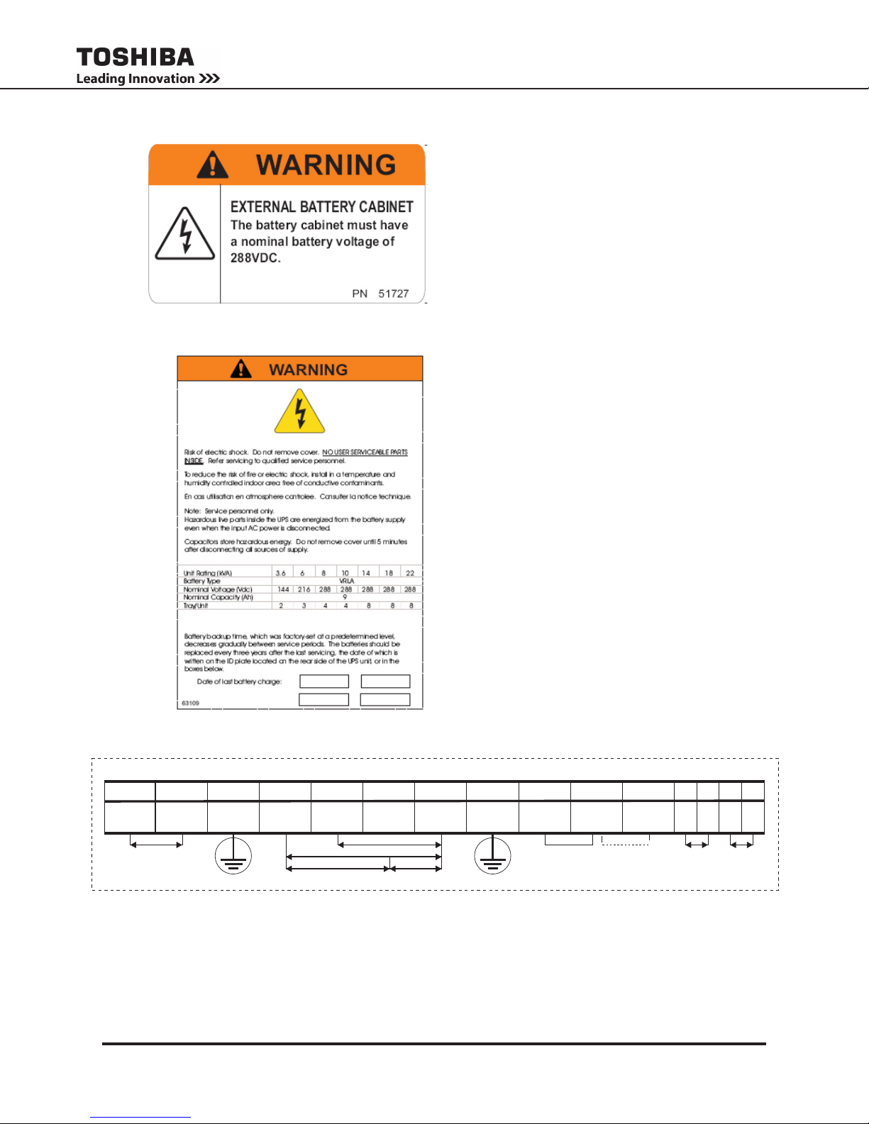
Battery Cabinet Warning Label.
* For reference only, DC voltage varies by
kVA size of the UPS.
P/N 63109 – There are no user-serviceable parts
behind cover. Wait ve minutes after disconnect-
ing the UPS to allow the internal capacitors to
discharge completely.
Date of last recorded battery change.
o
3
G
4
X1
1
L1
(L*)
USECOPPER90 CONDUCTORSONLY.REFERTOINSTRUCTIONMANUALREGARDINGTORQUEOFTERMINALBLOCKS.FACTORYWIREDFOR208VINPUT.
2
L2
(N*)
208/240V
INPUT
4
5
X2
120V
240V
OUTPUT
6
N
(0V*)
208V
120V
7
X3
8
G
P/N63093 - Power Terminal Label
1600XP Series Installation and Operation Manual
11
208V
12
COM
INPUTVOLTAGE
JUMPERSELECTION
14
13
240V
EPO1
EPO REMOTE
(*)FORSINGLEHOTWIRE
15
16
EPO2
REMOTE17REMOTE

3. Important Safety Instructions
This manual contains important instructions that should be followed during the installation and maintenance
of the UPS and its batteries.
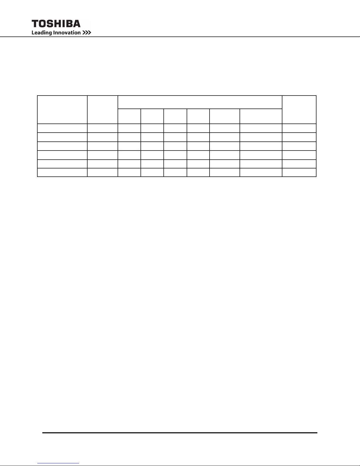
Hardwired UPS units are not equipped with an over-current protection device nor an output disconnect for
the AC output. A circuit breaker should be provided by the user between the UPS output and the load input.
This device should be rated as follows:
240VAC
RATING
* Ratings are for an 80% rated device.
The nominal battery voltages for these models are as follows:
BATTERY
VOLTAGE
Servicing of the batteries should only be performed by a qualied factory authorized representative who
is knowledgeable about batteries and the required precautions. Keep unauthorized personnel away from
batteries. To arrange for battery replacement, contact Toshiba Customer Support Center.
1. Turn off, lockout, and tagout all equipment before connecting the power wiring to the equipment or
when performing maintenance.
2. The maximum ambient operating temperature is 104 °F (40 °C).
3. Access panels should only be removed by authorized Toshiba eld Service personnel.
4. UPS servicing should be performed by qualied Toshiba representatives only.
5. Battery servicing should be performed by qualied Toshiba representatives only.
6. Contact your Toshiba authorized service center for battery replacement.
3.6 kVA 6 kVA 8 kVA 10 kVA 14 kVA 18 kVA 22 kVA
20 A 35 A 45 A 60 A 80 A 100 A 125 A
3.6 kVA 6 kVA 8 kVA 10 kVA 14 kVA 18 kVA 22 kVA
144 Vdc 216 Vdc 288 Vdc 288 Vdc 288 Vdc 288 Vdc 288 Vdc
1600XP Series Installation and Operation Manual
5
3.1 Qualied Personnel Only
Qualied personnel are those who have the skills and knowledge relating to the construction,
installation, operation, and maintenance of the electrical equipment and have received safety
training on the hazards involved (Refer to the latest edition of NFPA 70E for additional safety
requirements).
Qualied personnel shall:
1. Have read the entire operation manual.
2. Be trained and authorized to safely energize, de-energize, ground, lockout and tag circuits
and equipment, and clear faults in accordance with established safety practices.
3. Be trained in the proper care and use of protective equipment such as safety shoes, rubber
gloves, hard hats, safety glasses, face shields, ash clothing, etc., in accordance with
established safety practices.
4. Be trained in rendering rst aid.
5. Be knowledgeable about batteries and their required handling and maintenance precautions.
For further information about workplace safety visit www.osha.gov.
Misuse of this equipment may result in human injury
CAUTION
and equipment damage. In no event will Toshiba
Corporation be responsible or liable for either
indirect or consequential damage or injury that may
result from the misuse of this equipment.
CAUTION
CAUTION
To be performed by Qualied Personnel Only:
DO NOT open or mutilate the batteries. Released
electrolyte is harmful to the eyes and skin and could
also be toxic.
DO NOT dispose of the battery module in
a re. The batteries inside may explode.
1. Verify that the UPS is off and that the power is disconnected from the power source.
2. Remove watches, rings or other metal objects.
3. Use tools with insulated handles to prevent inadvertent shorts.
4. Wear rubber safety gloves and boots.
5. DO NOT place tools or any metal parts on top of batteries.
6. Determine if the battery is inadvertently grounded. If inadvertently grounded, remove source of
ground.
WARNING
Contact with any part of a grounded battery can result in
electrical shock.
The likelihood of shock will be reduced if such grounds are removed
prior to installation or maintenance.
6
1600XP Series Installation and Operation Manual

4. Inspection/Storage/Disposal
4.1 Inspection
Inspect for shipping damage upon receipt of the UPS. Use caution when removing the unit from the pallet.
Refer to labels or documentation attached to packing material.
4.2 Unpacking
Check the unit for loose, broken, bent or otherwise damaged parts. If damage has occurred during shipping,
keep all original crating and packing materials for return to the shipping agent. The warranty does not apply
to damage incurred during shipping. Ensure that the rated capacity and the model number specied on the
nameplate conform to the order specications.
4.3 Storage
During periods of non-use, the following guidelines are recommended for storage.
Storage Preparation
1. Power up the UPS and allow it to operate with no load for 24 hours to fully charge the
batteries.
2. Stop the unit (see Stop Operation on page 16).
3. Place the MCCB switch (see page 60 - 61 for location) in the Off position.
Storing Conditions
• For best results, store the UPS in the original shipping container and place on a wood
or metal pallet.
• Storage temperature: -4 – 104 °F (-20 – 40 °C).
• The optimum storage temperature is 70 °F (21 °C). A higher ambient temperature will
require recharging more frequently during storage.
Avoid storage locations that:
• Are subject to extreme temperature changes or high humidity.
• Are subject to high levels of dust or metal particles.
• Are subject to excessive vibration.
• Have inclined oor surfaces.
Storage Maintenance
• If stored at an ambient temperature less than 68 °F (20 °C), recharge the batteries every
9 months.
• If stored at an ambient temperature of 68 – 86 °F (20 – 30 °C), recharge the batteries
every 6 months.
• If stored at an ambient temperature of 86 – 104 °F (30 – 40 °C), recharge the batteries
every 3 months.
4.4 Disposal
Contact your local or state environmental agency for details on disposal of electrical components and
packaging in your particular area.
It is illegal to dump lead-acid batteries in landlls or dispose of improperly.
Please help our Earth by contacting the environmental protection agencies in your area, the battery
manufacturer, or call Toshiba toll-free at (877) 867-8773 for more information about recycling.
1600XP Series Installation and Operation Manual
7

5. Installation Precautions
fig 1
fig 2
1
2
3
Unpacking Instructions
P/N 48537
TYPEFORM
OUTPUT
MFD. IN U.S.A. FROM FOREIGN AND DOMESTIC COMPONENTS
HOUSTO N, TEXAS
UNINTERRUPTIBLE POWER SUPPLY
INPUT
SERIAL NO.
PN 6038 1
LISTED
POWER
SUPPLY
27E5
C US
EPO
14
15
16
17
EPO 1
EPO 2
RE M O TE
REMOTE
1
L1
L2 G
X1 X2
208V
120V
120V
208/ 240 V
O UTPUT
I NPUT
N
X3
G
208V
USE COPPER 90 C ONDUC TORS ON LY. REFER TO INSTRUCTION MANUAL REGARDING TIG HTENING TORQUE O F TERMINAL BLOCKS. FACTORY W IRED FOR 2 08V INPUT.
C OM
2
3
4
5
6 7
8
11
12
13
240V
240V
RE M O TE
JUMPER SELECTION
50802
NOTICE
1. Observe the following environmental restrictions:
• Install the unit in a well-ventilated location; allow at least 4 inches (10 cm) on all sides for air
ventilation and for maintenance.
• Install the unit where the ambient temperature is within the range specied on pages 53 - 58.
• DO NOT install the UPS in areas that are subject to high humidity.
• DO NOT install the UPS in areas that allow exposure to direct sunlight.
• DO NOT install the UPS in areas that allow exposure to high levels of airborne dust, metal
particles, or ammable gases.
• DO NOT install the UPS in areas near sources of electrical noise. Ensuring a proper earth ground
will reduce the effects of electrical noise and will reduce the potential for electrical shock.
• DO NOT install the UPS in areas that would allow uids or any foreign object to get inside the
2. UPS is intended for permanent installation only. Install the unit in a stable, level and upright position
3. Follow the instructions on the unpacking label afxed to the exterior of the UPS.
UPS.
that is free of excessive vibration.
4. Retain the shipping rails for use as permanent mounting of the UPS.
8
1600XP Series Installation and Operation Manual

5. Once the installation is complete, use a 3/4 inch wrench to screw down the UPS leveling feet located
next to the four casters, until the unit is no longer resting on the casters.
6. The UPS generates and can radiate radio-frequency energy during operation. Although RFI noise
lters are installed inside of the unit, there is no guarantee that the UPS will not inuence some
sensitive devices that are operating near by. If such interference is experienced, the UPS should be
installed farther away from the affected equipment and/or powered from a different source than that
of the affected equipment.
7. It is the responsibility of the installer of this equipment to provide a suitable disconnect for the Control
Panel supplying power to this equipment.
This disconnect must:
Be suitable for the Voltage and Full Load Ampere Rating of all downstream equipment supplied by
the Panel;
The supply disconnecting device shall be one of the following types:
• Switch-disconnector, with or without fuses, in accordance with IEC 60947-3, utilization
category AC-23B or DC-23B
• As above, except one that has an auxiliary contact that in all cases causes switching devices
to break the load circuit before the opening of the main contacts of the disconnector.
• A circuit breaker suitable as an isolation device per IEC 60947-2
• Any other switching device in accordance with an IEC product standard that also meets the
isolation requirements of IEC 60947-1 and is appropriate for on-load switching of motors or
other inductive loads;
Be approved for use as a disconnect for the country in which this equipment is installed.
Be provided with a Lock Out Tag Out capability in the Off (Down) position.
8. Allow 5 minutes after power is removed for internal capacitors to fully discharge before attempting
to service the unit.
9. The user should provide output over-current protection for hardwired UPS systems. See Specications
section on pages 19 and 22 for the device rating.
10. After ensuring that all power sources are turned off and isolated in accordance with established
lockout/tagout procedures, connect the power source wiring of the correct voltage to the input
terminals of the UPS.
11. The end user must supply suitable strain relief for the power cord and the cord must extend a
distance of 1/2 diameter beyond the clamp.
12. Connect the output terminals of the UPS to the load in line with local wiring regulations. Size the
branch circuit conductors in accordance with NEC Table 310.16.
1600XP Series Installation and Operation Manual
9
6. Conductor Routing and Grounding
1. Use separate metal conduits for routing the input power, output power, and control circuits.
2. Follow the wire size and tightening torque specications listed on page 13.
3. Always ground the unit to reduce the potential for electrical shock and to help reduce electrical
noise.
4. A separate ground cable should be run inside the conduit with the input power, output power, and
control circuits.
WARNING
THE METAL OF CONDUIT IS NOT AN ACCEPTABLE GROUND.
7. Operating Precautions
1. The UPS should not be powered up until the entire operation manual has been read.
2. The voltage of the input power source must be within the range of +10% to -30% of the rated
input voltage. The input frequency must be within the rated input frequency range. Voltages and
frequencies outside of the permissible range may activate the internal protection devices.
3. The UPS should not be used with a load that has a rated input that is greater than the rated output
of the UPS.
4. DO NOT use the UPS to provide power to motors that require high starting current or with motors
that require a long starting time, such as vacuum cleaners and machine tools (oversizing the UPS
for lock rotor current would be required).
5. DO NOT insert metal objects or combustible materials in the ventilation slots of the UPS.
6. DO NOT place, hang, or paste any objects on the exterior surfaces of the UPS.
7. The capacitors of the UPS maintain a residual charge for a while after turning the UPS off.
8. DO NOT attempt to disassemble, modify, or repair the UPS. Repairs and servicing should only be
performed by Toshiba Field Service personnel.
9. DO NOT remove any covers of the UPS when the power is on.
10. Turn the power on only after installing ALL of the covers.
11. If the UPS should emit smoke, produce an unusual odor, or make sound, turn the power off
immediately.
12. Changing/replacing the UPS Batteries should only be performed by Toshiba eld service personnel.
13. Warning signs should be placed on or near the load as a notication that the load is being powered
by the UPS.
14. Additional warnings and notications shall be posted at the equipment installation location as
deemed required by Qualied Personnel.
10
1600XP Series Installation and Operation Manual
8. UPS Connections
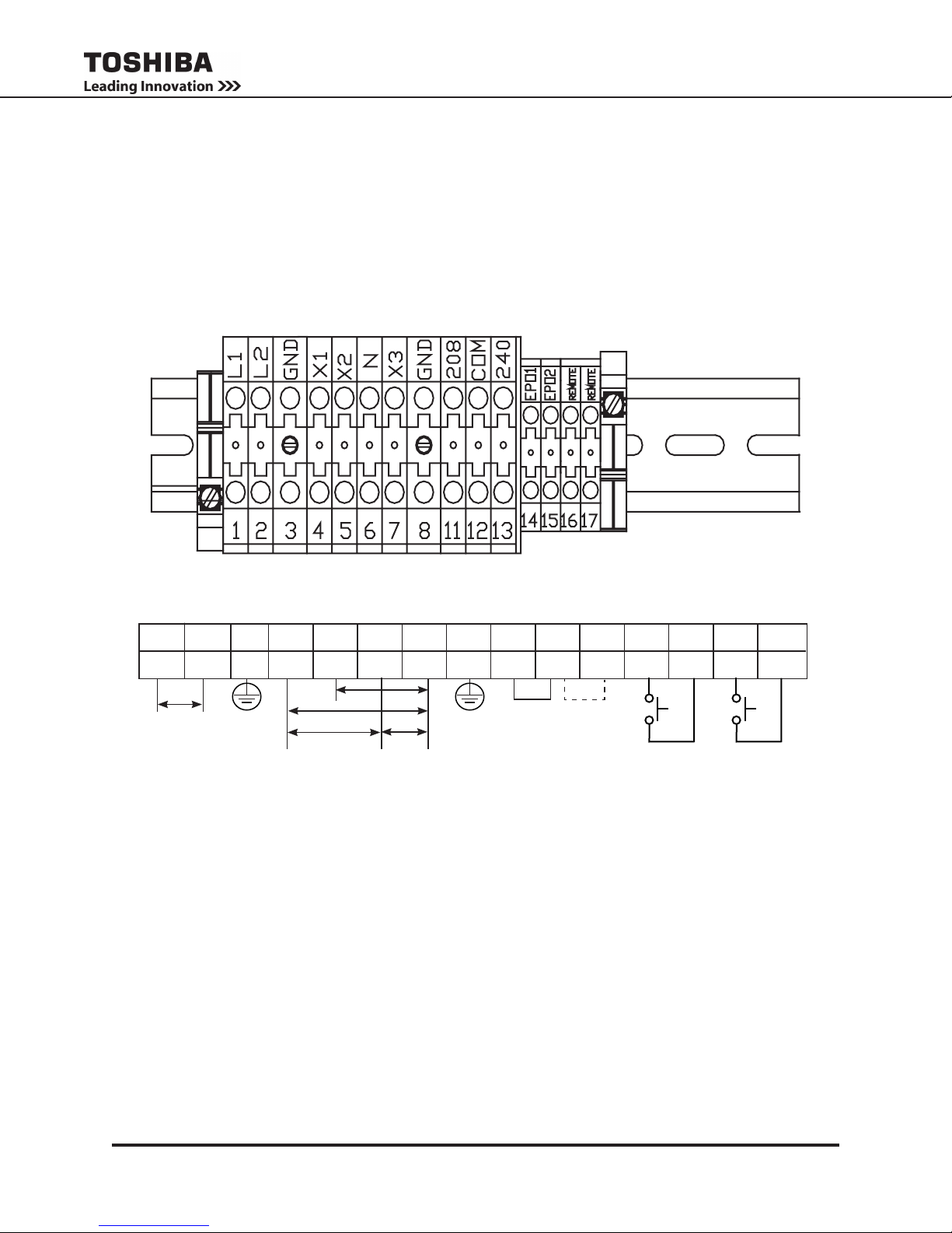
8.1 Terminal Block
The following illustration is a detail view of the terminal block and wiring connections used for 208/240
volt units (see pages 65-66 for terminal block location).
1
L1 (L*)
208/240 Vin
* – If only one input line is hot, connect hot line to terminal 1 (L), and connect the Neutral line to terminal 2 (N).
NOTE 1 – If AC input power is 208 Vac rated, short terminals 11 and 12 with a jumper wire. DO NOT jumper terminal 13 to 12 or
NOTE 2 – If AC input power is 240 Vac rated, short terminals 12 and 13 with a jumper wire. DO NOT jumper terminal 11 to 12 or
2
3
L2 (N*)
INPUT
11. Factory Setting is 208Vac. Use the jumper wire provided by Toshiba. DO NOT add any additional jumpers.
13. Use the jumper wire provided by Toshiba. DO NOT add any additional jumpers.
G X1 X2
120 V
N (0V)
208 V
240 V
120 V
OUTPUT
8765 114
208
12 1413 15
COM
208V
Jumper selection
See notes 1&2
240GX3
240V
EPO2EPO1
16 17
REMOTE1
REMOTE2
1600XP Series Installation and Operation Manual
11
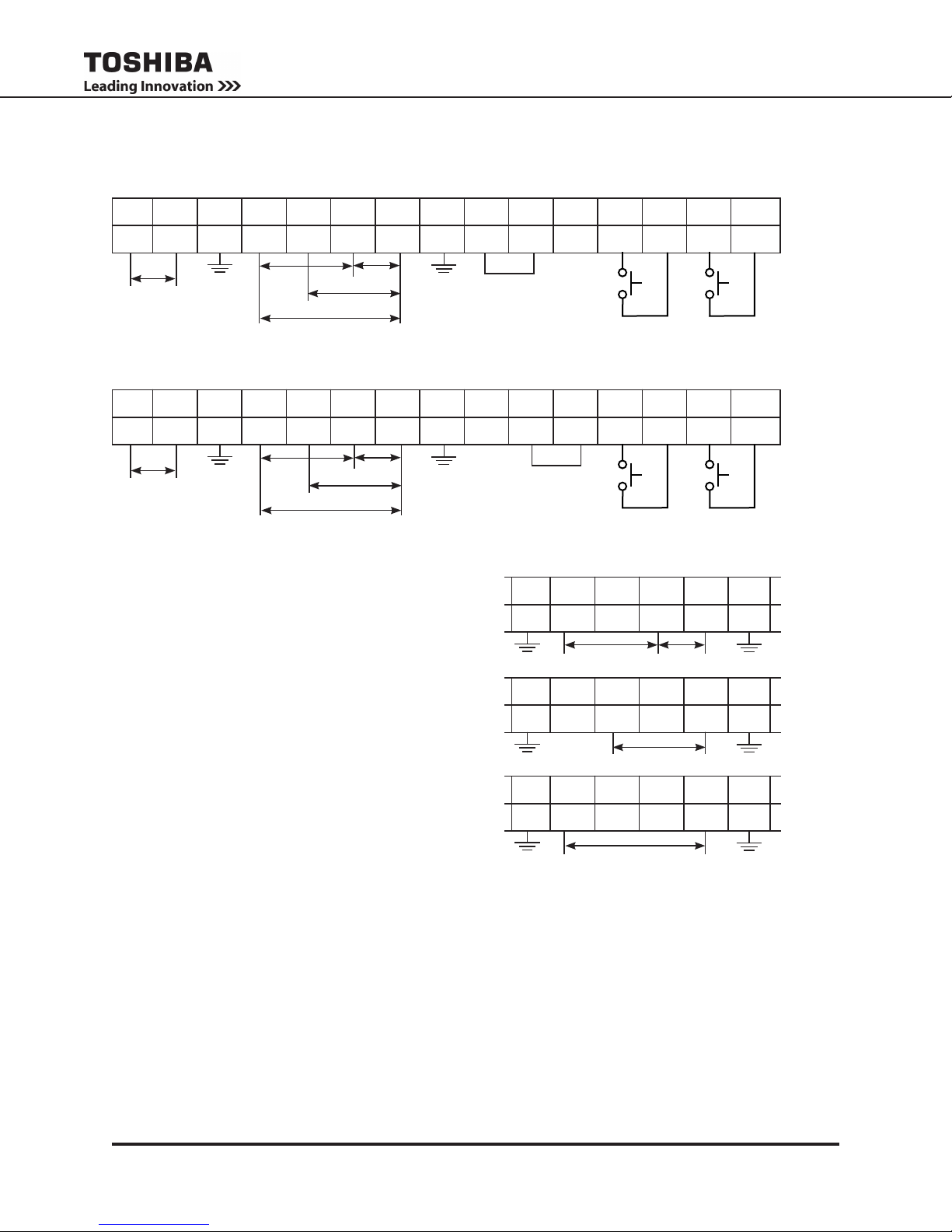
Input and Jumper wire/bus strip connection for:
208 Vin – Using provided jumper, connect terminals 11 – 12.
1
2 3
L2 G X1 X2 N
L1
208 Vin
120 V
120 V
208 V
240 V
8765 114
208
Jumper
240 Vin – Using provided jumper, connect terminals 13 – 12.
1
2 3
L2 G X1 X2 N
L1
240 Vin
120 V
120 V
208 V
240 V
8765 114
208
Output Cabling for:
120 Vout
Connect load across Terminals 4 – 6 or 6 – 7.
12 1413 15
COM
240GX3
EPO2EPO1
12 1413 15
COM
Jumper
240GX3
EPO2EPO1
3 87654
120 V
120 V
16 17
REMOTE1
16 17
REMOTE1
REMOTE2
REMOTE2
GX3G X1 X2 N
208 Vout
Connect load across terminals 5 – 7.
240 Vout
Connect load across terminals 4 – 7.
3 87654
GX3G X1 X2 N
208 Vout
3 87654
GX3G X1 X2 N
240 Vout
12
1600XP Series Installation and Operation Manual
8.2 Wire Size and Tightening Torque
Use the following table to select the recommended wire size and terminal lug tightening torque for I/O
wire connections. Use 90 °C copper conductors for all Input, Output, and Ground wiring.
Item
AC Input Lines 1 and 2 10 (8) 8 (8)
AC Output Lines 4, 5, and 7 12 (8) 10 (8)
AC Output Neutral 6 12 (8) 10 (8)
Ground 3 and 8 12 (8) 10 (8)
EPO Switch 14 and 15 16 16 16 16 16 16 9.0 (0.99)
Remote Switch 16 and 17 16 16 16 16 16 16 9.0 (0.99)
Note: Wire size is presented as the recommended size followed by a bold number in () that is the maximum wire size
the terminal block can accommodate. See page 64 for knock-out hole sizes on the back of each model.
Terminal
Number
3.6
kVA
6 kVA 8 kVA 10 kVA 14-18 kVA 22 kVA
Cable Size - AWG
8 (1/0) 6 (1/0)
8 (1/0) 6 (1/0)
8 (1/0) 6 (1/0) 4 (1/0))
8 (1/0) 6 (1/0) 4 (1/0))
4 (1/0) 1 (1/0) 14.2 (1.56)
4 (1/0) 1 (1/0) 14.2 (1.56)
1 (1/0) 14.2 (1.56)
1 (1/0) 14.2 (1.56)
Tightening
Torque
lb.-in. (N•m)
1600XP Series Installation and Operation Manual
13
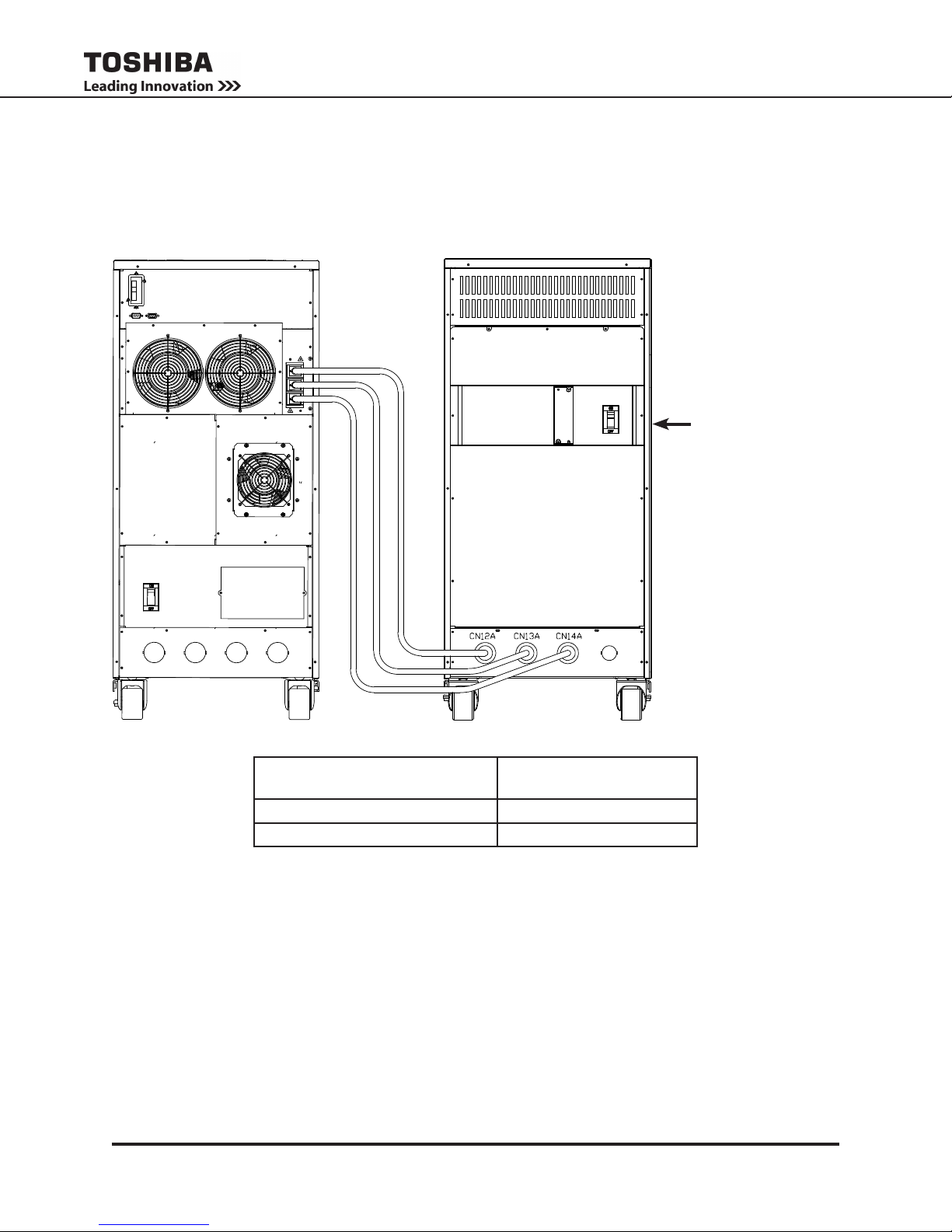
8.3 Optional Battery Cabinet Connections
Optional external battery cabinets can be used to extend the backup time of the UPS beyond that
available with the internal batteries. The external battery cabinets connect to the UPS via Anderson-style
connectors.
MCCB
(Battery Cabinet
Main Circuit Breaker)
3.6, 6 kVA 50 A
8, 10, 14, 18, 22 kVA 100 A
See the applicable battery cabinet manual for additional details.
14
UPS Model Battery Cabinet
MCCB Capacity
1600XP Series Installation and Operation Manual
9. Product Description
An uninterruptible power system (UPS) is a system that is installed between the commercial power and the
load equipment. The UPS provides steady AC output power during commercial power short-term blackouts
or brownouts. This power is provided for a sufcient amount of time so that the load can be shut down in an
orderly fashion. This prevents loss of data and possible damage to both hardware and software.
During normal operation, the UPS uses commercial AC power. It absorbs all of the high voltage spikes and
transients caused by switching and faults, and all of the common-mode and normal mode noise which is
associated with commercial AC power. The UPS converts it all to clean DC power. From this power, the
UPS charges its batteries and generates its own extremely high quality AC waveform output. The result of
this process is maximum power conditioning and regulation.
If the AC power supplied to the UPS drops below a specied voltage level, the unit’s batteries automatically
begin supplying power instead of receiving it. This insures that the loads connected to the UPS continue
to receive power with no interruption. When AC input power becomes available again, operation returns to
normal. The unit’s batteries begin to recharge so they will be ready for the next power interruption.
9.1 Application and Use
Toshiba 1600XP Series of On-Line UPS provides continuous computer-grade AC power in a compact, high
performance, and energy efcient unit. The UPS unit ensures safe and reliable operation of critical ofce
equipment. All units feature an audible alarm which sounds if the battery voltage drops below a specied
minimum during use. This is an additional aid to help protect valuable ofce data banks. All units allow for
computer interfacing.
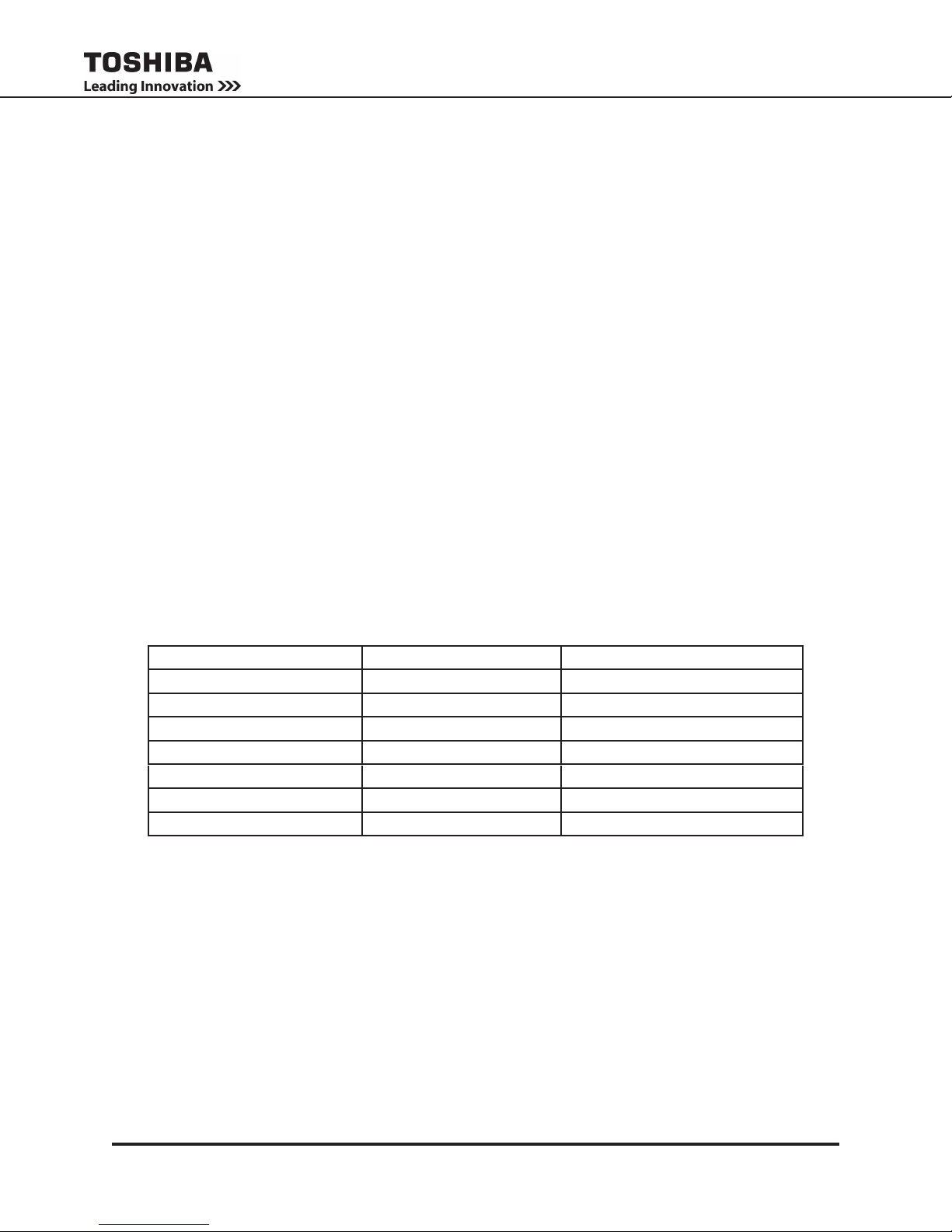
9.2 Output Rating
Toshiba 1600XP Series (208/240V) offers UPS models with the following capacities:
MODEL Output Capacity @ 240 V Output kW @ .85PF 240 V
UH3G2L036C61T 3.6 kVA 3.1 kW
UH3G2L060C61T 6 kVA 5.1 kW
UH3G2L080C61T 8 kVA 6.8 kW
UH3G2L100C61T 10 kVA 8.5 kW
UH3G2L140C61T 14 kVA 11.9 kW
UH3G2L180C61T 18 kVA 15.3 kW
UH3G2L220C61T* 22 kVA* 18.7 kW*
All models are RoHS compliant with the batteries being exempt from the directive.
*NOTE: Derate to 18.7 kVA (15.9 kW) for 50 Hz operation.
9.3 Power Backup
When an electrical power failure occurs, the UPS’s internal batteries automatically supply back-up power
to the load without interruption. For example, when used to support a computer, the UPS back-up assures
enough additional time to complete the activity and store the data. This allows an orderly shutdown after a
power failure has occurred.
9.4 Power Conditioning
When commercial power is present, the UPS supplies conditioned power to the load while maintaining its
batteries in a charged condition. The UPS protects against the normal, everyday pr oble ms ass ocia ted
with unreliable commercial power, including power sags, surges, signal interference, and spikes. This
protection keeps power-line problems from reaching your load, where they can cause equipment to operate
erratically, or damage software and hardware.
1600XP Series Installation and Operation Manual
15
10. Operating Modes
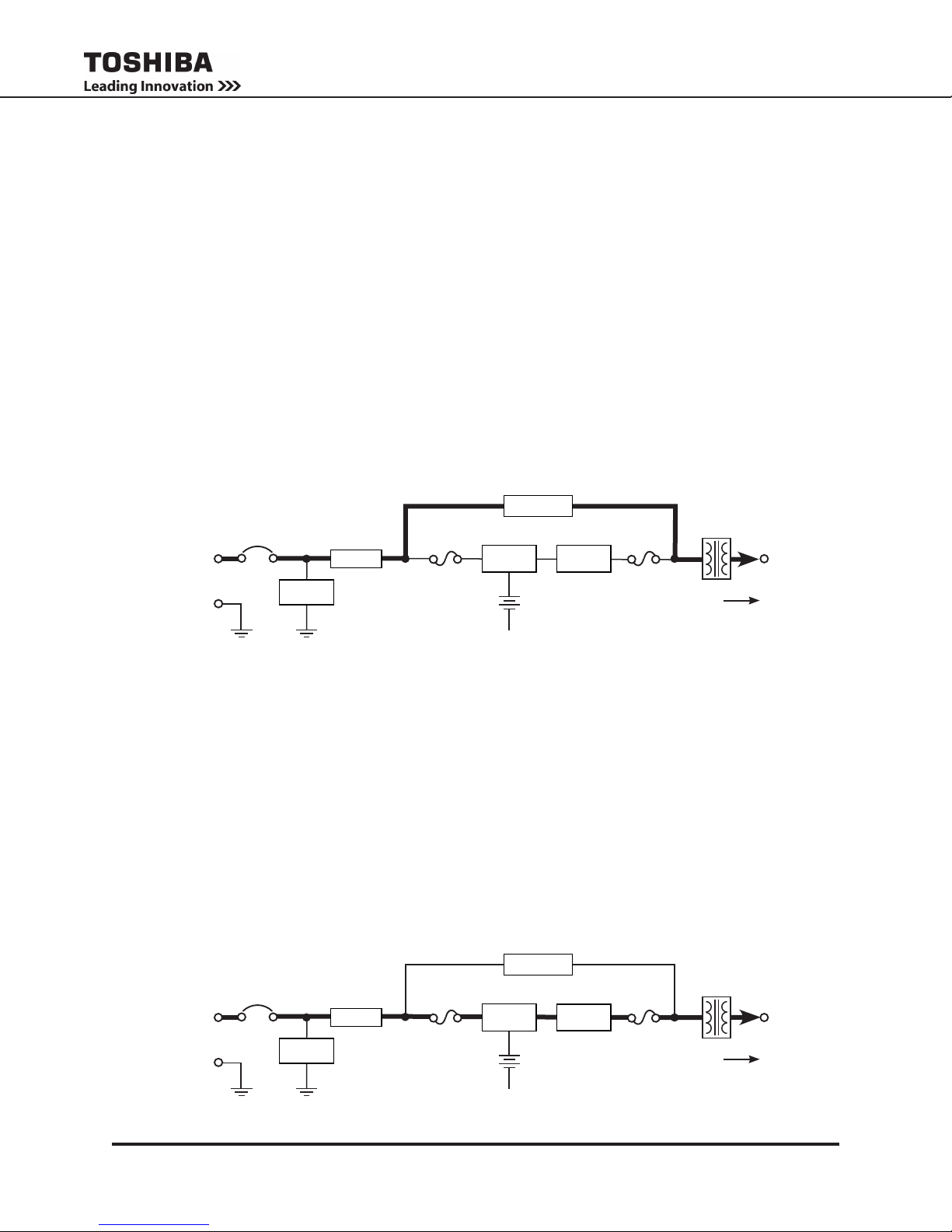
10.1 Static-Bypass (Stop operation)
If the UPS unit is severely overloaded or develops an internal fault, power ow is automatically switched
from the unit’s main circuit to the bypass circuit. Power ow through the bypass is shown in the following
illustration. This change-over occurs automatically in phase in less than one-quarter cycle of the input
waveform. The switching period is not long enough to cause interruptions to occur in most loads.
• If the power ow is transferred to the bypass circuit due to an internal fault the UPS will continue to
supply power to the load through the bypass and indicate a system fault message (see system fault
messages on pages 47–48).
• If the power ow is transferred to the bypass circuit due to an overload condition (see system warning
messages on pages 48–49), then the power ow will automatically transfer from the UPS’s bypass
circuit back to the inverter circuit after removing the overload if set to do so (AutoXfer parameter (Cmd
ID 660)).
Input
Power
MCCB
Surge
Absorber
Bypass
Input
Line Filter Inverter
Fuse
Batteries
*Static Switch
Rectier/
Chopper
+
–
Negative Bus
* Switches are
solid state
devices.
Output
Fuse
Isolation
Transformer
Power Flow
Output
Power
POWER FLOW IN BYPASS FOR ALL MODELS
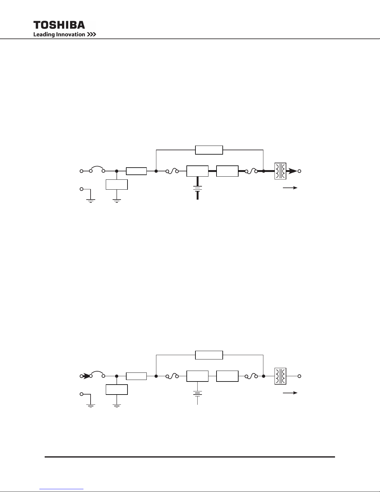
10.2 On-Line (Run operation)
The following illustration shows circuit power ow when the UPS is operating normally in the On-Line
mode. The UPS rectier, including a boost chopper circuit, converts AC input power to DC power. The
boost chopper circuit maintains a constant voltage, with current limiting, for charging the batteries.
The inverter section generates a high quality sinusoidal output voltage. The unit’s batteries are always
maintained in a constantly charged state when the UPS is in the run operation mode.
Input
Power
MCCB
Surge
Absorber
POWER FLOW IN ON-LINE MODE FOR ALL MODELS
16
Bypass
Input
Line Filter Inverter
Fuse
Batteries
*Static Switch
Rectier/
Chopper
+
–
Negative Bus
* Switches are
solid state
devices.
1600XP Series Installation and Operation Manual
Output
Fuse
Isolation
Transformer
Power Flow
Output
Power
10.3 Battery Backup (On batteries)
The following illustration shows power ow during the battery backup mode. When commercial AC power
failures occur, the UPS’s batteries instantly begin supplying DC voltage to the UPS’s main inverter circuit.
This circuit changes (inverts) the DC power into AC power. The AC power is available at the output of the
unit.
This back-up process will continue until the UPS’s battery voltage drops below a specic minimum level.
When this occurs, the batteries will stop supplying power to the load. This minimum level is the rated
minimum voltage (Vmin). The rated battery voltage chart on page 19 shows (Vmin). The battery backup
time and discharge process is explained on page 19.
Input
Power
MCCB
Surge
Absorber
Line Filter
Input
Fuse
Bypass
Batteries
*Static Switch
Rectier/
Chopper
+
–
Negative Bus
Inverter
* Switches are
solid state
devices.
Output
Fuse
Isolation
Transformer
Power Flow
Output
Power
POWER FLOW IN BATTERY BACKUP FOR ALL MODELS
10.4 EPO (Emergency Power Off) Function
These units are equipped with terminals for receiving an emergency power-off (EPO) command via a
closed-contact switch at a remote location (see Terminal Block Details on page 11 and terminal block
location on pages 60-61). This safety feature enables quick shut-down of the UPS’s AC input breaker,
output and battery circuits.
Usually the emergency power off switch is installed in a central location that is easily accessible to
personnel concerned with the operation of the UPS unit and the load equipment connected to it. The EPO
function is initiated by pressing the switch to the closed (shutdown) position.
The effect of using the EPO switch is the same whether the UPS unit is in AC input mode, battery backup
mode, or the circuit bypass mode. The following gure shows the UPS condition after application of the
EPO switch.
Input
Power
MCCB
Surge
Absorber
Line Filter Inverter
POWER FLOW AFTER AN EPO COMMAND FOR ALL MODELS
1600XP Series Installation and Operation Manual
Input
Fuse
Bypass
Batteries
Negative Bus
*Static Switch
Rectier/
Chopper
+
–
* Switches are
solid state
devices.
Output
Fuse
Isolation
Transformer
Power Flow
Output
Power
17
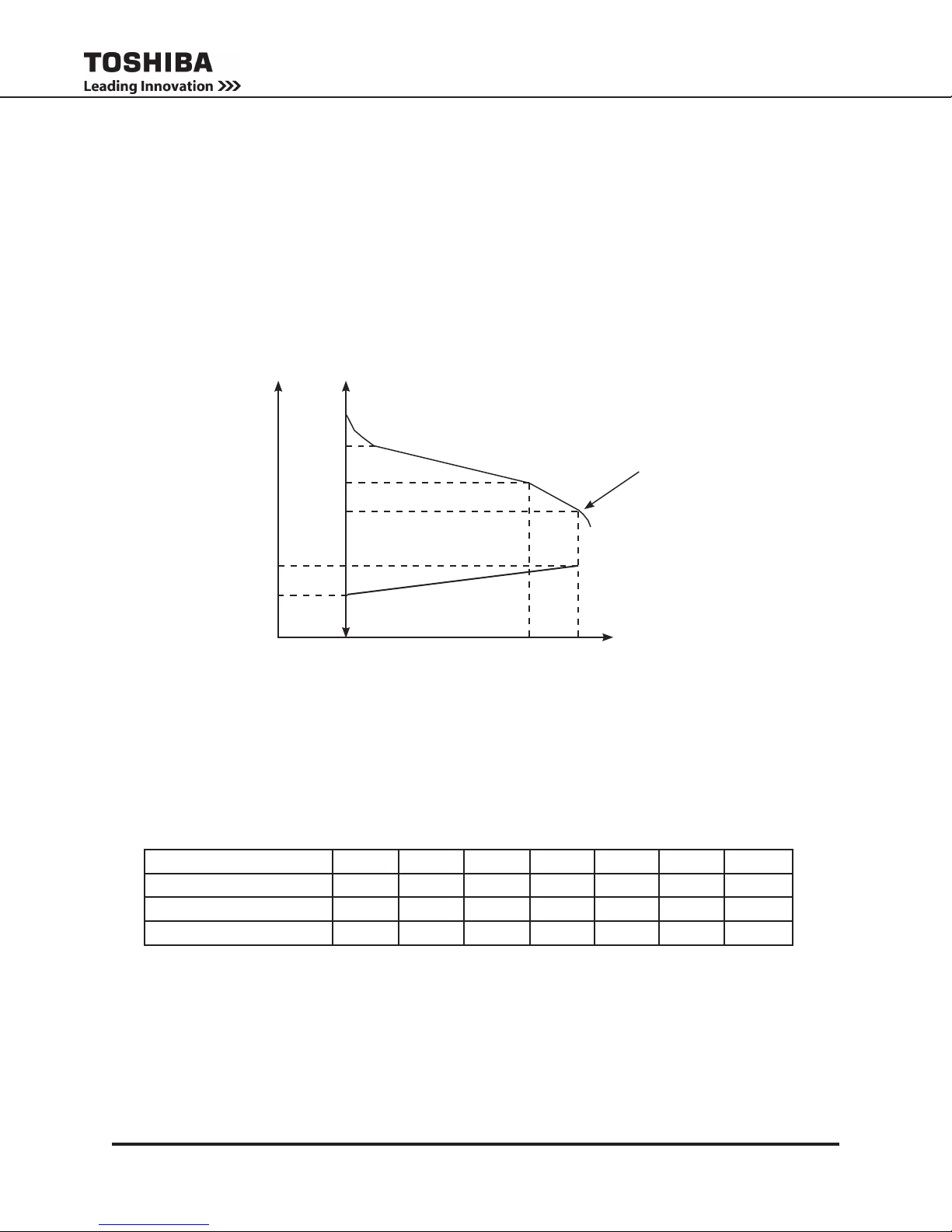
10.5 Battery Backup Time and Discharge Process
The UPS batteries provide approximately 5-7 minutes of back-up time depending on the 1600XP unit kVA
rating. These times are valid when the unit is operating under full load and at the rated power factor. The
exact length of these times will depend on the UPS model used, condition of the batteries, amount and
type of load, temperature and other variables. See battery backup time in ‘UPS Specications’ beginning
on page 53.
The following illustration graphically shows the battery discharge process at full load conditions.
CURRENT VOLTAGE
V
NOM
SHUTDOWN
I
MAX
I
MIN
V
LOW
V
MIN
100% 20% 0%
BATTERY CAPACITY
10.6 Battery Low Voltage Tolerances
Excessive discharge will cause the UPS battery voltage to drop. The chart shown below lists the voltage
level at which each UPS low-voltage alarm will sound and at what level the low-voltage condition will
cause the unit to automatically shut down.
UPS Capacity
Nominal voltage (Vnom)
Alarm voltage (Vlow)
Shutdown voltage (Vmin)
3.6 kVA 6 kVA 8 kVA 10 kVA 14 kVA 18 kVA 22 kVA
144 Vdc 216 Vdc 288 Vdc 288 Vdc 288 Vdc 288 Vdc 288 Vdc
130 Vdc 192 Vdc 246 Vdc 246 Vdc 246 Vdc 246 Vdc 246 Vdc
114 Vdc 170 Vdc 227 Vdc 227 Vdc 227 Vdc 227 Vdc 227 Vdc
18
1600XP Series Installation and Operation Manual
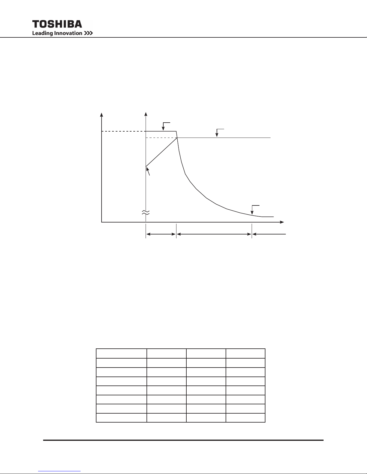
10.7 Battery Recharging
The illustration below shows a graphical representation of the UPS battery recharge process after a full
discharge.
CURRENT VOLTAGE
I
CHARGE
V
MAX
V
MIN
0 0
DISCHARGE
SHUT-OFF
POINT
PERIOD 1
CHARGING
CURRENT
PERIOD 2
BATTERY
CHARGE
VOLTAGE
FULLY
CHARGED
TIME
PERIOD 3
The recharge process usually consists of three periods. During the rst period, the current is maintained
at approximately 1 ampere. This current limit is the maximum value that can be used to charge the
batteries (for minimal recharge time) while assuring safety and long battery life. In the second period,
constant-voltage control starts and current gradually decreases as the batteries charge to their normal
fully charged state. In the third period, a slight trickle current continues to ow into the batteries to keep
them fully charged and oating at the normal Vdc level. A full recharge usually requires 24 hours (90%
recharge in 12 hours) after a complete discharge.
The following chart shows the rated maximum and minimum battery voltages and the charge current for
each of the sizes.
Model Vmax Vmin Icharge
3.6 kVA 163 V 114 V 1.0 A
6 kVA 245.7 V 170 V 1.0 A
8 kVA 327 V 227 V 1.0 A
10 kVA 327 V 227 V 1.0 A
14 kVA 327 V 227 V 1.0 A
18 kVA 327 V 227 V 1.0 A
22 kVA 327 V 227 V 1.0 A
1600XP Series Installation and Operation Manual
RATED BATTERY VOLTAGES
19

11. Operating the UPS
The 1600XP should be installed by a certied electrician. Once installed, the 1600XP is designed to be
operated by any user. Anyone not familiar with this UPS should read the manual before attempting to
operate it.
11.1 Initial Startup (First Power-Up)
The rst time the UPS is activated after being shipped from the factory, these parameters need to be
set by the customer for site specic ratings. Input Rated Voltage, Output Rated Voltage, UPS Date, and
UPS Time.
The input frequency defaults to 60 Hz.
The rst screen displayed during the initial startup sequence requires the operator to select the nominal
Input Voltage. Select from 208V, 230V, or 240V, and press the Write key.
If the command has been accepted, the word “Successful” will appear at the bottom left side of the
display.
1. Repeat the process in step 1 in selecting the Rated Output Voltage.
2. Use the keypad to type in the current date in the format: Mon 10/05/2009 and press Write.
3. Use the keypad to type in the current time in 12 hour format: 12:15 PM and press Write.
4. The Main screen is now displayed. Verify the UPS is in BYPASS mode. The mode (lower right side
of the display) should display Bypass. If it does not display Bypass, press and momentarily hold
the STOP button on the Main display.
5. With the UPS in bypass mode, cycle power to the UPS as follows:
• At the rear of the UPS switch the main circuit breaker MCCB to OFF.
• Leave the UPS off until the DC bus is safely discharged (approximately 5-10 minutes).
• Restart the UPS by switching the main circuit breaker ON.
The table below summarizes the initialization parameters:
ID Command Options
111 Rated Vin Select from 208V, 230V, or 240V, and press Write.
215 Rated Vout Select from 208V, 230V, or 240V, and press Write.
634 UPS Date Input the date in this format: Mon 10/05/2009 and press Write.
635 UPS Time Input the current time in 12 hour format: 12:15 PM and press Write.
20
1600XP Series Installation and Operation Manual
 Loading...