

Toshiba UF1A1A015C6(T), UF1A1A024C6T, UF1A1A015C6, UF1A1A024C6 User Manual
TOSHIBA
www . ElectricalPartManuals . com
TOSHIBA
User Manual
Uninterruptible Power System
1700 Series
Single Phase – 1.5/2.0/2.4 kVA
1

TOSHIBA
www . ElectricalPartManuals . com
2
TOSHIBA
www . ElectricalPartManuals . com
IMPORTANT NOTICE
The instructions contained in this manual are not intended to cover all of
the details or variations in equipment, nor to provide for every possible
contingency to be met in connection with installation, operation, or
maintenance. Should further information be desired or should particular
problems arise which are not covered sufficiently for the purchaser's
purposes, the matter should be referred to the local Toshiba sales office.
The contents of this instruction manual shall not become a part of or
modify any prior or existing agreement, commitment, or relationship. The
sales contract contains the entire obligation of Toshiba International
Corporation's UPS Division. The warranty contained in the contract
between the parties is the sole warranty of Toshiba International
Corporation's UPS Division and any statements contained herein do not
create new warranties or modify the existing warranty.
Any electrical or mechanical modifications to this equipment,
without prior written consent of Toshiba International Corporation
will void all warranties and may void UL/CUL listing. Unauthorized
modifications also can result in personal injury, death, or
destruction of the equipment.
UNINTERRUPTIBLE POWER SUPPLY
If additional information or technical assistance is required beyond what
is included in this manual contact Toshiba’s marketing department by
calling toll free (800) 231-1412, by e-mail at toshibaups@tic.toshiba.com
or write to: Toshiba International Corporation, 13131 W. Little York
Road, Houston, TX 77041-9990.
Please complete the following information for your records and to remain
within this equipment manual:
Model Number:
Serial Number:
Date of Installation:
Inspected By:
October, 2003
Part no. 50124-001
,
3
TOSHIBA
www . ElectricalPartManuals . com
TABLE OF CONTENTS
SECTION PAGE
Disclaimer................................................................................................ 3
Table of Contents.................................................................................... 4
General Safety Instructions ...................................................................5
Important Safety Instructions.............................................................6-7
Inspection/Installation............................................................................8
Inspection of the New UPS..........................................................................................8
Installation Precautions ...............................................................................................8
Operating Precautions.................................................................................................8
External Layout....................................................................................... 9
Electronics Module......................................................................................................9
Battery Modules........................................................................................................10
UPS Connections.................................................................................. 10
Standard Module Connections..................................................................................10
Operating the UPS ................................................................................ 12
Display Panel Layout.................................................................................................12
Starting the UPS System...........................................................................................12
Starting when AC Power is Available.........................................................................12
Starting on DC Power................................................................................................13
Stopping the UPS......................................................................................................13
UPS Display Status and Operating Condition............................................................14
System Reset............................................................................................................16
Battery Backup Ti me.................................................................................................16
Load Shed Function..................................................................................................16
Battery Recharge Time .............................................................................................16
Battery Check Function.............................................................................................17
The Function Control Button......................................................................................17
Fixed Frequency Mode..............................................................................................20
Adding Additional Battery Modules............................................................................20
Other Option Modules...............................................................................................21
Communication Interface..................................................................... 22
Remote Contacts......................................................................................................22
RS-232C...................................................................................................................22
Option Card Slot........................................................................................................22
Troubleshooting.................................................................................... 22
Warning/Fault Modes................................................................................................22
Warnings...........................................................................................................23
Faults................................................................................................................26
Storage of UPS Equipment .................................................................. 29
Disposal....................................................................................................................29
Preventative Maintenance/Parts Replacement.................................. 30
Preventative Maintenance.........................................................................................30
Parts Replacement....................................................................................................30
Appendices............................................................................................ 31
A: Specifications......................................................................................................31
B: Fan Speed Control..............................................................................................32
C: System Overload Rating......................................................................................33
D: Parallel Operation...............................................................................................34
E: Bypass Undervoltage / Overvoltage ....................................................................35
F: Unit Configuration Options ..................................................................................36
G: Weights and Dimensions.....................................................................................37
Warranty Policy..................................................................................... 38
4
TOSHIBA
www . ElectricalPartManuals . com
GENERAL SAFETY INSTRUCTIONS
Warnings in this manual appear in two different ways:
1) Danger warnings - The danger warning symbol is an exclamation mark
enclosed in a triangle that precedes the large bold letters spelling the
word "DANGER". The Danger warning symbol is used to indicate
situations, locations, and conditions that exist and can cause serious
injury or death:
DANGER
2) Caution warnings - The caution warning symbol is an exclamation mark
enclosed in a triangle that precedes the large bold letters spelling the
word "CAUTION". The Caution warning symbol is used to indicate
situations and conditions that can cau se opera tor injury and/ or
equipment damage:
CAUTION
Other warning symbols may appear along with the Danger and Caution
symbol and are used to specify special hazards. These warnings
describe particular areas where special care and/or procedures are
required in order to prevent serious injury and possible death:
1) Electrical warnings - The electrical warning symbol is a lightning bolt
mark enclosed in a triangle. The electrical warning
symbol is used to indicate high voltage locations and
conditions that may cause serious injury or death if
the proper precautions are not observed.
2) Explosion warnings - The explosion warning symbol is an explosion
mark enclosed in a triangle. The explosion warning symbol is
used to indicate locations and conditions where molten,
exploding parts may cause serious injury or death if the
proper precautions are not observed.
5
TOSHIBA
www . ElectricalPartManuals . com
IMPORTANT SAFETY INSTRUCTIONS
SAVE THESE INSTRUCTIONS. This manual
contains important instructions for the 1.5 and 2.4kVA 1700 Series
Toshiba UPS. These instructions should be followed during the
installation and maintenance of the UPS and its batteries.
¾ The maximum ambient temperature in which this UPS unit should
be operated or stored is 104 °F (40 °C).
¾ The batteries for the Toshiba 1700 Series 1.5 and 2.4kVA UPS are
housed in a self-contained battery module. This module should not
be opened under any circumstances. To replace the batteries, a
new module should be obtained from your local Toshiba
representative, or contact the Toshiba UPS marketing department
toll-free at (800) 231-1412.
¾ When changing battery packs, be sure to use the proper model unit.
CAUTION
DANGER
CAUTION
CAUTION
CAUTION
Misuse of this equipment could result in human
injury and equipment damage. In no event will
Toshiba Corporation be responsible or liable for
either indirect or consequential damage or injury
that may result from the use of this equipment.
Do not dispose of the battery module
in a fire. The batteries inside may
explode.
Do not open or mutilate the battery module.
Released electrolyte is harmful to the eyes and
skin, and could be toxic.
This unit contains sealed lead acid batteries.
Lack of preventative maintenance could result in
batteries exploding and emitting gasses and/or
flame.
Failure to replace the battery pack in
accordance to the maintenance schedule may
cause the batteries inside to crack, possibly
releasing electrolytes from the battery, and
resulting in secondary faults s uch as odor,
smoke and fire.
6
TOSHIBA
www . ElectricalPartManuals . com
INSTRUCTIONS IMPORTANTES
CONCERNANT LA SÉCURITÉ
CONSERVER CES INSTRUCTIONS.
contient des instructions importantes concernant la sécurit.
ATTENTION
ATTENTION
ATTENTION
Une batterie peut présenter un risque de
choc électrique, de brûlure par transfert
d’énergie.
Pour le remplacement, utiliser le même
nombre de batteries du modèle suivant.
L’élimination des batteries est
réglementée. Consulter les codes
locaux à cet effet.
Cette notice
7

TOSHIBA
www . ElectricalPartManuals . com
Inspection/Installation
Inspection of the New UPS Equipment
Upon receipt of the UPS, a careful inspection for shipping damage
should be made.
After Unpacking:
1) Check the unit for loose, broken, bent or otherwise damaged
parts. If damage has occurred during shipment, keep all original
packing materials for return to shipping agent. Warranty will not
apply to units damaged during shipment.
2) Check to see that the rated capacity and the model number
specified on the nameplate conform to the order specifications.
Installation Precautions
1) Install the unit in a well ventilated location; allow at least 10 cm
(4 inches) on all sides for air ventilation and for maintenance.
2) Install the unit in a stable, level, and upright position that is free
of vibration.
3) Install the unit where the ambient temperature is between 32°
and 104°F (0° and 40°C).
4) Do not install the UPS in areas that are subject to high humidity.
5) Do not install the UPS in a location that will cause direct sunlight
to shine on the unit.
6) Do not install the UPS in areas that are subject to contamination
such as high levels of airborne dust, metal particles, or
flammable gas.
7) Avoid installation near sources of electrical noise. Always make
sure that the unit earth ground is intact to prevent electrical
shock and to help reduce electrical noise.
8) Do not install where water or any foreign object may get inside
the UPS.
9) This UPS generates and can radiate radio-frequency energy
during operation. Although RFI noise filters are installed inside
the unit there is no guarantee that the UPS will not influence
some sensitive devices which are operating close by. If such
interference is experienced, the UPS should be installed farther
away from the affected equipment and/or powered from a
different source than that of the affected equipment.
Operating Precautions
1) The UPS should not be powered up until this entire manual has
been reviewed.
CAUTION
CAUTION
8
TOSHIBA
www . ElectricalPartManuals . com
2) The input power source voltage must be within +10% to -30% of
the rated input voltage. The input frequency must be within the
rated input frequency range. Voltages and frequencies outside of
the permissible tolerance range may cause internal protection
devices to activate.
3) The UPS should not be used with a load whose rated input is
greater than the rated UPS output.
4) Do not use the UPS to provide power to motors that require high
starting current or that require a long starting time such as
vacuum cleaners and machine tools (unless appropriate sizing is
done by a Toshiba applications engineer, or other qualified
personnel).
5) Do not insert metal objects or combustible materials in the unit's
ventilation slots.
6) Do not place, hang, or paste any objects on the top or on the
exterior surfaces of the UPS.
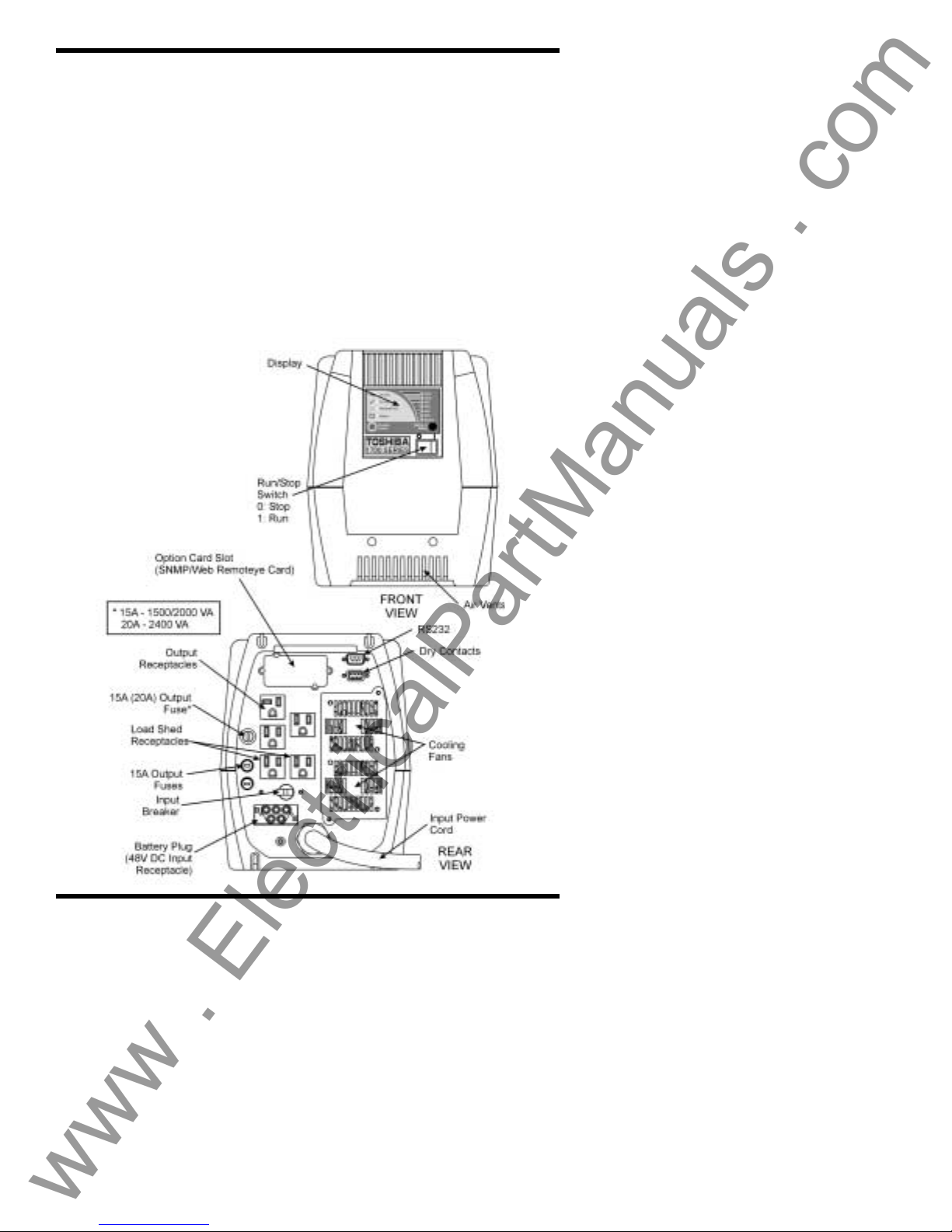
External Layout
Electronics Module
9
Figure 1
Electronics
Module
Layout
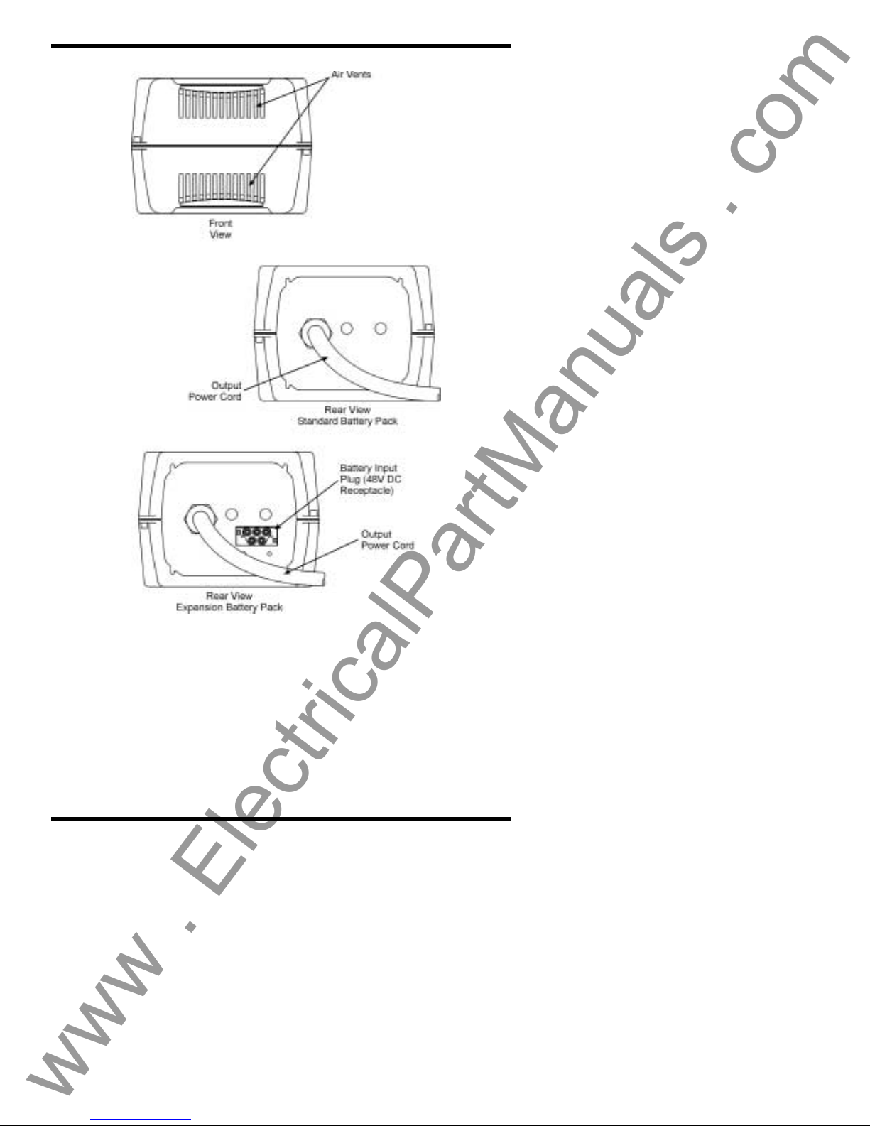
Battery Module
www . ElectricalPartManuals . com
TOSHIBA
Figure 2
Battery Module Layout
UPS Connections
Standard Module Connections
The illustration on the following page shows the proper assembly of
the two modules that make up the standard unit. If additional battery
modules are being installed with the standard unit see page 20. For
all other option modules see page 21.
Note: No more than three modules should be stacked on top of each
other for any configuration.
10
TOSHIBA
www . ElectricalPartManuals . com
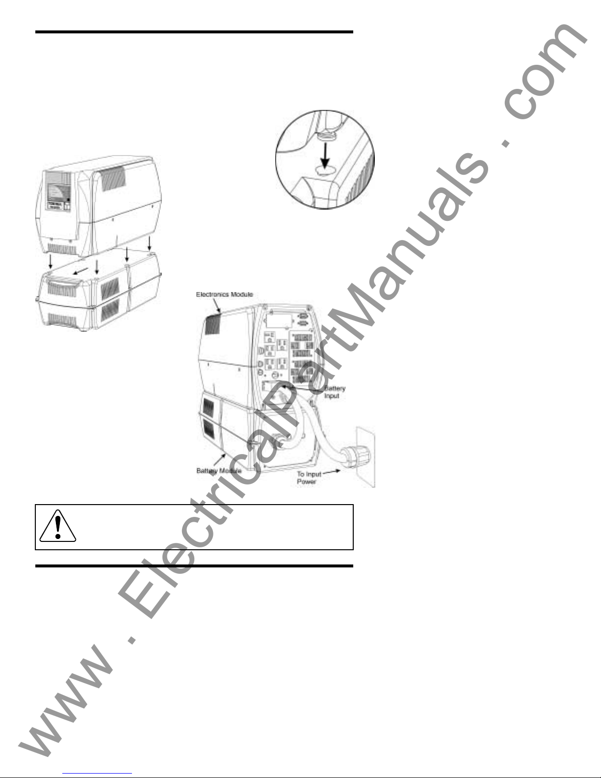
Standard Module Connections (cont’d)
If two modules are to be stacked on top of each other, they should
be interlocked to reduce the chances of the top module being
knocked over. Modules do not have to be stacked for the system to
operate. The following steps will guide the user through the process
of assembling and connecting the modules.
Step 1: Place the electronics module on top of
the battery module so that the six round feet on
the bottom of the electronics module fit into the
matching keyhole slots on the top of the battery
module.
Step 2: Slide the
upper unit forward.
This will cause the
two units to lock
together. In order to unlock the units, lift
up on the top module, and slide it back.
This will release the interlock (figure 3).
Step 3: Connect the input power cord
(figure 4) to the AC power source. If no
AC power source is available go to step 5.
Figure 3
Module Interlock
Step 4: Switch the input
breaker to the on position
(figure 1, page 9).
Step 5: Plug the battery cord
coming from the battery pack
into the blue battery plug
located on the back of the
electronics module (figure 4).
Attention: If the battery cord
is not plugged into the battery
plug the UPS will not be able
to provide backup power in the
event of a loss of AC input
power.
Figure 4
Power Connections
CAUTION Battery modules present a lifting hazard. The
battery module for this unit weighs approximately 60 lbs.
Two person lift is required to avoid injury.
11
Operating the UPS
www . ElectricalPartManuals . com
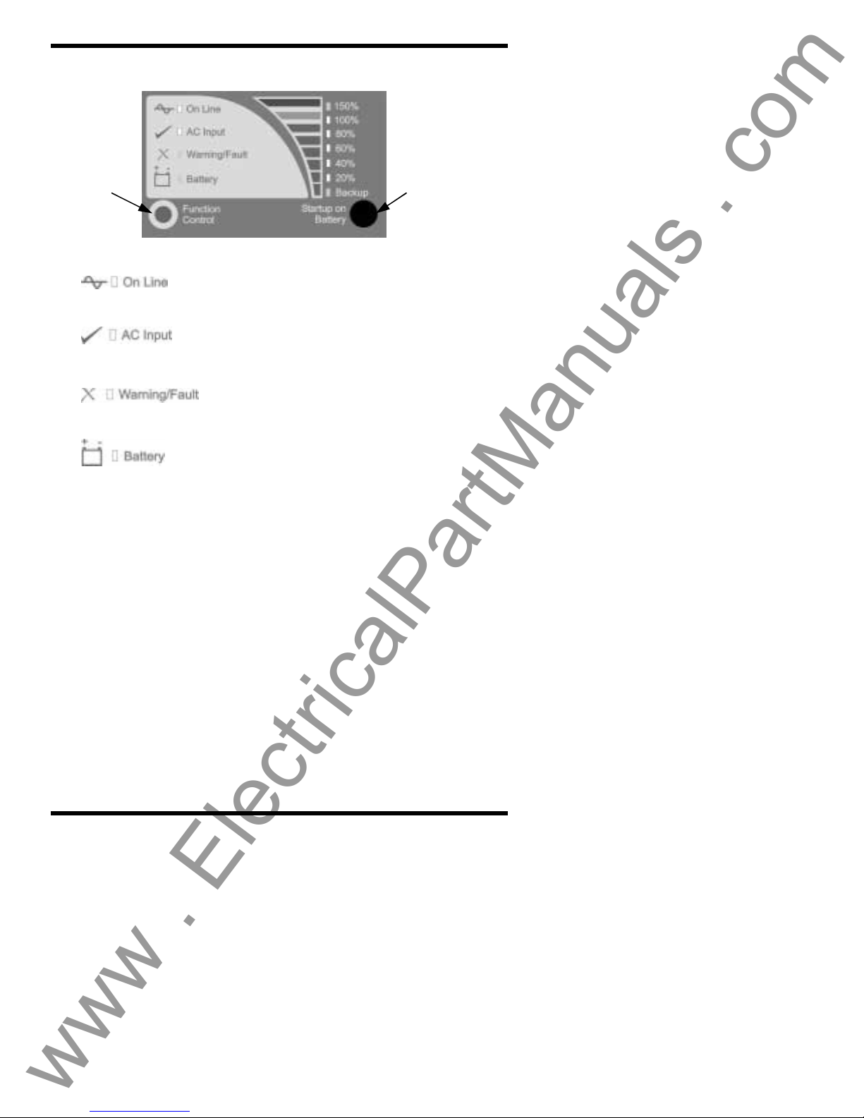
Display Panel Layout
TOSHIBA
Function
Control
Button
ON LINE (green lamp)
Lights green when the UPS’s inverter is
supplying power to the load.
AC INPUT (green lamp)
Lights green when normal AC input power
is being supplied to the UPS unit.
WARNING/FAULT (red lamp)
Lights red when the UPS unit is
experiencing an abnormal condition.
BATTERY (red lamp)
Lights red to indicate that a condition exists
that is affecting the batteries.
Starting the UPS System
Once the modules have been connected as shown in the preceding
section (UPS Connections, page 10) the UPS system is ready to be
started. There are two ways to start the system: from AC input
power (if present) or from batteries. If not already done, switch the
input breaker on (figure 1, page 9). If the “AC Input” LED is lit,
proceed on to “Starting when AC power is available”. If the LED is
not lit, there is no AC power available. If the unit is to be started
when AC power is not available proceed to “Starting on DC power.”
Starting When AC Power is Available
If the system is being started with AC input power the system is
started by switching the RUN/STOP switch to the RUN position
(RUN = 1, STOP = 0). When the RUN/STOP switch is in the RUN
position both the “AC Input” and the “On Line” LEDs should be lit.
When the unit is started with AC input power it is advisable to allow
time for the batteries to fully charge before any load is connected
(see “Battery Recharge Time”, page 16).
12
Startup on
Battery
Button

TOSHIBA
www . ElectricalPartManuals . com
Starting on DC Power
If no AC power source is available, the UPS can be started from
battery power. The length of UPS operation time on battery power
depends on the number of attached battery modules and the amount
of load the UPS is supporting. To start the UPS from battery power
follow these steps:
Step 1: Make sure the RUN/STOP switch is in the STOP position
(figure 1, page 9).
Step 2: Press the “Startup on Battery” button. The UPS will beep
indicating that AC power is not available and the Startup on Battery
mode has been activated.
Step 3: Switch the RUN/STOP switch to the RUN position. This
must be done within 5 seconds of the Startup on Battery mode
activation for the unit to startup using batteries.
Once the unit has started, the “On Line” LED will light, indicating that
the inverter is running and power is available at the output
receptacles. If the RUN/STOP switch is not switched to the RUN
position within those 5 seconds, the unit will return to shutdown
mode.
Stopping the UPS
There are two ways of turning the UPS off: switching from on line to
bypass mode, or completely shutting down.
Option 1
The first option is to place the UPS into bypass mode. Bypass mode
means that if there is AC power available, the UPS will route power
directly from the input source to the connected loads without any
conditioning. The UPS inverter is off during this state, but the
attached loads do not lose power during the transition. To place the
UPS into bypass mode, switch the RUN/STOP switch to the STOP
position. This mode is most often used manually during
maintenance and programming operations or automatically upon the
occurrence of an internal UPS fault. (For more information
concerning bypass mode see appendix E.)
Option 2
The other option is to turn the UPS off completely. This means that
in addition to the UPS’s inverter shutting down, all power will be
stopped to any equipment attached to the UPS. To shut the UPS
down completely switch the RUN/STOP switch to the STOP position.
Then switch the input breaker off (figure 1, page 9). Once the input
breaker has been switched off, all the LEDs should turn off. (If the
RUN/STOP switch is in the RUN position when the input breaker is
switched off, the unit will switch to battery backup mode. The unit
will continue to run for as long as the available battery reserves can
support the connected loads.)
13
 Loading...