

Toshiba 4200 series, U42B3F750C6CB, U42B3F10KC6CB Operation Manual

TOSHIBA
UNINTERRUPTIBLE POWER SYSTEM
THREE PHASE- 75/100kVA UPS
4200 SERIES
MANUFACTURED IN THE U.S.A.
Part Number: 51751-001
Date: March, 2003
OPERATION MANUAL

TOSHIBA
4200 SERIES
THREE PHASE- 75/100 kVA
UNINTERUPTIBLE POWER SYSTEM
OPERATION MANUAL
FOR MODELS
U42B3F750C6CB
U42B3F10KC6CB
TOSHIBA INTERNATIONAL CORPORATION
INDUSTRIAL DIVISION
13131 West Little York Rd., Houston, Texas 77041
1

TOSHIBA
NOTE
These Instructions are not intended to cover all of the details or variations
in equipment, nor to provide for every possible contingency to be met in
connection with installation, operation, or maintenance. This manual may
change without notice. Contact your local Toshiba sales office to verify
that this is the latest revision. Should further information be desired or
should particular problems arise which are not covered sufficiently for the
purchaser’s purposes, the matter should be referred to the local Toshiba
sales office.
The contents of this instruction manual shall not become a part of or
modify any prior or existing equipment, commitment, or relationship. The
sales contract contains the entire obligation of Toshiba International
Corporation’s UPS Division. The warranty contained in the contract
between the parties is the sole warranty of Toshiba International
Corporation’s UPS Division, and any statements contained herein do not
create new warranties or modify the existing warranty.
Any Electrical or mechanical modifications to this equipment, without prior
written consent of Toshiba International Corporation, will void all
warranties and may void UL/CUL listing. Unauthorized modifications also
can result in personal injury, death, or destruction of the equipment.
UNINTERUPTIBLE POWER SUPPLY
If additional information or technical assistance is required call Toshiba’s marketing department
toll free at 1-800-231-1412, or write to: Toshiba International Corporation, 13131 W. Little York
Rd., Houston, TX 77041-9990.
Please complete the following information for your records; however, please keep this manual
with the UPS equipment.
Model Number:
Serial Number:
Date of Installation:
Inspected By:
2
TOSHIBA
GENERAL SAFETY INSTRUCTIONS
Warnings in this manual appear in any of four ways:
1) Danger- The danger symbol is a lightning bolt mark enclosed in a triangle which precedes the
3/16” high letters spelling the word “DANGER”. The danger symbol is used to indicate imminently
hazardous situations, locations, and conditions which, if not avoided, WILL result in death,
serious injury, and/or severe property damage.
DANGER
2) Warning- The warning symbol is an exclamation mark enclosed in a triangle which precedes the
3/16” high letters spelling the word “WARNING”. The warning symbol is used to indicate
potentially hazardous situations and conditions which, if not avoided COULD result in serious
injury or death. Severe property damage COULD also occur.
WARNING
3) Caution- The caution symbol is an exclamation mark enclosed in a triangle which precedes the
3/16” high letters spelling the word “CAUTION”. The caution symbol is used to indicate potentially
hazardous situations and conditions which, if not avoided COULD result in injury. Equipment
damage may also occur.
CAUTION
4) Attention warnings- The attention warning symbol is an exclamation mark enclosed in a triangle
which precedes the 3/16” high letters spelling the word “ATTENTION”. The Attention warning
symbol is used to indicate situations and conditions that COULD cause operator injury and/or
equipment damage.
ATTENTION
Other warning symbols may appear along with the Danger and Caution symbol. The additional symbols are
used to specify special hazards. These warnings describe particular areas where special care and/or
procedures are required in order to prevent serious injury and possible death:
1) Electrical warnings- The electrical warning symbol is a lighting bolt mark enclosed in a triangle.
The Electrical warning symbol is used to indicate high voltage locations and conditions that
COULD cause serious injury or death if the proper precautions are not observed:
2) Explosion warnings- The explosion warning symbol is an explosion mark enclosed in a triangle.
The Explosion warning symbol is used to indicate locations and conditions where molten,
exploding parts that COULD cause serious injury or death if the proper precautions are not
observed:
3

TOSHIBA
TABLE OF CONTENTS
GENERAL SAFETY INSTRUCTIONS................................................................................. 3
TABLE OF CONTENTS....................................................................................................... 4
IMPORTANT SAFETY INSTRUCTIONS ............................................................................. 6
1.0 Product Description.................................................................................................. 8
1.1 Theory of Operation.............................................................................................................................. 8
1.2 Application and use .............................................................................................................................. 8
1.3 Power Backup....................................................................................................................................... 8
1.4 Power Conditioning .............................................................................................................................. 8
2.0 Uncrating/Inspection/Storage/Disposal................................................................... 9
2.1 Uncrating the new UPS equipment: ..................................................................................................... 9
2.2 Inspection of the new UPS equipment ............................................................................................... 10
2.3 Storage of UPS equipment................................................................................................................. 10
2.4 Disposal .............................................................................................................................................. 10
3.0 Precautions...............................................................................................................11
3.1 Installation Precautions ...................................................................................................................... 11
3.2 Pre-start Precautions.......................................................................................................................... 12
3.3 Operating Precautions........................................................................................................................ 12
4.0 UPS Connections .................................................................................................... 13
4.1 Power Connections 75 and 100kVA................................................................................................... 13
4.1.1 Recommended Wire Size and Tightening Torque For UPS Input and Output Terminals ............ 14
4.1.2 Power Connection Cable Routing ................................................................................................. 15
4.2 Control Circuit and External Battery Interface Connections 75 and 100kVA ..................................... 16
4.2.1 Recommended Wire Size and Tightening Torque UPS Control and Battery Interface................. 16
4.3 Communication Interface.................................................................................................................... 17
4.3.1 Remote Contact (IBM AS/400)...................................................................................................... 17
4.3.2 RS-232C ........................................................................................................................................ 18
4.3.3 UPS Shutdown (via RS-232C) ...................................................................................................... 18
5.0 Specifications.......................................................................................................... 19
5.1 4200 Series Specifications 75 and 100kVA @ Standard 208Vac Output.......................................... 19
6.0 Operating the UPS................................................................................................... 20
6.1 Operating the UPS ............................................................................................................................. 20
6.1.1 AC Input Mode (normal operation) ................................................................................................ 20
6.1.2 Circuit-bypass Mode...................................................................................................................... 20
6.1.3 Battery Backup Mode .................................................................................................................... 21
6.2 Battery Backup Time and Discharge Process....................................................................................21
6.3 Battery Low Voltage Tolerances......................................................................................................... 22
6.4 Battery Recharging............................................................................................................................. 22
6.5 Front Panel Layout (All Units)............................................................................................................. 23
6.6 EPO (Emergency Power Off) Function .............................................................................................. 24
6.7 Audible Alarm Functions..................................................................................................................... 24
6.8 Light Emitting Diode (LED) Functions ................................................................................................ 25
6.8.1 Light Emitting Diode (LED) System Status.................................................................................... 25
6.9 Liquid Crystal Display (LCD) Functions.............................................................................................. 26
6.9.1 Line-1 System Messages .............................................................................................................. 26
6.9.2 Line-2 System Fault Messages ..................................................................................................... 26
6.9.3 Line-3 System Messages .............................................................................................................. 26
6.9.4 Line-4 System Messages .............................................................................................................. 27
6.10 Initial Battery Charge .......................................................................................................................... 28
6.11 Start-up Procedure ............................................................................................................................. 29
6.12 Shutdown Procedure .......................................................................................................................... 30
6.13 Keypad Overview................................................................................................................................ 31
6.14 Key Functions ..................................................................................................................................... 32
6.14.1 MONI ............................................................................................................................................. 32
6.14.2 IN ................................................................................................................................................... 32
4

TOSHIBA
6.14.3 OUT ............................................................................................................................................... 32
6.14.4 BATT Key ...................................................................................................................................... 33
6.14.5 MENU, F1, ENTER, UP, & DOWN Keys....................................................................................... 33
6.14.6 BATT TEST Key ............................................................................................................................ 33
6.14.7 BUZZ STOP Key ........................................................................................................................... 34
6.14.8 RESET Key.................................................................................................................................... 34
6.15 Menu Data Screens............................................................................................................................ 35
6.15.1 Settings for Calendar and Clock.................................................................................................... 35
6.15.2 Adjusting Buzzer Volume .............................................................................................................. 35
6.15.3 Settings for Display Duration ......................................................................................................... 35
6.15.4 Run Switch Select ......................................................................................................................... 36
6.15.5 Serial Com Station Address .......................................................................................................... 36
6.15.6 Output Voltage Adjustment............................................................................................................ 37
6.15.7 Charge Mode Select...................................................................................................................... 37
6.15.8 Reset to Default Settings............................................................................................................... 38
6.16 Overload Operation ....................................................................................................................... 38-39
7.0 UPS Protection System .......................................................................................... 40
7.1 System Protection Features ............................................................................................................... 40
7.2 System Protection Functions.............................................................................................................. 40
8.0 Preventive and Scheduled Maintenance / Part Replacement.............................. 41
8.1 Preventive Maintenance ..................................................................................................................... 41
8.2 Parts Replacement ............................................................................................................................. 41
9.0 External Layouts / Dimensions / Shipping Weights ............................................. 42
9.1 External Dimensions 75 and 100kVA................................................................................................. 42
9.2 Shipping Dimensions 75, and 100kVA .............................................................................................. 43
5
TOSHIBA
p
IMPORTANT SAFETY INSTRUCTIONS
SAVE THESE INSTRUCTIONS
And 100kVA that should be followed during the installation, operation, and maintenance of the UPS
Systems. Refer to the Battery System Manual for details on operating and maintaining the battery units
for each system.
UPS System’s output is not equipped with an over-current protection device, nor an output disconnect for the
AC output; therefore, a circuit breaker should be provided, by the user, between the UPS output and the
critical load input. This device should be rated as follows:
Model Rated Output Device Rating
75kVA 208/120Vac 240V, 270A
Model Rated Output Device Rating
100kVA 208/120Vac 240V, 350A
The maximum ambient temperatures in which the Uninterruptible Power Systems should be operated in is
40°C. (25°C max. if battery cabinet is subject to same ambient)
The nominal battery voltage for 75kVA is 240VDC; 100kVA is 324VDC
This manual contains important
instructions for 4200 Series 75/
A qualified Toshiba Representative who is knowledgeable of batteries and the required precautions should
only perform servicing of the batteries. Keep unauthorized personnel away from batteries.
Refer to the Battery System Manual, when scheduling maintenance or battery replacement.
CAUTION
either indirect or consequential damage or injury that may result from the use of this equipment.
Misuse of this equipment could result in human injury and equipment
damage. In no event will Toshiba Corporation be responsible or liable for
Do not dispose of the batteries in a fire. The batteries may explode.
CAUTION
CAUTION
WARNING
and/or flame. An authorized, trained technician must perform annual preventative maintenance.
WARNING
resulting in secondary faults such as odor, smoke, and fire.
Do not open or mutilate the batteries. Released electrolyte is harmful to
the eyes and skin and could also be toxic.
This unit contains sealed lead acid batteries. Lack of preventative
maintenance could result in batteries exploding and emitting gasses
Failure to replace a battery before it becomes exhausted may cause the
case to crack,
ossibly releasing electrolytes from inside the battery, and
6
TOSHIBA
WARNING
WARNING
your UPS system. Refer to service manual.
DANGER
1) Verify that the UPS is off and is disconnected from the power source.
2) Remove watches, rings or other metal objects.
3) Use tools with insulated handles to prevent inadvertent shorts.
4) Wear rubber gloves and boots.
5) Do not lay tools or metal parts on top of batteries.
6) Determine if the battery is inadvertently grounded. If inadvertently grounded, remove
source of ground.
electrical shock.
removed during installation and maintenance.
7) Verify circuit polarities prior to making connections.
8) Disconnect charging source and load prior to connecting or disconnecting terminals.
9) VRLA batteries contain an explosive mixture of hydrogen gas. Do not smoke, or create a flame
or spark in the immediate area of the batteries. This includes static electricity from the body.
10) Do not attempt to open the batteries in order to add water or sample the specific gravity of the
electrolyte. The batteries are valve regulated lead acid type and such servicing is not possible
without damaging the battery.
11) Use proper lifting means when moving batteries and wear all appropriate safety clothing and
equipment.
12) Do not dispose of lead acid batteries except through channels in accordance with local, state
and federal regulations.
Personnel knowledgeable of batteries and the required precautions
should perform installation and servicing of batteries. Keep
Unauthorized personnel away from the batteries.
Proper maintenance to the battery system of this unit must be done by a
qualified service technician, this is essential to the safety and reliability of
A battery can present a risk of electrical shock and high short
circuit current.
when working with batteries.
Contact with any part of a grounded battery can result in
The likelihood of such shock will be reduced if such grounds are
The following precautions should be observed
INSTRUCTIONS IMPORTANTES CONCERNANT
CONSERVER CES INSTRUCTIONS
ATTENTION
ATTENTION
ATTENTION
LA SÉCURITÉ
Cette notice contient des
instructions importantes
concernant la sécurté
Un battery puet présenter un risque de choc électrique, de brûlure
par transfert d’ énergie.
Por le replacement, utiliser le même nombre de batteries du modéle
suivant.
L’élimination des batteries est règlementèe. Consultar les codes
locaux à cet effet.
7

1.0 Product Description
1.1 Theory of Operation
An Uninterruptible Power Supply (UPS) is a system that is installed between the commercial
power and the load equipment. The UPS provides steady AC output power during
commercial power fluctuations and interruptions.
During normal operation the UPS utilizes commercial AC power and removes high voltage
spikes and transients caused by switching and faults on the main utility. The result of this
process is maximum power conditioning and regulation.
If the AC power supplied to the UPS drops below a specified voltage level, the unit's batteries
automatically begin supplying power instead of receiving it. This insures that the loads
connected to the UPS continue to receive power with no interruption. This power is provided
for a long enough time so that the load can be shut down in an orderly fashion. This prevents
loss of data and possible damage to both hardware and software.
When AC input power becomes available again, operation returns to normal. The UPS
batteries begin to recharge, so they will be ready for the next power interruption.
1.2 Application and use
Toshiba's 4200 Series of on-line, Uninterruptible power systems (UPS) provide continuous
computer grade AC power in a compact, efficient, high performance unit. The UPS assures
safe, reliable operation of critical office equipment, ranging from personal computers to minicomputers to local area networks (LAN). All units feature an audible alarm that sounds if the
battery voltage drops below standard during use. This is an additional aid to help in retaining
the valuable office data banks, and all units allow for computer interfacing.
TOSHIBA
1.3 Power Backup
During an electrical power failure the UPS unit's batteries automatically supply DC power to the
inverter that supports the load equipment, without interruption. For example, when used to
support a computer, the UPS’s back-up assures additional time to complete your activity and
store data after a power failure occurs.
1.4 Power Conditioning
While commercial power is present, the UPS supplies conditioned power to the load while
maintaining its batteries in a charged condition. The UPS protects the connected load against
the normal, everyday problems associated with heavy use of raw commercial power, including
power sags, surges, signal interference, and spikes. This protection keeps power-line problems
from reaching your load, where it can cause equipment to operate erratically, or damage
software and hardware.
8
TOSHIBA
2.0 Uncrating/Inspection/Storage/Disposal
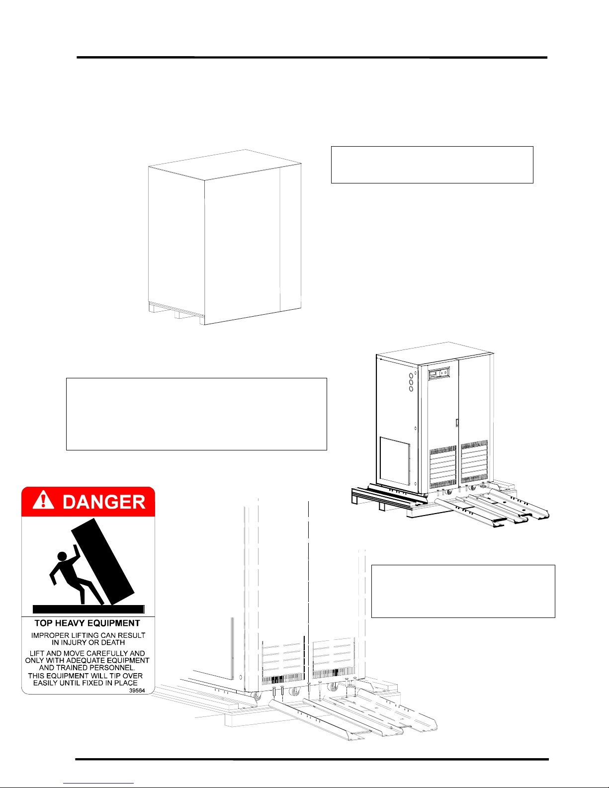
2.1 Uncrating the new UPS equipment:
Upon receipt of the UPS, a careful inspection for shipping damage should be made.
1) Remove the screws that attach the
shipping crate to the pallet; remove the
crate and foam packing material.
2) Unbolt the rails from both the unit and the shipping
pallet. Place the rails on the front of the pallet as
shown in figure 2.2 and figure 2.3. Use the four
1/2x3" bolts used to secure the rails to the shipping
pallet to attach the rails as shown to the front of the
pallet.
3) Place the tie brackets as shown in
figure 2.3 in the slots at the lower
end of the ramps. SLOWLY roll the
unit down the ramp.
9

TOSHIBA
2.2 Inspection of the new UPS equipment
After Uncrating:
1) Check the unit for loose, broken, bent or other damaged parts. If damage has occurred
during shipment, keep all original crating and packing materials for return to the shipping
agent. The equipment warranty will not apply to units that are damaged during shipment.
2) Check to see that the rated capacity and the model number specified on the nameplate
conform to the order specifications.
2.3 Storage of UPS equipment
If the UPS equipment is to be subject to long or short-term storage, the following guidelines
should be used.
Avoid:
1) Storage in sites subject to extreme changes in temperature or high humidity.
2) Storage in sites subject to exposure of high levels of dust or metal particles.
3) Storage on inclined floor surfaces or in sites subject to excessive vibration.
Before storing:
1) Charge the system's batteries.
2) Perform a complete system shutdown as described in section 6.12 of this
manual.
Storing:
1) Store within a temperature range of -20° to 40° C (-4° to 104° F).
2) For best results, store the UPS in the original shipping container and place on a
wood or metal pallet.
3) The optimum storage temperature is 21° C (70° F). Higher ambient temperatures
cause UPS batteries to need recharging more frequently.
4) If stored in an ambient temperature under 20° C (68° F); recharge the batteries
every 9 months.
5) If stored in an ambient temperature of 20° to 30° C (68° to 86° F); recharge the
batteries every 6 months.
6) If stored in an ambient temperature of 30° to 40° C (86° to 104° F); recharge the
batteries every 3 months.
2.4 Disposal
Please contact your state environmental agency for details on proper disposal of electrical
components and packaging in your particular area.
ATTENTION
It is illegal to dump lead-acid batteries in landfills or dispose of
improperly. Please help our Earth by contacting the environmental
protection agencies in your area, the battery manufacturer, or call Toshiba
toll-free at (800) 231-1412 for more information about recycling batteries.
10
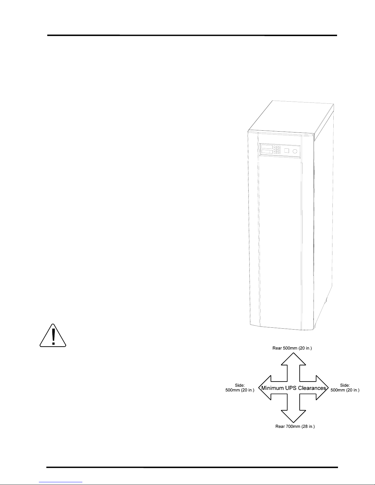
3.0 Precautions
Based on the 4200 Series UPS unit's external dimensions and the way the outer panels are
removed; minimum amounts of unobstructed space around the unit is necessary for ventilation
and maintenance access. Figure 3.1 shows the minimum clearances required for proper UPS
site installation.
3.1 Installation Precautions
1) Do not install the UPS on an inclined surface,
2) Do not allow liquids or foreign objects to get
3) Allow at least 700 mm (28 in) on the front side
4) Do not install the UPS in a location that is
TOSHIBA
or areas that are subject to frequent vibrations
or jolting. This could damage UPS circuits.
inside the UPS.
and 500 mm (20 in) on the rear and sides of
the UPS unit for air ventilation and
maintenance access.
subject to high humidity. Also, do not install
the unit in areas that are exposed to direct
sunlight, or contaminated areas subject to
high levels of airborne dust, metal particles, or
flammable gasses.
5) Verify the ventilation and air conditioning
system at the site is capable of removing the
heat generated by the UPS unit (see Section,
5.1 Specifications, "Environment").
Ambient temperature range for operating the UPS
is 0° to 40°C (32° ~ 104°F); 25°C (77°F) is the
recommended operating temperature for
maximum battery life.
6) Avoid installation near sources of electrical
noise. Always make sure that the unit's
ground is intact to prevent electrical shock
and help prevent electrical noise.
7) This UPS generates and radiates radiofrequency energy during operation. Although
RFI noise filters are installed inside the unit
there is no guarantee that the UPS will not
influence some sensitive devices which are
operating in near proximity. If such
interference occurs, the UPS should either be
installed farther away from the affected
equipment and/or powered from a different
source than the affected equipment.
Figure 3.1
11

TOSHIBA
3.2 Pre-start Precautions
Before connecting the UPS to a power source; move the MCCB switch (ON/OFF), on the side
panel, to the OFF position and move the operation STOP/RUN key switch, on the front panel
(See Section 9 for location), to the STOP position.
3.3 Operating Precautions
1) The UPS should not be powered up until the entire operation manual has been reviewed,
and understood.
2) The input power source voltage must be within +10% to -15% of the rated input voltage.
The input frequency must be within the rated input frequency range. Voltages and
frequencies outside of the permissible range may cause internal protection devices to
activate.
3) The UPS should not be used with a load whose rated input is greater than the rated UPS
output.
4) Do not use the UPS to provide power to motors that require high starting current or a long
starting time such as vacuum cleaners and machine tools.
5) Do not insert metal objects or combustible materials in the unit's ventilation slots.
6) Do not place, hang, or paste any objects on the top or on the exterior surfaces of the UPS.
12
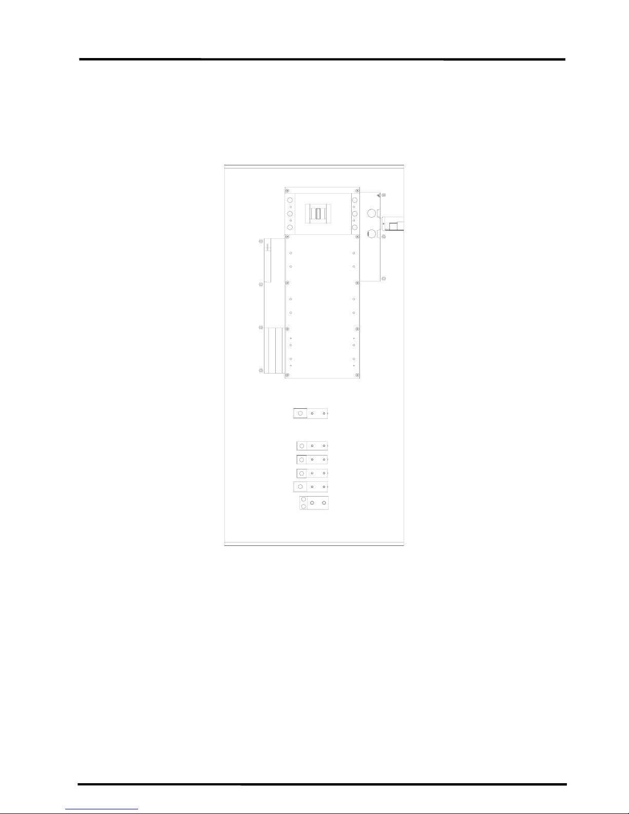
4.0 UPS Connections
4.1 Power Connections 75 and 100kVA
The following illustrates the wiring connections to the Input and Output Terminations points for
the 75 and 100kVA UPS Models
4.1.1
TOSHIBA
H1
H2
H3
Input (N)
L1
L2
L3
(N)
GND
13
 Loading...