

Toshiba TDP-TW300U, TDP-TW300E, TDP-TW300B, TDP-TW300C, TDP-T250U Service Manual
...
FILE NO. 330-200510
REVISED. 1
SERVICE MANUAL
Document Created in Japan Jun., 2005
TDP- TW300U
TDP- TW300E
TDP- TW300B
TDP- TW300C

II
Table of Contents
Chapter 1 .......................................................................................... 1-1
Specifications.....................................................................................1-1
Using the Menus................................................................................1-4
Parts on the Rear Panel.....................................................................1-5
List of Supported Signals................................................................... 1-6
Chapter 2 .......................................................................................... 2-1
Replaceable Part Hierarchy ...............................................................2-1
Required Tools ................................................................................... 2-2
Parts Replacement ............................................................................2-3
Chapter 3 .......................................................................................... 3-1
SINGOWS 2000.................................................................................3-1
Chapter 4 .......................................................................................... 4-1
Firmware Upgrade .............................................................................4-1
Chapter 5 .......................................................................................... 5-1
Wiring Diagram ..................................................................................5-1
Block Diagram....................................................................................5-2
Chapter 6 .......................................................................................... 6-1
LED Display ....................................................................................... 6-1
Troubleshooting..................................................................................6-3
Operation of Power Supply (APS-M550)..........................................6-25
Chapter 7 .......................................................................................... 7-1
Electrical Adjustment ......................................................................... 7-1
Lighting Position Adjustment............................................................ 7-16
Chapter 8 .......................................................................................... 8-1
Functional Test ...................................................................................8-1
Chapter 9 .......................................................................................... 9-1
RS-232C Control by Hyperterminal ...................................................9-1
Chapter 10 ........................................................................................ 10-1
Spare Parts List ...............................................................................10-1
Contents
1-1
Chapter 1
Specifications
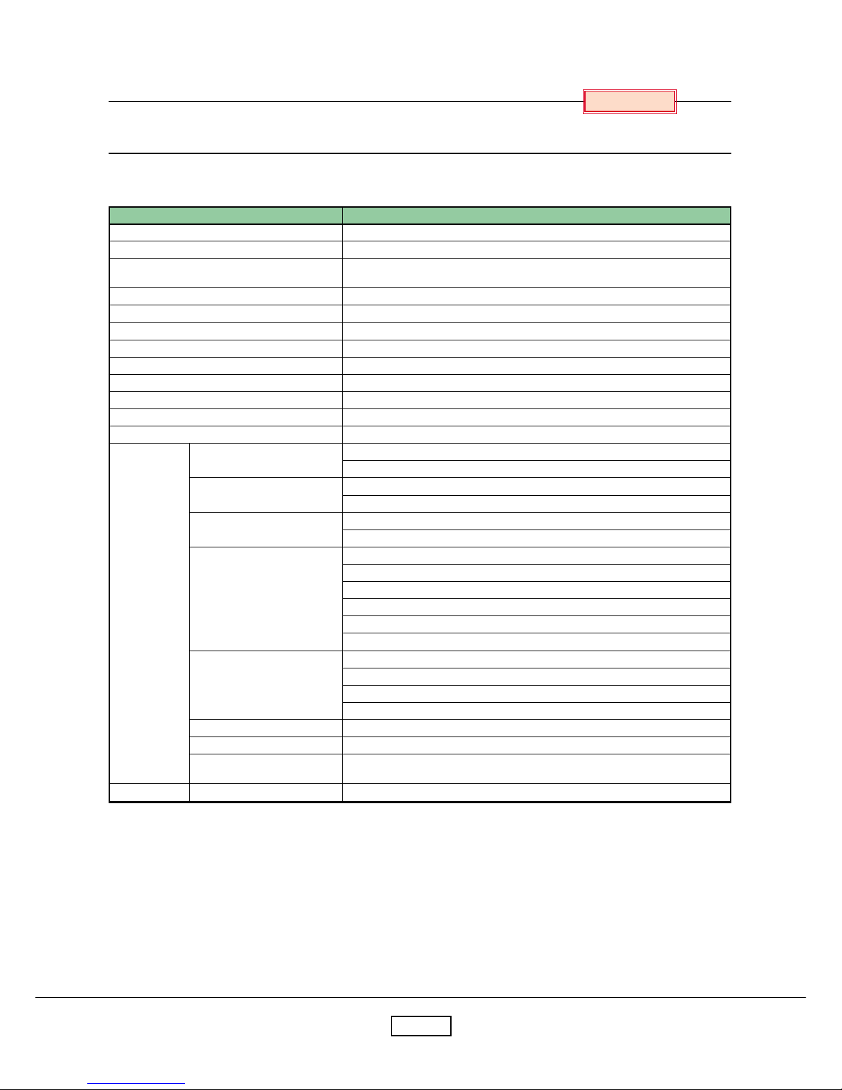
n List of general specifications
Item
Consumption power
Weight
External dimensions
(including protruding parts)
Cabinet material
Conditions for usage environment
Display pixels
Picture elements
Lens
Lamp
Projection screen size
Projection distance
Speaker
CONTROL terminal
COMPUTER (Y/PB/PR) 1
IN terminal
COMPUTER (Y/PB/PR) 2
IN terminal
COMPUTER (Y/PB/PR) 3
IN terminal
Connection
terminal
VIDEO IN terminal
MONITOR OUT terminal
AUDIO OUT terminal
USB port
PC card slot
Specification
400 W
5.5 kg
340 × 115 × 328 mm (W × H × D)
PC + ABS resin and ABS resin
Temp. : 5°C to 35°C ; relative humidity : 30% to 70%
1 chip DMD™
786,432 pixels (1024H × 768 V)
Zoom lens F = 2.4-3.0, f = 21-31.5 mm (electric powered)
High-pressure mercury lamp (300 W)
33-300 inches
1.17-13.76 m
4 W + 4 W (stereo)
LAN : 10BASE-T / 100BASE-TX
RS-232C : Mini DIN 8 pin
D VI-I : Analog RGB / Digital RGB / Y/PB/PR (dual use)
AUDIO : 3.5 mm dia. stereo mini-jack, 1.5 V (rms)
Mini D sub 15 pin Analog RGB / Y/PB/PR (dual use)
AUDIO : 3.5 mm dia. stereo mini-jack, 1.5 V (rms), 22 kΩ or more
G/Y: BNC Jack G: 0.7 V (p-p), 75Ω Y: 1 V (p-p), 75Ω
B/PB : BNC J ack 0.7 V (p-p), 75Ω
R/PR : BNC J ack 0.7 V (p-p), 75Ω
HD (Horizontal sync signal) : BNC Jack TTL level (Pos/neg polarity)
VD (Vertical sync signal) : BNC J a ck TTL lev el (Pos/neg polarity)
AUDIO : 3.5 mm dia. stereo mini-jack, 1.5 V (rms), 22 kΩ or more
S-VIDEO : Mini DIN 4 pin
AUDIO (L/R) : RCA Pin J ac k × 2, 1.5 V (rms), 22 kΩ or more
VIDEO : RCA Pin Jack, 1 V (p-p), 75Ω
AUDIO (L/R) : RCA Pin J ac k × 2, 1.5 V (rms), 22 kΩ or more
Mini D sub 15 pin RGB / Y/PB/PR (dual use)
3.5 mm dia. stereo mini-jack, 1.5 V (rms), 22 kΩ or more
USB 2.0 High-speed enabled Type A;
Output voltage: +5 V DC; Supply current: 500 mA
Compliant with PC Card Standard TYPE 11
Notes
• This model complies with the above specifications.
• Designs and specifications are subject to change without notice.
• This model may not be compatible with features and/or specifications that may be added in the future.
n Separately sold product
Replacement lamp model : TLPLW6
Chapter 1
1-2
Chapter 1
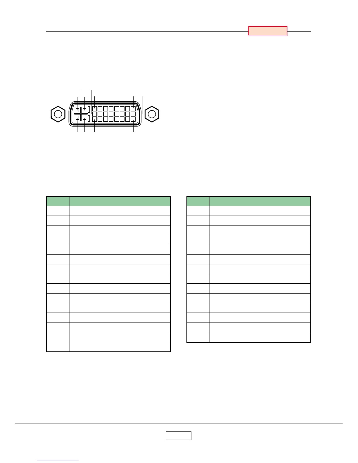
n Pin assignment of DVI-I terminal
COMPUTER IN 1
Analog input signal
• Analog RGB input
RGB signals : 0.7 V (p-p) 75 Ω
Horizontal sync signal : TTL level (Pos/neg polarity)
Vertical sync signal : TTL level (Pos/neg polarity)
• Y/PB/PR input
Y signal : 1.0 V (p-p) 75 Ω
PB/PR signals : 0.7 V (p-p) 75 Ω
D VI digital & analog connector
Pin No.
1
2
3
4
5
6
7
8
9
10
11
12
13
14
15
Pin description
T.M.D.S. data 2 –
T.M.D.S. data 2 +
T.M.D.S. data 2/4 shielded
T.M.D.S. data 4 – (N.C)
T.M.D.S. data 4 + (N.C)
DDC clock
DDC data
Analog vertical sync signal
T.M.D.S. data 1 –
T.M.D.S. data 1 +
T.M.D.S. data 1/3 shielded
T.M.D.S. data 3 – (N.C)
T.M.D.S. data 3 + (N.C)
+5 V power source
GND (+5 V, H Sync & V Sync )
Pin No.
16
17
18
19
20
21
22
23
24
C1
C2
C3
C4
C5
Pin description
Hot plug detection
T.M.D.S. data 0 –
T.M.D.S. data 0 +
T.M.D.S. data 0/5 shielded
T.M.D.S. data 5 – (N.C)
T.M.D.S. data 5 + (N.C)
T.M.D.S. clock shielded
T.M.D.S. clock +
T.M.D.S. clock –
Analog video signal (R / PR)
Analog video signal (G / Y)
Analog video signal (B / PB)
Analog horizontal sync signal
Analog GND (R/PR, G/Y, B/PB)
C5
C3 24C4
C1C2
8
1
16
17 9
1-3
Chapter 1
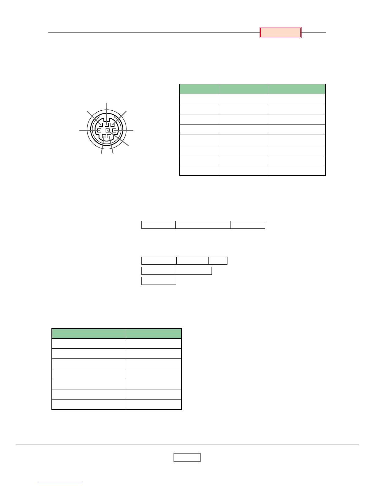
n CONTROL terminal
• Pin assignment
Pin No.
1
2
3
4
5
6
7
8
Mini DIN 8 pin connector
Signal Name
RXD
CTS
DSR
GND
RTS
N.C
TXD
GND
Description
Receiving data
Consent to send
Data set ready
Signal ground
Request to send
No connection
Sending data
Signal ground
• Interface format
1. Communication method RS-232C, 9600 bps, No Parity, Data Length: 8 bits;
Stop Bit Length: 1 bit
2. Communication format STX (02 h) Command (3 Byte) ETX (03 h)
Only 1 command valid per communication.
3. Data format For input commands, only ASCII-compliant all-uppercase alphanumeric
characters supported.
4. Replies Acknowledge ACK (06 h) CR (0 Dh) Data : Normally ended
ACK (06 h) ESC (1 Bh) : Aborted
No acknowledge NAK (15 h)
If commands are to be sent consecutively, wait for the response from the projector before sending the next
command.
• Main Commands
7
68
5
4
3
2
1
Item
Power on
Power off
Icon display on
Icon display off
Auto setting (RGB input)
Status display on
Status display off
Command
PON
POF
MO0
MO1
PAT
DON
DOF
Note
• Contact your dealer for control cable and other commands.
1-4
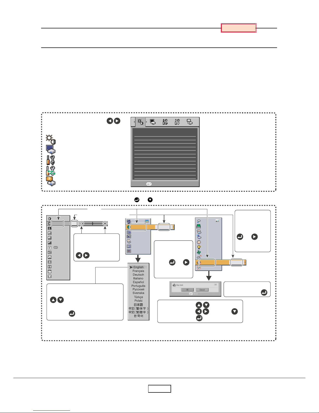
Using the Menus
You can call up on-screen menus, and conduct a number of adjustments and settings using the operation
buttons on the control panel (main unit side) and remote controller.
n How to use the menus
The menu shown below is for operation instructions purposes and might differ from the actual display.
1. Press the MENU button Display the Setting display menu.
2. Select a Category
Execute
+16
+16
+16
+16
+16
+64
+64
+32
255
255
30
Standard
Brightness +12
Image adjustment
Contrast
Brightness
Picture mode
R-level
G-level
B-level
Auto setting
Phase
Frequency
H-position
V-position
Clamp 1
Clamp 2
+12
+12
Bright
+12
+12
+12
+12
+12
+12
+12
+12
+12
To image adjustment menu
On
On
On
Language English
Standard
Off
Off
On
Manual
Low
1
Ye s
Key lo ck Off
Toggle items with .
Select items with and press .
Fix selection with .
Select a category by using .
There are following five categories:
Displays the current
adjustments and settings
of selected category.
Item shown with gray
cannot be adjusted with
the current input source.
Image adjustment menu
Display setting menu
Default setting menu
Control setting menu
Status display menu
The figure shows displays given for operation instructions purposes.
As the display may differ depending on the item, use the following pages as a reference.
Item
Adjustment/Setting Value
These marks signify
the items can be
adjusted/set by using
.
These marks signify the items can
be selected from the list by using
.
After an item is selected, apply it by
pressing .
These marks
signify that there
are options.
Press or
to display a list of
options.
These marks
signify that
there are setting
screens. Press
or to
display a list of
setting screens
* When no item is
changed, press .
3. Adjustments & Settings Press
or
to open the menu.
4. Back RETURN button
5. Press the MENU button The Setting display (2) is displayed.
6. End Press the MENU button or RETURN button.
(The menu disappears 30 seconds after the last operation.)
Chapter 1
1-5
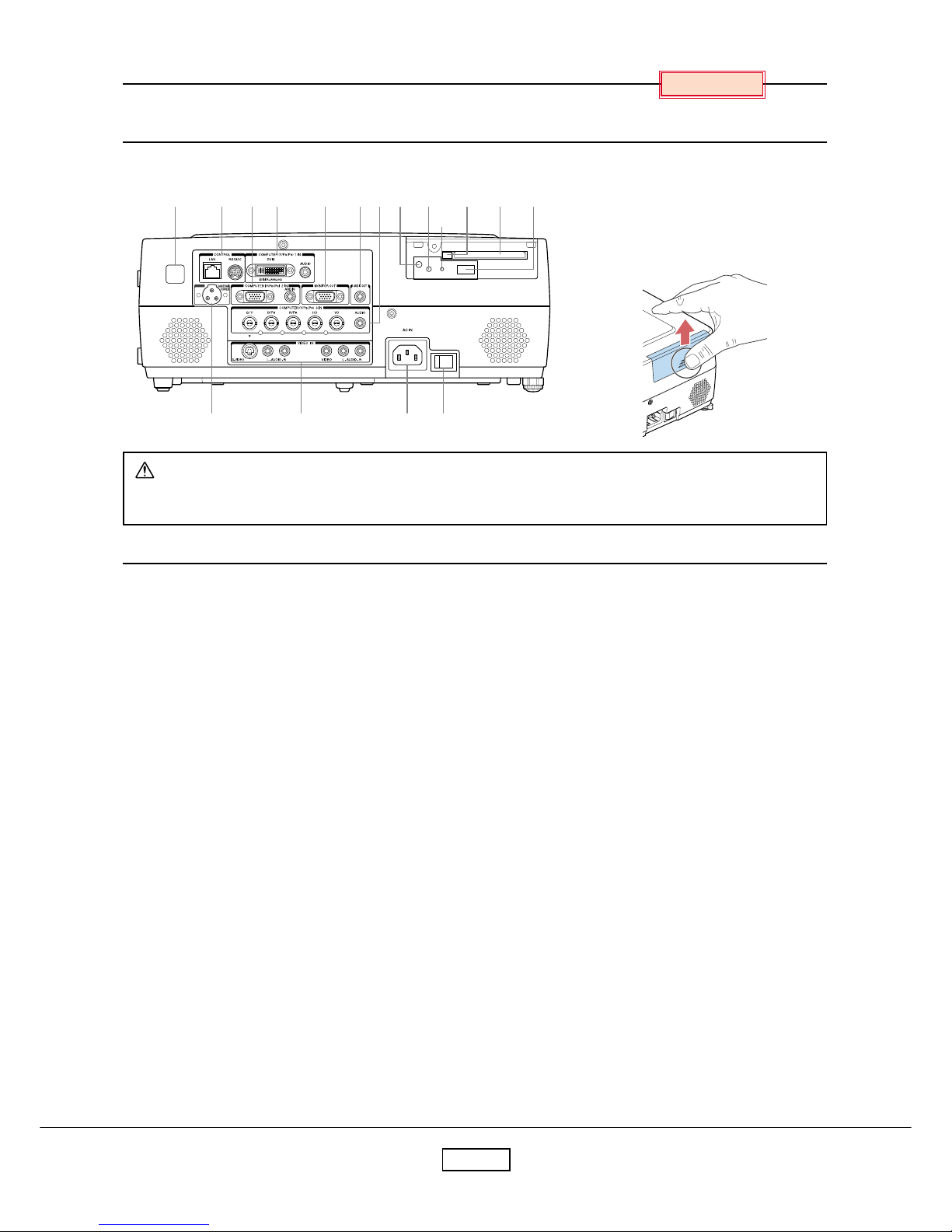
P arts on the Rear Panel
Name : Main Function
(1) Infrared remote sensor : Senses commands from the remote controller.
(2) CONTROL terminal
LAN : Connects a network cable.
RS232C : When operating the projector via a computer, connect this to the controlling
computer’s RS-232C port.
(3) COMPUTER (Y/P
B/PR) 2 IN terminal
RGB : Input analog RGB signal from a computer or other source, or a component
video signal (Y/P
B/PR) from video equipment.
AUDIO : Input audio signals.
(4) COMPUTER (Y/P
B/PR) 1 IN terminal
DVI-I : Input analog or digital RGB signal from a computer, or a component video
signal (Y/P
B/PR) from video equipment.
AUDIO : Input audio signals.
(5) MONITOR terminal : Connect to a computer display, etc.
(6) AUDIO OUT terminal : Outputs audio signals.
(7) COMPUTER (Y/P
B/PR) 3 IN terminal
BNC : Input G/B/R/HD/VD signal from a computer, or a component video signal
(Y/P
B/PR) from video equipment.
AUDIO : Input audio signals.
(8) CARD indicator : Displays PC card’s status.
(9) UNMOUNT button : Press before removing PC card.
(10) RESET switch (inside depression) : Press if CARD indicator turns red.
(11) Eject button : Press to remove PC card.
(12) PC card slot : Insert PC cards here.
(13) USB terminal : Connects a commercial USB memory.
(14) CAMERA POWER terminal : DC power supply terminal (+15 V). Reser ved for future use.
(15) VIDEO IN terminal
S-VIDEO : Input S video signals from video equipment.
AUDIO (L/R) : Input audio signals from video equipment.
VIDEO : Input video signals from video equipment.
AUDIO (L/R) : Input audio signals from video equipment.
(16) AC IN socket : Connect the supplied power cord here.
(17) Main power switch : AC power line ON (standby)/OFF.
Chapter 1
n Removing the slot cover
Press on the circle (“O”) while
sliding the cover in the direction of
the arrow. The cover will come off.
CA UTION
Do not carry the projector by having the slot cover part.
Doing so may cause that cover to come off, resulting in the projector malfunction, injury or damage.
(1)
(14) (15) (
16)(17
)
(2) (3)(4) (5)
(6) (8) (9)
(10)
(11) (13)(12)(7)
1-6
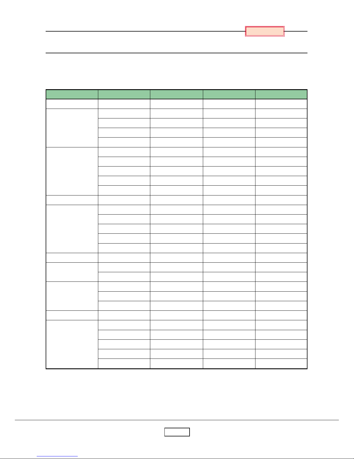
List of Supported Signals
n List of supported signals (RGB signals)
This projector supports the following RGB signals. Note, however, that depending on the computer model,
the screen may show flicker or streaking. Please adjust the projector if this happens.
Resolution
720 × 400
640 × 480
800 × 600
832 × 624
1024 × 768
1152 × 864
1280 × 960
1280 × 1024
∗1400 × 1050
∗1600 × 1200
Mode
720x400_85
VGA_60
VGA_72
VGA_75
VGA_85
SVGA_56
SVGA_60
SVGA_72
SVGA_75
SVGA_85
MAC16"
XGA_60
XGA_70
XGA_75
XGA_85
MAC19"
SXGA1_75
QuadVGA_60
QuadVGA_85
SXGA3_60
SXGA3_75
SXGA3_85
SXGA+
UXGA_60
UXGA_65
UXGA_70
UXGA_75
UXGA_85
Refresh rate (Hz)
85.039
59.940
72.809
75.000
85.008
56.250
60.317
72.188
75.000
85.061
74.550
60.004
70.069
75.029
84.997
74.700
75.000
60.000
85.002
60.020
75.025
85.024
59.978
60.000
65.000
70.000
75.000
85.000
H-frequency (kHz)
37.927
31.469
37.861
37.500
43.269
35.156
37.879
48.077
46.875
53.674
49.725
48.363
56.476
60.023
68.667
60.134
67.500
60.000
85.938
63.981
79.976
91.146
65.317
75.000
81.250
87.500
93.750
106.250
Clock (MHz)
35.500
25.175
31.500
31.500
36.000
36.000
40.000
50.000
49.500
56.250
57.283
65.000
75.000
78.750
94.500
79.857
108.000
108.000
148.500
108.000
135.000
157.500
121.750
162.000
175.500
189.000
202.500
229.500
∗ Depending on the model of computer, the image may not be displayed properly with the DVI input.
Note
• Signals which resolution exceeds the native resolution (1024 × 768 pixels) will be compressed.
For this reason, some information may be lost, or image quality may be affected.
Chapter 1

1-7
Chapter 1
n List of supported signals (Y/PB /PR signals)
Mini D sub 15 Pin connector
Input Signal
• RGB input
RGB signals : 0.7 V (p-p) 75 Ω
Horizontal sync signal : TTL level (Pos/neg polarity)
Vertical sync signal : TTL level (Pos/neg polarity)
• Y/P
B/PR input
Y signal : 1.0 V (p-p) 75 Ω
P
B/PR signals : 0.7 V (p-p) 75 Ω
Pin
No.
1
2
3
4
5
6
7
8
9
10
11
12
13
14
15
Signal format
∗ 480i (525i)@60Hz
480p (525p)@60Hz
∗ 576i (625i)@50Hz
576p (625p)@50Hz
720p (750p)@60Hz
720p (750p)@50Hz
1080i (1125i)@60Hz
1080i (1125i)@50Hz
∗ DVI digital input is not supported.
n List of supported signals (Video, S-Video signals)
n Pin assignment of COMPUTER-2 & MONITOR terminals
∗ Do not connect anything.
fh (kHz) fv (Hz)
15.73 59.94
31.47 59.94
15.63 50.00
31.25 50.00
45.00 60.00
37.50 50.00
33.75 60.00
28.13 50.00
Video mode
NTSC
PAL
SECAM
PAL-M
PAL-N
PAL-60
NTSC 4.43
fh (kHz) fv (Hz) fsc (MHz)
15.73 60 3.58
15.63 50 4.43
15.63 50 4.25 or 4.41
15.73 60 3.58
15.63 50 3.58
15.73 60 4.43
15.73 60 4.43
Pin description
During RGB input During Y/PB/PR input
Video signal (R) Color difference signal (PR)
Video signal (G) Luminance signal (Y)
Video signal (B) Color difference signal (PB)
GND ∗
GND ∗
GND (R) GND (PR)
GND (G) GND (Y)
GND (B) GND (PB)
N.C ∗
GND ∗
GND ∗
N.C ∗
Horizontal sync signal ∗
Ver tical sync signal ∗
N.C ∗
1115
6
15
10
2-1
Chapter 2
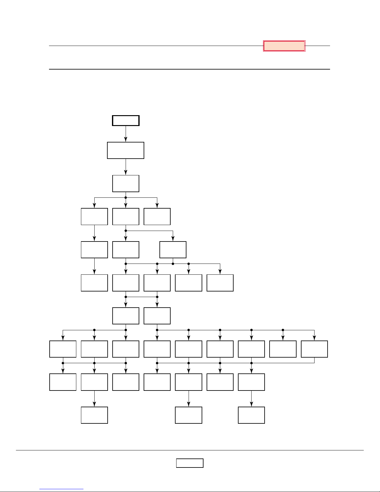
Replaceable P art Hierarc h y
The flow chart below shows what parts must be removed to access each replaceable part in the projector.
The parts on the first level (Ex. Lamp cover) are accessible without removing any other parts.
The move levels down that a part is, the more parts you need to remove in order to access it.
Lamp
SE board Lens cap AF board
Foot ADJ
Bottom
Top cover
Door SW
Lamp fan
Lens Intake fan
Key board
Enter key
Lamp cover
(Top)
Main
board
Network
board
Terminal
cover
Carrying
handle
Speaker
(L) (R)
Exhaust
fan
Main
power
Audio
board
Lamp
ballast
Thermal
SW
Power
supply fan
Optical
engine
DMD
board
DMD
chip
Lamp
bracket
Front
panel
Thermal
sheet
C/ W
board
AF
sensor
Color
wheel
Start
Chapter 2
2-2
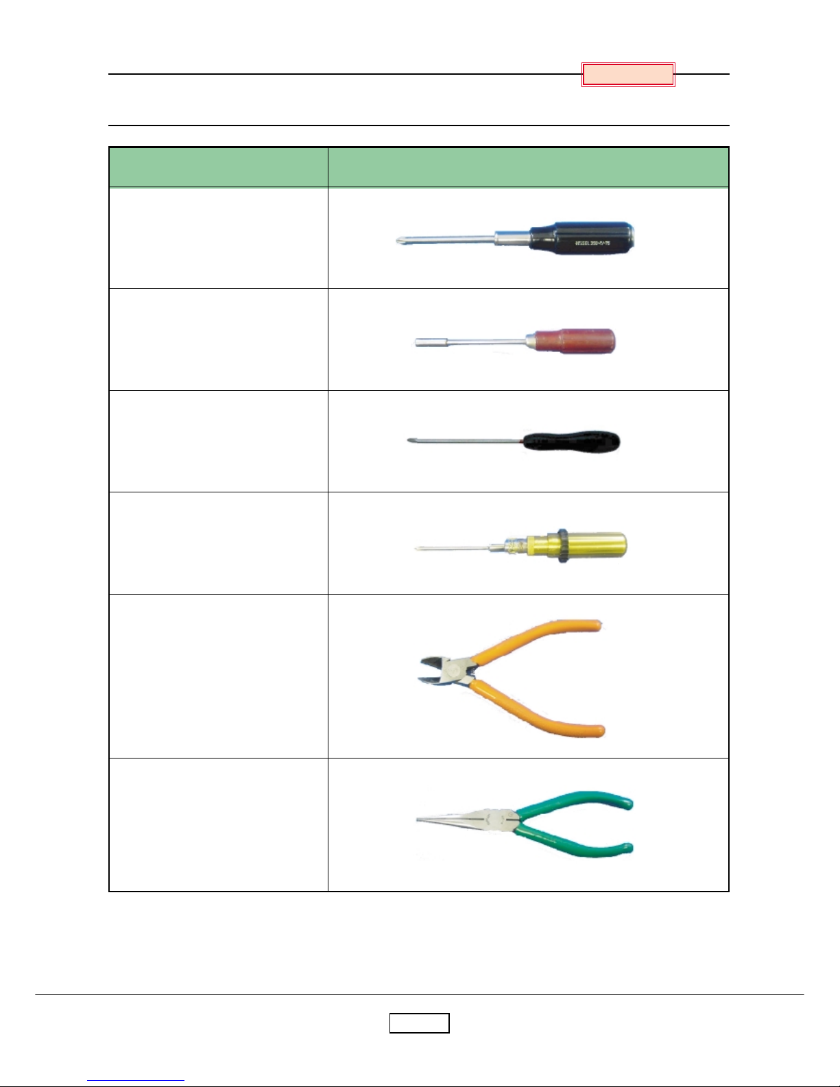
Required Tools
Item
Driver bit (+) No. 2
Box driver M3
Driver bit (+) No. 0
Torque driver bit (+) No. 2
Nippers
Cutting pliers
Photo
Chapter 2
2-3
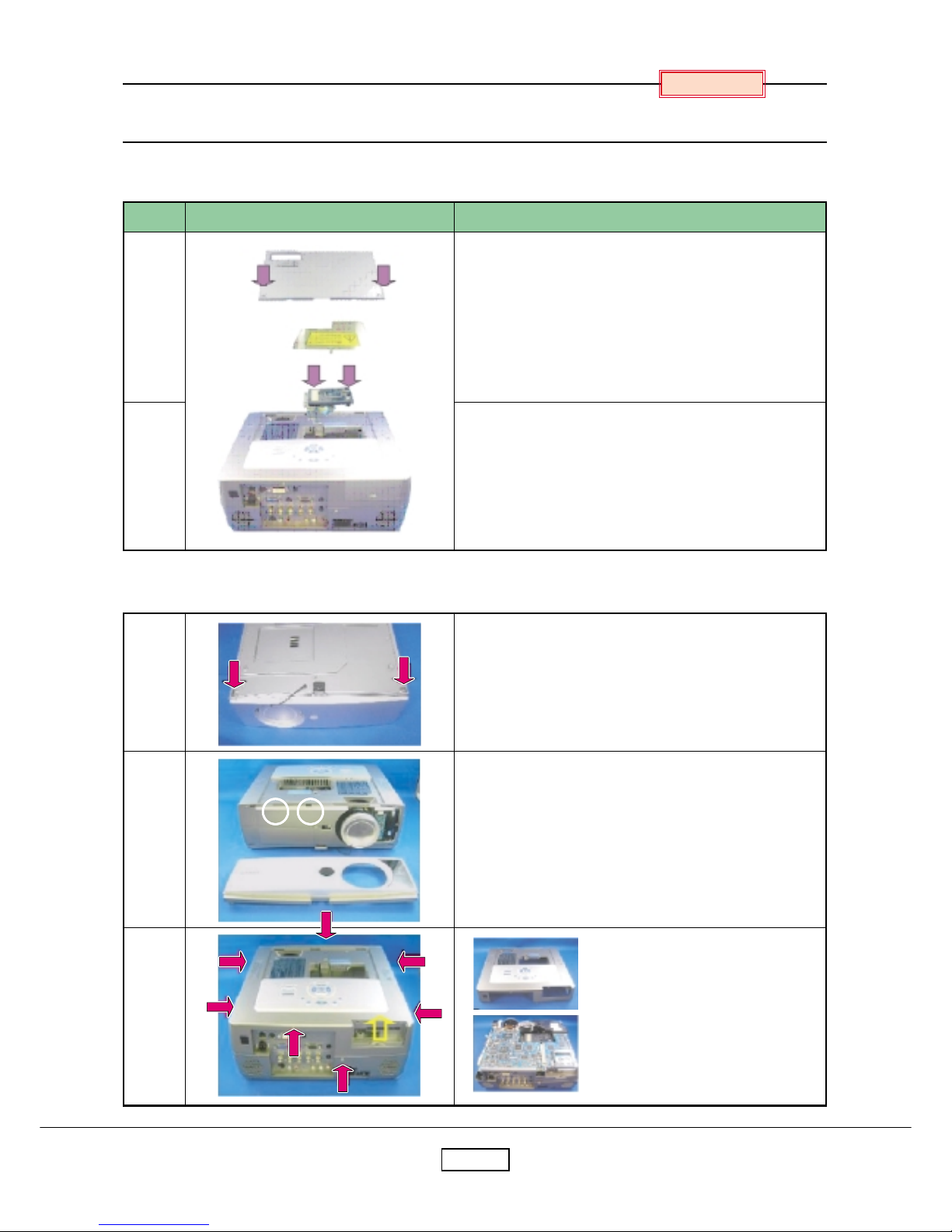
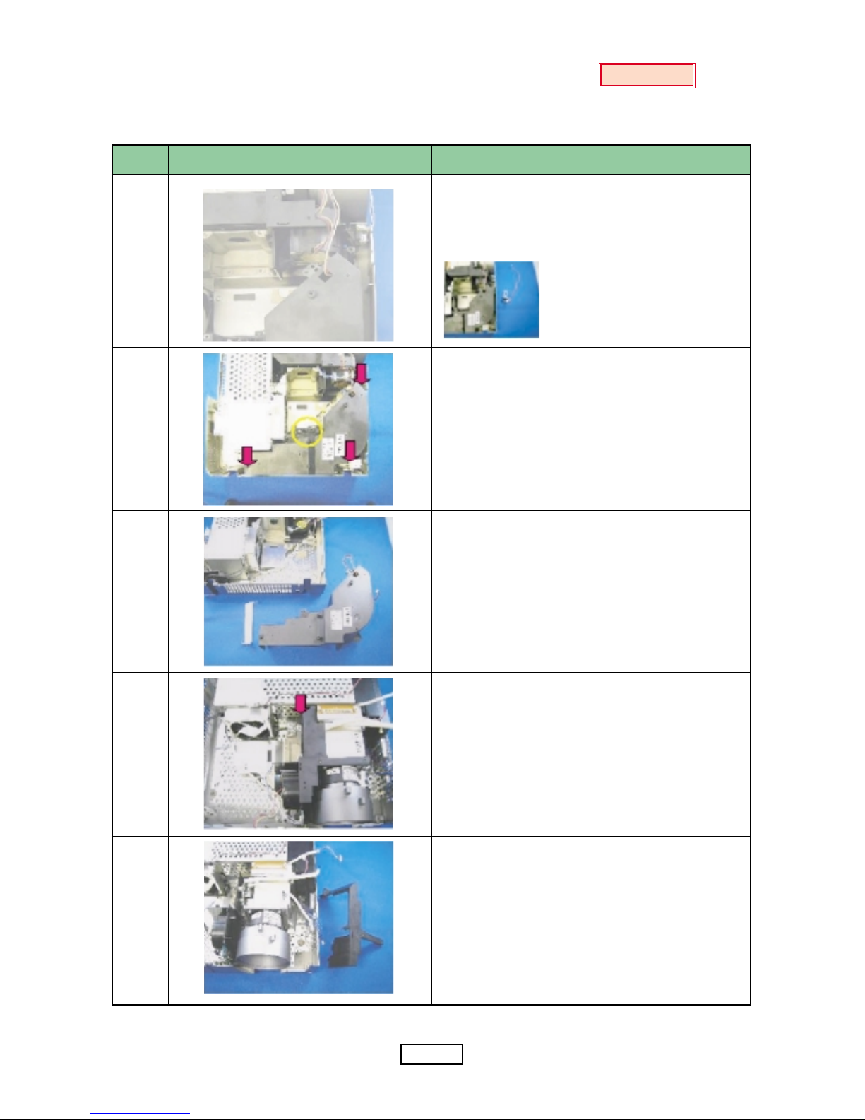
P arts Replacement
1. Lamp
2. Front / Top Cover
No.
1
2
Figure Explanation
Remove two lamp cover screws.
Remove three lamp screws.
Lamp is pulled out.
1
2
3
Remove two screws at the bottom.
Front cover is removed.
(There are two claws)
Remove seven screws.
Remove LAN card holder cover.
Top cover is removed.
Chapter 2
2-4
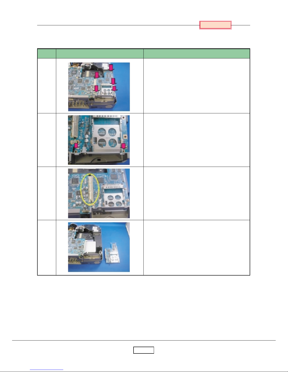
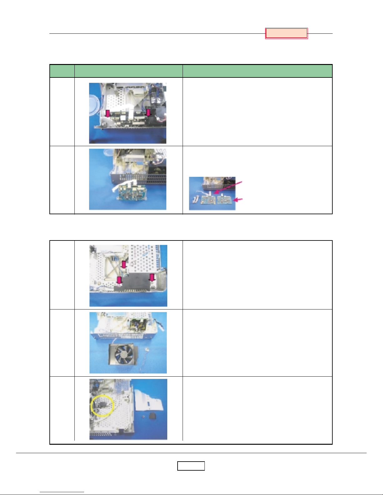
Chapter 2
No.
1
2
3
4
Figure Explanation
Remove five screws.
Remove two screws. (Drive bit (+) No. 0)
Three connectors are detached.
Remove Wireless LAN board.
3. Wireless LAN Board
2-5
Chapter 2
No.
1
2
3
Figure Explanation
All the connectors on a main board unit are removed.
(Marking is carried out and incorrect insertion is
prev ented, before removing a connector)
Remove five screws and two nuts.
Remove two screws at the bottom.
Main board is removed.
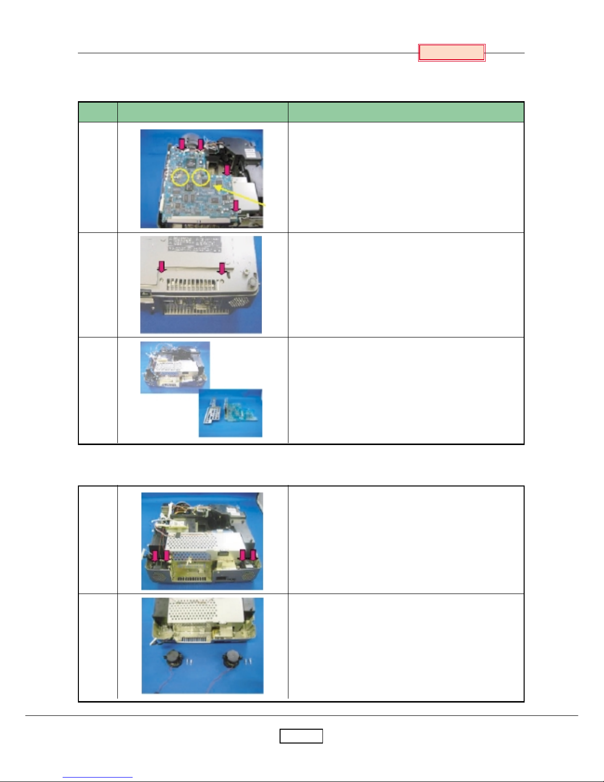
Main board and a terminal cover are separated.
(Two screws)
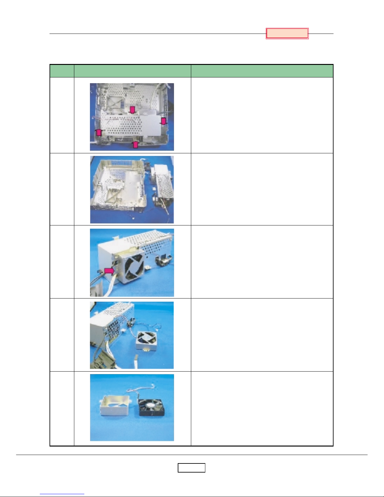
1
2
Remove four screws.
(Two each for right and left)
Speaker is taken out from a bottom cover.
4. Main Board
5. Speaker
2-6
Chapter 2
No.
1
2
3
4
5
Figure Explanation
Door SW Board is removed.(One screw)
Remove three screws.
Remove one screw for the connector to lamp
power supply .
Exhaust fan and duct block are taken out.
Remove one screw.
Plastics frame is removed.
6. Door Switch Board / Exhaust Fan / Engine Holder

2-7
Chapter 2
No.
1
2
Figure Explanation
Remove two screws.
Lamp fan and remote controller board block are
removed.
Lamp fan, remote controller board, and holder are
separated.
1
2
Remove five screws.
Engine block is taken out from the bottom cover.
7. Lamp Fan Block
8. Optical Engine
2-8
Chapter 2
1
2
3
Remove three screws.
Power supply fan and sensor board are taken out.
Metallic cover (two screws) and thermostat switch
(two screws) are removed.
9 . Autofocus Board / Audio Board
10. Intake Fan / Sensor Board
No.
1
2
Figure Explanation
Remove two screws.
Autofocus board & Audio board block is tak en out
from the bottom cover.
(Autof ocus board)
(Audio board)
2-9
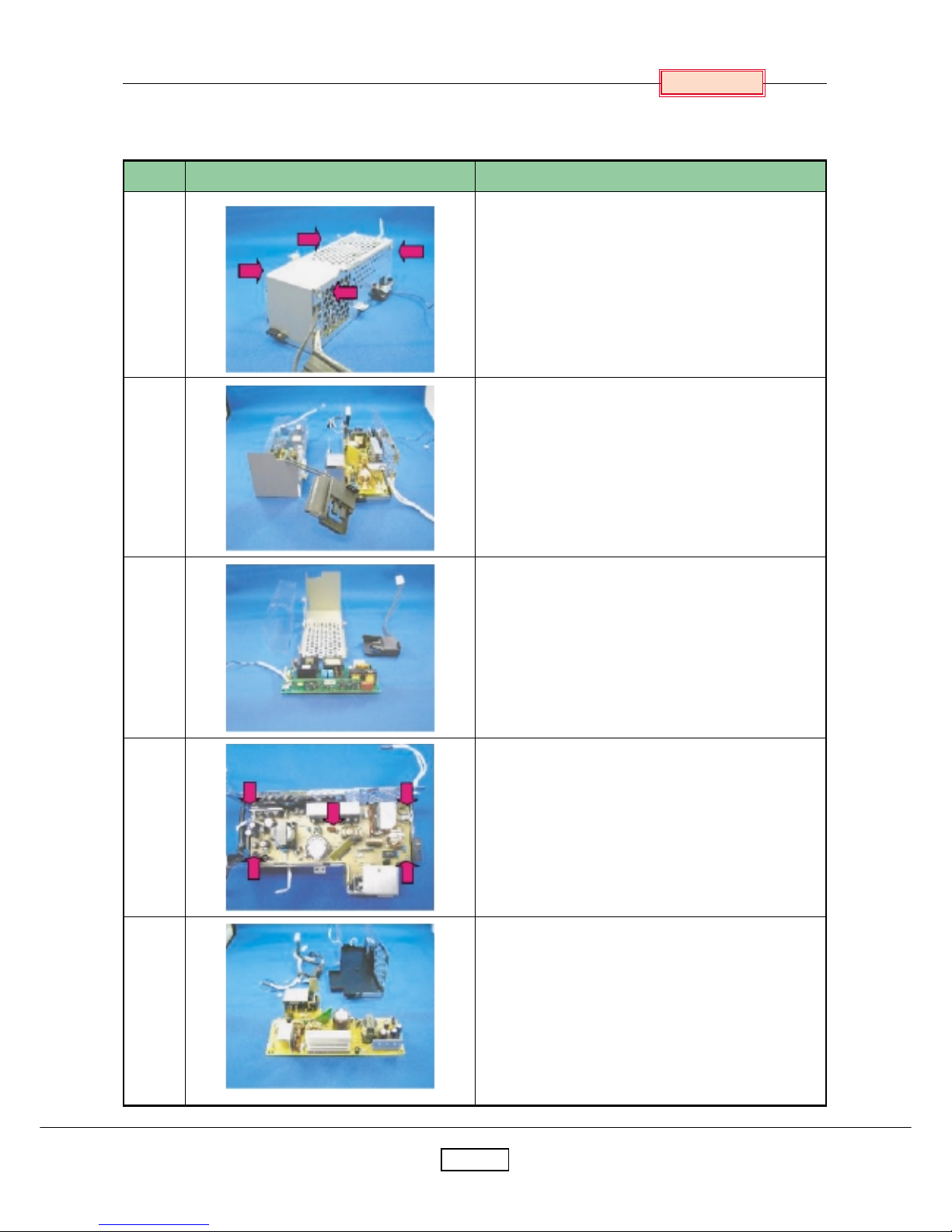
Chapter 2
No.
1
2
3
4
5
Figure Explanation
Remove four screws.
Power supply block is taken out.
Remove one screw.
Power supply fan is removed.
Fan holder and fan are separated.
11. Power Supply Block
2-10
Chapter 2
No.
1
2
3
4
5
Figure Explanation
Remove four screws.
Main power supply bloc k and lamp ballast block
are separated.
Lamp ballast, lamp connector, fr ame, and insulator are separated.
Remove five screws.
Main power supply unit and frame are separated.
12. Power Supply Block (Main / Lamp)
3-1
Chapter 3
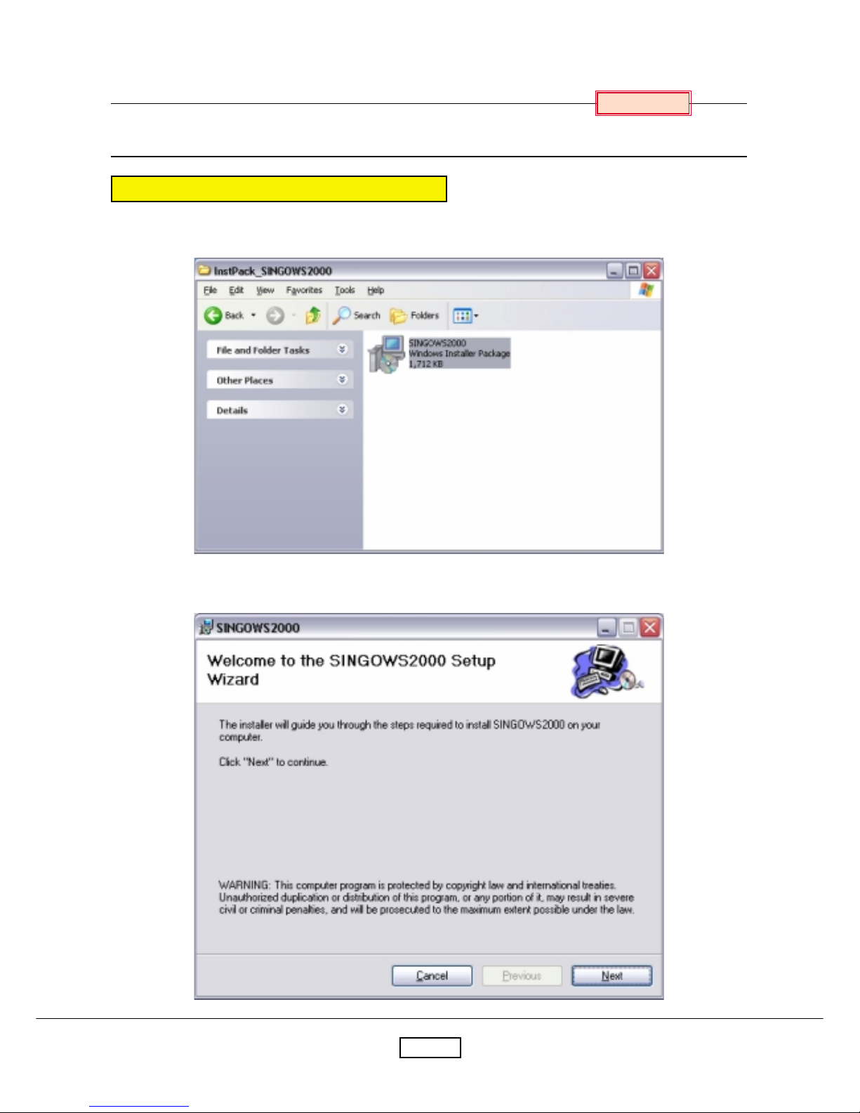
SINGOWS 2000
Install the Software on the Computer
The software you download is bundled into one .MSI file.
Double-click the file to install the signal generating software.
The Install Wizard appears, and start the install process.
Click the next button.
Chapter 3
3-2
Chapter 3
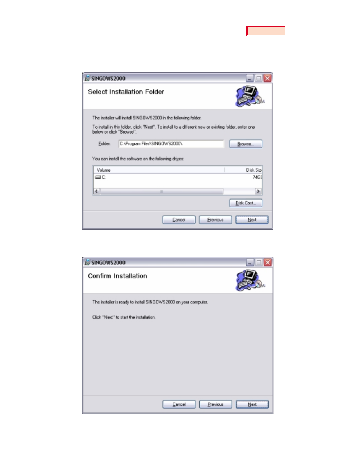
The Select Installation Folder dialog box appears .
Navigate to the location where you stored the software files.
Click the next button.
The Confirm Installation dialog box appears.
Click the next button.
3-3
Chapter 3
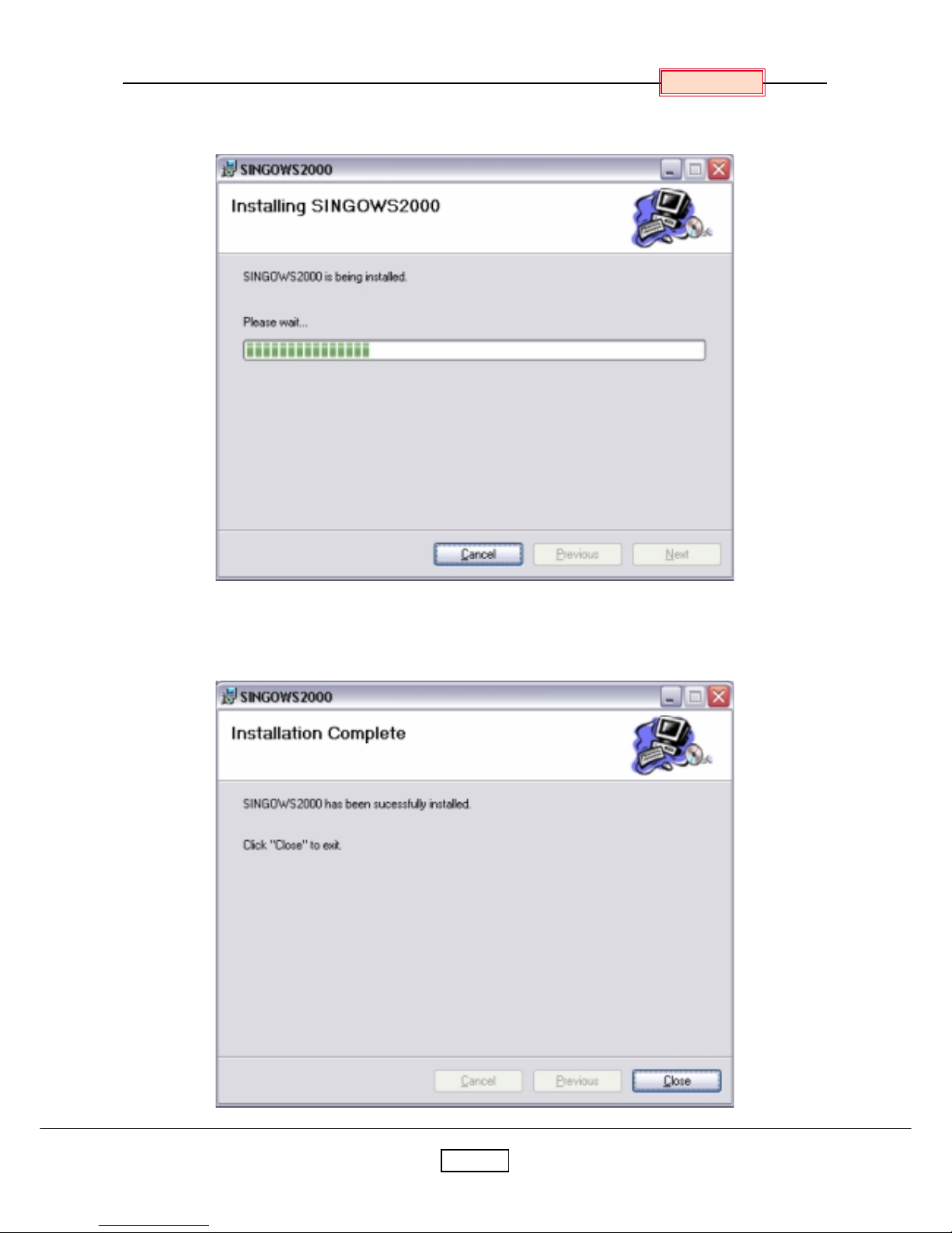
The Installing software dialog box appears.
The Installation Complete dialog box appears.
Click the Close button.
3-4
Chapter 3
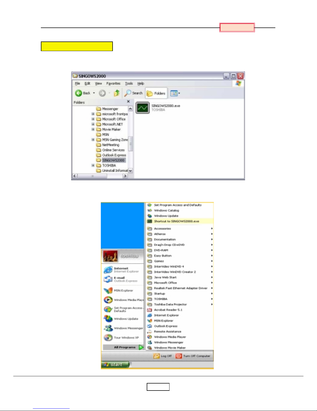
Startup the Software
Open Windows Exploler, navigate to the location where y ou stored the files, and then double click the
SINGOWS2000. exe.
Moreover, even if selecting the shortcut of the All programs of start, it can startup.
4-1
Chapter 4
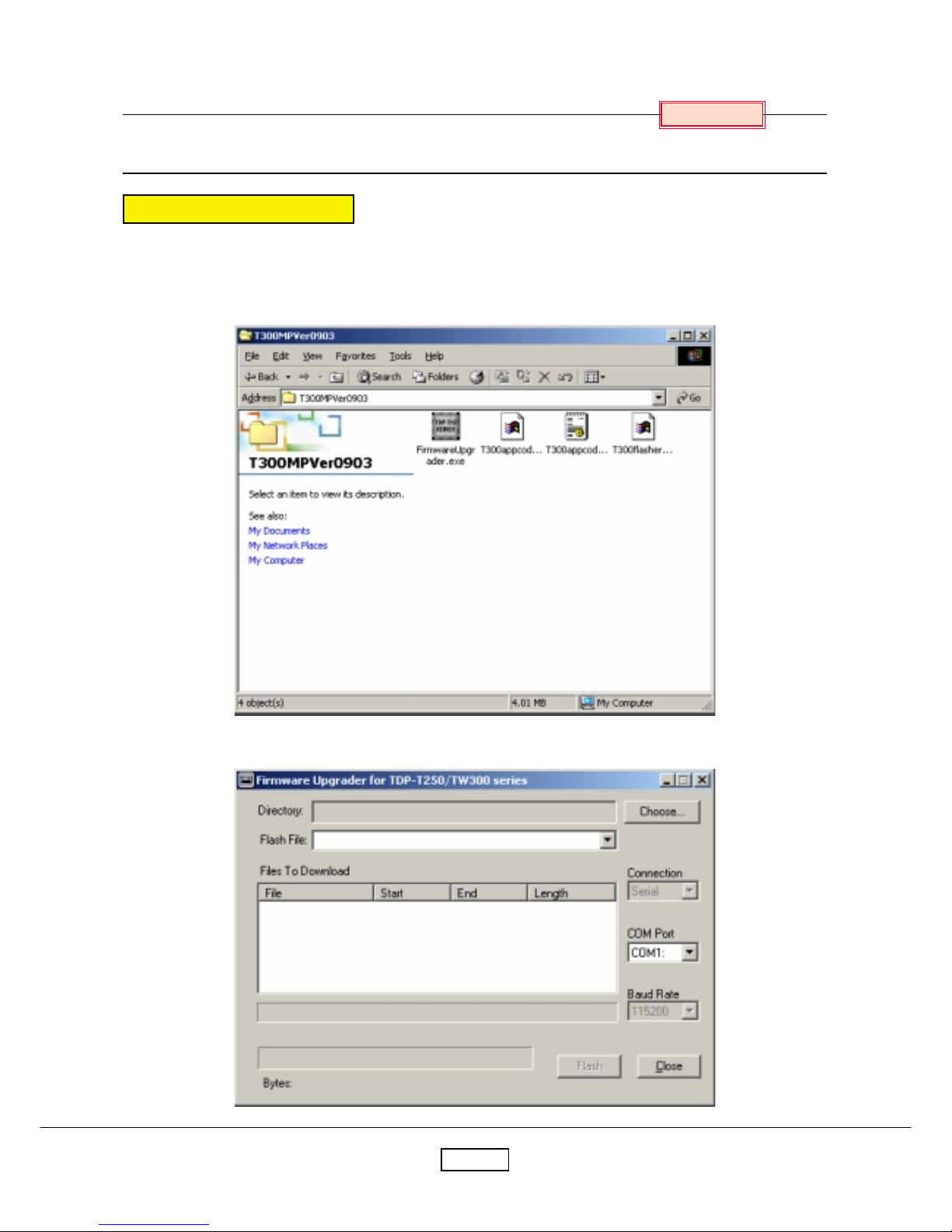
Firmware Upgrade
Upgrade the Firmware
Connect the control cable to the control terminal on the projector.
Then plug the RS232C connector on the other end of the cable into an RS232C port on the computer.
Open Windows Explorer navigate to the location where you stored the upgrade files, and then double click
the Firmware Upgrader. exe.
The Upgrade Wizard appears. Click the Choose button to open the Select File Dialog box.
Chapter 4
4-2
Chapter 4
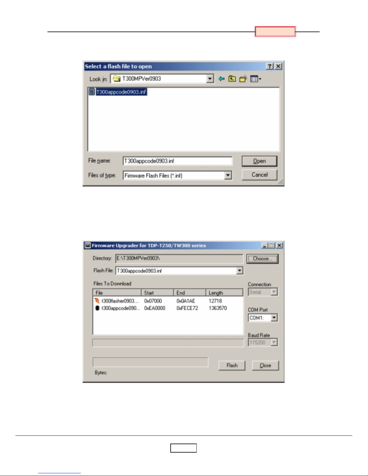
In the Open File dialog box, select the .inf file, and then click Open button.
The upgrade file appears in the Select File box.

4-3
Chapter 4
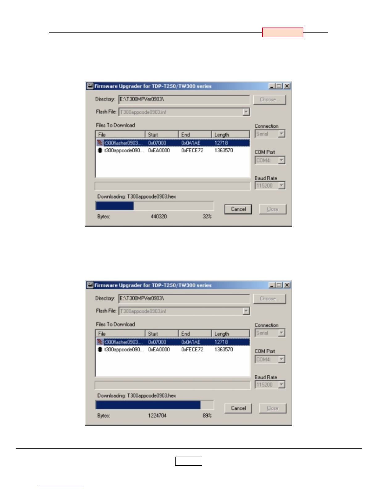
Select the COM port.
Click Flash button.
4-4
Chapter 4
Press and hold the projector’s [Input] and [Keystone] keys, and then plug in the power cord and turn on
Main power switch.
The projector starts the Firmware upgrade, [LAMP], [TEMP] and [FAN] LED’s are alwa ys RED blinking.
The computer begins downloading the upgrade files to the projector.
The process may take several minutes.
4-5
Chapter 4
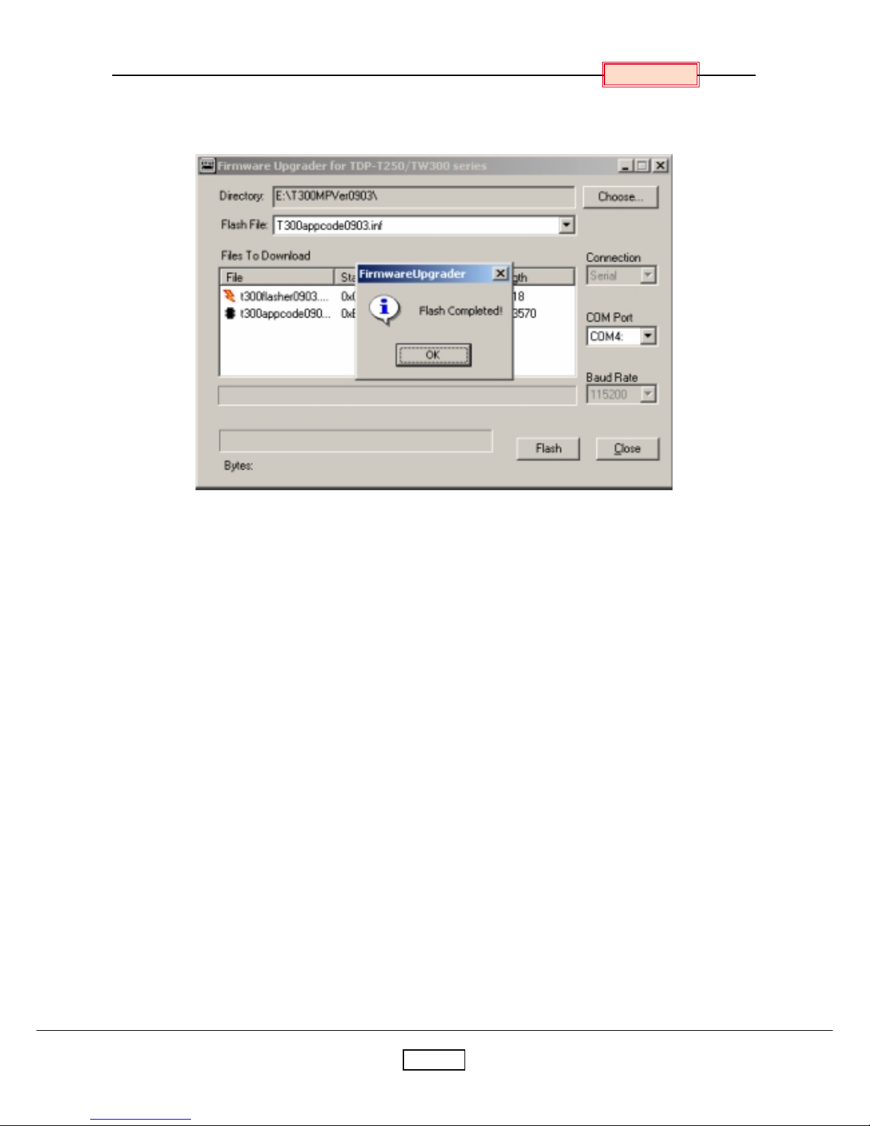
When the upgrade finishes normally, the following dialog bo x appears.
Click the Close button.
The upgrade is complete.
4-6
Chapter 4
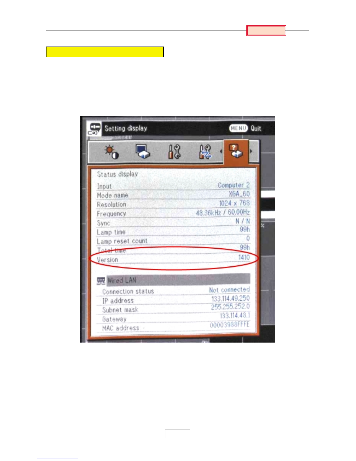
Confirm the Firmware Upgrade
1. Po wer up the projector.
2. On the projector keypad, press the MENU key to display the menus.
3. Press button Right or Left arrow to highlight Setting display.
4. The Setting display dialog box displays the software version.
These should match with the upgrade version y ou downloaded.
5-1
Chapter 5
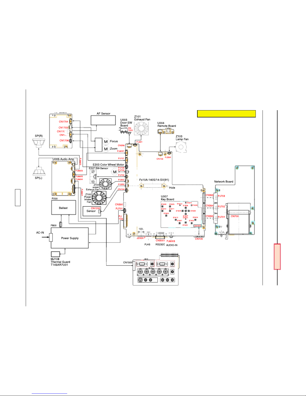
Wiring Diagram
Chapter 5
TW300 Wiring Diagram
 Loading...