


Unified Controller
nv Series
TC-net 100 (TN8) Module
Instruction Manual

Notes
(1)
The technical information provided herein describes typical operations and applications of the product and does
not guarantee the intellectual property rights or other rights of Toshiba or third parties nor allows license of its use.
(2)
No part or the whole of this document may be reproduced without prior consent.
(3)
The information herein may be changed in the future without notice.
(4)
All possible measures have been taken to prepare the information herein. If you have any question, comment, or
find any error, please contact us.
PROSEC, TOSLINE, TOSDIC, CIEMAC are trademarks or registered trademarks of Toshiba Corporation.
Microsoft, Windows are registered trademarks of Microsoft Corporation in the U.S. and other countries.
DeviceNet is a registered trademark of Open DeviceNet Vender Association Inc.
© TOSHIBA CORPORATION 2016
All rights reserved
i
Safety Precautions
Sign
Description
Symbol
Meaning
On the product and this operation manual, important information for safe and correct
use to prevent danger to the user and other people as well as property damage is
described.
Understand the following information (signs and symbols) before reading the text, and
follow the described items.
Description of signs
Indicates that failure to avoid it will result in an immediate risk of
DANGER
death or serious injury
(*1)
.
Indicates that failure to avoid it will result in a risk of death or
WARNING
serious injury
(*1)
.
Indicates that failure to avoid it will result in a risk of light or
CAUTION
*1: A serious injury indicates loss of sight, injury, burns (high/low temperature), electri c shock, brok e n bones, or into xatio n that will have aftereffects
and require hospitalization or lo ng-te rm ho spi tal visi ts for heali ng.
*2: An injury indicates an injury, burn, or electric shock that does not need hospitalization or long-term hospital visits for healing.
*3: A property damage indicates consequential damage in terms of breakage of properties or materials.
medium injury
(*2)
or only property damage
(*3)
.
Description of symbols
Prohibited
Mandatory
Warning
(Note) Descriptions of Prohibition, Mandatory Action, and Warning vary depending on the display on the main unit.
Indicates “Prohibition” or “You must not do”.
Specific details are indicated near the symbol
Indicates “Mandatory Action” or “Do as indicated”.
Specific details are indicated near the symbol
Indicates Warning.
Specific details are indicated near the symbol
Unified Controller nv series TC-net 100 (TN8) Module Operation Manual
with pictures and text.
with pictures and text.
with pictures and text.
ii
Install the device in a place where
1. Safety Precautions on Installation
Ground
Prohibited
Ground the device.
Otherwise, it may cause an electric
shock or fire.
Do not install, store, or use it in
the following environments.
・ A place with a lot of dust
WARNING
Mandatory
CAUTION
Construct the emergency stop
circuit and interlock circuit
outside
the nv series.
Otherwise, it may cause an injury
accident or damage to the machine if
failure or malfunction occurs in the
nv
series.
Otherwise, it may cause accidents.
・ A place with corrosive gases (SO2,
H2S) ore flammable gases
・ A place with vibrations and shocks
exceeding the allowed values
・ A place with condensations due to
rapid temperature changes
・ A place with low or high
temperature outside of the
installation condition
・ A place with high humidity outside
of the installation condition
・ A place with direct sunlight
・ A place near equipment
generating strong radio waves or
magnetic fields
It may cause accidents.
maintenance and inspection can
Mandatory
6F8C1360
be done easily.

iii
conditions and methods
Prohibited
Mandatory
Do not block the ventilation hole
or air inlet/outlet.
It may cause fire or failure due to
overheat.
For installation and wiring of the
system, observe the installation
described in this document.
Otherwise, it may cause a fall, fire,
failure, or malfunction.
Unified Controller nv series TC-net 100 (TN8) Module Operation Manual
iv
2. Safety Precautions on Maintenance and Inspection
Mandatory
Prohibited
Mandatory
When installing or removing the
module after wiring, make sure
that the external power supply is
of f.
Otherwise, there will be live electric
poles on the back of the external
terminal block of the module,
causing an electric shock.
Do not drop, crush, or apply
strong shocks to the device or
board.
It may cause failure.
Before touching the device or
board, touch a grounded metal
to discharge the static electricity
of your body.
Otherwise, it may cause malfunction
or failure due to static electricity.
WARNING
CAUTION
Mandatory
Prohibited
Place a board or module
removed from the unit or base
unit on a conductive mat or
conductive bag (used for a
backup board) on a grounded
table.
Otherwise, parts may be
damaged due to static electric ity.
Do not use benzene or thinner to
remove stain on device, module,
or board.
Mandatory
Wipe off stain on the device,
module, or board with a soft
cloth.
For severe stain, use a wet cloth
wrung tightly.
Leaving them stained may cause
wrong decision or malfunction.
It may cause deformation or
discoloration of the device panel,
module, or board.
6F8C1360

v
Do not touch the terminals of the
Do not modify, repair,
disassemble, or adjust the device,
Before using, check that the
Do not touch the terminals of the
3. Safety Precautions on Replacement of Life Limited Parts
WARNING
Mandatory
If the device has power fuses or
alarm fuses, when replacing
them, turn off the switch of the
device.
Otherwise, it may cause an electric
shock or fire.
4. Safety Precautions on Daily Use
Mandatory
No touch
module and unit during
energization.
It may cause an electric shock.
WARNING
When the ambient or internal
temperature of the device rises
abnormally or failure occurs in
the device, stop using the device,
turn off the power, and contact
one of Toshiba's service
representatives.
Prohibited
module, or board.
It may cause an electric shock, fire,
injury, or failure.
Upon faulty operation or failure,
contact Toshiba's branch office or
service offices.
power capacity, frequency,
Mandatory
voltage, and regulation comply
with the device specifications.
If not, it may cause damage of the
device, or fire due to overheat, as
well as not obtaining the original
performance of the device.
Using it as it is may cause fire due to
overheat.
No touch
energization.
module and unit during
It may cause an electric shock.
The power supply module is for the nv
series only. Do not use it alone for
any other purposes.
Unified Controller nv series TC-net 100 (TN8) Module Operation Manual
vi
Do not touch anything other than
Do not disassemble or modify
Do not forcefully bend, pull, or
Prohibited
Prohibited
the operation part (setting
switches inside the module), such
as the IC parts and terminals,
connectors, and soldered
surfaces inside the module.
Doing so may result in electrostatic
breakdown of the ICs and LSIs,
causing failure. Also, an injury may
occur due to the ends of the part lead
wires, or burns may occur due to hot
parts.
the device or module.
It may cause malfunction or failure as
well as loss of safety of the device.
CAUTION
Prohibited
Prohibited
twist the power cord and cables.
It may cause breaks or heating.
Do not insert any metal into the
gaps of the device main body.
It may cause fire.
5. Safety Precautions on Transportation, Storage, and Disposal
Observe ordinances and rules.
When destroying the product,
Mandatory
observe the ordinances and rules of
the local government.
CAUTION
Prohibited
For transportation and storage of
the product, use a conductive
bag and packaging box.
Otherwise it will cause failure.
6F8C1360

vii
Restrictions on Application
This product is not developed/manufactured for use in systems involving devices that
directly affect human life (Note 1). Do not use them for such applications.
To use this product for systems that involve devices that significantly affect human
safety or maintenance of public functions (Note 2), special considerations (Note 3)
are required in system operation, maintenance, and management. In this case,
contact one of Toshiba's sales representatives.
(Note 1) Devices that directly affect human life include the following.
• Medical devices such as life supporting devices and devices for surgical
units.
(Note 2) Systems that involve devices that significantly affect human safety or
maintenance of public functions include the following.
• Main unit control systems of nuclear power plants, safety protection
systems of nuclear facilities, and other systems that are critical for safety
• Operation control systems of mass transportation systems and air traffic
control systems
(Note 3) Special considerations indicate sufficient discussions with Toshiba's
engineers to construct a safe system (e.g. employing fool-proof design,
fail-safe design, or redundant design).
Disclaimer
Toshiba shall not be responsible for any damage caused by fire or earthquake, acts of
a third party, other accidents, the user's willful acts or negligence, misuse, or use in
abnormal conditions.
Toshiba shall not be responsible for any incidental damage (loss of business profits,
interruption of business, change or loss of stored memory) caused by use of or being
unable to use this product.
Toshiba shall not be responsible for any damage caused by failure to observe the
information described in the operation manual.
Toshiba shall not be responsible for any damage caused by malfunctions due to
combination with any connected device.
Toshiba shall not be responsible for any damage caused by malfunctions due to
combination with any application program created by the customer.
Note
Use your cellular phone or PHS 1 meter or more away from the product main unit in operation,
various transmission cables, and I/O bus cable. Otherwise, the system may malfunction.
6F8C1360

viii
Introduction
This manual describes the functions, methods of installation and setting, and
maintenance and inspection of the TC-net 100 (TN8) module ("TN8 module" hereafter)
for connecting the information/control network TC-net 100 to the Unified Controller nv
series.
To use this device correctly, read "Safety precautions" first.
The manuals related to the TN8 module are as follows.
• Unified Controller nv series Main Unit Operation Manual (6F8C1220)
Describes the main unit hardware of the nv series controller.
• Unified Controller nv series Type 1 Function Manual (6F8C1221)
Describes the functions and basic use of the nv series Type 1.
• Unified Controller nv series Type 2 Function Manual (6F8C1362)
Describes the functions and basic use of the nv series Type 2.
• Unified Controller nv series/Integrated Controller V series Command Manual
(6F8C1226)
Describes the detailed specifications of the instruction words of the program
languages (LD, FBD, and SFC) supported by the nv series and Integrated Controller
V series.
• Unified Controller nv series/Integrated Controller V series nV-Tool (Basic)
Operation Manual (6F8C1290)
Describes how to create, debug, print, and save programs using nV-Tool.
• Unified Controller nv series TC-net 100 Module Manual (6F8C1360)
(This document)
Describes the TC-net 100 (TN8) module, which is common to Type 1 and Type 2
of the nv series.
After reading the manual, place it in a location that can be accessed easily when
necessary.
6F8C1360

ix
●
Describes what the user should be particularly aware of to handle the product correctly.
Describes what the user should observe to handle the product correctly.
Describes a remark.
●
Notational conventions
The following are the notational conventions for better understanding of this
document.
Important:
Note:
Remark:
Reading this document
This document consists of the following chapters.
•Chapter 1 Introducing the TN8 module
Describes the functions, characteristics, and names and functions of the
parts.
•Chapter 2 Installation and wiring
Describes how to install it to the basic unit and how to connect cables.
•Chapter 3 Setting
Describes how to set the switches and parameters to use the module
correctly.
•Chapter 4 Operation
Describes the operations such as checking before operation, startup, and
shutdown.
•Chapter 5 Troubleshooting
Describes troubleshooting such as what to do when failure occurs.
•Chapter 6 Maintenance and inspection
Describes troubleshooting regarding daily inspection and periodical
inspection and how to perform inspections.
•Chapter 7 Application interface
Describes the user application interface and usage constraints.
Unified Controller nv series TC-net 100 (TN8) Module Operation Manual

x
Chapter 1
Introducing the
TN8
Chapter 2
Installation and
W
Chapter 3
Setting
CONTENTS
1.1 Functions and Characteristics of the TN8 Module ······ 2
1.2 Names and Functions of the Parts ··························· 4
1.2.1 Names of the parts ·············································· 4
Module
1.2.2 Functions of the parts ··········································· 5
iring
6F8C1360
...1
...7
...15
2.1 Installation (Installation to the Basic Unit) ················· 8
2.2 Connecting the TC-net 100 Cable ·························· 10
2.3
Connecting the Serial Communication Port (RS-232C)
································································ 12
Cable
2.4 Replacing the Module ·········································· 13
3.1 Switch Setting ·················································· 16
3.1.1 Station address setting switch
(STN-H, STN-L) ················································ 16
3.1.2 Operation mode setting switch (MODE) ·················· 17
3.2 Network Parameter Setting ··································· 18
3.2.1 Networ k ID and subnet mask ······························· 18
3.2.2 Station address ················································· 19
3.2.3 Overview of multicast address ······························ 19
3.3 Setting with the Engineering Tool ·························· 21
3.3.1 Network parameter setting ··································· 22
3.3.2 Setting the sc an sending bloc ks ····························
3.3.3 Setting the st a te change not i fi cation ·······················
3.4 Network Information ··········································· 38
3.4.1 Referrin g to LAN tran smi ssion map ······················· 38
3.4.2 Accessing the scan data ····································· 39
3.4.3 Clearing the scan unhealthy state ·························· 39
3.4.4 Clearing the overlapping sendi ng SA ····················· 39
3.4.5 LAN control information ······································ 40
3.4.6 Detailed explanation of LAN management information 41
3.4.7 MIB information ················································· 42
3.4.8 Reception system switching ································· 43
3.4.9 Viewing the in-ring map······································· 44
3.5 Option Functions ················································ 45
3.5.1 Setting the self healthy mode parameters ················ 45
3.6 Setting the RAS Information Block in Scan
Transmission ····················································· 47
32
35

xi
Chapter 4
Operation
Chapter 5
Troubleshooting
Chapter 6
Maintenance and
I
Chapter 7
Application
I
Appendix A
Specifications
nspection
...49
...51
...53
6.1 Inspection ························································· 54
6.1.1 Daily inspection ················································· 54
6.1.2 Periodical inspection ·········································· 55
6.2 Life Limited Parts ··············································· 55
nterface
...57
7.1 Information by Socket ········································· 59
7.1.1
7.1.2 Referring to information by socket ························· 60
7.1.3 T iming of generation of information by socket ··········· 61
Configuration of information by socket
······················ 59
7.2 Transmission Path Diagnosis Information ·············· 63
7.2.1 Configu ration o f the s can dat a healthy map ············· 63
7.2.2 Configu ration o f the s can dat a unhealthy map ··········
7.2.3 Configuration of the scan data talker map ················
7.2.4 Configu ration o f RAS in formation ··························
7.2.5
Configuration of in-ring map ···································· 68
64
65
66
7.3 Usage Constraints ·············································· 69
7.4 Restriction on Station Redundant Configuration ······ 70
A.1 General Specifications ········································ 72
A.2 TC-net 100 Transmission Specifications ················· 73
A.3 Function Specifications ······································· 74
...71
A.4 Serial Communication Port (RS-232C) Transmission
Specifications ···················································· 75
Unified Controller nv series TC-net 100 (TN8) Module Operation Manual

xii
Appendix B
Outside
D
Appendix C
Related Products
Appendix D
Decimal-hexadecimal
C
imensions
...77
...79
onversion Table
...81
6F8C1360

1
Chapter 1 Introducing the TN8 Module
This chapter describes the functions, characteristics, and names and
functions of the TN8 module
1.1 Functions and Characteristics of the TN8 Module ··· 2
1.2 Names and Functions of the Parts ····················· 4
1.2.1 Names of the parts ·································· 4
1.2.2 Functions of the parts ······························· 5

Chapter 1 Introducing the TN8 Module
2
•
TN821A/TN822A are successor machine for TN821/TN822. Thus, TN821A/TN822A are
Remark
PCMP: Process Control Message Protocol
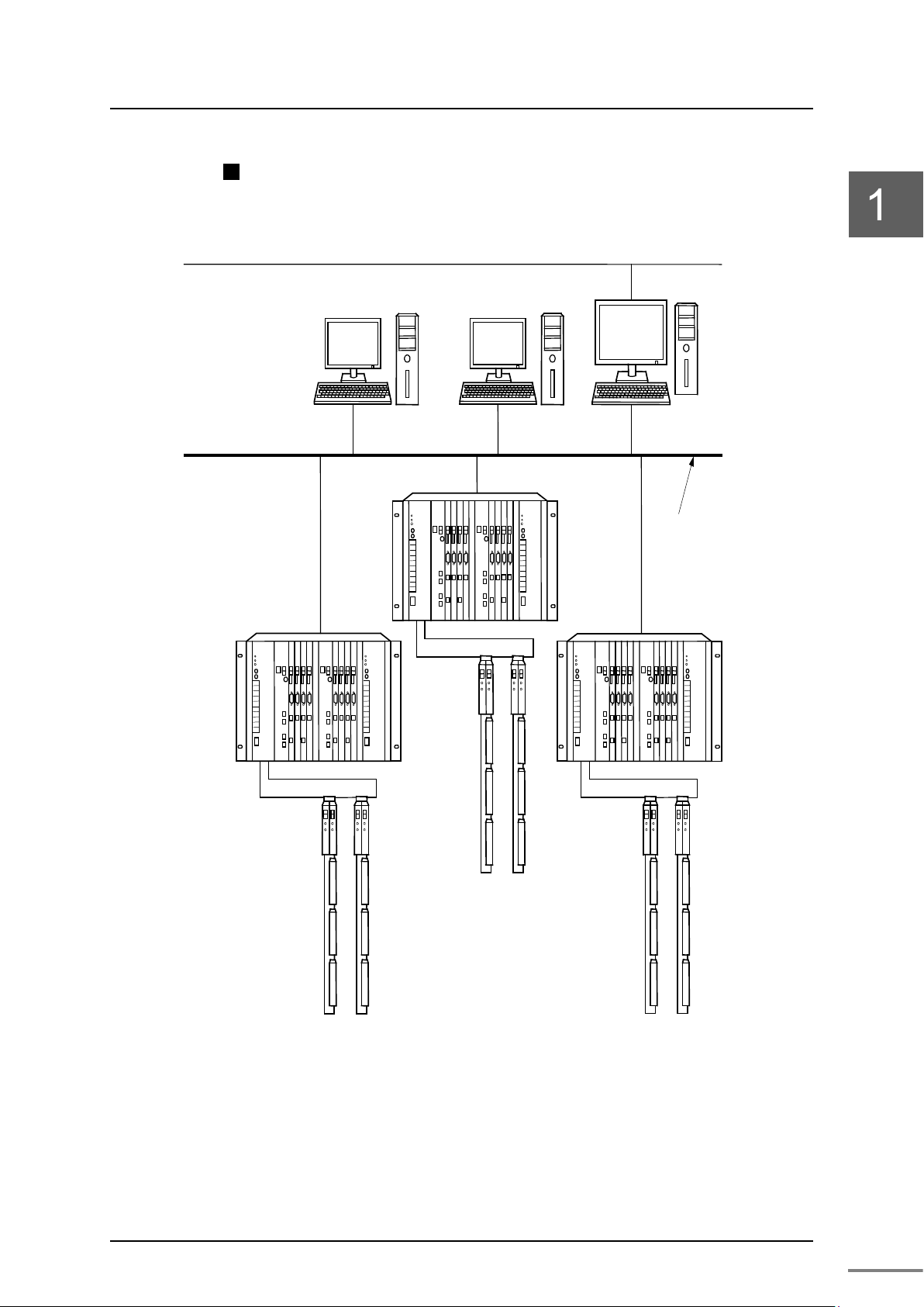
1.1 Functions and Characteristics of the TN8 Module
The TN8 module is a device to connect the controller main unit of
the Unified Controller nv series to the information and monitoring
control network TC-net 100. For the interface of the TN8 module,
optical fiber cables are provided: One for single bus and one for
dual-redundant bus.
・TN821: Optical fiber cable single bus module
・TN821A: Optical fiber cable single bus module
・TN822: Optical fiber cable dual-redundant bus module
・TN822A: Optical fiber cable dual-redundant bus module
Up to 4 TN8 modules can be installed to the basic unit.
Remark
compatible with TN821/TN822.
Characteristics of the TN8 mo dule
• Openness
The TN8 module is a network for monitoring control that
maintains the openness of the 100 Mbps Ethernet and has the
collision avoidance function and deterministic real time
responsiveness.
• Communication services
The communication services include scan transmission (cyclic
broadcast transmission) that transmits control data periodically,
and normal message transmission.
Scan transmission has 3 modes; high, medium and low, which can
be assigned according to the data update cycle to ensure
deterministic real time responsiveness.
Message transmission supports Toshiba's standard protocol
PCMP as well as TCP, UDP, and IP.
•
• High reliability
Highly reliable system configuration is available with redundancy
of the transmission path.
6F8C1360
1.1 Functions and Characteristics of the TN8 Module
3
Host system
network
Unified Cont roller nv series
TC-net I/O system
TC-Net 100
Monitoring control newwork
Example of system configuration
Figure 1-1 System configuration example (Optical transmission path)
Unified Controller nv series TC-net100 (TN8) Module Operation Manual
Chapter 1 Introducing the TN8 Module
4
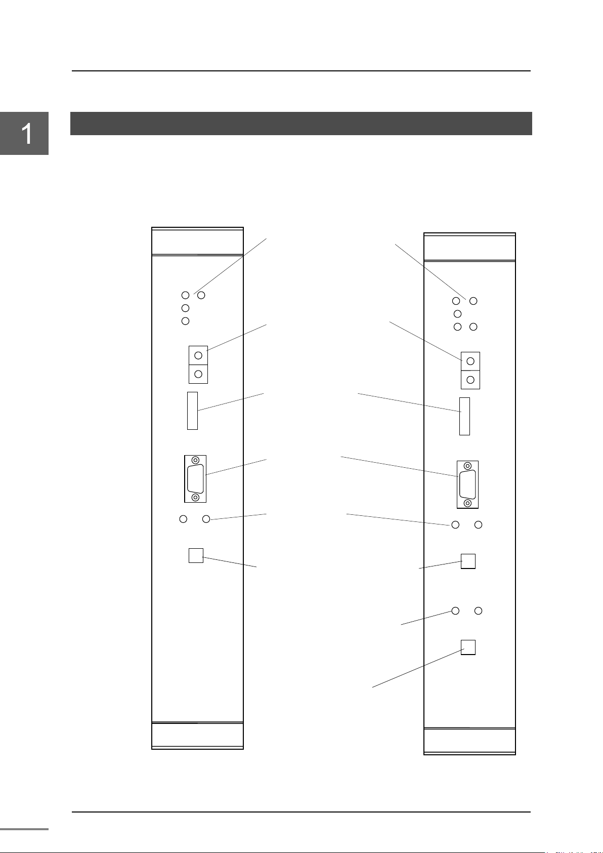
State display LED
・RUN
・ERR
・
A
・SCAN
Station address setting switch
・
・STN L
Operation mode setting switch
・
Serial communication port
・
State display LED(A system)
・
A
・
A
TC
RUN
ERR
L
SCAN
MODE
UN
H
L
STN
TOOL
TN822
L-B
TN-A
LNK-A
ACT-A
TN-B
LNK-B
ACT-B
Optical fiber cable
RUN
ERR
L-A
SCAN
MODE
UN H L
STN
TOOL
TN821
TN-A
LNK-A
ACT-A
Optical fiber cable
For single bus
State display LED
・RUN
・ERR
・
A
・
B
・
CAN
・
A
・
A
TC
State display LED
for B System
TN
For dual-redundant bus
1.2 Names and Functions of the Parts
1.2.1 Names of the parts
821/TN821A
TN822/TN822A
L-
LLS
STN H
MODE
TOOL
LNKACT-
-net 100 modular connector for A system
-A
Figure 1-2 Names of the parts of the TN8 module (TN821/TN821A, TN822/TN822A)
6F8C1360
(B system)
LNKACT-
-net 100 modular connector
(Note) Front panel name is difference between TN821A/TN822A and TN821/TN822.

5
1.2.2 Functions of the parts
Normal
RUN
Displays the hardware operation state.
ON
ERR
Displays the hardware operation state.
OFF
SCAN
Displays the scan transmission state.
SCAN
L-A (green)
Displays the TC-net 100 A system state.
ON
L-B (green)
Displays the TC-net 100 B system state (TN822 only).
ON
LNK-A
Displays the TC-net 100 A system link state.
ON
ACT-A
Displays the TC-net 100 A system frame transmission
Blinking
LNK-B
Displays the TC-net 100 B system link state (TN822
ON
ACT-B
Displays the TC-net 100 B system frame transmission
Blinking
The major functions of the parts are as shown below.
State display LED
Table 1-1 Display details on the state display LED and normal display
1.2 Names and Functions of the Parts
Name Display
(green)
(red)
(green)
(green)
ON: Running
OFF: Down
ON: Down
OFF: Running
ON: SCAN transmission is in execution.
OFF: SCAN transmission is under suspension.
ON: TC-net 100 transmission is in execution.
OFF: TC-net 100 transmission is under suspension.
ON: TC-net 100 transmission is in execution.
OFF: TC-net 100 transmission is under suspension.
ON: Connected to the hub successfully.
OFF: Not connected to the hub.
(green)
state.
Blinking: TC-net 100 frame transmission is in execution.
OFF: TC-net 100 transmission is under suspension.
display
ON during
transmission
(green)
only).
ON: Connected to the hub successfully.
OFF: Not connected to the hub.
(green)
state (TN822 only).
Blinking: TC-net 100 frame transmission is in execution.
OFF: TC-net 100 transmission is under suspension.
(Note) 1.Check the LED states from the front.
2.Refer to “Table 5-1 Diagnosis using the LEDs.
”
Unified Controller nv series TC-net100 (TN8) Module Operation Manual

Chapter 1 Introducing the TN8 Module
6
Station address setting switch (STN-H, STN-L)
Switches to set the station address in hexadecimal. For setting method,
refer to "Chapter 3 Setting."
Operation mode setting switch (MODE)
Switches to set the operation mode. For setting method, refer to
"Chapter 3 Setting."
Serial communication port RS-232C (TOOL)
A RS-232C port for maintenance. The connector is a 9-pin D-sub
connector (socket).
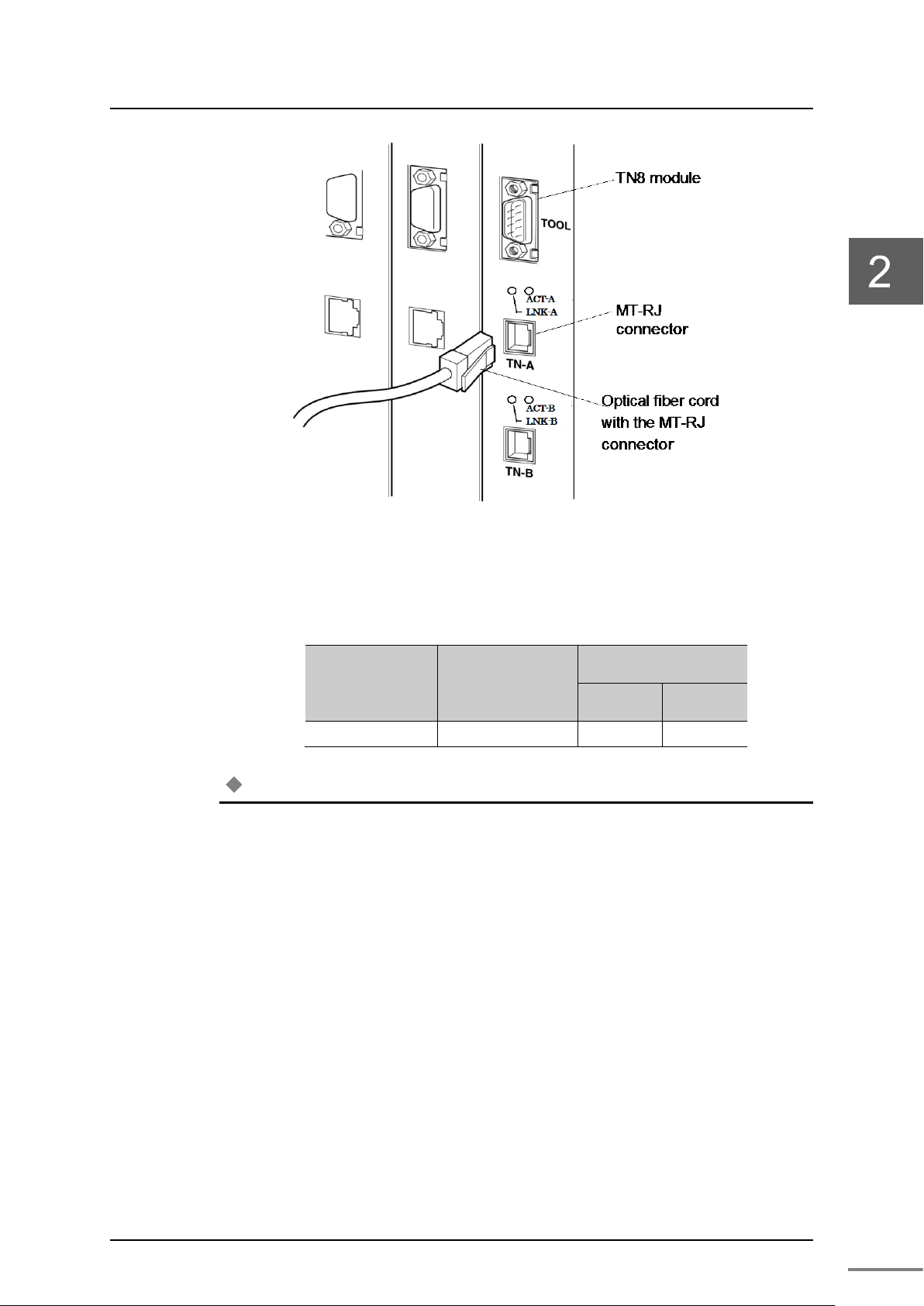
TC-net 100MT-R J connectors (TN-A and TN-B)
A communication port for the TC-net 100. The optical fiber cord with
the MT-RJ connector is connected to it.
6F8C1360

7
Chapter 2 Installation and Wiring
This chapter describes installation and wiring methods of the TN8 module.
Before installation and wiring, read this operation manual thoroughly.
2.1 Installation (Installation to the Basic Unit) ··············· 8
2.2 Connecting the TC-net 100 Cable ························· 10
2.3 Connecting the Serial Communication Port (RS-232C)
Cable ····························································· 12
2.4 Replacing the Module ······································· 13
Chapter 2 Installation and Wiring
8
Before installing or removing the module,
make sure that the basic unit to which th
module is installed is turned off.
Otherwise, it may cause an electric shock.
Do not touch the interior of the product except
the switches.
It may cause an electric shock.
Install it under an environm
the product specifications.
When installing it under an environment that does
not satisfy the product operating temperature range,
apply forced cooling with cooling equipment.
Operating temperature range: 0 to 55
C
Before installation or wiring, remove the static
electricity from your body.
The static electricity accumulated in the human body
may cause failure of the product.
Do not touch the cables carelessly.
Applying stress to the cabl
or accidents.
When installing the product to the basic unit,
do not bend the pins of the station bus
connector.
If it is difficult to insert the module to the basic
unit, remove it
forcing it.
CAUTION
Use a Phillips screwdriver.
To prevent damage to the screws, use a screwdriver
that is suitable for the screws.
CAUTION
Perform a notification check in the application
le
Mandatory
2.1 Installation (Installation to the Basic Unit)
WARNING
e TN8
Mandatory
WARNING
Prohibited
ent that satisfies
CAUTION
°
Prohibited
CAUTION
Prohibited
CAUTION
CAUTION
CAUTION
6F8C1360
es may cause malfunction
once and try again rather than
vel using the transmission protocol.
Prohibited
Prohibited
Prohibited
Prohibited
2.1 Installation (Installation to the Basic Unit)
9
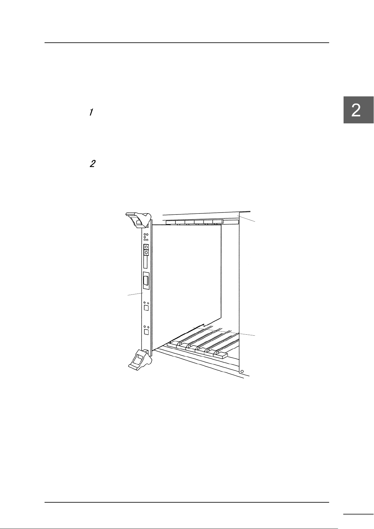
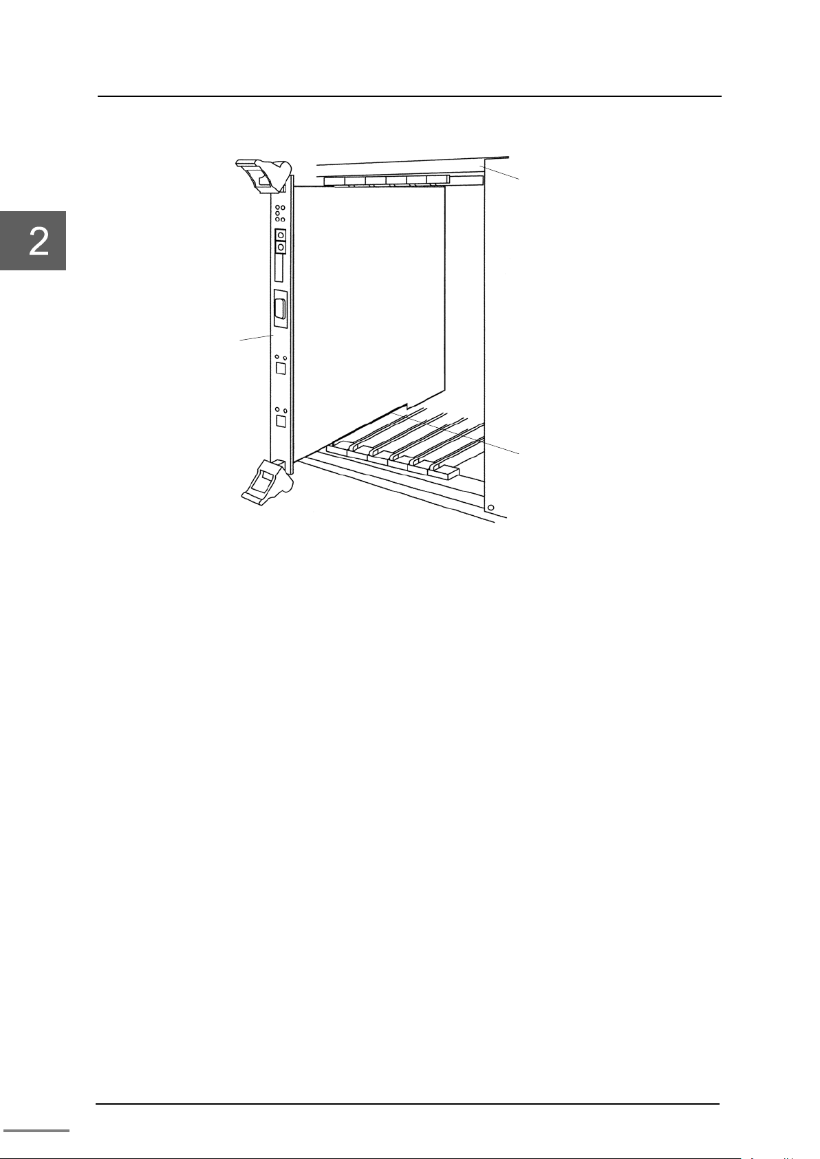
TN8 module
Basic unit
Module guide
of the basic unit
Install the module to the basic unit in the following steps.
As shown in Figure 2-1, insert the module while aligning the
module bottom along the module guide of the basic unit.
The TN8 module can be installed to the following slot numbers.
8-slot basic unit: Slot numbers 2 to 7.
Secure the module.
After installing it to the basic unit, secure it using the screws at the top and
bottom of the module.
Figure 2-1 Installing to the basic unit
Unified Controller nv series TC-net 100 (TN8) Module Operation Manual
Chapter 2 Installation and Wiring
10
Before installation or wiring, remove the static
electricity from your body.
The static electricity accumulated
may cause failure of the product.
Do not touch the cables carelessly.
Applying stress to the cables may cause
malfunction or accidents.
Perform a notification check in the application
level
When an error occurs such as unable to turn on the
power, stop using and contact one of Toshiba's
service representatives.
If you have any question, consult with one of
Toshiba's service representatives.
2.2 Connecting the TC-net 100 Cable
Connect the TC-net 100 cable (optical fiber code) to the TN8 module.
CAUTION
Mandatory
in the human body
CAUTION
Prohibited
CAUTION
Connecting the optical fiber cord (TN821/TN821A, TN822/TN822A)
Connect the optical fiber cord to the MT-RJ type optical connectors
(TN-A and TN-B) as shown below.
using the transmission protocol.
Mandatory
Remove the dust cover of the optical connector.
Remove the dust cover of the optical connector. Pinch the dust cover with
your fingers until it clicks, and then remove it.
Connect the optical fiber cord.
Insert the optical fiber cord into the MT-RJ type connector, and press it in
until it clicks.
Secure the cable.
Secure the cable by clamping it so that no stress is exerted on the cable.
6F8C1360
2.2 Connecting the TC-net100 Cable
11
Allowable bent radius
When
Optical fiber code
5
50
50
Note
The allowable bent radius of the optical fiber cable depends on the product. Follow the
Figure 2-2 Connection of the optical fiber cord
Table 4-1 Allowable bent radius of the cable
fixed
(mm)
When laid
Cable name
Cable outer
diameter (mm)
•
manufacturer's specification of your optical fiber cable.
Unified Controller nv series TC-net 100 (TN8) Module Operation Manual
Chapter 2 Installation and Wiring
12
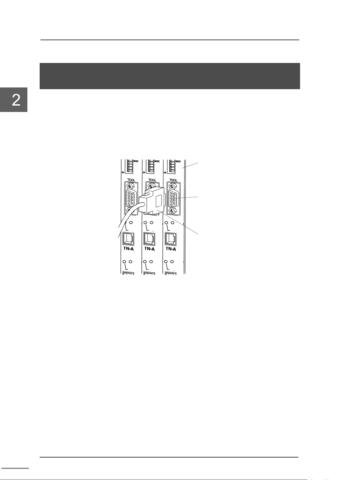
TN8 module
S
(TOOL)
RS-232C cable
ACT-B
LNK-B
ACT-B
LNK-B
ACT-B
LNK-B
ACT-A
LNK-A
ACT-A
LNK-A
ACT-A
LNK-A
2.3 Connecting the Serial Communication Port (RS-232C) Cable
For downloading programs or performing maintenance, the serial
communication port (TOOL) can be used to communicate with the tool.
RS-232C is used for communication.
The RS-232C cable connector is a 9-pin D-sub connector (socket).
erial communication port
Figure 2-3 Connecting the serial communication port
6F8C1360
13
Turn off the basic unit.
When replacing the module, turn off the basic unit
and make sure that the power is off. Otherwise,
failure of the module or electric shock may occur.
2.4 Replacing the Module
CAUTION
When changing the switch settings or in case of failure, replace the
module in the following steps.
Turn off the basic unit.
Make sure that it is off by using LED display.
Unlock the connector lock in the TC-net 100 cable side connected
2.4 Replacing the Module
Mandatory
to the module with your finger, and remove it.
Loosen the screws at the top and bottom of the module with a
Phillips screwdriver, and remove it along the module guide of the
basic unit.
Install the new module to the basic unit, and connect the cables.
Align the switch settings of the new module with that of the
removed unit.
Turn on the power. Use the engineering tool to download the
parameters.
When the download is complete, turn off the basic unit with the
TN8 module implemented again.
Make sure that the basic unit is turned off before wiring the cables.
Unified Controller nv series TC-net 100 (TN8) Module Operation Manual
Chapter 2 Installation and Wiring
14
TN8 module
Basic unit
Module guide
of the basic unit
Figure 2-4 Replacing the TN8 module
6F8C1360

15
Chapter 3 Setting
3.1 Switch Setting ············································· 16
3.1.1 Station address setting switch
(STN-H, STN-L) ···································· 16
3.1.2 Operation mode setting switch (MODE) ······ 17
3.2 Network Parameter Setting ····························· 18
3.2.1 Network ID and subnet mask ·················· 18
3.2.2 Station address ··································· 19
3.2.3 Overview of multicast address ·················· 19
3.3 Setting with the Engineering Tool ···················· 21
3.3.1 Network parameter setting ······················· 22
3.3.2 Setting the scan sending blocks ················ 32
3.3.3 Setting the state change notification ··········· 35
3.4 Network Information ····································· 38
3.4.1 Referring to LAN transmission map ··········· 38
3.4.2 Accessing the scan data ························· 39
3.4.3 Clearing the scan unhealthy state ·············· 39
3.4.4 Clearing the overlapping sending SA ·········· 39
3.4.5 LAN control information ·························· 40
3.4.6 Detailed explanation of LAN management
information ·········································· 41
3.4.7 MIB informat ion ···································· 42
3.4.8 Reception system switching ····················· 43
3.4.9 Viewing the in-ring map ·························· 44
3.5 Option Functions ·········································· 45
3.5.1 Setting the self healthy mode parameters ···· 45
3.6 Setting the RAS Information Block in Scan
Transmission ················································ 47
Chapter 3 Setting
16
•
Set the switches that determine the operation mode and station address of the TN8 module
Name
Description
Setting range : 01 to FE(h)
STN-H
STN-H(upper digit address): 0 to F(h)
STN-L
STN-L(lower digit address): 0 to F(h)
Remark
For setting, use a small slotted screwdriver.
Note
Be careful so that the address does not overlap with other nodes.
3.1 Switch Setting
The switches that determine the operation mode and station address are
on the front panel of the TN8 module.
The method to set the switches is shown below.
Important
before turning the power on.
3.1.1 Station address setting switch (STN-H, STN-L)
The station address setting switches are hexadecimal rotary switches that
determines the station address on the TC-net 100 network.
For setting of the IP address, refer to "3.2 Network parameter setting."
Set the station address (1 to 254) that has been assigned upon system
configuration in a HEX code. Assign an address with a different value to
each of the nodes in the system.
Tab l e 3 -1 shows the setting of a station address.
Table 3-1 Station address setting
(Note) (h) indicates hexadecimal.
•
Set the station address in hexadecimal.
For example, if the address value is 28, it is ‘1C’ (h) when converted to
hexadecimal. Therefore, set as follows:
STN-H side: ‘1’
STN-L side: ‘C’
For decimal-hexadecimal conversion, refer to "Appendix D
Decimal-hexadecimal conversion table."
•
6F8C1360

17
Initial setting
1
SM0
Operation
SM0
off
on
off
SM1
off
off
on
SM2
off
off
off
Operation
Normal
For maintenance
SM0: off
2
SM1
SM1: off
3
SM2
SM2: off
4
RV1
Reserved
Not used
off
5
RV2
Reserved
Not used
off
6
IPF
Reserved
Not used
off
7
IP0
IP address
IP0
off
off
on
on
IP1
off
on
off
on
Operatio
nv series 1
Reserve
nv series 2
Too l
IP0: off
8
IP1
Important
•
Never use the maintenance mode.
3.1.2 Operation mode setting switch (MODE)
The operation mode setting switches are 8-bit dip switches that determine
the operation of the TN8 module.
When the switch lever of each bit of the dip switch is turned to left (to the
ON side), it is set to ON; when it is turned to right, it is set to OFF.
Tab l e 3 -2 shows the descriptions of the switches.
Table 3-2 Operation mode setting table
3.1 Switch Setting
Switch
number
Name Function Setting
mode
type
n
172.16.64.x
x
d
Operation mode
172.31.64.xx
(factory
setting)
(normal
setting)
IP1: off
(nv series 1,
standard)
setting
Normally use the normal setting state.
IP address type
"nv series 1" is the standard.
"nv series 2" is used for expansion. Do not use it normally.
Tool setting is used to use network parameters set by the engineering
tool.
Unified Controller nv series TC-net 100 (TN8) Module Operation Manual

Chapter 3 Setting
18
3.2 Network Parameter Setting
The network parameters can be set with the operation mode setting
switches and station address setting switches.
For methods to set these switches, refer to "Table 3-1 Station address
setting" and "Table 3-2 Operation mode setting table."
For the TN8 module, the following network parameters must be set.
• IP address type
• Station address
Two IP address types are provided; nv series 1 and nv series 2. Also, it can
be set with the engineering tool.
3.2.1 Network ID and subnet mask
nv series 1 setting (Standard setting)
Use the operation mode setting switches to set the IP address type to "nv
series 1."
This is the standard setting of the unified controller system.
Network ID: 172.16.64.XX
(XX indicates the value of the station address setting switches)
Subnet mask : 255.255.192.0
nv series 2 setting
Use the operation mode setting switches to set the IP address type to "nv
series 2."
This setting is used for expansion of the TC-net 100, and not used
normally.
Network ID: 172.31.64.XX
(XX indicates the value of the station address setting switches)
Subnet mask : 255.255.192.0
Arbitrary setting
Use the operation mode setting switches to set the IP address type to
[Tool setting], and set IPF to [ON].
6F8C1360

19
When this setting is selected, it can be set freely from the engineering tool,
No.
Multicast address
1
225.224.0.1
2
225.224.0.2
3
225.224.0.3
4
225.224.0.4
5
225.224.0.5
6
225.224.0.6
7
225.224.0.7
8
225.224.0.8
9
225.224.0.9
10
225.224.0.10
11
225.224.0.11
12
225.224.0.12
and the value has precedence over the value of the station address setting
switches.
However, the following cannot be used in the IP address.
• Addresses starting with 127(7Fh)
• Addresses with all bits of the network address are "0" or "1"
• Addresses with all bits of the host address are "0" or "1"
The value of the subnet mask consists of a series of "1" from the most
significant bit.
3.2.2 Station address
Use the station address setting switches to set the station address.
Any station address can be set; however, it must be unique within the
system. The available setting range for station addresses is from 01(h) to
FE(h)(1 to 254).
3.2 Network Parameter Setting
When the IP address type is [Tool setting], it has precedence over the
value of the station address setting switches. In this case as well, it is
recommended matching the lowermost value of the specified IP address
(5 in the case of 172.16.64.5) and the value of the station address setting
switches. For [Tool setting], set the station address in the dotted decimal
notation using the engineering tool.
3.2.3 Overview of multicast address
The TN8 module supports 15 multicast addresses.
Support addresses are as follows:
Table3-3 Multicast address
Unified Controller nv series TC-net 100 (TN8) Module Operation Manual

Chapter 3 Setting
20
13
225.224.0.13
14
225.224.0.14
15
225.224.0.15
Group A
Controller 1
Controller 2
Controller 4
Controller 5
Controller 6
Controller
3
PC
Group B
Any of the 15 addresses can be selected and registered by using one TN8
module.
Registration to the TN8 module is performed with the engineering tool.
For the registration method, refer to "3.3 Setting with the engineering
tool."
Figure 3-1 An example of multicast group configuration
In multicast, controllers can be grouped as shown in the example of Figure
3-1.
Controllers 1, 2, 4, and 5 belong to Group A, and Controllers 3, 5, and 6
belong to Group B.
In this example, multicast addresses are set as follows:
• Multicast addresses in Group A ……225.224.0.1
• Multicast addresses in Group B ……225.224.0.2
By doing this, the controllers can be grouped by registering them as
follows:
• Controllers 1, 2, 4……225.224.0.1
• Controllers 3, 6…………225.224.0.2
• Controllers 5……………225.224.0.1 and 225.224.0.2
The setting above allows messages to be passed to the controllers that
belong to the group simultaneously.
6F8C1360

21
•
The switch setting becomes effective from the next startup. Restart the controller after
Ethernet
T
N 8 P
N
8
Engineering
Tool(PC)
IP Address:
Subnet
IP Address:
Subnet
3.3 Setting with the Engineering Tool
Settings to the TN8 module can be done with the engineering tool.
For the operation method of the engineering tool, refer to "Unified
Controller nv series/Integrated Controller V series nV-Too l (Basic)
operation manual "(6F8C1290).
Connect the engineering tool and nv series controller via Ethernet.
The Ethernet connection in the nv controller can be made using the
built-in Ethernet of the CPU module or using the TN8 module. The figure
below illustrates how to engineer the configuration using the built-in
Ethernet of the CPU module (Figure 3-2 System configuration of the
setting example).
172.16.64.1
mask: 255.255.192.0
3.4 Network Information
172.16.64.28
mask: 255.255.192.0
Figure 3-2 System configuration of the example
Set the IP address shown in Figure 3-2 to the CPU module. Using the
rotary switch of the CPU module, set the lowermost digit of the IP address
in hexadecimal (in this case, convert "28" into hexadecimal and set
"1C(h)," i.e. H=1,L=C ).
Set the dip switches DSW-5 and DSW-6 of the CPU module to OFF and
OFF, respectively.
For more information on the dip switches of the CPU module, refer to
"Unified Controller nv series Type 1 Function Manual" (6F8C1221) or
"Unified Controller nv series Type 2 Function Manual" (6F8C1362).
Note
setting.
Unified Controller nv series TC-net 100 (TN8) Module Operation Manual

Chapter 3 Setting
22
3.3.1 Network parameter setting
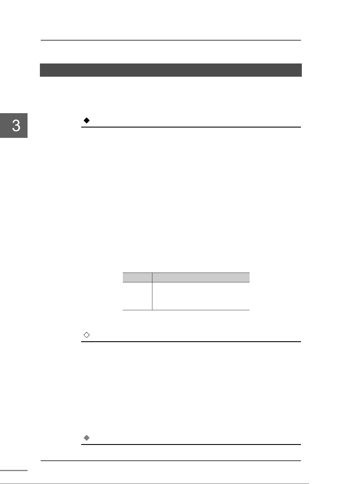
Set the network parameters of the TN8 in the following steps.
Select the TN8 module from the product tree.
Select [Station] under the created system, and select [New (W)] from [File
(F)] on the menu bar.
Figure 3-3 Station registration screen
Set the station name.
Select "nv station" from Station model name, and set the station name
("Stn1" is set in this example).
Figure 3-4 Station name setting screen
6F8C1360
3.4 Network Information
23
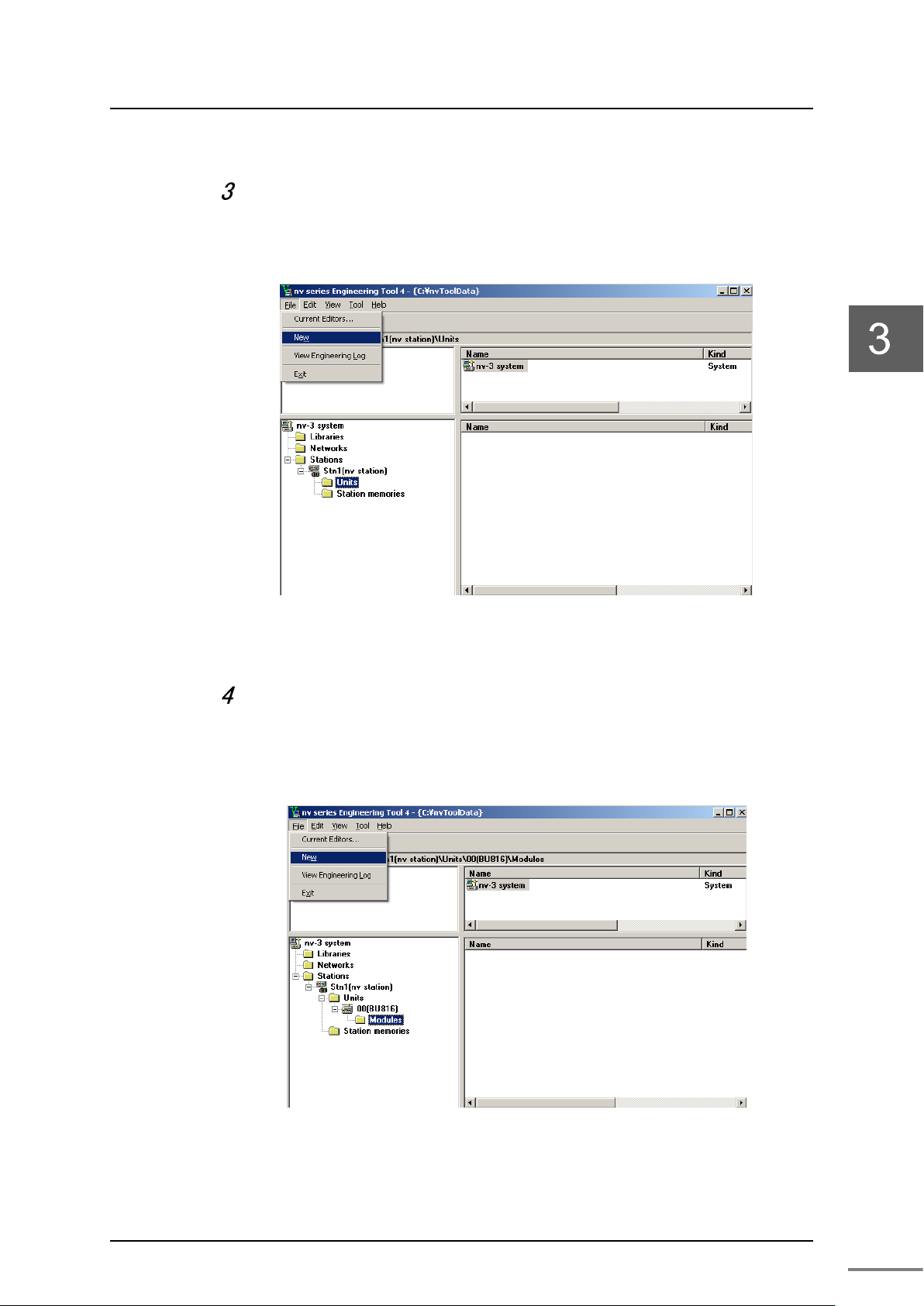
Add the unit to the station.
Select [Unit] under the created station, and select [New (W)] from [File
(F)] on the menu bar.
Figure 3-5 Unit registration screen
Add the module to the unit.
Select [Module] under the unit, and select [New (W)]. Select "TN8 module"
from the module addition dialog.
Figure 3-6 Module registration screen
Unified Controller nv series TC-net 100 (TN8) Module Operation Manual

Chapter 3 Setting
24
Select the added TN8 module.
When [Module parameter] is selected from [File (F)] on the menu bar, the
module parameter screen is displayed.
Figure 3-7 An example of module registration
6F8C1360

3.4 Network Information
25
•
Be careful so that the address does not overlap with other nodes.
When the registration above is complete, check that the network
information of the corresponding TN8 module can be read from the
serial communication port (TOOL).
From the product tree, open the module parameter screen for the TN8
module previously registered.
Figure 3-8 Module parameter registration screen
Register the IP address type, IP address, and subnet mask.
Note
Individual settings are as follows.
· IP address type: Select from V series Standard 1, V series Standard 2,
and Arbitrary.
V series Standard 1 sets all of the operation mode setting switch Bit 7 to
8 of the TN8 module to OFF .
IP address: 172.16.64.xx ("xx" indicates the value of the station address
setting switch.)
Subnet mask: 255.255.192.0
Unified Controller nv series TC-net 100 (TN8) Module Operation Manual

Chapter 3 Setting
26
V series Standard 2 sets the operation mode setting switch Bit 7 of the
TN8 module to ON and the operation mode setting switch Bit 8 to OFF .
IP address : 172.16.64.xx (xx indicates the value of the station address
setting switches)
Subnet mask : 255.255.192.0
The Arbitrary setting sets the operation mode setting switch Bit 7 of the
TN8 module to ON and the dip switch Bit 8 to ON.
In this case, the values set by the tool have precedence in operation over
the value of the station address setting switch.
• Multi-cast registration count: Set a value in the range of 0 to 4. "0"
indicates none is used.
• Multi-cast IP address: Set an address from the 15 addresses from
225.224.0.1 to 225.224.0.15.
To register multi-cast addresses, align them to
the top.
• Scan transmission: Select "Start" online and write to the TN8
module to start or stop scanning from the
engineering tool.
After selecting "Start," the parameter returns
to "Stop" when the TN8 restarts.
• Scan period High: Set a value in the range of 10 to 1600 (the
unit is 0.1ms). "50" indicates 5ms.
• Scan period Medium: Set a value in the range of 2 to 1000 (the unit
is 1ms). "50" indicates 50ms.
• Scan period Low: Set a value in the range of 2 to 10000 (the
unit is 1ms). "500" indicates 500ms.
• Stop scanning when all controllers are down: The default setting is "No."
By default, when a controller is down, the down controller stops the
transmission of only the scan block with the transmission right. The
remaining scan blocks are continued. If "Yes" is selected, when all the
controllers are down, the transmission of the scan blocks of all the
controllers with the transmission right is stopped.
• Reception system selection: Select from Auto Selection/A system
fixed/B system fixed.
• Maximum node distance: Set an integer value for the distance between
the farthest nodes. The default value is 8km.
Using the default value is recommended.
The value can be changed if system
adjustment is required. For example, if the
distance is 7.3km, set "8km."
6F8C1360

3.4 Network Information
27
•
If the controller is in a redundant configuration, the module parameters of the TN8 can be
• Maximum number of repeater stages:
Set a value for the path with the most
repeater stages. The default value is 3.
• Option switch: For the option switches, refer to "3.5 Option
functions."
For Scan period High, Scan period Medium, Scan period Low, Maximum
node distance, and Maximum number of repeater stages, set the same
values for the entire system.
Download the registered information to the TN8 module.
To download, display the parameter information, and click [Download (D)].
Figure 3-9 An example of module parameter registration
Note
downloaded independently by selecting [Primary (P)] and [Secondary (S)] from [Transmission
target].
Restart it.
The downloaded information becomes effective at the next startup.
After the download is complete, restart it.
Unified Controller nv series TC-net 100 (TN8) Module Operation Manual

Chapter 3 Setting
28
From the product tree, set the network.
Select the network under the system, and select [New (W)].
Figure 3-10 Network registration screen
Select [TC-net 1 00LAN] from the network addition dialog.
Select the module under the selected [TC-net 100LAN], and then select
[New (W)].
Figure 3-11 Network addition dialog
6F8C1360

3.4 Network Information
29
Figure 3-12 Network module registration screen
Connect to [TC-net 100LAN].
The TN8 module added previously is displayed on the module addition
dialog. Selecting it connects it to TC-net 100LAN.
Figure 3-13 Network module addition dialog
Unified Controller nv series TC-net 100 (TN8) Module Operation Manual

Chapter 3 Setting
30
Figure 3-14 TC-net 100LAN connection scree n
Connect the engineering tool to the serial communication port
(TOOL) of the TN8 module to obtain the information of the current
TN8 module.
From [Options (O)] in [Hardware Configuration] of the configuration editor,
click [Transmission Parameter (T)] to set the transmission parameter. Use
the serial communication port to confirm it.
Register the following and click [OK].
Transmission method : RS-232C
Port : COM1 (specify the port to use. COM1 in this example)
Timeout time (s): 5
Ethernet timeout time (s): 4
Own station setting: Single
IP Address(172.16.64.1)
6F8C1360

3.4 Network Information
31
Figure 3-15 Transmission parameter setting screen
After the registration is complete, check that the information of the
TN8 module can be read.
Figure 3-16 An example of reading TN8 module information
Unified Controller nv series TC-net 100 (TN8) Module Operation Manual

Chapter 3 Setting
32
3.3.2 Setting the scan sending blocks
Set the scan sending blocks from the product tree.
Select the scan memory of the TC-net 100LAN, and t hen select [Sendin g
Block].
Figure 3-17 Scan sending blocks reading screen
Register each of the blocks.
Register each of the blocks.
Figure 3-18 scan sending blocks setting screen
Block No.: Indicates the scan sending block number.
Word No.: Specify the starting word number used in the block.
Word length: Specify the number of words used in the block.
Transmission speed: Specify the transmission speed of the block in High,
Medium, or Low. The maximum number of items with
each of the transmission speeds are High: 64,
Medium: 128, and Low: 384.
6F8C1360

3.4 Network Information
33
Sending node: Specify the transmission module that sends the block.
Output controller: Specify the controller that uses the block.
Figure 3-19 An example of scan sending blocks registration
Check the setting of the scan sending blocks.
Open the parameter screen of the TN8 module, and select the [Sending
Block] tab.
The transmission speed and information about the slot in which the output
controller using the block are displayed for the registered scan sending
block.
Figure 3-20 Parameter screen of Sending blocks
Unified Controller nv series TC-net 100 (TN8) Module Operation Manual

Chapter 3 Setting
34
Note
If the controller is in a redundant configuration, the module parameters of the TN8 can be
Download the registered data to the TN8.
After checking the data, download it to the TN8 module.
To download, display the parameter information, and select [File
(F)]->[Download (D)].
•
downloaded independently by selecting [Primary (P)] and [Secondary (S)] from [Transmission
target].
Restart it.
The downloaded information becomes effective at the next startup.
After the download is complete, restart it.
Check the registered data.
After the download, display the sending block parameter screen again, and
select [View] -> [Modules] to confirm that the information of TN8 module can
be read.
Figure 3-21 An example of reading TN8 sending blocks information
6F8C1360

35
N8 module
TN8
module.
3.3.3 Setting the state change notification
Set the parameters of state change notification.
Open the parameter screen of the TN8 module, and select the [State
Change Notification] tab.
3.4 Network Information
Figure 3-22 Parameter screen of state change notification
Up to 128 points can be set.
Register "Yes/No" for state change detection. The points with "Yes" are
covered.
In Scan Data Block No., 0 to 2047 blocks are covered.
In Scan Data Word No., 0 to 63 words if the block are covered. The words
are registered in units of 2 words (16 bits x 2), such as 0, 2, 4, …, 58, 60, and
62.
In Scan Data Bit Mask (8 digits in hexadecimal), register which bit in the
word is covered in hexadecimal. Set 0 to the bit to detect it, or 1 not to
detect it.
In Detection Timing, register how the bit changes in order to be detected.
In Notified Controller Slot No., register the slot number (0 to 7) of the
controller that makes a notification when a change occurs in the point.
Note
・Setting register “Yes” for status change detection, “Point No.” is downloaded to T
in the carry. “Point No.” outputted by GET_IFP_INF command becomes “Point No.” from
Unified Controller nv series TC-net 100 (TN8) Module Operation Manual

Chapter 3 Setting
36
Note
If the controller is in a redundant configuration, download the module parameters of the TN8
Download the registered data to the TN8.
After checking the data, download it to the TN8 module.
To downloa d, display the parameter information, and select [File
(F)]->[Download (D)].
•
by selecting [Primary (P)] and [Secondary (S)] from [Transmission Destination].
Restart it.
The downloaded information becomes effective upon the next startup.
After the download is complete, restart it.
Check the registered data.
After the download, display the state change notification parameter screen
again, and select [View] -> [Tools and Modules] to confirm that the
information of TN8 module can be read.
Figure 3-23 An example of reading the state change notification information
According to an example of table 3-23, “point No.2” in [Tool] moves up to “point No.1”
in [Module], because “poi nt No.1” is registe red “No”.
Then, GET_IP_INF command outputs “point No.1”.
6F8C1360
Move up

37
Storage table
GET_IP_INF
information
TC-net
+
+
5
+
8
+9
Storage table in GET_IP_INF command.
Table 3-4 shows storage ta ble det ail .
Table 3-4 Storage table
Status change detection
[W]
Startup factor =1
0
+
State change occurs
1
+
Slot
2
+
Point No.
3
+
Status change
4
Bit history
3.4 Network Information
Remarks
Number of mod ule colum ns of [status chan ge
notification] tab in TN8 module or controller
module.
6
+
Status change
Data
7
+
IP task No.
Unified Controller nv series TC-net 100 (TN8) Module Operation Manual

Chapter 3 Setting
38
3.4 Network Information
3.4.1 Referring to LAN transmission m ap
Display LAN transmission map
In the system view, select the TN8 module, and select [LAN
transmission map (S)] from [Tool (T)] on the menu bar.
Figure 3-24 LAN transmission map selection screen
Display talker state and healthy state
Click “St a rt”
Displayed are the talker state and the healthy state of the current scan
blocks
Figure 3-25 Display screen of the scan talker state and healthy state
6F8C1360

39
3.4.2 Accessing the scan data
To access the scan data, double-click the desired block in the LAN
transmission map screen.
Figure3-26 Display screen of scan data
Select Block No. to access the data of the desired block.
Select Display Format to display the data in decimal or hexadecimal. To
write data to the specific word, double-click the data of the word. Enter
the data to write (make sure that the color changes to red), and select
[Write (W)]. The desired data can be written.
3.4 Network Information
To save the displayed data to a file, click [Save (S)] and specify the file
name.
3.4.3 Clearing the scan unhealthy state
The scan unhealthy map retains the state once the unhealthy state is
detected. Therefore, to confirm the state recovery, clear the scan
unhealthy state.
Click [Stop] on the monitor. Select [Clear Scan Unhealthy] to clear the
scan unhealthy state.
3.4.4 Clearing the overlapping sending S A
If the scan block is sent from multiple nodes redundantly, it is an
overlapping sending state. In the LAN transmission map screen, the
background color of the clock changes to red to indicate the occurrence of
the overlapping state. At the same time, two numbers are displayed in
the block, indicating the node number where the overlapping state exists.
To clear the overlapping state, reset the scan sending block, and
download it to the node with the overlapping state.
After clearing the overlapping state, check that the operation is normal.
The overlapping sending map retains the state once the overlapping
sending state is detected. Therefore, to confirm the state recovery, clear
the overlapping sending SA (station address).
Unified Controller nv series TC-net 100 (TN8) Module Operation Manual

Chapter 3 Setting
40
Click [Stop] on the monitor. Select [Clear Overlapping Sending SA] to
clear the overlapping sending SA (station address).
6F8C1360

41
3.4.5 LAN control information
In the system view, select the TN8 module, and select [LAN management
information (N)] from [Tool (T)] on the menu bar.
3.4 Network Information
Figure 3-27 LAN management information selection screen
Displayed is the information on each node connected to TC-net 100LAN .
Figure 3-28 LAN management information screen
Unified Controller nv series TC-net 100 (TN8) Module Operation Manual

Chapter 3 Setting
42
3.4.6 Detailed ex planation of LAN management inf ormation
When [Detailed explanation (D)] in the LAN management information
screen is clicked, each detailed counter is displayed.
Figure 3-29 Detailed explanation of LAN management information
6F8C1360

43
Remark
MIB: Management Information Base
3.4.7 MIB information
When [MIB information (M)] in the LAN management information screen
is clicked, the details of MIB information are displayed.
•
3.4 Network Information
Figure 3-30 MIB information screen
Unified Controller nv series TC-net 100 (TN8) Module Operation Manual

Chapter 3 Setting
44
3.4.8 Reception system switching
Select Reception system of TC-net 100(Normally receive automatically).
When [Reception switching (X)] in the LAN management information
screen is clicked, the configuration dialog is displayed.
Figure 3-31 TC-net 100 reception switching screen
3.4.9 Viewing the in-ring map
The in-ring map displays the nodes that currently belong to the TC-net
100.
To display the in-ring map, click [In-ring Map (I)] in the LAN
management information screen.
The map is updated to the latest information when [Update (R)] is clicked.
Figure3-32 Display scre en of In-ring map
6F8C1360

45
Note
If the controller is in a redundant configuration, download the module parameters of the TN8
Talker area
When the transmission path
When the transmission path is abnormal
Talker area of
Host controller is normal:
Host controller is normal when
Tal ker area of
Other node is normal:
Always unhealthy
3.5 Option Functions
3.5.1 Setting the self healthy mode parameters
In the self healthy mode, the talker block of the node becomes scan
healthy even if an error occurs in the transmission path. In normal
operation of the TN8 module, all scan blocks become unhealthy if an error
occurs in the transmission path due to disconnection. If the TN8 module
is set to the self healthy mode, the scan healthy information of the talker
block of the node stays in the state when an error occurred in the
transmission path.
To set the TN8 module to the self healthy mode, do the following.
In the parameter screen of the TN8 module, set the option switch to
ON and perform a download.
3.5 Option Functions
•
by selecting [Primary (P)] and [Secondary (S)] from [Transmission Destination].
The following table shows the scan healthy information that is provided by
the TN8 module in the self healthy mode to the host controller.
Table 3-4 Scan healthy information in the self healthy mode
the module
other node
is normal
Healthy
Host controller is abnormal
Unhealthy
Healthy
Other node is abnormal:
Unhealthy
transmission path is abnormal:
Continuously healthy
:
Host controller is abnormal when
transmission path is abnormal:
Continuously unhealthy
(e.g. cable disconnection)
Figure 3-33 shows an example of the self healthy mode configuration.
Unified Controller nv series TC-net 100 (TN8) Module Operation Manual

Chapter 3 Setting
46
Remark
If an error occurs in the host controller after an error occurs in the transmission path, the
PC
JTNI
Cable
E N T N P U E N T N P
U
configuration
(1)
one
)
two
configuration
-unit
(2
-unit
Figure 3-33 An example of the self healthy mode configuration
•
scan block set for the host controller becomes unhealthy.
If the cable is disconnected in one-unit configuration or two-unit configuration, no RAS
•
information other than scan healthy cannot be provided.
6F8C1360

3.6 Setting the RAS Information Block in Scan Transmission
47
•
Do not write to this block from the application.
3.6 Setting the RAS Information Block in Scan Transmission
The RAS information generated by the TN8 module can be expanded in
scan transmission. To register the RAS information generated by the TN8
module in scan blocks for transmission, use the following registration
conditions. For the registration method, refer to "3.3.2 Setting the scan
sending blocks."
RAS information block setting conditions
• BlockNo: 2048 - Station address (the value of the station address
setting switch)
(Example: Block 2043 if the station address is 5)
• CntSlotNo: Slot number (0 to 7) where the TN8 module is installed
• Speed: Medium (M)
If the conditions above are met, the TN8 module generates RAS
information for the scan block for transmission.
The transmission of the RAS information block starts when a scan sending
start request is received from the host controller. After that, the
transmission of the RAS information block continues even if an error
occurs in the host controller.
The scan talker block must be set in the host controller making the scan
sending start request.
Important
Tab l e 3 -5 shows the information configuration of the RAS information
block.
Unified Controller nv series TC-net 100 (TN8) Module Operation Manual

Chapter 3 Setting
48
Word
Update
Install information of the
1
TN8 healthy counter
0.1s 2
Slot 0 healthy counter
0.1s 3
Slot 1 healthy counter
0.1s 4
Slot 2 healthy counter
0.1s 5
Slot 3 healthy counter
0.1s 6
Slot 4 healthy counter
0.1s 7
Slot 5 healthy counter
0.1s 8
Slot 6 healthy counter
0.1s 9
Slot 7 healthy counter
0.1s 10
Reserved - 11
Reserved - 12
Reserved - 13
Reserved - 14
Reserved - 15
Reserved - 16
Controller type
1s
Slot 0 controller
17
Controller subtype
1s 18
Phase/Mode
0.1s 19
Head alarm
0.1s 20
Reserved - 21
Reserved - 22
Controller type
1s
Slot1 controller
23
Controller subtype
1s 24
Phase/Mode
0.1s 25
Head alarm
0.1s 26
Reserved - 27
Reserved - 28
Controller type
1s
Slot2 controller
・
・
・
58
Controller type
1s
Slot7 controller
59
Controller subtype
1s
60
Phase/Mode
0.1s
61
Head alarm
0.1s
62
Reserved -
63
Reserved -
Table 3-5 Inf or m at i on configuration of R AS information block
F 8 7 0
No.
0 Module Type (0x23)
0 0 0 0
cycle
1
0 0
1 1s
target controller(*1)
Remark
・
・
(*1) Install information of the target controller corresponds to 1 - Install, 0 - non-install, 0 bit - 0 slot, 7bits - 7 slots.
6F8C1360
・
・
・
・
For Controller type, controller subtype, phase/mode, head alarm, refer to
the operation manuals of each controller.

49
Chapter 4 Operation
This chapter describes the operations of the TN8 module, such as checking
before operation, startup, and shutdown.

Chapter 4 O perat i on
50
Avoid incorrect setting.
The product does not operate normally if the
switches are set incorrectly. Read this operation
manual thoroughly to avoid incorrect setting.
Stop using immediately when an error occurs.
When an error occurs such as unable to turn on the
power, stop using and contact one of Toshiba's
service representatives.
Note
Checking the switch settings
The switches of the product have been adjusted for the system at the site
adjustment. For normal operation, do not change any switch other than
the ones the customer is required to operate.
CAUTION
CAUTION
Prohibited
Mandatory
Checking before operation
Before turning on the power and operating the product, check again that
the following are as described in this operation manual:
• Switch setting
• Installation
• Wiring
•
Use the engineering tool to check the switch settings (station address setting switch and
operation mode setting switch).
Startup op e r ati on
When the power supply module is turned on, the module starts running
automatically.
When the TN8 module is up and running, check that it is operating
correctly by referring to "Table 1-1 Display details on the state display LED
and normal display" on page 5.
If the module doesn't start up or if the operation is erroneous, stop using
the product immediately and contact one of Toshiba's service
representatives.
Shutdown operation
To s hut down, turn off the power of the power supply module.
6F8C1360

51
Chapter 5 Troubleshooting
This chapter describes troubleshooting for the TN8 module.

Chapter 5 Troubleshooting
52
State name
LED display
LINK-A
ACT-A
Normal
ON -
ON
ON
ON
Blinking
Normal
Switch
Blinking
ON
ON
ON
Blinking
Wrong setting of
Make the setting value
ON -
Blinking
ON
OFF
Wrong setting of
Make the setting value
TC-net 100
Blinking at the
ON
ON
ON
Blinking
TC-net 100
Make them match with
Talker block
Blinking
-
Overlap of talker
Correct the registration
Down
OFF
OFF - - - -
Module error
Contact one of Toshiba's
If the state display LED of the product displays anything different from the
normal display as described in "Table 1-1 Display details on the state
display LED and normal display" on page 5, or if any error is detected in
the human interface station, stop using it immediately and contact one of
Toshiba's service representatives.
To load the RAS data and system log, refer to engineering tool operation
manual.
Fault diagnosis method using the LEDs
Perform diagnosis by referring to the following table.
Table 5-1 Diagnosis using the LEDs
RUN SCAN L-A L-B
operation
setting error
parameter
mismatch
overlap
alternately
same time
-
Loading the RAS data and system log
To load the RAS data and system log, refer to "Unified Controller nv series
/ Integrated Controller V series nV-Tool (Basic) Operation Manual
(6F8C1290)."
alternately
- - -
LINK-B
ACT -B
State Remedy
station address
setting switch
station address
setting switch
parameters do not
match other node
currently in
transmission
blocks is detected
any value other than
(00h) or FF(h).
unique in the system.
the engineering tool.
of the overlapping block.
service representatives
to replace the module.
6F8C1360
When loading fails during serial communication
Load them again. Logs related to serial communication may be traced.
When an error occurs
Load the RAS data and system log before removing the module from the
basic unit.

53
Chapter 6 Maintenance and Inspection
This chapter describes maintenance and inspection such as daily inspection,
periodical inspection, and cleaning of TN 8 module.
6.1 Inspection ···················································· 54
6.1.1 Daily inspection ··································· 54
6.1.2 Periodical inspection ····························· 55
6.2 Life Limited Parts ·········································· 55

Chapter 6 Maint enance and Inspection
54
For safety, avoid touching the interior of the
product.
It may cause an electric shock.
When touching the product for cleaning,
remove the static electricity from your body.
The static electricity accumulat
may cause failure of the product.
When cleaning the product, do not change the
switch setting.
Do not exert any stress on the cables.
Exerting stress on the cables by touching them may
cause malfunction or acc
Stop using immediately when an error occurs.
When an error occurs such as unable to turn on the
power, stop using and contact one of Toshiba's
service representatives.
WARNING
CAUTION
CAUTION
CAUTION
ed in the human body
idents.
Mandatory
Mandatory
Prohibited
Mandatory
6.1 Inspection
6.1.1 Daily inspection
For daily inspection, check the following.
Front p an el
<LED>
Check if each of the LEDs is visible. If not, clean it with a soft cloth. Be
careful not to change the switch settings. Check the LED state from the
front side.
<TC-net 100 connector>
Check the following:
• Cable connection is normal.
• The modular connector is locked.
• Cable connection is not loose or has an abnormal appearance.
If any abnormality is found, contact one of Toshiba's service
representatives.
Ventilation hole
6FE8C1360

6.1 Inspection
55
Check the front panel and upper ventilation hole of the product for dust or
stain. If the ventilation hole is blocked by dust or stain, remove the dust
with a vacuum cleaner, and then wipe it with a soft cloth.
Unified Controller nv series TC-net 100 (TN8) Module Operation Manual

Chapter 6 Maint enance and Inspection
56
Part name
Recommended replacement cycle
Organic semiconductor aluminum
15 years
Electrical double layer capacitors
10 years
Optical module (TN821/TN822 only)
It is recommended measuring output power every
Switches, connectors
A sampling test every 10 years is recommended as
Indoor environment
Check if the temperature and humidity of the location where the product
is located are within the product specification range (Table A-1 in
Appendix A).
6.1.2 Periodical inspection
To prevent accidents and use the product safely for long-term operation,
it is recommended performing a periodical inspection every 6 months.
Also, it is recommended replacing life limited parts regularly (refer to "6.2
Life limited parts"). For a periodical inspection, consult with one of
Toshiba's service representatives.
6.2 Life Limited Parts
To u s e t h e product safely for a long time, replace the life limited parts
regularly. When replacing them, consult with one of Toshiba's service
representatives.
The following table shows the life limited parts and their replacement
cycles.
Table 6-1 Life limited parts and their recommended replacement cycles
solid electrolytic capacitors
10 years.
preventive maintenance.
6FE8C1360

6.2 Life Limited Parts
57
Unified Controller nv series TC-net 100 (TN8) Module Operation Manual

57
Chapter 7 Application Interface
This chapter describes information by socket, transmission path diagnosis
information, TN8 module state information, and usage constraints of the
application interface.
7.1 Information by Socket ·································· 59
7.1.1 Configuration of information by socket ········ 59
7.1.2 Referring to information by socket ············ 60
7.1.3 Timing of generation of information by socket ·· 61
7.2 Transmission Path Diagnosis Information ······· 63
7.2.1 Configuration of the scan data healthy map · 63
7.2.2 Configuration of the scan data unhealthy map · 64
7.2.3 Configuration of the scan data talker map ·· 65
7.2.4 Configuration of RAS information ············· 66
7.2.5 Configuration of in-ring map ··················· 68
7.3 Usage Constraints ······································· 69
7.4 Restriction on Station Redundant Configuration ··· 70

Chapter 7 Application Interface
58
Scan data
Unhealthy map
Scan data
The TN8 module expands the state information by socket used by the user
application as well as diagnosis information of the transmission path to
the TN8 modules within the same network on the station bus. Different is
the address on the station bus expanding each state information.
The configuration of application information on the station bus is as
shown below. For CntBase, refer to”7.1 Information by socket”.
Access from the nv controller
Reserved by the system
Reserved by the system
Information by socket %MW13.CntBase+130944
map %MW13.CntBase+130512
in-ring
Reserved by the system
Healthy map
Scan data
Reserved by the system
Talker map
Reserved by the system
RAS information %MW13.CntBase+344064
Reserved by the system
Scan transmission area %MW13.CntBase+393216
%MW13.CntBase+340608
%MW13.CntBase+340736
%MW13.CntBase+342016
Figure 7-1 Configuration of application information
From the user application of the controller, it is referred to based on the
access from the controller. This notation is by word. The value of
CntBase varies depending on the slot where the TN8 module is installed.
The value of the installation slot will be described later.
The number of sockets that the user can use is as follows.
TN8: 48
6F8C1360

59
Word offset
Socket 0
130944
Socket 1
130945
Socket 2
130946
·
Socket 62
131006
Socket 63
131007
F E D C B A 9 8
TCP
UDP
AOP
POP
CON
RCL
reserve
RCV
7.1 Information by Socket
7.1.1 Conf iguration of information by socket
Figure 7-2 shows the state information by socket.
0
Figure 7-2 State information by socket
Condition that makes each bit "1"
TCP: When socket TCP is used
UDP: When socket UDP is used
AOP: When socket is actively opened (TCP only)
7.1 Information by Socket
POP: When socket is passively opened (TCP only)
CON: While connection is being established (TCP only)
RCV: Received data exists
RCL: Disconnected by the partner when connection is established (TCP
only)
Condition that makes each bit "0"
TCP: Upon close request of the socket
UDP: Upon close request of the socket
AOP: Upon close request of the socket
POP: Upon close request of the socket
CON: Upon close request of the socket
or When connection is disconnected by the partner.
RCV: No received data
RCL: Upon close request of the socket
The following table shows the station bus address where the information
by socket is expanded in word addresses.
Table 7-1 Station bus addresses
Unified Controller nv series TC-net 100 (TN8) Module Operation Manual
·

Chapter 7 Application Interface
60
Beginning of single
Slot 0
0
%MW13.130944
EN_SOCKET_0
Slot 1
1048576
%MW13.1179520
EN_SOCKET_1
Slot 2
2097152
%MW13.2228096
EN_SOCKET_2
Slot 3
3145728
%MW13.3276672
EN_SOCKET_3
Slot 4
4194304
%MW13. 4325248
EN_SOCKET_4
Slot 5
5242880
%MW13. 5373824
EN_SOCKET_5
Slot 6
6291456
%MW13. 6422400
EN_SOCKET_6
Slot 7
7340032
%MW13. 7470976
EN_SOCKET_7
The base address of the station bus address varies depending on the slot
where the TN8 module is installed. The following table shows the
starting word addresses of the information by socket when the TN8
module is installed to different slots.
Table 7-2 Slots and station bus addresses
Base address
(CntBase)
Ethernet information
by socket
7.1.2 Referring to information by socket
As described in "7.1.1 Configuration of information by single Ethernet
socket," information by socket used by each of the user applications is
expanded on the station bus of the TN8 module. There are some
considerations when accessing the information.
When socket communication is performed using an instruction word by
the controller, the socket number is obtained from the instruction word
using the USEND_N command. The socket number is managed by the
controller. The socket number is once converted to a socket ID managed
by the TN8 module. Based on the converted socket ID, the information
by socket is referred to that is expanded on the station bus of the TN8
module.
Symbol name on the
engineering tool
6F8C1360
For detailed explanation of the communication FB, refer to "Unified
Controller nv series/Integrated Controller V series Command Manual"
(6F8C1226).

61
ソケット単位情報
TCP オープン要求
(コマンド:35H、kind=1)
アクティブ(クライアント)
(注:サーバ側は先にオープン要求を行い、
クライアントからの接続要求に備えます)
パッシブ(サーバ)
TCP オープン要求
(コマンド:35H、kind=2)
socket (*1)
<TCP>=1
bind
listen
socket
<TCP>=1
bind
connect
<AOP>=1,<CON>=1
accept
(新しいソケットを生成)
<TCP>=1,<POP>=1,<CON>=1
(注:*1 にて生成したソケットは
命令語にてcloseされます)
TCP 送信要求
(コマンド:37H)
(データ着信)
<RCV>=1
TCP
受信要求
(コマンド:38H)
recv
<RCV>=0
(注:RCV は着信データが有る場
合に ON、無い場合に OFF)
TCP クローズ要求
(コマンド:39H)
shutdown
close
全ビット=0
(リモートクローズ検出
)
<RCL>=1,<CON>=0
TCP クローズ要求
(コマンド:39H)
shutdown
close
全ビット=0
select
(New sock et is generated)
Information by socket
Active (client)
Passive (server)
Note: The server side makes an open
TCP open request
TCP open request
Note: The socket generated at
TCP close request
TCP reception request
TCP transmission
(Command: 37H)
TCP close request
(Remote close detected)
All bits=0
Note: RCV is ON when there
(Data reception)
7.1.3 Timing of generation of inf ormation by socket
The timing of setting and clearing information by socket when opened as
TCP/IP and closed after data transmission is shown below.
request first to prepare for the
connection request from the client.
(Command: 35H, kind=2)
7.1 Information by Socket
(Command: 35H, kind=1)
*1 is closed by the instruc tion
word.
request
(Command: 38H)
is received data and OFF
(Command: 39H)
otherwise.
(Command: 39H)
(Note) When running the controller and then haltin g it, close is requested by the controller basic
software for the socket used by the controller.
Figure 7-3 Information by socket and clear timing (1)
Unified Controller nv series TC-net 100 (TN8) Module Operation Manual

Chapter 7 Application Interface
62
ソケット単位情報
アクティブ
パッシブ
<TCP>
<AOP>
<POP>
<CON>
<RCV>
<RCL>
<TCP>
<AOP>
<POP>
<CON>
<RCV>
<RCL>
オープン
要求
オープン
要求
accept
connect
送信
要求
受信
要求
クローズ
要求
クローズ
要求
Information by socket
Passive
Open
Reception
Close
Open
Reception
Close
Active
The timing of setting and clearing bit information of information by socket
is shown below.
request
request
request
request
request
request
6F8C1360
Figure 7-4 Information by socket and clear timing (2)

7.2 Transmission Path Diagnosis Information
63
F 8 7
0
BL
BL
BL
BL
BL
BL
BL 9 BL 8 BL 7 BL 6 BL 5 BL 4 BL 3 BL 2 BL 1 BL
31
30
29
28
27
26
25
24
23
22
21
20
19
18
17
16
・
2031
2030
2029
2028
2027
2026
2025
2024
2023
2022
2021
2020
2019
2018
2017
2016
BL
BL
BL
BL
BL
BL
BL
BL
BL
BL
BL
BL
BL
BL
BL
BL
7.2 Transmission Path Diagnosis Information
7.2.1 Configuration of the scan data healthy map
The scan data healthy map is managed in the configuration as shown in
Figure 7-5.
The scan data healthy map shows the state information of the
corresponding scan data blocks.
Bit “1” The scan data of the corresponding scan block is
healthy.
Bit “0” Unhealthy
In the scan data healthy map information, the information of the block is
ON when a healthy state of the block is detected, and the information of
the block is OFF when an unhealthy state of the block is detected.
Unhealthy detection condition: An unhealthy state is detected if no scan
data of the block is received within the
diagnosis time determined based on the
scan sending cycle set for the block.
The diagnosis time is set to 500ms if the value four times the scan sending
cycle is less than 500ms. If it is greater than 500ms, the diagnosis time is
set to the value four times the scan sending cycle (rounded up to the
nearest 10ms) (three cycles are diagnosed).
15
14
13
12
11
BL
BL
BL
BL
BL
BL
BL
BL
BL
BL
2047
2046
2045
2044
2043
(Note )BL 25 shows scan block No.25
Figure 7-5 Configuration of Scan healthy map
10
BL
BL
2042
BL
BL
2041
BL
BL
2040
BL
・
BL
2039
0
BL
BL
BL
BL
BL
BL
BL
BL
BL
BL
BL
BL
BL
BL
2038
2037
2036
2035
2034
2033
2032
Unified Controller nv series TC-net 100 (TN8) Module Operation Manual

Chapter 7 Application Interface
64
Note
When clearing the scan unhealthy map to zero, be careful not to clear other areas by
F 8 7
0
BL
BL
BL
BL
BL
BL
BL 9 BL 8 BL 7 BL 6 BL 5 BL 4 BL 3 BL 2 BL 1 BL
BL
BL
BL
BL
BL
BL
BL
BL
BL
BL
BL
BL
BL
BL
BL
BL
・
・
BL
BL
BL
BL
BL
BL
BL
BL
BL
BL
BL
BL
BL
BL
BL
BL
BL
BL
BL
BL
BL
BL
BL
BL
BL
BL
BL
BL
BL
BL
BL
BL
7.2.2 Configuration of the scan data unhealthy map
The scan data healthy map is managed in the configuration as shown in
Figure 7-6.
The scan data healthy map shows the state history information of the
corresponding scan data blocks.
Bit “1” The scan data of the corresponding scan block was
unhealthy before.
Bit “0” not unhealthy before
In the scan data healthy map information, the information of the block is
ON when a healthy state of the block is detected, and the information of
the block is not OFF when an unhealthy state of the block is detected.
Unhealthy detection condition: An unhealthy state is detected if no scan
data of the block is received within the
diagnosis time determined based on the
scan sending cycle set for the block.
15
31
14
30
The diagnosis time is set to 500ms if the value four times the scan sending
cycle is less than 500ms. If it is greater than 500ms, the diagnosis time is
set to the value four times the scan sending cycle (rounded up to the
nearest 10ms) (three cycles are diagnosed).
The scan data unhealthy map indicates whether the block has become
unhealthy one or more times after the scan data unhealthy map is cleared
to zero.
•
mistake.
13
12
11
10
29
28
27
26
25
24
23
22
21
20
19
18
17
・
0
16
2031
2030
2029
2028
2027
2026
2025
2024
2023
2047
2046
2045
2044
2043
2042
2041
2040
2039
(Note) BL 25 shows scan block No.25.
Figure 7-6 Configuration of scan data unhealthy map
6F8C1360
2022
2038
2021
2037
2020
2036
2019
2035
2018
2034
2017
2033
2016
2032

7.2 Transmission Path Diagnosis Information
65
Note
When clearing the scan data talker map to zero, be careful not to clear other areas by
F 8
7 0
Scan block No. 0
Scan block No. 0
Scan block No. 1
Scan block No. 1
Scan block No. 2
Scan block No. 2
・
・
Scan block No. 2046
Scan block No. 2046
Scan block No. 2047
Scan block No. 2047
7.2.3 Configuration of the scan data talker map
The scan data talker map is managed in the configuration as shown in
Figure 7-7.
The scan data talker map displays the lower 8 bits of the sending station
address that is using the corresponding scan data block. Scan Block No.
Sending Station Address contains the address of the sending station using
the scan block.
Scan Block No. Overlapping Source Address contains the address of the
sending station when two or more stations are sending to the scan block.
In the scan data talker map, the address of the sending station is set when
sending to the block is detected. The sending station information
remains set until it is cleared to zero.
The scan data talker map indicates whether the block has detected
sending one or more times after the scan data talker map is cleared to
zero.
•
mistake.
If no sending is detected after the scan data talker map is cleared to zero,
the sending station address and overlapping source address remain zero.
If there is only one station sending to the block, the sending station
address contains the address, and the overlapping source address is zero.
If there are two or more stations sending to the block, the sending station
address and overlapping source address contain the address. In this case,
which station is sending by mistake depends on the user system.
Determine according to the system configuration.
overlapping source address
Overlapping source address
overlapping source address
sending station address
sending station address
sending station address
Overlapping source address
overlapping source address
Figure 7-7 Configuration of the scan data talker map
Unified Controller nv series TC-net 100 (TN8) Module Operation Manual
・
sending station address
sending station address

Chapter 7 Application Interface
66
Word
Update
0
Module type (Note 1)
Reserved
1s
1
Healthy counter
1s 2
Reserved - 3
Reserved -
・
・
63
Reserved -
7.2.4 Configuration of RAS information
In the RAS information area, the information for all nodes is shared. The
state information of each node is updated periodically, which consists of
64 words per node.
The configuration information depends on the node type. The
information of each node is expanded at the position of the station
number x 128 bytes from the beginning of the RAS information area by 64
words.
Figure 7-8 shows the configuration of the information provided by TN8
and JTNI.
No.
(Note 1):Module Type 23H:TN8、4:JTNI
F 8 7 0
・
・
・
・
Figure 7-8 Configuration of RAS information
cycle
Remarks
6F8C1360

7.2 Transmission Path Diagnosis Information
67
Word
Update
Install information of the
1
HUB healthy counter
1s
2
Reserved -
3
Reserved -
4
Optical port 0 Number of received packets (Note 2)
1s
Install Stack 0 (A system)
5
Optical port 1 Number of received packets (Note 2)
1s
6
Optical port 2 Number of received packets (Note 2)
1s
7
Optical port 3 Number of received packets (Note 2)
1s
8
Optical port 4 Number of received packets (Note 2)
1s
9
Optical port 5 Number of received packets (Note 2)
1s
10
Optical port 6 Number of received packets (Note 2)
1s
11
Optical port 7 Number of received packets (Note 2)
1s
12
Electrical Port Number of received packets (Note 2)
1s
13
Reserved -
14
Optical port 0 Number of received packets (Note 2)
1s
Install Stack 0 (B system)
15
Optical port 1 Number of received packets (Note 2)
1s
16
Optical port 2 Number of received packets (Note 2)
1s
17
Optical port 3 Number of received packets (Note 2)
1s
18
Optical port 4 Number of received packets (Note 2)
1s
19
Optical port 5 Number of received packets (Note 2)
1s
20
Optical port 6 Number of received packets (Note 2)
1s
21
Optical port 7 Number of received packets (Note 2)
1s
22
Electrical Port Number of received packets (Note 2)
1s
23
Reserved -
・
・
・
54
Optical port 0 Number of received packets (Note 2)
1s
Install Stack 2 (B system)
55
Optical port 1 Number of received packets (Note 2)
1s
56
Optical port 2 Number of received packets (Note 2)
1s
57
Optical port 3 Number of received packets (Note 2)
1s
58
Optical port 4 Number of received packets (Note 2)
1s
59
Optical port 5 Number of received packets (Note 2)
1s
60
Optical port 6 Number of received packets (Note 2)
1s
61
Optical port 7 Number of received packets (Note 2)
1s
62
Electrical Port Number of received packets (Note 2)
1s
63
Reserved -
Figure 7-9 shows the information configuration HUB provides.
This information is available when A system HUB(UTNH21A/UTLH23A)
operates normally.
No.
F 8 7 0
0 Module Type (0x08) 0 0 0 0 0 0 1 1 60s
Cycle
Remarks
target HUB (Note 1)
・
・
・
・
(Note 1): Bit location is <0>:A0、<1>:B0、<2>:A1、<3>:B1、<4>:A2、<5>:B2
A0 is S t ack 0 of A system HUB。
(Note 2): Number of received packets has number of each port normal packets in 16 bits. It transits in
65535→0→1→2...
Figure 7-9 Configuration of RAS information on HUB
・
・
Unified Controller nv series TC-net 100 (TN8) Module Operation Manual

Chapter 7 Application Interface
68
1F 0
STN
STN
STN
STN
STN
STN
STN
STN
STN
STN
STN
STN
STN
STN
STN
STN
STN
STN
STN
STN
STN
STN
STN
STN
STN
STN
STN
STN
STN
STN
STN
STN
STN
STN
STN
STN
STN
STN
STN
STN
STN
STN
STN
STN
STN
STN
STN
STN
STN
STN
STN
STN
STN
STN
STN
STN
7.2.5 Conf iguration of in-ring map
The in-ring map indicates the state of the stations that belong to the
TC-net 100. The in-ring map shows the stations that are currently on the
network.
If an error occurs in the TC-net 100 network or in the TN8 module itself,
the in-ring map is cleared to zero. The information in the in-ring map is
updated in cycles of 10ms.
Figure 7-10 shows the configuration of the in-ring map.
255
254
253
252
223
222
221
220
63
62
61
60
31
30
29
28
(Note) STN25 shows Station No. 25.
251
219
59
27
250
218
58
26
249
217
57
25
230
229
228
198
197
196
・
・
・
38
37
36
6
5
4
Figure 7-10 Configuration of in-ring map
227
195
35
3
226
194
34
2
225
193
33
1
224
192
32
0
6F8C1360

69
Module
Support
Firmware version
TN821A/TN822A
V01.10 ~
7.3 Usage Constraints
Port number constraints
The TN8 module reserves the following ports.
Port number 10000: PCMP
Use port numbers from 1024 to 65535 other than above.
V er si o n co m bination
The following combination is requi red for TN821A/TN822A.
Table 7-3 TN821A/TN822A Support Version
7.3 Usage Constraints
○
Unified Controller nv series TC-net 100 (TN8) Module Operation Manual

Chapter 7 Application Interface
70
7.4 Restriction on Station Redundant Configuration
If a station redundant configuration is used with the TN8 module, there
are the following restrictions.
Restri ctions on the RAS information block
If a station redundant configuration is used with the TN8 module, do not
register any RAS information block because RAS information generated
by the TN8 module cannot be used.
Therefore, send the information necessary for the application by using a
scan block that is not a RAS information block.
For details on setting the RAS information block, refer to "3.4 Setting the
RAS information block in scan transmission."
6F8C1360

71
Appendix A Specifications
A.1 General Specifications ··································· 72
A.2 TC-net 100 Transmission Specifications ··········· 73
A.3 Function Specifications ·································· 74
A.4 Serial Communication Port (RS-232C) Transmission
Specifications ··············································· 75

Appendix A Specifications
72
Specification
TN821/TN821A/TN822/TN822A
Operating temperature
0 to 55°C
Operating humidity range
10 to 95%RH (no condensation)
Storage temperature range
-
40 to 70°C
Storage humidity range
5 to 95%RH (no condensation)
Power voltage range
4.75 to 5.25VDC (Rating: 5.0VDC)
Current consumption
2.0A or less
Power consumption
10W or less
Allowable outage times
10ms or less
Dust
0.3mg/m3 or less (no conductive dust)
Vibration resistance
5≤f<9: half amplitude 3.5mm
Shock resistance
147m/S2(3-axis directions)
Grounding
Type D grounding (grounding resistance of
Cooling
Natural air cooling or forced air cooling
Module dimensions
262(H)×20(W)×207(D)mm
Weight
500g or less
Communication interface
MT-RJ type optical connectors
Online maintenance
None
A.1 General Specifications
T able A-1 General specifications
Item
range
(product ambient
temperature)
(when rated power is fed)
(when rated power is fed)
(5.0VDC)
9≤f<150: constant acceleration 9.8m/sec2
100Ω or less)
6F8C1360

A.2 TC-net 100 Transmission Specifications
73
Item
Specification
Media access method
DOMA(Deterministic Ordered Multiple Access)
Data transmission speed
100Mbps
Topology
Star
Transmission path
Single bus
Transmission cable/cable
Optical fiber cable:2km
Node count
Up to 254 nodes/system
HUB count
Cascade, 5 stages
Transmission mode
Scan transmission
Scan transmission capacity
128KW/system (16bits/word)
Interface
Optical
Cable
Optical
A.2 TC-net 100 Transmission Specifications
T able A-2 TC-net 100 transmission specifications
method
Redundant bus
・
length
(Total extension is 8km if laser LEDs and optical
fiber single mode are used)
(including optical shared hub UTNH21A)
High-speed cycle:1ms to 160ms
Medium-speed cycle:2ms to 1,000ms
Low-speed cycle:2ms to 10,000ms
Message transmission
TCP/IP system message transmission
2048 blocks/system (64W/block)
Transmission capacity 576 blocks/node
(36KW/node)
(High:64, Medium:128, Low:384)
State change detection
Change detection words 128W/node
Change detection cycle Change detection
words×30μs
Detection signal interval 50ms or more
MT-RJ type optical connector
Quartz GI cable (62.5/125, long wavelength) or
(50/125, long wavelength)
Unified Controller nv series TC-net 100 (TN8) Module Operation Manual

Appendix A Specifications
74
Item
Specification
Protocol
TCP/UDP/IP, PCMP(Note)
Point-to-point transmission
Monitoring function (RAS)
Hardware/software
A.3 Function Specifications
Table A-3 Function specifications
・
Transmission method
(Note) PCMP is Toshiba's protocol.
・
Multicast transmission
・
Broadcast transmission
6F8C1360

A.4 Serial Communication Po rt (RS-232C) Transmission Specifications
75
Item
Specification
Data transmission speed
Max. 56kbps
Synchronization method
Asynchronous
Transmission cable
Cross cable with 9-pin-9-pin D-sub connector
Cable length
Max. 15m
Communication method
Full duplex
Communication setting
Parity bit: None
A.4 Serial Communication Port (RS-232C) Transmission
Specifications
T able A-4 Serial specifications
・
・
Character length: 8 bits
・
Stop bit: 1 bit
Unified Controller nv series TC-net 100 (TN8) Module Operation Manual

Appendix A Specifications
76
6F8C1360

77
Appendix B Outside Dimensions

Appendix B Outside Dimensions
78
TN82
RUN
ERR
L-A
MODE
UN
H
L
STN
TOOL
SCAN
TN-A
LNK-A
ACT-A
160.00mm
約
約
233.35mm
L-B
LNK-B
ACT-B
TN-B
About 262mm
About 2
About
About
Station bus connector
The following figure shows the outside dimensions of the TN8.
2
0mm
35mm
262mm
12mm
Figure B-1 TN8 (TN822/TN822A) outside dimensions
6F8C1360

79
Appendix C Related Products

Appendix C Related Products
80
Product name
Rating
Remark
Optical fiber cord with MT-RJ
9-pin
Table C-1 Related prod ucts
Optical fiber cord
RS-232C cable
optical connector at both
ends
D-sub
Cable in board
Standard length 5m
6F8C1360

81
Appendix D Decimal-hexadecimal Conversion Table

Appendix D Decimal-hexadecimal Conversion Table
82
Decimal
Hexadecimal
Decimal
Hexadecimal
Decimal
Hexadecimal
Decimal
Hexadecimal
0 0 32
20
64
40
96
60 1 1
33
21
65
41
97
61 2 2
34
22
66
42
98
62 3 3
35
23
67
43
99
63 4 4
36
24
68
44
100
64 5 5
37
25
69
45
101
65 6 6
38
26
70
46
102
66 7 7
39
27
71
47
103
67 8 8
40
28
72
48
104
68 9 9
41
29
73
49
105
69
10 A 42
2A
74
4A
106
6A
11 B 43
2B
75
4B
107
6B
12 C 44
2C
76
4C
108
6C
13 D 45
2D
77
4D
109
6D
14 E 46
2E
78
4E
110
6E
15 F 47
2F
79
4F
111
6F
16
10
48
30
80
50
112
70
17
11
49
31
81
51
113
71
18
12
50
32
82
52
114
72
19
13
51
33
83
53
115
73
20
14
52
34
84
54
116
74
21
15
53
35
85
55
117
75
22
16
54
36
86
56
118
76
23
17
55
37
87
57
119
77
24
18
56
38
88
58
120
78
25
19
57
39
89
59
121
79
26
1A
58
3A
90
5A
122
7A
27
1B
59
3B
91
5B
123
7B
28
1C
60
3C
92
5C
124
7C
29
1D
61
3D
93
5D
125
7D
30
1E
62
3E
94
5E
126
7E
31
1F
63
3F
95
5F
127
7F
Table D-1 Decimal-hexadecimal conversion table
6F8C1360

83
Decimal
Hexadecimal
Decimal
Hexadecimal
Decimal
Hexadecimal
Decimal
Hexadecimal
128
80
160
A0
192
C0
224
E0
129
81
161
A1
193
C1
225
E1
130
82
162
A2
194
C2
226
E2
131
83
163
A3
195
C3
227
E3
132
84
164
A4
196
C4
228
E4
133
85
165
A5
197
C5
229
E5
134
86
166
A6
198
C6
230
E6
135
87
167
A7
199
C7
231
E7
136
88
168
A8
200
C8
232
E8
137
89
169
A9
201
C9
233
E9
138
8A
170
AA
202
CA
234
EA
139
8B
171
AB
203
CB
235
EB
140
8C
172
AC
204
CC
236
EC
141
8D
173
AD
205
CD
237
ED
142
8E
174
AE
206
CE
238
EE
143
8F
175
AF
207
CF
239
EF
144
90
176
B0
208
D0
240
F0
145
91
177
B1
209
D1
241
F1
146
92
178
B2
210
D2
242
F2
147
93
179
B3
211
D3
243
F3
148
94
180
B4
212
D4
244
F4
149
95
181
B5
213
D5
245
F5
150
96
182
B6
214
D6
246
F6
151
97
183
B7
215
D7
247
F7
152
98
184
B8
216
D8
248
F8
153
99
185
B9
217
D9
249
F9
154
9A
186
BA
218
DA
250
FA
155
9B
187
BB
219
DB
251
FB
156
9C
188
BC
220
DC
252
FC
157
9D
189
BD
221
DD
253
FD
158
9E
190
BE
222
DE
254
FE
159
9F
191
BF
223
DF
255
FF
Table D-1 Decimal-hexadecimal conversion table
Unified Controller nv series TC-net 100 (TN8) Module Operation Manual

Appendix D Decimal-hexadecimal Conversion Table
84
6F8C1360

Unified Controller nv Series TC-net 100 (TN8) Module Instruction Manual
August
72-34 Horikawa-Cho, Saiwai-Ku, Kawasaki,Japan 212-8585
©
All Right Reserved.
8, 2016 third Edition
Infrastructure Systems & Solutions Company
Industrial Systems Division
Toshiba Corporation 2016 No part of this document may be reproduced
without the prior written consent of Toshiba.
 Loading...