

Page 1
Strata@&. ,
Electronic Key Telephone Systems
.+-
seNIe
INSTALLATION
AND
MAINTENANCE MANUAL ’ -
RELEASE 2
TOSHIBA AMERICA INFDRMATIDN SYSTEMS, INC.
Telecommunication Systems Division
Page 2
Stra
Ekctronic Key Telephone Systems
.*-
semI,
INSTALLATION
AND
MAINTENANCE MANUAL
RELEASE 2
TOSHIBA AMERICA INFORMATION SYSTEMS, INC.
Telecommunication Systems Division
Page 3
I UO~IDW 3 I 3 I CIVI rnnlr i lbt3
ELECTRONlCKEYTELEPHONESYSTElV!S
Strata’ Se a;VI,
TOSHIBA PUBLICATIONS
AUGUST1989
RELEASE 2
GENERAL DESCRIPTION
.
&rat& Se (be
Tech Mist Code: TS-1‘243-fllS
--
E&lease 1
PROGRRM REUDRD FORMS
are located in t-eat- of manual
Page 4

On
somiare
VCCW
the Strata 6e the way to
is kl look at
WE EPROFA
ielI
the dii’ierance between the
chips. The
rekase !
and the reiease 2 is marked VCCU-5.
is
marked
l *-
Page 5
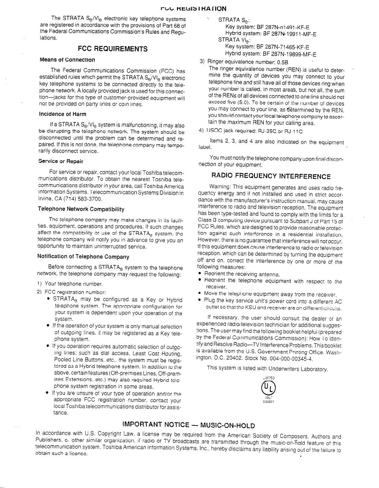
The STRATA Se/Vie electronic key telephone systems
are registered in accordance with the provisions of Part 68 of
the Federal Communications Commission’s Rules and Regulations.
FCC REQUIREMENTS
Means of Connection
The Federal Communications Commission (FCC) has
established rules which permit the STRATA Se/VI, electronic
key telephone systems to be connected directly to the telephone network. A locally provided jack is used for ihis connection-jacks for this type of customer-provided equipment will
not be provided on party iines or coin iines.
Incidence of Harm
If a STRATA Se/Vie system is malfunctioning, it may also
be disrupting the telephone network. The system should be
disconnected until the problem can be determined and repaired. If this is not done, the telephone company may temporarily disconnect service.
Service or Repair
For service or repair. contact your local Toshiba telecom-
munications distributor. To obtain the nearest Toshiba tele-
communications distributor in your area, call Toshiba America
Information Systems. TelecommunicationSystems Division in
Irvine, CA (714) 583-3700.
Telephone Network Compatibility
The telephone company may make changes in its facilities. equipment. operations and procedures. If such changes
affect the compatibility or use of the STRATA, system, the
telephone company will notify you in advance to give you an
opportunity to maintain uninterrupted service,
Notification of Telephone Company
Before connecting a STRATA, system to the telephone
network. the telephone company may request the following:
1) Your telephone number.
2) FCC registration number:
l STRATA, may be configured as a Key or Hybrid
telephone system. The appropriate configuration for
your system is dependent upon your operation of the
system.
l If the operation of your system is only manual selection
of outgoing lines. it may be registered as a Key telephone system.
e If you operation requires automaiic selection of outgo-
ing lines: such as dial access. Least Cost Routing,
Pooled Line Buttons. etc.. the system must be registered as a Hybrid telephone system. In addition to the
above. certain features (Off-premises Lines. Off-premises Extensions. etc.) may also required Hybrid telephone system registration in some areas.
l If you are unsure of your type of operation and/or the
appropriate FCC registration number. contact your
local Toshlbarelecommunications distributor for assis-
tance.
” STRATA Se:
Key system: BF 287N-nl491 -KF-E
Hybrid system: BF 287M19911 -MF-E
STRATA VI,:
Key system: BF 287N-71465KF-E
Hybrid system: BF 287N-19899-MF-E
3) Ringer equivalence number: 0.56
The ringer equivalence number (REN) is useful to deter-
mine the quantity of devices you may connect to your
telephone line and still have all of those devices ring when
your number is called. In most areas, but not all. the sum
of the RENs of all devices connected to one line should not
exceed five (5.0). To be certain of the number of devices
you may connect to your line, as etermined by the REN.
you should contact your local telephone company to ascertain the maximum REN for your calling area.
4) USOC jack required: RJ-25C or RJ-11 C
Items 2, 3, and 4 are also indicated on the equipment
label.
You must notify the telephone company upon final discon-
nection of your equipment.
RADIO FREQUENCY INTERFERENCE
Warning: This equipment generates and uses radio irequency energy and if not installed and used in strict accordance with the manufacturer’s instruction manual. may cause
interference to radio and television reception. The equipment
has been type-tested and found to comply with the limits fo:a
Class B computing device pursuant to Subpart J of Pan
FCC Rules. which are designed to provide reasonable protec-
tion against such interference in a residential installation.
However. there is no guarantee that interference will not occur.
If this equipment does cause interference to radio or television
reception. which can be determined by turning the equipment
off and on. correct the interference by one or more of the
following measures:
l Reorient the receiving antenna.
l Reorient ihe telephone equipment with respect to the
receiver.
l Move the telephone equipment away from the recerver.
l Plug the key service unit’s power cord into a different X
outlet so that the KSU and receiver are on different circu::s.
If necessary. the user should consult the dealer cr an
experienced radio/television technician for additional suggestions. The user may find the following bookiet helpful (prepared
by the Federal Communications Commission): How To Identify and Resolve Radio-TV Interference Problems. This bookiet
is available from the U.S. Government Printing Office. Wash-
ington. D.C. 20402. Stock No. 004-000-00345-4.
This system is listed with Underwriters Laboratory.
,ISTED
ul
0
Xx.
:36601
15
of
IMPORTANT NOTICE - MUSIC-ON-HOLD
In accordance with U.S. Copyright Law, a license may be required from the American Society of Composers. Authors and
Publishers, o. other similar organization. if radio or TV broadcasts are transmitted through the music-on-field feature of this
?elecommunrcation system. Toshiba American Information Systems, Inc.. hereby disclaims any
obtain such a license.
liability arising
out of the failure :o
Page 6
TOSHIBA SYSTEM PRACTICES
’ ELECTRONIC KEY TELEPHONE SYSTEMS
TABLE OF CONTENTS
STRATA Se/VI,
GENERAL DESCRIPTION
- AUGUST 1989
PARAGRAPH
1
2
5
6
7
SUBJECT PAGE
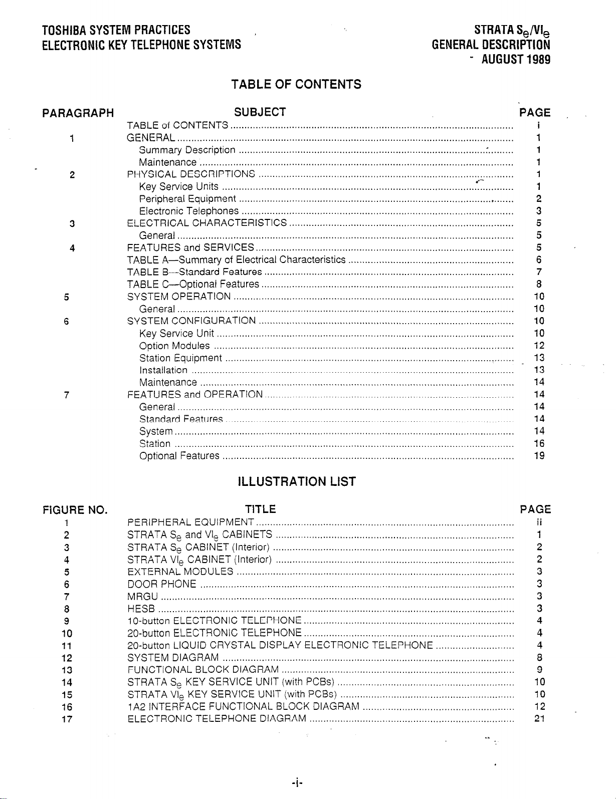
TABLE of CONTENTS .....................................................................................................
GENERAL ........................................................................................................................
Summary Description ....................................................................................... .:. ........
Maintenance ................................................................................................................
PHYSICAL DESCRIPTIONS ...........................................................................................
Key Service Units :I.......... ...........................................................................................
Peripheral Equipment .......................................................................................... . .......
Electronic Telephones .................................................................................................
ELECTRICAL CHARACTERISTICS ................................................................................
General ........................................................................................................................
FEATURES and SERVICES.. ..........................................................................................
TABLE A-Summary of Electrical Characteristics ...........................................................
TABLE B-Standard Features .........................................................................................
TABLE C-Optional Features ..........................................................................................
SYSTEM OPERATION ....................................................................................................
General ........................................................................................................................
SYSTEM CONFIGURATION ...........................................................................................
Key Service Unit ..........................................................................................................
Option Modules ...........................................................................................................
Station Equipment .......................................................................................................
Installation ...................................................................................................................
Maintenance ................................................................................................................
FEATURES and OPERATION .........................................................................................
General ........................................................................................................................
Standard Features .......................................................................................................
System
Station .........................................................................................................................
Optional Features ........................................................................................................
.........................................................................................................................
i
1
1
1
1
1
2
3
5
5
5
6
7
8
IO
10
10
10
i2
13
13
14
14
14
14
14
16
19
FiGURE NO.
1
2
3
4
5
6
7
8
9
10
11
12
13
14
15
16
17
ILLUSTRATION LIST
TlTLE PAGE
PERIPHERAL EQUIPMENT.. ..........................................................................................
STRATA Se and VI, CABINETS .....................................................................................
STRATA Se CABINET (Interior) ......................................................................................
STRATA Vie CABINET (Interior) .....................................................................................
EXTERNAL MODULES ...................................................................................................
DOOR PHONE ................................................................................................................
MRGU ..............................................................................................................................
HESB ...............................................................................................................................
1 O-button ELECTRONIC TELEPHONE ...........................................................................
20-button ELECTRONIC TELEPHONE ...........................................................................
20-button LIQUID CRYSTAL DISPLAY ELECTRONIC TELEPHONE ............................
SYSTEM DIAGRAM ........................................................................................................
FUNCTIONAL BLOCK DIAGRAM ...................................................................................
STRATA Se KEY SERVICE
STRATA Vie KEY SERVICE UNIT (with PC&) ..............................................................
lA2 INTERFACE FUNCTIONAL
ELECTRONIC TELEPHONE DIAGRAM .........................................................................
UNIT (with PCBs)
BLOCK DIAGRAM
...............................................................
......................................................
-3
:
ii
1
2
2
3
3
3
3
4
4
4
8
9
10
10
12
21
Page 7
STRATA Se/VI,
GENERAL DESCRIPTION
AUGUST 1989
REMOTE
MAINTENANCE
STANDARD
TELEPHONE
DOOR LOCK/ALARM
m
PRINTER
EXTERNAL
SPEAKER
K--Y-i
ELECTRONIC
TELEPHONE
OFF-HOOK
CALL ANNOUNCE -
CENTREX
DOoR PHONE/
MONITOR STATION
LEAST
COST
ROUTING
LCD
ELECTRONIC
TELEPHONE
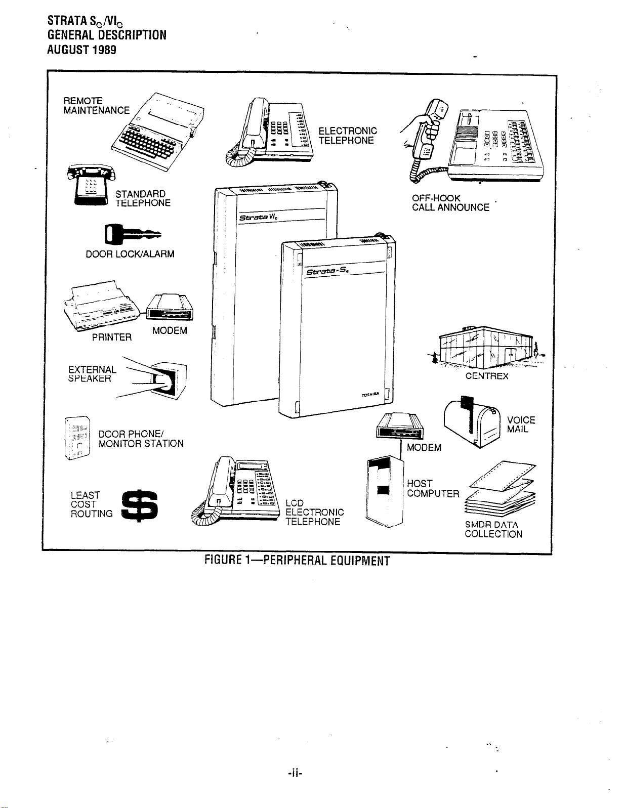
FIGURE%PERIPHERALEQUIPMENT
SMDR DATA
COLLECTION
Page 8
STRATAS,/VI,
GENERAL DESCRIPTION
- AUGUST 1989
1 GENERAL
Summary Description
STRATA Se and VI, are advanced electronic
key telephone systems designed to function in a
variety of situations. Both systems are electrically
- compatible with the public telephone network and
can also be applied in a”behind” PBX. CENTREX.
or IA2 environment.
Figure 1 shows all the basic electronic key
system features, including CENTREX (CTX) capabilities and the impressive package of optional
features provided by these two systems. These
features offer, among others, enhanced connectiv-
ity with stand-alone voice mail products, off-hook
call announce (OCA), SMDR, remote administration/maintenance, and 32-character alphanumeric
Liquid Crystal Display read-outs. Wherever a CO
line interface is indicated in the following text, it can
be a COiCTX and/or PBX line.
Very similar in design, both systems are based
on stored-program control, custom LSI circuitry,
solid-state. space-division switching and reduced
station cabling, and are housed in single cabinets.
locating and replacing defective plug-in units.
keeping service disruption to a minimum. In addition, remote administration/maintenance is also an
available option for both systems.
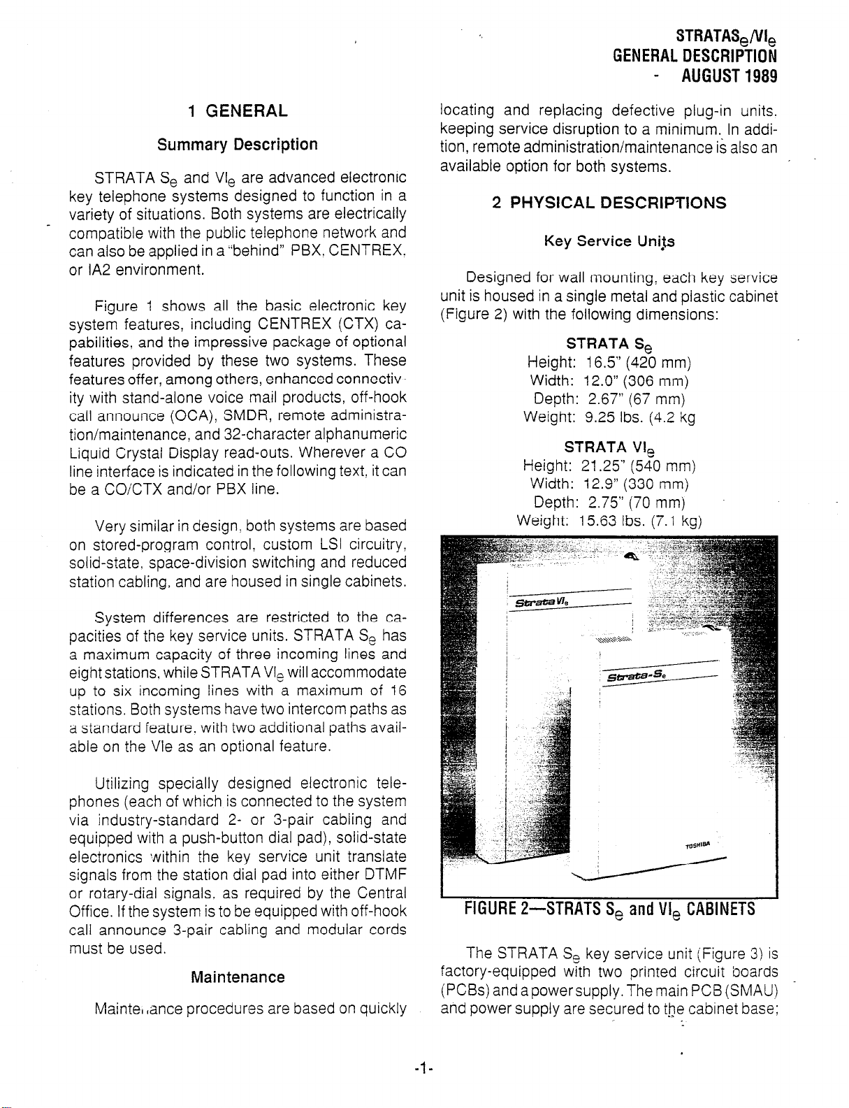
2 PHYSICAL DESCRIPTIONS
Key Service Uni+Js
Designed for wall mounting, each key service
unit is housed in a single metal and plastic cabinet
(Figure 2) with the following dimensions:
STRATA Se
Height: 16.5” (420 mm)
Width: 12.0” (306 mm)
Depth: 2.67” (67 mm)
Weight: 9.25 Ibs. (4.2 kg
STRATA VI,
Height: 21.25” (540 mm)
Width: 12.9” (330 mm)
Depth: 2.75” (70 mmj
Weight: 15.63 Ibs. (7.1 kg)
System differences are restricted to the capacities of the key service units. STRATA Se has
a maximum capacity of three incoming lines and
eight stations, while STRATA VI, will accommodate
up to six incoming lines with a maximum of 16
stations. Both systems have two intercom paths as
a standard feature. with two additional paths available on the Vle as an optional feature.
Utilizing specially designed electronic telephones (each of which is connected to the system
via industry-standard 2- or 3-pair cabling and
equipped with a push-button dial pad), solid-state
electronics within the key service unit translate
signals from the station dial pad into either DTMF
or rotary-dial signals. as required by the Central
Office. If the system is to be equipped with off-hook
call announce 3-pair cabling and modular cords
must be used.
Maintenance
Maintel ,ance procedures are based on quickly
FIGURE 2-STRATS S, and VI, CABINETS
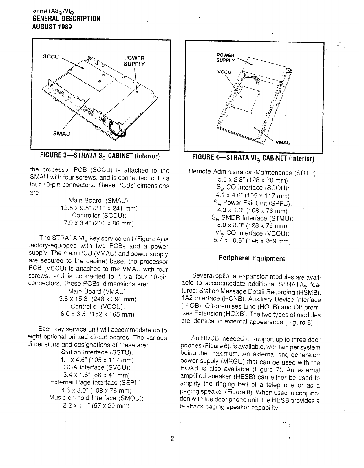
The STRATA Se key service unit (Figure 3) is
factory-equipped with two printed circuit boards
(PCBs) and a power supply. The main PCB (SMAU)
and power supply are secured to the cabinet base;
-l-
Page 9
3 I nn I Hc5g/l~
GENERAL DESCRIPTION
AUGUST 1989
FIGURE 3-STRATA S, CABINET (Interior)
the processor PCB (SCCU) is attached to the
SMAU with four screws, and is connected to it via
four 1 O-pin connectors. These PCBs’ dimensions
are:
Main Board (SMAU):
12.5 x 9.5” (318 x 241 mm)
Controller (SCCU):
7.9 x 3.4” (201 x 86 mm)
The STRATA Vie key service unit (Figure 4) is
factory-equipped with two PCBs and a power
supply. The main PCB (VMAU) and power supply
are secured to the cabinet base; the processor
PCB (VCCU) is attached to the VMAU with four
screws, and is connected to it via four IO-pin
connectors. These PCBs’ dimensions are:
Main Board (VMAU):
9.8 x 15.3” (248 x 390 mm)
Controller (VCCU):
6.0 x 6.5” (152 x 165 mm)
Each key service unit will accommodate up to
eight optional printed circuit boards. The various
dimensions and designations of these are:
Station Interface (SSTU):
4.1 x 4.6” (105 x 117 mm)
OCA Interface (SVCU):
3.4 x 1.6” (86 x 41 mm)
External Page Interface (SEPU):
4.3 x 3.0!’ (108 x 76 mm)
Music-on-hold Interface (SMOU):
2.2 x 1 .l” (57 x 29 mm)
FIGURE 4-STRATA VI, CABINET (Interior)
Remote Administration/Maintenance (SDTU):
5.0 x 2.8” (128 x 70 mm)
Se CO Interface (SCOU):
4.1 x 4.6” (105 x 117 mm)
Se Power Fail Unit (SPFU):
4.3 x 3.0” (108 x 76 mm)
Se SMDR Interface (STMU):
5.0 x 3.0” (128 x 76 mm)
VI, CO Interface (VCOU):
5.7 x 10.6” (146 x 269 mm)
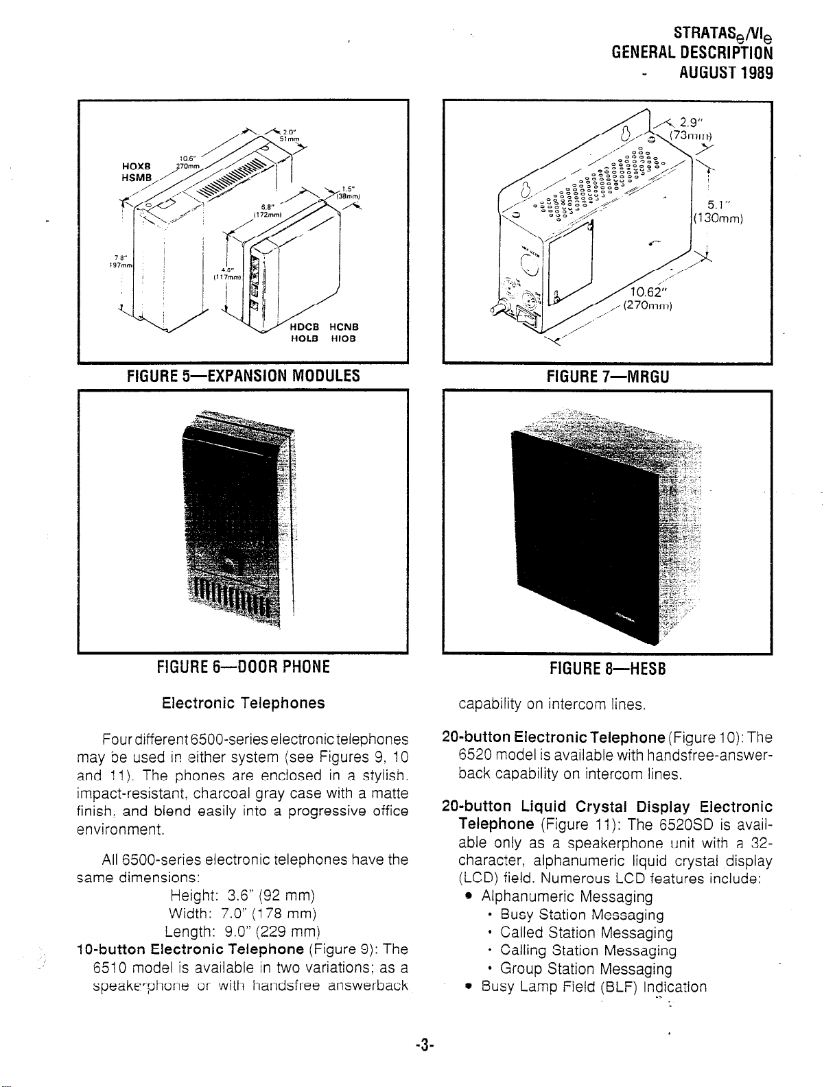
Peripheral Equipment
Several optional expansion modules are available to accommodate additional STRATA, features: Station Message Detail Recording (HSMB),
IA2 Interface (HCNB), Auxiliary Device Interface
(HIOB), Off-premises Line (HOLB) and Off-premises Extension (HOXB). The two types of modules
are identical in external appearance (Figure 5).
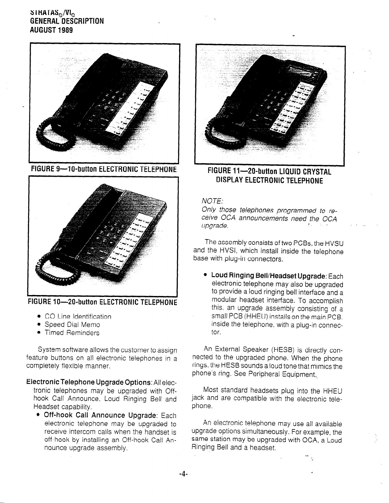
An HDCB. needed to support up to three door
phones (Figure 6), is available, with two per system
being the maximum. An external ring generator/
power supply (MRGU) that can be used with the
HOXB is also available (Figure 7). An external
amplified speaker (HESB) can either be used to
amplify the ringing bell of a telephone or as a
paging speaker (Figure 8). When used in conjunc-
tion with the door phone unit, the HESB provides a
talkback paging speaker capability.
-2-
. .
.
Page 10
STRATAS,/VI,
GENERALDESCRIPTION
AUGUST1989
(130mm)
k’
FIGURE%EXPANSION MODULES
FiGUREbOOORPHONE
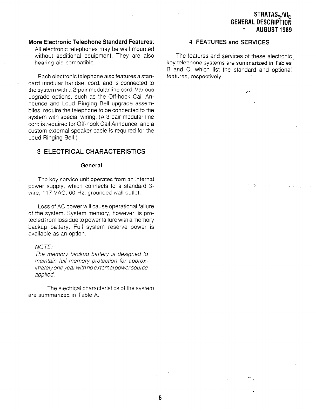
Electronic Telephones
Four different 6.500-series electronic telephones
may be used in either system (see Figures 9, 10
and 11). The phones are enclosed in a stylish.
impact-resistant, charcoal gray case with a matte
finish, and blend easily into a progressive office
environment.
All &ZOO-series electronic telephones have the
same dimensions:
Height: 3.6” (92 mm)
Width: 7.0” (I 78 mm)
Length: 9.0” (229 mm)
1 O-button Electronic Telephone
6510 model is available in two variations: as a
speakerphone or with handsfree answerback
(Figure 9): The
FIGURE'/-MRGU
FlGURE8--HESB
capability on intercom lines.
20-button Electronic Telephone
(Figure 10): The
6520 model is available with handsfree-answerback capability on intercom lines.
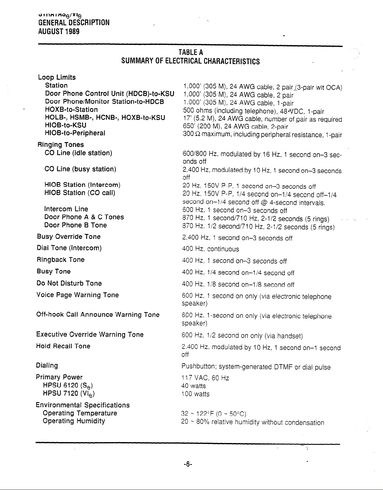
20-button Liquid Crystal Display Electronic
Telephone
able only as a speakerphone unit with a 32character, alphanumeric liquid crystal display
(LCD) field. Numerous LCD features include:
@ Alphanumeric Messaging
l
l
l
l
e Busy Lamp Field (BLF) Indication
(Figure 11): The 6520SD is avail-
Busy Station Messaging
Called Station Messaging
Calling Station Messaging
Group Station Messaging
.3
:
-3-
Page 11
3 I HATAS,/&
GENERAL DESCRIPTION
AUGUST 1989
FIGURE 9-W-button ELECTRONIC TELEPHONE
FIGURE Xl-ZO-button ELECTRONIC TELEPHONE
0 CO Line Identification
l
Speed Dial Memo
l
Timed Reminders
System software allows the customer to assign
feature buttons on all electronic telephones in a
completely flexible manner.
Electronic Telephone Upgrade Options:
tronic telephones may be upgraded with Offhook Call Announce. Loud Ringing Bell and
Headset capability.
l
Off-hook Call Announce Upgrade:
electronic telephone may be upgraded to
receive intercom calls when the handset is
off-hook by installing an Off-hook Call Announce upgrade assembly.
All elec-
Each
FIGURE 1 I-20-button LIQUID CRYSTAL
DISPLAY ELECTRONIC TELEPHONE
NOTE:
On/y those telephones programmed to receive OCA announcements need the OCA
upgrade.
The assembly consists of two PCBs, the HVSU
and the HVSI, which install inside the telephone
base with plug-in connectors.
l
Loud Ringing Bell/Headset Upgrade:
electronic telephone may also be upgraded
to provide a loud ringing bell interface and a
modular headset interface. To accomplish
this. an upgrade assembly consisting of a
small PCB (HHEU) installs on the main PCB.
inside the telephone. with a plug-in connector.
An External Speaker (HESB) is directly connected to the upgraded phone. When the phone
rings, the HESB sounds a loud tone that mimics the
phone’s ring. See Peripheral Equipment.*
Most standard headsets plug into the HHEU
jack and are compatible with the electronic tele-
phone.
An electronic telephone may use all available
upgrade options simultaneously. For example, the
same station may be upgraded with OCA, a Loud
Ringing Bell and a headset.
.s
4
Each
--
-4-
Page 12
STRATAS,/VI,
GENERAL DESCRIPTION
AUGUST1989
More Electronic Telephone Standard Features:
All electronic telephones may be wall mounted
without additional equipment. They are also
hearing aid-compatible.
Each electronic telephone also features a standard modular handset cord, and is connected to
the system with a 2-pair modular line cord. Various
upgrade options, such as the Off-hook Call Announce and Loud Ringing Bell upgrade assemblies, require the telephone to be connected to the
system with special wiring. (A 3-pair modular line
cord is required for Off-hook Call Announce, and a
custom external speaker cable is required for the
Loud Ringing Bell.)
3 ELECTRICAL CHARACTERISTICS
General
The key service unit operates from an internal
power supply: which connects to a standard 3wire.
117
VAC. 60-Hz. grounded wall outlet.
4 FEATURES and SERVICES
The features and services of these electronic
key telephone systems are summarized in Tables’
B and C, which list the standard and optional
features, respectively.
Loss of AC power will cause operational failure
of the system. System memory, however. is pro-
tected from loss due to power failure with a memory
backup battery. ‘Full system reserve power is
available as an option.
NOTE:
The memory backup battery is designed to
maintain full memory protection for approximatelyone year with no externalpowersource
applied.
The electrical characteristics of the system
are summarized in Table A.
-5-
Page 13
alnHlAJe/Vle
GENERALDESCRIPTION
AUGUST1989
SUMMARYOFELECTRICALCHARACTERISTICS
Loop Limits
Station
Door Phone Control Unit (HDCB)-to-KSU
Door Phone/Monitor Station-to-HDCB
HOXB-to-Station
HOLB-, HSMB-, HCNB-, HOXB-to-KSU
HIOB-to-KSU
HIOB-to-Peripheral
Ringing Tones
CO Line (idle station)
CC Line (busy station)
HIOB Station (Intercom)
HIOB Station (CO call)
Intercom Line
Door Phone A & C Tones
Door Phone B Tone
TABLEA
1,000’ (305 M), 24 AWG cable, 2 pair,(3-pair wit OCA)
1,000’ (305 M), 24 AWG cable, 2 pair
1 .OOO’ (305 M), 24 AWG cable, 1 -pair
500 ohms (including telephone), 48*VDC, l-pair
17’ (5.2 M), 24 AWG cable, number of pair as required
650’ (200 M), 24 AWG cable, 2-pair
300 R maximum, including peripheral resistance, 1 -pair
600/800 Hz. modulated by 16 Hz, 1 second on-3 seconds off
2.400 Hz, modulated by 10 Hz! 1 second on-3 seconds
off
20 Hz! 15OV P-P: 1 second on-3 seconds off
20 Hz, 15OV P-P, l/4 second on-l/4 second off-l/4
second on-l/4 second off @ 4-second intervals.
600 Hz, 1 second on-3 seconds off
870 Hz: 1 second/710 Hz, 2-l/2 seconds (5 rings)
870 Hz. l/2 second/710 Hz, 2-l/2 seconds (5 rings)
Busy Override Tone
Dial Tone (intercom)
Ringback Tone
Busy Tone
Do Not Disturb Tone
Voice Page Warning Tone
Off-hook Call Announce Warning Tone
Executive Override Warning Tone
Hold Recall Tone
Dialing
Primary Power
HPSU 6120 (Se)
HPSU 7120 (VI,)
Environmental Specifications
Operating Temperature
Operating Humidity
2.400 Hz, 1 second on-3 seconds off
400 Hz, continuous
400 Hz? 1 second on-3 seconds off
400 Hz, i/4 second on-l/4 second off
400 Hz, l/8 second on-l 18 second off
600 Hz. 1 second on only (via electronic telephone
speaker)
600 Hz. 1 -second on only (via electronic telephone
speaker)
600 Hz. 112 second on only (via handset)
2.400 Hz. modulated by IO Hz, 1 second on-l second
off
Pushbutton; system-generated DTMF or dial pulse
117VAC; 60Hz
40 watts
100 watts
32 - 122"F(O
20 m 80% relative humidity without condensation
..,
50°C)
Page 14
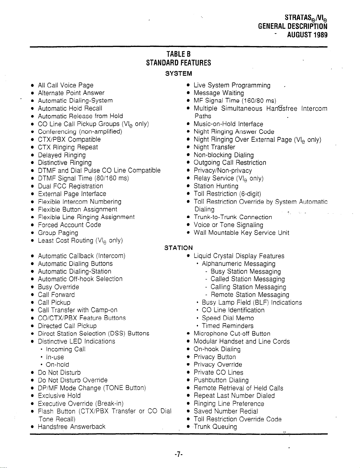
TABLEB
STANDARDFEATURES
SYSTEM
l
All Call Voice Page
l
Alternate Point Answer
o Automatic Dialing-System
l
Automatic Hold Recall
l
Automatic Release from Hold
l
CO Line Call Pickup Groups (Vie only)
e Conferencing (non-amplified)
l
CTXiPBX Compatible
l
CTX Ringing Repeat
l
Delayed Ringing
l
Distinctive Ringing
l
DTMF and Dial Pulse CO Line Compatible
l
DTMF Signal Time (80/160 ms)
0 Dual FCC Registration
l
External Page Interface
l
Flexible Intercom Numbering
l
Flexible Button Assignment
0 Flexible Line Ringing Assignment
l
Forced Account Code
0 Group Paging
9 Least Cost Routing (VI, only)
STATION
l
Automatic Callback (Intercom)
@ Automatic Dialing Buttons
s Automatic Dialing-Station
s Automatic Off-hook Selection
* Busy Override
l
Call Forward
@ Call Pickup
* Call Transfer with Camp-on
* COICTXIPBX Feature Buttons
l
Directed Call Pickup
9 Direct Station Selection (DSS) Buttons
s Distinctive LED Indications
l
Incoming Call
l
In-use
l
On-hold
0 Do Not Disturb
s Do Not Disturb Override
0 DP’MF Mode Change (TONE Button)
0 Exclusive Hold
* Executive Override (Break-in)
e Flash Button (CTXIPBX Transfer or CO Dial
Tone Recall)
l
Handsfree Answerback
STRATAS,/VI,
GENERALDESCRIPTION
AUGUST1989
l
Live System Programming .
l
Message Waiting
l
MF Signal Time (160/80 ms)
l
Multiple Simultaneous Han&free Intercom
Paths
l
Music-on-Hold Interface
l
Night Ringing Answer Code
l
Night Ringing Over External Page (Vie only)
* Night Transfer
* Non-blocking Dialing
l
Outgoing Call Restriction
@ Privacy/Non-privacy
* Relay Service (VI, only)
l
Station Hunting
0 Toll Restriction (6-digit)
l
Toll Restriction Override by System Automatic
Dialing
l
Trunk-to-Trunk Connection
e Voice or Tone Signaling
* Wall Mountable Key Service Unit
s Liquid Crystal Display Features
l
Alphanumeric Messaging
- Busy Station Messaging
- Called Station Messaging
- Calling Station Messaging
- Remote Station Messaging
l
Busy Lamp Field (BLF) Indications
l
CO Line Identification
l
Speed Dial Memo
l
Timed Reminders
0 Microphone Cut-off Button
l
Modular Handset and Line Cords
l
On-hook Dialing
* Privacy Button
l
Privacy Override
* Private CO Lines
0 Pushbutton Dialing
l
Remote Retrieval of Held Calls
* Repeat Last Number Dialed
l
Ringing Line Preference
l
Saved Number Redial
l
Toll Restriction Override Code
l
,Trunk Queuing
d ._
-7-
Page 15
STRATASJVI,
GENERALDESCRIPTION
AUGUST1989
l
lA2 Key System Interface (HCNB)
0 Amplified Conference
l
Auxiliary Device Interface (HIOB)
l
Call Forward to Voice Mailbox
l
Message Waiting Indication
l
Voice Mail Control
l
Background Music with Station Control
l
Door Phone/Monitor Station
l
Alarm Button
l
Door Lock Button
l
Electronic Telephones
l
1 O-button Handsfree Answerback or speak-
erphone
l
20-button Handsfree Answerback
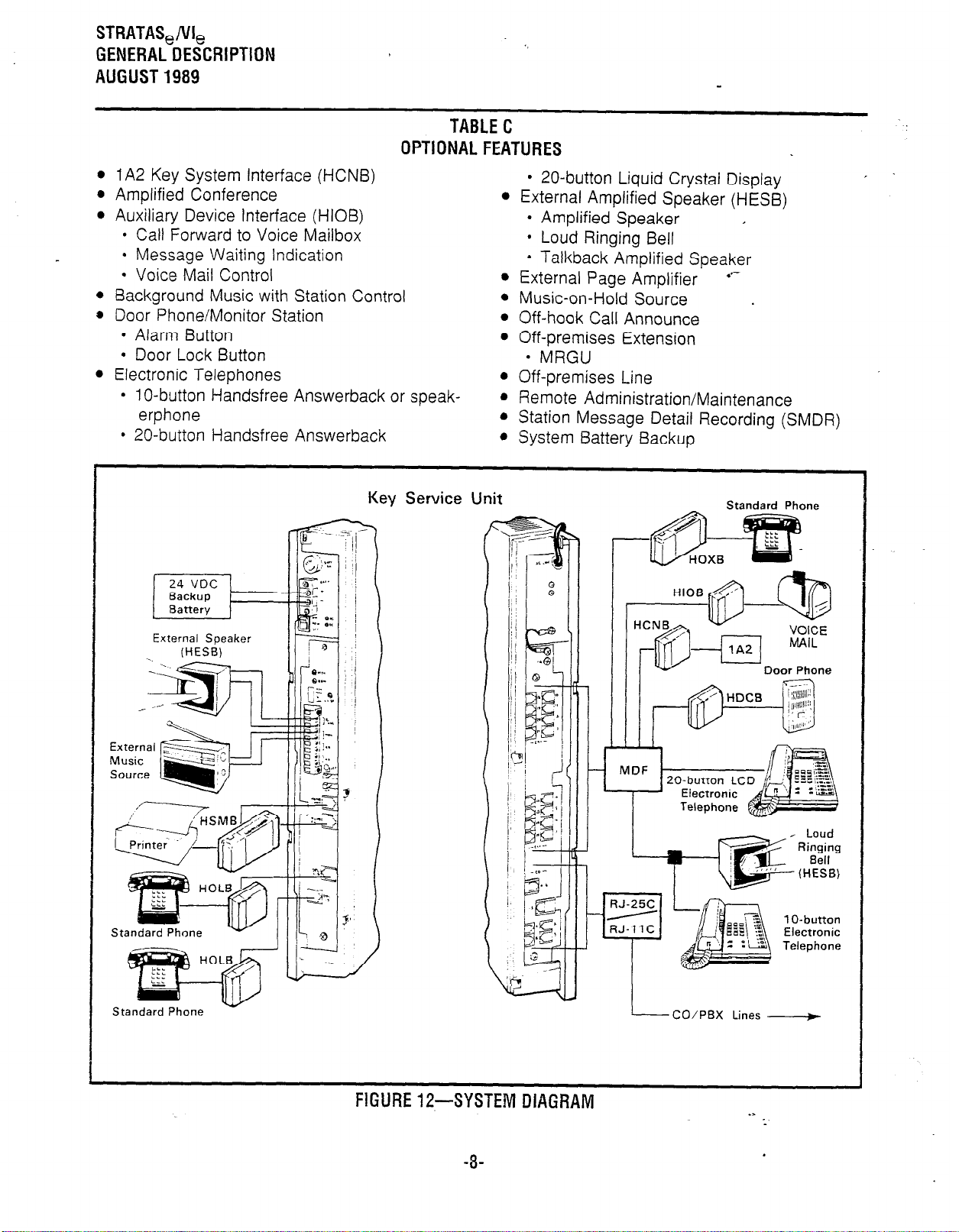
TABLEC
OPTIONALFEATURES
l
20-button Liquid Crystal Display
l
External Amplified Speaker (HE%)
l
Amplified Speaker
l
Loud Ringing Bell
* Talkback Amplified Speaker
l
External Page Amplifier
l
Music-on-Hold Source
l
Off-hook Call Announce
l
Off-premises Extension
l
MRGU
l
Off-premises Line
. Remote Administration/Maintenance
l
Station Message Detail Recording (SMDR)
l
System Battery Backup
,
,
.*-
External
Music
Source
24 VDC
Backup
Battery
External Speaker
Service 1 Jnit
Key
Standard Phone
lT!@sk
1 O-huttnr
Electronic
Telephone
FlGURE12-SYairtlvl
-8-
UlALiHAM
L-_CO/PBX Lines ___f
.>
Page 16
STRATA
- 1,
STRATAS,/VI,
GENERAL DESCRIPTION
AUGUST 1989
To CO/PBx
STRATA
20.button LCD
Electronic Teleph
VI,
1 O-button
Electrons
Telephone
I
‘3.Pair requred for Off-hook Call Annoonce
I lllil
SSTU --2 22 25
20.button LCD
Elecrrontc Telephone
I
I
I lllll
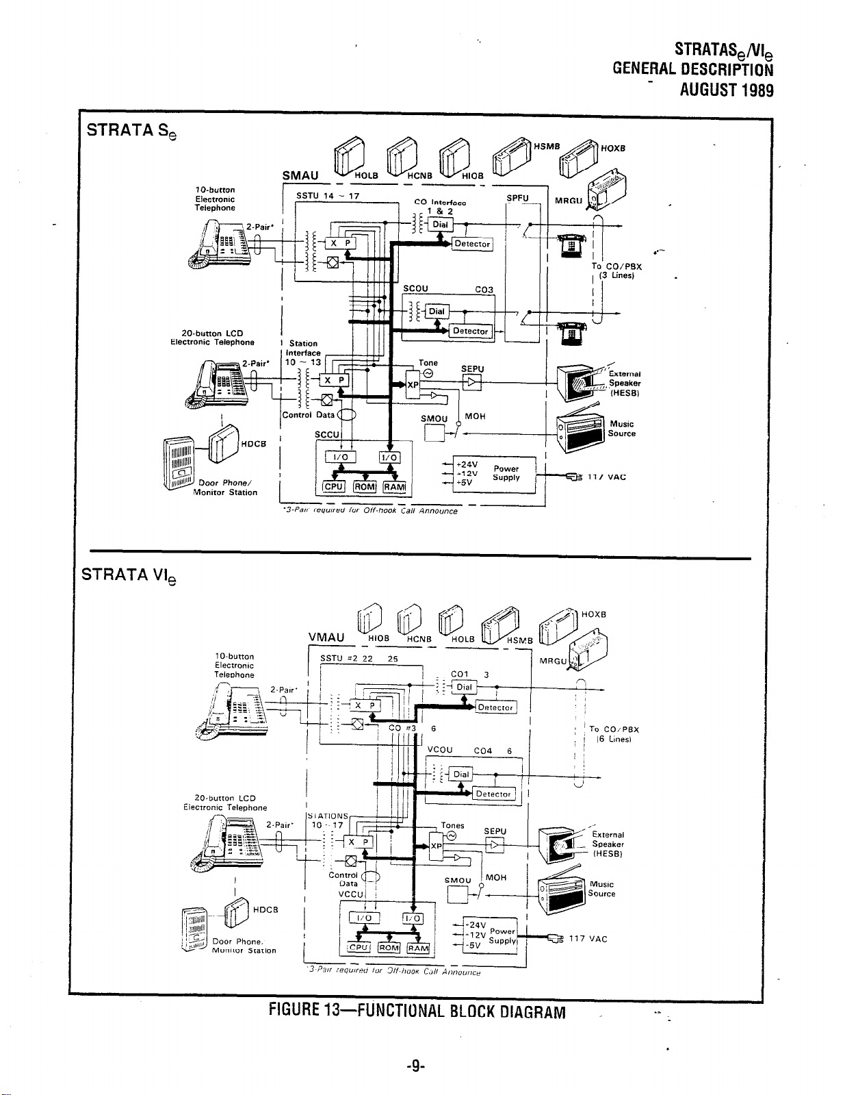
FIGURE 13-FLiNCTI
-9-
DNAL BLOCK DIAGRAM
,*
EXtWnal
Speaker
iHESl3)
-- -e
Page 17
STRATAS,/VI,
GENERAL DESCRIPTION
AUGUST 1989
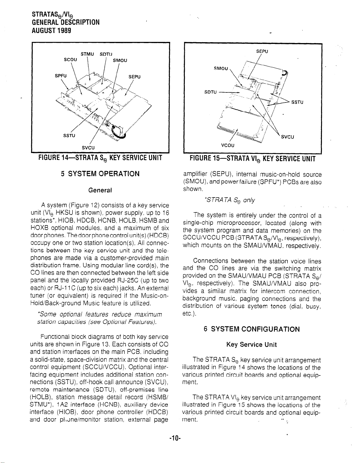
STMU SDTU
FIGURE 14-STRATA S, KEY SERVICE UNIT
5 SYSTEM OPERATION
General
A system (Figure 12) consists of a key service
unit (VI, HKSU is shown), power supply. up to 16
stations”, HIOB, HDCB, HCNB, HOLB. HSMB and
HOXB optional modules. and a maximum of six
door phones. The door phone control unit(s) (HDCB)
occupy one or two station location(s). All connections between the key service unit and the telephones are made via a customer-provided main
distribution frame. Using modular line cord(s), the
CO lines are then connected between the left side
panel and the locally provided RJ-2% (up to two
each) or RJ-11 C (up to six each) jacks. An external
tuner (or equivalent) is required if the Music-on-
Hold/Back-ground Music feature is utilized.
“Some optional features reduce maximum
station capacities (see Optional Features).
Functional block diagrams of both key service
units are shown in Figure 13. Each consists of CO
and station imerfaces on the main PCB. including
a solid-state, space-division matrix and the central
control equipment (SCCU/VCCU). Optional interfacing equipment includes additional station connections (SSTU), off-hook call announce (SVCU).
remote maintenance (SDTU), off-premises line
(HOLB), station message detail record (HSMB/
STMU”), IA2 interface (HCNB), auxiliary device
interface (HIOB), door phone controller (HDCB)
and door pl,~ne/monitor station, external page
SEPU
vcou
FIGURE 15-STRATA VI, KEY SERVICE UNIT
amplifier (SEPU), internal music-on-hold source
(SMOU), and power failure (SPFU*) PCBs are also
shown.
*STRATA Se only
The system is entirely under the control of a
single-chip microprocessor, located (along with
the system program and data memories) on the
SCCUiVCCU PCB (STRATASe/VIe, respectively),
which mounts on the SMAWVMAU, respectively.
Connections between the station voice lines
and the CO lines are via the switching matrix
provided on the SMAU/VMAU PC6 (STRATA Se/
VI,. respectively). The SMAUIVMAU also pro-
vides a similar matrix for intercom connection,
background music. paging connections and the
distribution of various system tones (dial, busy.
etc.).
6 SYSTEM CONFIGURATION
Key Service Unit
The STRATA Se key service unit arrangement
illustrated in Figure 14 shows the locations of the
various printed circuit boards and optional equipment.
The STRATA VI, key service unit arrangement
illustrated in Figure 1.5 shows the locations of the
various printed circuit boards and optional equip-
ment.
.s
-.
-.
-lO-
.
Page 18
STRATAS,/VI,
GENERALDESCRIPTION
- AUGUST1989
NOTE:
The optional modules are used on/y when
required. All internal boards connect to the
main PCB (in some cases, they also attach to
the key service unit’s side panel).
Complete with all available options, both key
service units utilize up to eight printed circuit boards
internally (as shown in Figures 14 and 1.5) and
various option modules. The names and functions
are as follows:
SMAUNMAU: The main printed circuit board of
the key service unit consists of the following
three functions:
a) Station interface: An interface between the
key service unit and up to four stations (Se) or
up to eight stations (VI,), which includes the
solid-state. space-division matrix used for
voice connections between the stations and
the CO/PBX lines. Two-pair wiring is required
for each station; one pair carrying voice and
other pair carrying control data to and from
the station:
b) CO Interface: An interface between the key
service unit and the public telephone network
or PBX for up to two lines (Se) or up to three
lines (VI,). Ring detection, hold and dial
outpulsing for these lines are performed by
this board. Depending upon local CO requirements, each incoming line can be sepa-
rately connected and programmed to provide
DTMF or rotary-dial outpulsing.
CJ Tone: Performs a number of miscellaneous
system functions:
* General system tones
e Provides the switching matrix for the de-
livery of tones for both paging and inter-
com connections.
line(s). Depending upon local CO requirements,
the SCOUNCOU is programmed to. provide
DTMF or rotary-dial outpulsing. The SCOU _
serves one CO line; the VCOU serves up to
three CO lines, and both serve up to three offpremises lines.
SSTU: An optional interface between the key serv-
ice unit and stations 18 - 25 (stations 14 - 17 on
Se). Each SSTU PCB serves up to four stations.
Two-pair wiring is required for each station; one
pair carrying voice and the other pair carrying
control data to and from the station.
SMOU: An optional music-on-hold source that
provides electronic synthesized music. A choice
of two musical tunes are available, selected via
a switch on this board. The SMOU is connected
to the SMAUNMAU via an 8-pin connector.
SEPU: An optional 3-watt amplifier for external
paging. using a customer-supplied 8-ohm
speaker (connected to the SMAUNMAU via a
1 O-pin connector).
SVCU: The Off-hook Call Announce interface that
mounts on the main printed circuit board of the
key service unit to provide OCA access. One
SVCU is required for every eight stations requir-
ing OCA. (Adds two intercom lines in VI,.)
SDTU: Provides Remote AdministrationiMainte-
nance access via its built-in 300/1200 bps
modem. One SDTU per system is required for
Remote AdministratioNMaintenance.
STMU: Required for connection to an HSMB to
provide SMDR for a STRATA Se key service
unit.
SCCUIVCCU: All system control functions are
performed by the single-chip microprocessor on
this printed circuit board. The system program
stored in ROM. RAM for system operations. and
the RAM for system data storage are also lo-
cated on this circuit board. A battery on this
board protects system memory should a power
failure occur.
SCOUNCOd: An optional interface between the
SMAUNMAU and one/three additional CO
HPSU 6120/7120: Each system’s required volt-
ages are provided by one of these factory-
installed power supplies. The HPSU connects to
a standard 3-wire, 117 VAC, 60-Hz, grounded
wall outlet. with a permissible AC input voltage
range of 90 -- 130 VAC.
HPFB: An optional battery backup unit that is
available for the HPSU 6120 (Se). With the
optional battery backup assembly installed, all
functions of the system will continue to operate
Page 19
STRATASJVI,
GENERAL DESCRIPTION
AUGUST 1989
for approximately two to three hours after a loss
of normal electrical power. Calls will not be
disconnected during switch-over to or from battery power.
HPBU-7:
An optional battery backup unit for the
HPSU 7120 (VI,). It is a printed circuit board that
mounts inside the power supply housing and is
connected to the recommended battery pack
(which is customer-supplied, consisting of two
12 VDC. maintenance-free, automobile-type
batteries-80 amp/hour maximum rating). With
the optional battery backup assembly installed,
all functions of the system will continue to oper-
ate for several hours (the actual time period is in
direct ratio to the type and size of batteries se-
lected) after a loss of normal electrical power.
Calls will not be disconnected during switchover to or from battery power. The HPBU-7 also
provides a charge to the battery pack during
normal operations.
Option Modules
HOLB:
HDCB:
HOXB:
An off-premises line module that allows the
bridging of a CO line! which appears in the
system! with a conventional telephone: supervision is provided. Each HOLB provides three
circuits, all three of which may be directed to an
answering machine (or similar device) attached
to the HUNT connector.
An optional module (two per system maxi-
mum) connected to the key service unit at sta-
tion 13 and/or 14 (station 11 and/or 12 on Se)
that allows up to three (each HDCB) door phonei
monitor stations (MDFBs) to ring pre-selected
stations. The HDCB has three outputs (A, 8. C),
which are modular connectors for the three
MDFBs. Outputs B and C may be used for the
Door Lock feature. An alarm monitor can be
used at station 11113C only.
An external module that serves as an
interface between the key service unit and conventional. standard telephones or off-premises
extension (OPX) lines. Each HOXB PCB serves
two extensions: Se supports two HOXBs, VI,
supports four. An HOXB will operate with either
DTMF or rotary-dial telephones. One auxiliary
ring generator/power supply (MRGU) is required
for use with up to three HOXBs.
HSMB:
Serves as an interface between the key ’
service unit and a printer or storage device used
for the SMDR feature. The module is equipped
with an RS-232C interface and connects to the
left side panel via one supplied 8-wire modular
connector (one HSMB per Svstem). (Se also
requires an STMU PCB.) -
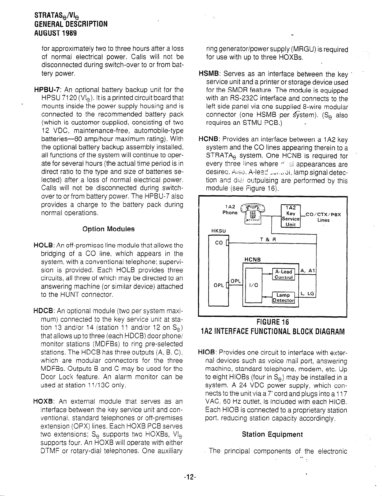
HCNB:
Provides an interface between a IA2 key
system and the CO lines appearing therein to a
STRATA, system. One HCNB is required for
every three lines where (j ::i appearances are
desireo. AI.$IJ. A-IeD-! _._ rVI bLI Ji, lamp signal detec-
tion and cir,; outpulsing are performed by this
module (see Figure 16).
Kev
-CO/CTX/PBX
Lines
’
HKSU
:
co [-
OPL
T&R
HCNB
OPL
1
1 1
FIGURE16
1A2lNTERFACEFUNCTlONALBLOCKDlAGRAM
HIOB:
Provides one circuit to interface with exter-
nal devices such as voice mail port, answering
machine, standard telephone. modem, etc. Up
to eight HlOBs (four in Se) may be installed in a
system. A 24 VDC power supply, which connects to the unit via a 7’ cord and plugs into a 117
VAC! 60 Hz outlet, is included with each HIOB.
Each HIOB is connected to a proprietary station
port. reducing station capacity accordingly.
Station Equipment
The principal components of the electronic
Page 20
STRATAS,/VI,
GENERAL DESCRIPTION
AUGUST 1989
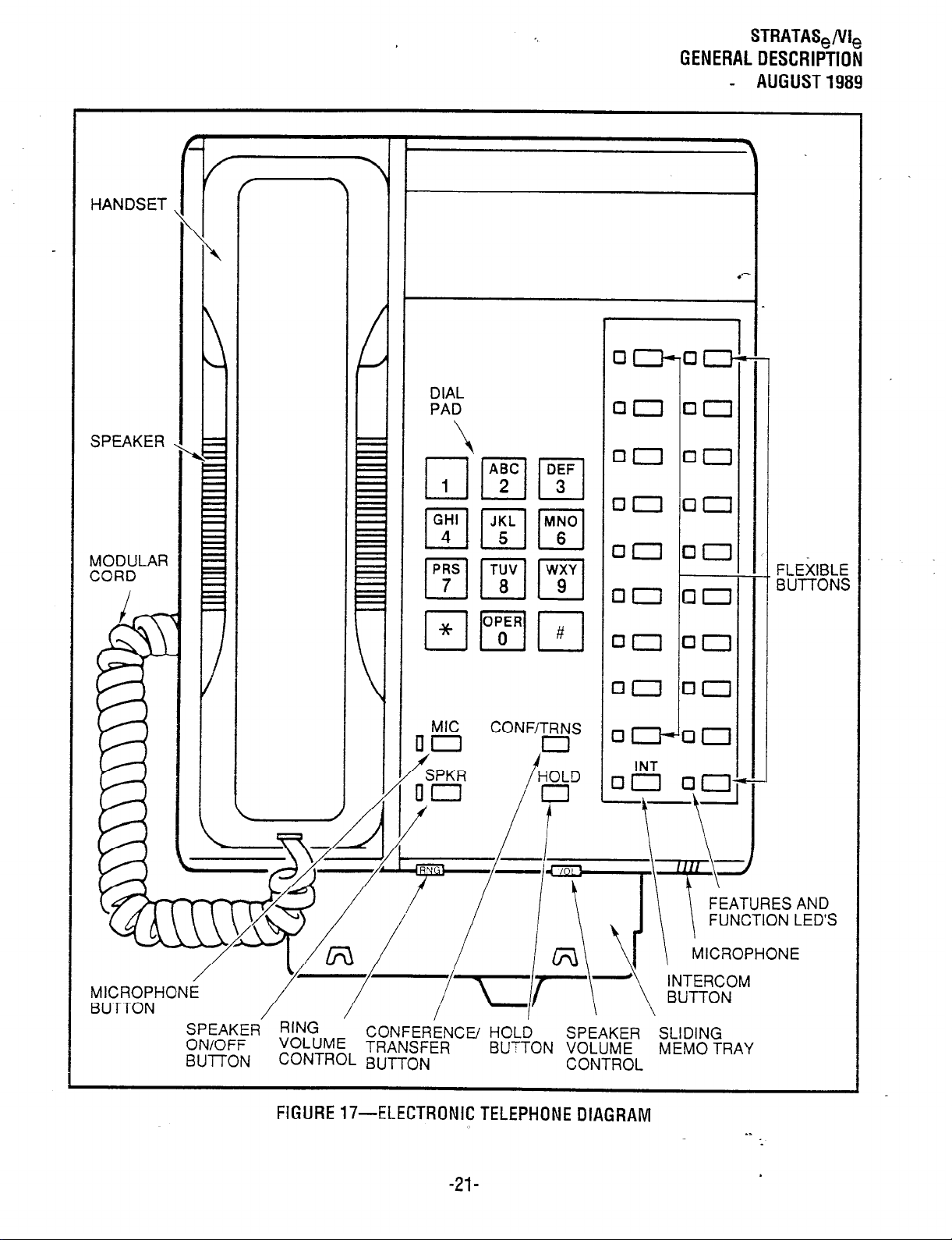
telephone are: handset, dial pad. speaker, microphone, two volume controls, four fixed feature
buttons, an 5 button,
and 9 or 19 flexible CO/
feature buttons, LED indicators are provided for all
buttons except m and m. See Figures 9?
10 and 11.
A 20-button Liquid Crystal Display electronic
telephone (Figure 11) with speakerphone may be
located at any or all of the stations. The 32character alphanumeric display provides many
capabilities-an accurate clock/calendar in its idle
state; and elapsed time, dialed number, calling
station and CO line are just a few of the features
available. For additional explanations of the features listed below, see Liquid Crystal Display.
@ Alphanumeric Messaging
l
Busy Station Messaging
l
Called Station Messaging
l
Calling Station Messaging
l
Remote Station Messaging
l
Busy Lamp Field (BLF) Indication
l
CO Line Identification
l
Speed Dial Memo
l
Timed Reminders
All phones are easily converted for wall mount-
ing, feature .moduiar handset cords. are equipped
with a second modular connector for headset
connection. and are connected to the system via
modular line cords.
The optional door phone/monitor station (Figure 8) ailows distinctive ringing to preselected
station(s). When a station dials an individual door
phone, a circuit providing monitoring capabilities
on the intercom is established. This option requires
station 13 and/or 14 (station I 1 and/or 12 in STRATA
Se) to be replaced by a door phone control unit
(HDCB) and up to six door phone units (MDFBs)-
three each HDCB. One door phone/monitor (only
station 13C for VI,; 11 C for S,) can be replaced by
an alarm control circuit on starion 13/i 1 HDCB and
one by a door lock control circuit on ail HDCBs.
An external amplified speaker (HESB) may be
connected in any one of the following three applications:
l
Loud Ringing Bell:
Allows you to amplify the
tone of a pagingiringing signal without using
other manufacturer’s equipment. Three-pair
wiring is required for this application. .
Amplified Speaker:
Allows you to use the HESB .
as a paging speaker, reducing the need for
other manufacturer’s paging equipment.
Taikback Amplified Speaker:
Allows you to
provide a talkback speaker in areas where a
telephone is not needed. For&alkback opera-
tion, connect the HESB to the door phone unit
(MDFB), which is used as a microphone; however, the push-button is inoperative.
The HESB is a 6” 3-watt speaker with an
amplifier that is built into an attractive speaker box
(Figure 8). A +I2 VDC power supply (HACU-120),
which connects to the back panel via an 8’ cord. is
included with each HESB.
Installation
The key service unit is configured for wall
mounting only.
All external devices are connected to the key
service unit via connectors and terminals on the
side panels as follows:
a) CO lines are connected to the key service unit
right side panel via separate (one for each line)
single-pair modular cords or a single 3-pair
modular cord (Se); or two 3-pair or six singlepair modular cords (Vle).
b) The station connection points are extended
from the key service unit to the main distribution
frame using 3-pair modular line cords. The
individual telephones are connected to the main
distribution frame using 3-pair station cables.
c) A screw-terminal barrier strip is mounted on the
left-hand side of the key service unit to provide
attachment points for the music-on-hold source
input. relay service (Vie only) and external page
output).
d) Two (only one for Se) modular connectors are
also provided on the left side panel for two (only
one for Se) optional off-premises line moduies
(HOLBs).
The power supply is mounted inside the key
service unit. In STRATA Se a connector is provided
on the left side panel for optional system reserve
power (HPFB). In STRATA VI, an optional battery
*
-13-
Page 21
STRATAQVI,
GENERAL DESCRIPTION
AUGUST 1989
backup printed circuit board is available for the
power supply.
Maintenance
Faults in the system are repaired by replac-
ing any faulty component (printed circuit board,
subassembly, telephone, etc.) and returning it to
the manufacturer for repair.
In addition, remote administration/maintenance
allows the system to interface via an SDTU (builtin modem) with a remote location. This reduces the
cost of routine data base changes by eliminating
the need of a technician to be on-site for each
software change.
7 FEATURES and OPERATION
General
This section contains brief descriptions of the
features listed earlier in Tables 6 and C and some
associated operating instructions. For more detailed instructions! see the User Guide or Quick
Reference Guide.
Standard Features
period can be selected for each station.
Automatic Release from Hold:
automatically releases held CO lines if disconnect I
signal is received from the Central Office.
CO Line Call Pickup Groups:
only, this feature, using a dial code or the m
button, allows CO line calls to bepicked up from
another station. Two Call Pickup
defined in programming and buttons (
m can be assigned to phones for each group.
Conferencing:
CO lines and up to three stations (the CO lines
must be conferenced first), or a maximum of
four stations and one CO line. See Amplified
Conference.
CTX/PBX Compatible:
as Toll Restriction and Automatic Dialing, are
compatible with CTX/PBX operation.
CTX Ringing Repeat:
special calling/callback features on CO/CTX/
PBX lines, the system will ring the called station
with the same on/off cadence that is received
from the outside line.
The system will conference two ’
System features. such
To facilitate the use of
The system
In STRATA VI,
System
Ail Call Voice Page:
permits a station user to page via all idle telephone speakers simultaneously. The system
can also be programmed to include the External
Page feature in an All Call Page.
Alternate Point Answer: CO
swered from any station that shares common
CO line appearances.
Automatic Dialing-System:
numbers to be stored in the system memory.
After selecting an outgoing line! any station user
can cause one of the stored numbers to be
outpulsed by dialing the proper access code.
Automatic Hold Recall:
by any station will recall that station after a
programmable period of time. A different time
Dialing a 2-digit access code
calls can be an-
Allows up to 40
A CO line placed on hold
Delayed Ringing:
may be programmed for each station to permit
alternate answering. The delayed ring is pro-
vided for each line selectively by each station.
Distinctive Ringing:
distinguished by different ringing tones.
A 12- or 24-second ring delay
CO and intercom calls are
DTMF and Dial Pulse CO Line Compatible:
system will interface with either DTMF or rotarydial pulse CO lines on a line-by-line basis as
determined by system programming.
Dual FCC Registration:
configured as a key or hybrid telephone system.
with separate FCC registration numbers for each
type. The appropriate configuration for the system is dependent upon its operation. See FCC
requirements on the General End User Information page in the front of this document for
more detail.
Either system may be
The
-14-
Page 22
STRATAS&
GENERAL DESCRIPTION
AUGUST1989
External Page interface:
point is provided for a customer-provided external amplifier/speaker. An SEPU PCB (see External Amplified Speaker and External Page
Amplifier) is mounted in the key service unit
when a customer-provided external speaker only
is used: the output impedance is 8 ohms. This
page circuit can be accessed as part of the All
Call Voice Page feature.
Flexible intercom Numbering:
number can be flexibly programmed up to any 4digit number. It is, therefore, possible to match a
station’s intercom and CTX line extension
number.
3exible Button Assignment:
to be programmed for the optimum use of its CO
or feature buttons.
4exible Line Ringing Assignment:
grammable ring or no ring option is provided for
each iine selectively by each station.
A 600-ohm connection
A station intercom
Allows each phone
A pro-
(13) is the only station that is “down” if it is used
for on-site programming. See Remote.Adminis-
tration/Maintenance.
Message Waiting:
designated Message Center) can set a Mes-
sage Waiting LED at any station with the Message Waiting LED of that s&&ion. The called
station cancels the LED by lifting the handset or
depressing them button. See Flash Button
and Liquid Crystal Display Features.
MF Signal Time (160/80 ms):
dial signal time is 80 milliseconds. but it may be
extended to 160 milliseconds, if required by the
Central Office or to activate remote equipment.
Any station (including the
The standard MF
Multiple Simultaneous Handsfree Intercom
Paths:
systems. Both intercom lines are able to carry
handsfree conversations simultaneously.
(STRATA VI, may be increased to four paths.
optionally.)
Two intercom paths are standard in the
Forced Account Code:
station(s) to dial an account code prior to dialing
a number. Station users can also voluntarily
enter an account code on any CO line call. The
account code is recorded with call details on the
SMDR report.
Group Paging:
82. 83 or 84) permit voice paging to one of four
zones. Zone assignmenr is via software and is
totally flexibie. Paging is via the speakers of idle
telephones.
Special 2-digit access codes (81.
Least Cost Routing:
decide over which trunks outgoing voice and
data calls will be routed. This can greatly reduce
the cost of long distance calling. Three classes
of LCR can be programmed to give priority
routes to the users who need them (VI, only).
Live System Programming:
gramming is accomplished without service interruption to other station users by placing the
system in the special programming mode and
inputting data via station 17 (station 13 in Se) or
RemotekliministrationiMaintenance. Station 17
Requires selected
Enables the customer to
Live system pro-
Music-on-Hold Interface:
for a customer-provided music source. CO lines
placed on hold will be connected to this source.
In addition, this music may also be broadcast
from electronic telephone speakers and external page when the background music programming options are selected.
Night Ringing Answer Code:
may be answered from any station via a dial
code.
Night Ringing Over External Page:
grammable option, while the night mode is active. a system-generated ring tone will be trans-
mitted via the external speaker whenever any
line rings (Vie only).
Night Transfer:
the system can function with two or three ringing
patterns. If three patterns are selected, they are
designated DAY, DAY 2. and NIGHT. If the twopattern mode is selected. DAY and NIGHT
designations are used. In both cases, the ringing
modes are selected with the m button on station 10.
On a programmable optional basis,
An interface is included
A night ringing call
As a pro-
.s
:
.
Page 23
STRATAS,/VI,
GENERALDESCRIPTION
AUGUST1989
Non-blocking Dialing:
CO lines simultaneously.
Outgoing Call Restriction:
selectively restricted from originating calls on
any or all CO lines. However, the station may still
receive calls on the restricted line(s).
Privacy/Non-privacy:
other stations from accessing the intercom or
CO lines that are already in use. A non-private
system provides conferencing on the CO and
intercom lines.
Relay Service:
equipped with two relays that provide the following signals for external equipment:
a)
External page:
ever the external page circuit is accessed, a
dry “make” contact is provided for control of
background music on external page. This is
required only when an external page ampli-
fier is used.
b)
Night Relay Service:
a dry “make” contact at the NR terminals on
the left side panel. A strap option on the
VMAU allows the NR relay to function in one
of two modes:
Answering Machine Control:
1)
remains intact, the relay is operated continuously when the system is in night
service (intended for indirect control of an
answering machine).
Night Bell Control:
2)
relay pulses at a 1 -second on/3seconds
off rate whenever the system is in Night
Transfer mode and an incoming call is
ringing the system (intended for indirect
control of an external night bell).
Station Hunting:
station number and ends with the last station
number in the prearranged group; however! the
call is completed to the first idle number. The
hunting sequence can be either consecutive or
nonconsecutive.
In STRATA VI, only, the VMAU is
Hunting always starts with called
Toll Restriction (6-digit):
on a station class of service basis. The system
performs toll restriction by analyzing the first six
Dialing is permitted on all
Any station can be
A private system prevents
The relay is activated when-
The relay will provide
If the strap
If the strap is cut. the
Selectively programmed
or three digits (area/office code) dialed. Simple
restriction by rejecting the numbers 1 and 1 can
be programmed on a per-station basis, if de-
sired.
Toil Restriction Override by System Automatic
Dialing:
permits numbers stored by the Automatic Dialing-system feature to be calledby toll-restricted
stations.
Trunk-to-Trunk Connection:
to set up a line-to-line connection (tandem switch-
ing), leaving the controlling station free to make
other calls. A maximum of two (simultaneous)
trunk-to-trunk circuit paths can be established.
Voice or Tone Signaling:
tem feature that optionally selects either tone
ringing or voice page as the primary method of
intercom call signaling. The calling station.
however. may choose the alternate method by
dialing 1 following the station number.
Wall Mountable Key Service Unit:
ice unit is designated for wall mounting only.
A programmable system feature that
Allows the system
A programmable sys-
The key serv-
Station
Automatic Callback (Intercom):
tion user who encounters a busy station on
intercom to request a callback by depressing the
dedicated button. The system then monitors the
called station and signals the caller when that
station becomes idle.
Automatic Dialing Buttons:
used with a telephone that includes m buttons
in its programmed assignments.
a) An outside telephone number or station
number can be stored at each m button.
b) A number stored in memory can be sent over
a CO line by depressing the appropriate m
button after accessing the CO line (or an
intercom line after pressing the m button).
NOTE:
Each m button is counted as one of the 40
possible stored numbers available to each
station.
Permits a sta-
This feature can be
. .
-16-
.
Page 24
STRATAS,/VI,
GENERALDESCRIPTION
AUGUST1989
Automatic Dialing-Station: Each station can store
a private list of up to 40 telephone numbers. The
Pause and Flash functions may also be stored
when necessary.
Automatic Off-hook Selection: Allows CO line,
CO group or intercom access by merely lifting
the handset; depressing a CO/Intercom button
is not required.
Busy Override: After calling a busy station and
receiving a busy tone, the caller can dial 4 and
cause a tone burst to be sounded via the called
station’s speaker.
Call Forward: Allows all calls to a station to be
routed to another station. The activating station
may be used to originate calls while this feature
is active.
Call Pickup: Enables a station to pick up calls
ringing at other stations or an external page by
going off-hook and dialing an access code. Gail
Pickup (m) buttons can be assigned to sta-
tions to automatically pick up calls.
Call Transfer with Camp-on: Allows the transfer
of an outside call to a station that is either idle or
busy.
CO/CTX/‘PBX Feature Buttons: Station Automatic
Dialing buttons can be used to store access
codes, plus any flashes or pauses necessary for
feature access in the host switching system.
These are fixed feature buttons and can only be
changed by station 10. Every fixed button assigned to the station reduces the number of m
buttons.
Directed Call Pickup: All calls ringing at another
station can be answered from any station by that
station going off-hook and dialing the ringing
station’s number.
Direct Station Selection (DSS) Buttons: By
depressing an assigned button. a station user
causes the selected station to ring.
Distinctive LED indications:
* lnccming Call: A distinctive flash appears
on the respective LED at the station that is
being called.
l
In-use: A distinctive flash rate shows the line
presently in use at a give station. Other’
stations see a steadily illuminated LED for
that line.
l
On-hold: The station user is shown a distinc-
tive LED flash to indicats-a line placed on
hold at that station. All other stations see the
usual on-hold flash. .
Do Not Disturb: This feature is activated and
deactivated by alternate depressions of them
button. A station calling a station that is in the
DND mode will receive a fast busy tone.
Do Not Disturb Override: After reaching a DND
station, that station may be advised that a call is
waiting by dialing 1. A tone signal will be heard
at the DND station.
DP/MF Mode Chanae (TONE Button): Allows a
e \
station to change between DP and MF modes
via the m button, as required.
Exclusive Hold: Depressing the m button
twice holds that call securely for the station that
placed it on hold.
Executive Override (Break-in): A station pro-
grammed for this feature will override the auto-
matic privacy feature and enter any existing
conversation within the system. A warning tone,
however, is inserted before the overriding station is actually connected. After reaching a busy
station, dial a 9 to override.
Flash Button (CTXIPBX Transfer or CO Dial
Tone Recall): Ten- and 20-button electronic
telephones can
WaitingiFlash (
ipped with a Message
) button which, when
operated while connected to an incoming line,
causes a timed “flash” to be transmitted to that
line. The timing of the flash can be programmed
to signal a CTX/PBX for feature operation or can
be long enough to cause a disconnect and dial
tone recall on a CO line. See Message Waiting.
Handsfree Answerback: All electronic telephones
are equipped for handsfree answerback on voiceannounced intercom calls as a standard feature.
:
-17-
Page 25
S I HA I
AS,/VI,
GENERAL DESCRIPTION
AUGUST 1989
Liquid Crystal Display Features:
features are standard, but require an optional
Liquid Crystal Display telephone to operate.
Alphanumeric Messaging:
a)
and personal messages to be displayed on
the 32-character Liquid Crystal Display. There
are 40 system messages of up to 32 characters in length for use by all LCD telephones
and controlled by station 10. In addition, a
limited number of stations (four in Se, six in
Vie) have IO personal messages avaiiableplus the system messages for the following
features:
l
Busy Station Messaging:
ing a busy LCD station, a message can
be sent to that station (an audible tone will
also be heard). The two stations may respond with LCD messages back and
forth during conversation, creating an
interactive silent messaging conversa-
tion.
l
Called Station Messaging:
number and a message indication may
be sent to another LCD station. When the
called station responds, the station will
receive the 32-character message.
l
Calling Station Messaging:
displayed on your LCD phone will be
automatically displayed on the calling
station’s LCD when dialed.
l
Remote Station Messaging:
station to set a Called Station Message
for another station, the recipient to be a
station or group of stations.
Busy Lamp Field (BLF) Indications:
b)
Liquid Crystal Display can be used to indicate
the on-/off-hook status of all telephones in
the system. BLF status is displayed up to the
maximum number of stations for each system.
CO Line Identification:
cl
to be identified with a 1 &character name. All
LCD phones using that line will display the
name instead of the CO line number.
Speed Dial Memo:
d)
user may program a l&character name for
each of their 40 personal speed dial numbers. The memo pad of names and numbers
(including system names and numbers) may
be scrolled to select the appropriate party.
Allows each CO line
Each LCD telephone
The following
Allows system
When reach-
Your station
A message
Allows any
The
Depressino a CO line button will cause the
displayed number to be dialed automatically.
Limited to four stations on Se and six stations
on Vie.
e) Timed Reminders:
messages to be set at each LCD telephone.
These messages will be displayed at the appropriate times (hour and minute) set by the
station user. The messages-can be repeated
on a daily basis or displayed just once.
Microphone Cut-off Buttons:
phones may be programmed with an m button, allowing the microphone to be turned ON/
OFF while a station is in the idle state (controls
Handsfree .?nswerback).
Modular Handset and Line Cords:
telephones are equipped with modular handset
and line cords, and are also equipped with an
additional modular headset jack.
On-hook Dialing:
your calls with the handset still on-hook. Call
progress can be heard via the telephone speaker;
no need to pick up the handset until your party
answers.
Privacy Override:
feature can enter any existing CO line conversation if the station is equipped with that
button. An initial warning tone is given, but no
subsequent tones are provided. A maximum of
two stations can be programmed for this feature.
The system allows you to dial
A station programmed for this
Private CO Lines:
grammed into the system so that selected CO
line(s) will appear only on selected station(s).
Pushbutton Dialing:
equipped with pushbutton dial pads.
All electronic telephones are
Remote Retrieval of Held Calls:
been placed on hold by a station can be re-
trieved by a different station with the Call Pickup
feature.
Repeat Last Number Dialed:
Allows five separate
Electronic tele-
All electronic
or non-privacy to
button) on CO lines.
q
Restrictions may be pro-
Calls that have
The last number
-5
:
line
-18-
.
Page 26
STRATAS&
GENERALDESCRIPTION
AUGUST1989
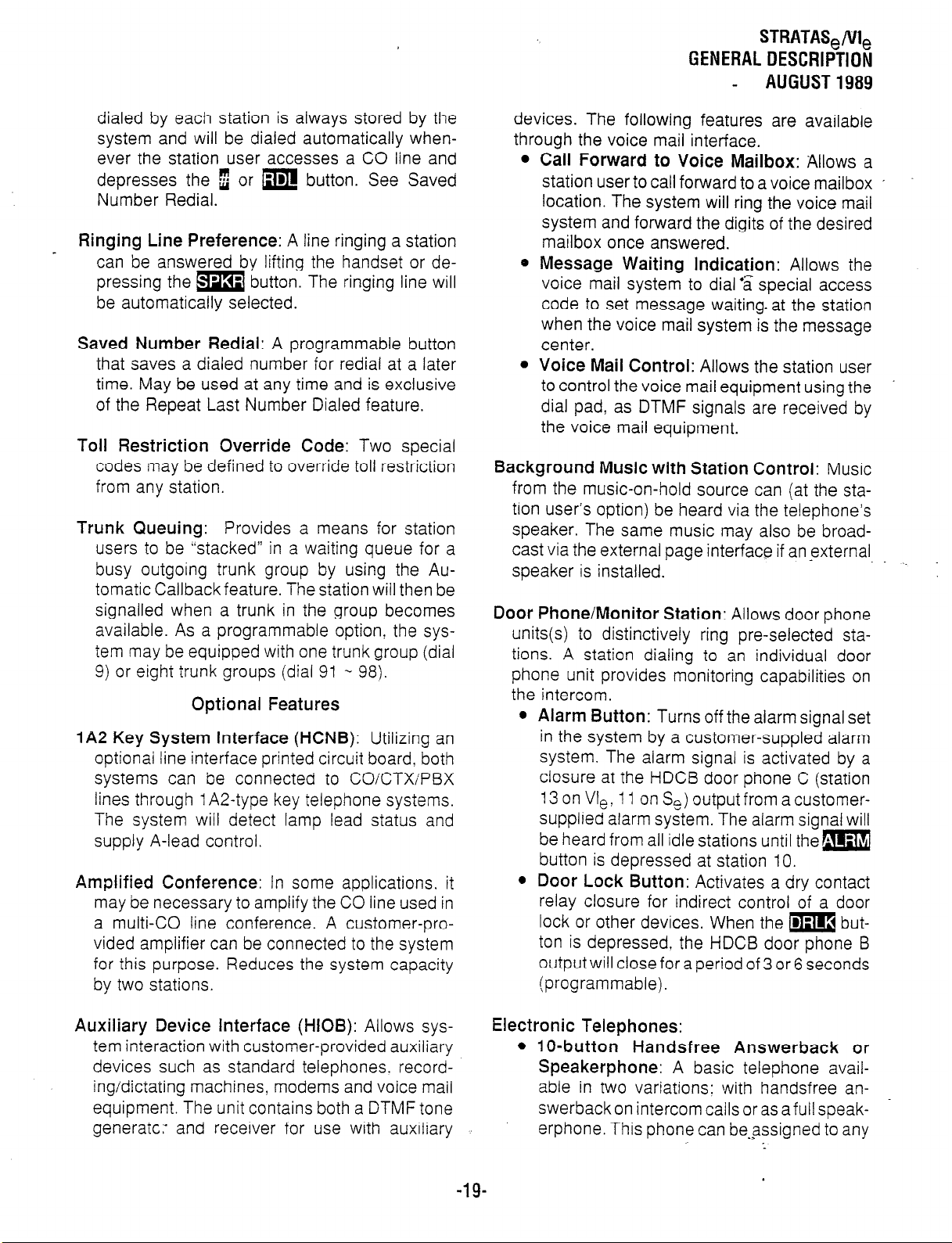
dialed by each station is always stored by the
system and will be dialed automatically whenever the station user accesses a CO line and
depresses the
Number Redial.
Ringing Line Preference:
can be answered bv liftina the handset or depressing the m button: The ringing line will
be automatically selected.
Saved Number Redial:
that saves a dialed number for redial at a later
time. May be used at any time and is exclusive
of the Repeat Last Number Dialed feature.
Toll Restriction Override Code:
codes may be defined to override toll restriction
from any station.
Trunk Queuing:
users to be “stacked” in a waiting queue for a
busy outgoing trunk group by using the Automatic Callback feature. The station will then be
signalled when a trunk in the group becomes
available. As a programmable option the system may be equipped with one trunk group (dial
9) or eight trunk groups (dial 91 w 98).
E or m button. See Saved
A line ringing a station
A programmable button
Two special
Provides a means for station
Optional Features
IA2 Key System Interface (HCNB):
optionai line interface printed circuit board. both
systems can be connected to CO/CTX/PBX
lines through 1 A2-type key telephone systems.
The system will detect lamp lead status and
supply A-lead control.
Amplified Conference:
may be necessary to amplify the CO line used in
a multi-CO line conference. A customer-provided amplifier can be connected to the system
for this purpose. Reduces the system capacity
by two stations.
In some applications, it
Utilizing an
devices. The following features are available
through the voice mail interface.
l
Call Forward to Voice Mailbox:
station user to call forward to a voice mailbox ’
location. The system will ring the voice mail
system and forward the digits of the desired
mailbox once answered.
0 Message Waiting Indication:
voice mail system to dial ‘a special access
code to set message waiting. at the station
when the voice mail system is the message
center.
0 Voice Mail Control:
to control the voice mail equipment using the
dial pad, as DTMF signals are received by
the voice mail equipment.
Allows the station user
Background Music with Station Control:
from the music-on-hold source can (at the sta-
tion user’s option) be heard via the telephone’s
speaker. The same music may also be broadcast via the external page interface if an external
speaker is installed.
Door Phone/Monitor Station:
units(s) to distinctively ring pre-selected stations. A station dialing to an individual door
phone unit provides monitoring capabilities on
the intercom.
0 Alarm Button:
in the system by a customer-suppled alarm
system. The alarm signal is activated by a
closure at the HDCB door phone C (station
13 on Vie: 11 on Se) output from a customersupplied alarm system. The alarm signal will
be heard from all idle stations until them
button is depressed at station IO.
Turns off the alarm signal set
0 Door Lock Button:
relay closure for indirect control of a door
lock or other devices. When the m but-
ton is depressed, the HDCB door phone B
output will close for a period of 3 or 6 seconds
(programmable).
Allows door phone
Activates a dry contact
Allows a
Allows the
Music
Auxiliary Device Interface (HIOB):
tem interaction with customer-provided auxiliary
devices such as standard telephones. record-
ing/dictating machines modems and voice mail
equipment. The unit contains both a DTMF tone
generate: and receiver for use with auxiliary
Allows sys-
Electronic Telephones:
l
lo-button Handsfree Answerback or
Speakerphone:
able in two variations: with handsfree answerbackon intercom calls or as a full speakerphone. This phone can be-assigned to any
-19-
A basic telephone avail-
:
.
Page 27
GENERAL DESCRIPTION
AUGUST 1989
station! and is equipped with an intercom
button and nine flexible buttons that may be
assigned as CO line appearances or feature
access.
l
20-button Handsfree Answerback:
button telephone with handsfree answerback, and is equipped with an Intercom
button and 19 flexible buttons that are assigned as CO line appearances or feature
access.
l
20-button Liquid Crystal Display:
button telephone features a 32-character.
alphanumeric display, with handsfree answerback and full speakerphone capability,
calling station identification, and the same
button flexibility as the 20-button telephone.
See Liquid Crystal Display Features.
External Amplified Speaker:
fied speaker (HESB) may be connected in any of
the following three applications:
Amplified Speaker:
used as a paging speaker.
Loud Ringing Bell:
electronic telephone ring to
An external ampli-
Allows the HESB to be
Allows the tone of an
be
Talkback Amplified Speaker:
talkback speaker (via an MDFB) where a
telephone is not needed.
This 20-
amplified.
Provides a
A 20-
receive a busy signal. Feature is activated automatically or by dial access (I) on a station-by-
station basis.
Off-premises Extension:
lows the system to interface with conventional,
standard telephones or off-premises circuits.
The HOXB serves two extensions and replaces
two stations in the system. (M+aximum: two per
Se/four
*
Off-premises Line:
bridging of a CO/PBX line that appears in the
system with a conventional telephone (or other
device, such as a modem). During Night Serv-
ice. all incoming calls on an HOLB’s three cir-
cuits
(or similar device) connected to the hunt connection. This option is set in programming.
per VI,.)
MRGU:
for the HOXB, one supports up to three
HOXBs.
may be directed to an answering machine
An auxiliary ringinglpower supply
Installing an HOLB allows the
Remote Administration/Maintenance:
ture is provided by the SDTU via its built-in 3001
1200 bps modem. One SDTU per system is
required for Remote Administration/Maintenance.
Installing an HOXB al- ’
This fea-
NOTE:
If an HESB is installed. an external amplifier
(SEPU PCB) is not necessary.
External Page Amplifier:
watt amplifier (SEPU PCB) allows access to a
customer-provided external $-ohm speaker for
paging.
Music-on-Hold Source:
tronic music source (SMOU PCB) eliminates the
need for a customer-provided external music
source and provides electronic-generated music to CO lines placed on hold.
Off-hook Call Announce:
call and speak to an off-hook. busy electronic
telephone through the speaker. The called station user can reply via the telephone’s microphone without interrupting the existing conversation. If the called station is currently in use via
the speakerphoneihandsfree. the caller will
This external page 3-
When installed. this elec-
Allows a station user to
Station Message Detail Recording (SMDR):
Adding an HSMB to a system allows data to be
collected for each outgoing and incoming CO
line call. This data is output to a printer or
recording device via the RS-232C interface
located on the HSMB (which is externally
mounted). Account codes will be included in the
call details (see Forced Account Codes).
System Battery Backup:
a) In STRATA Se. an HPFB can be plugged into
the HPSU to provide automatic switching to
standby battery power. During normal power
conditions, the batteries are kept fully charged
by the power supply. The HPFB includes bat-
teries and the charging unit.
b) In STRATA VI,. an HPBU can be installed in
the power supply to provide automatic switching to standby battery power (provided by
customer). During normal power conditions.
the batteries are kept fully charged by the
power supply.
-2o-
Page 28
HANDSET
SPEAKER
STRATAS,/VI,
GENERALDESCRIPTION
- AUGUST1989
DIAL
PAD
MODULAR
CORD
MICROPHONE
BUTTON
SPEAk---ON/OFr
BUTTON
CER
-7
I--a I # I
0 0 00
00 00
CONF/TRNS o
El
-I. Ih
;‘/y,,,, CONFERENCE/ HOLD SPEAKER SLIDING
Y”L”,“lC
CONTROL BUTTON
--...----
I HANSFER
BUTTON VOLUME MEMO TRAY
CONTROL
J 00
INT
00 qo&
\ \
INTFRPAhl
II. 0 LI I”“,“,
BUTTON
FLEXIBLE
BUTTONS
FiGURElII-ELECTRONICTELEPHONEDlAGRAM
-21-
.>
:
.
Page 29
T(‘JSHIfjA SYSTEM .‘.‘fimC-fi,ii$ ‘I’ ‘-’
WTALLATION INSTRUCTIONS
- JANUARY 1988
5trata Se
RELEASE 2
INSTALLATION INSTRUCTIONS
: /,
‘/
I
.j
i,
;!
i
I
:I
.-z
_
Page 30
TOSHIBA SYSTEM PRACTICES
ELECTRONIC KEY TELEPHONE SYSTEM ’
INSTALLATION INSTRUCTIONS
TABLE of CONTENTS
INSTALLATION INSTRUCTIONS
SECTION 500-036-200
- JANUARY 1988
PARAGRAPH
:i
02.00
030300
03:10
03.20
03.30
040400
04:10
04.20
05
05.00
05.10
05.20
05.30
05.40
05.50
05.60
05.70
05.80
05.90
060600
06:lO
070700
07:10
07.20
07.30
07.40
0:800
08:lO
08.20
08.30
08.40
08.50
09
09.00
09.10
09.20
09.30
09.40
09.50
09.60
09.70
SUBJECT
TABLE of CONTENTS ...............................................
ILLUSTRATION LIST
GENERAL
PACKING .::::::::::::::::::::::::::::::::::::::::::::::::::::::::::
Inspection ........................................................
HKSU REQUIREMENTS .....................................
Cabling Considerations .............................................
Environmental Factors
Power Requirements ..............................................
Main Distribution Frame Requirements
HKSU INSTALL4TION
Mounting the HKSU ...............................................
Power Supply Installation ...........................................
System Ground Check .............................................
PRINTED CIRCUIT BOARD INSTALLATION .............................
General ..........................................................
Factory-Installed PCB ...............................................
scou/vcou .....................................................
SPFU (Se only) ...................................................
SSTU ............................................................
SMOU
SEPU .:::::::::::::::::::::::::::::::::::::::::::::::::::::::::::
svcu ............................................................
SDTU ............................................................
STMU (STRATA Se only) ..........................................
BASIC CABLING REQUIREMENTS ....................................
Station Wiring ....................................................
CO Line Connection
SYSTEM POWER-UP INliiAiiiE’::::::::::::::::::::::::::::::::::::::
General ..........................................................
Clearing Automatic Dialing ........................................
Alphanumeric Messaging Initialization ..............................
Timer Reminder Messaging Initialization ............................
System Real-Time Clock/Calendar Adjustment ......................
EKT INFORMATION
General ..........................................................
HVSU Installation .................................................
EKT Wall Mounting ...............................................
EKT Connections .-, . . . . . . . . . . . .
Carbon Handset Installation . . .
EKT Functional Check . . . . . . . . .
INSTALLATION OF OPTIONS (Exter
Off-hook Call Announce . . . . . . .
HCNB . . . . . . . . . . . . . . . . . . . . . . . .
HIOB
TABLE A-HIOB CAPACITY ....................
HOXB
HDCB ......................................
HOLB ......................................
HSMB
TABLE Bidi:‘jiiC ‘(~&ji~)’ FIN’ ‘~~~~~~flb;(j~
HMDB Installation
TABLE C-VR2 SETTING’S . : : : : : : : :‘: : : : : : : : : : : : :
.......................................
......................................
.................................................
.............................................
.............................
...............................................
.................................................
.............
.............
.............
r
lal) . . . . . . . . . . . . . . . . . . . . . . . . . . . . . . .
.............
.............
.....................
.....................
.....................
....................
....................
.......
.......
.......
.......
.......
.......
.......
.......
..... .-.
:“. ......
*
. . . . . . . .
. . . . . . . .
* . . . . . . .
. . . . . . . .
. . . . . . . .
. . , . . . . .
. . , * . . . .
. . , . . . . .
.3
. . . . . . .--.
. . .
. . .
. . .
. . .
. . .
. . .
. . *
. . .
. . .
PAGE
i
. . .
III
1
1
1
1
1
1
1
f
f
5
5
5
:
7
7
8.-.
ii
8
:
9
10
IO
10
11
:z
12
12
12
13
13
14
14
15
16
16
17
18
18
,
_-
i
Page 31

INSTALLATION INSTRUCTIONS
SECTION 500-036-200
JANUARY 1988
TABLE of CONTENTS (continued)
TOSHIBA SYSTEM PRACTICES
ELECTRONIC KEY TELEPHONE SYSTEM
INSTALLATION INSTRUCTIONS
,
PARAGRAPH
09.80
09.90
10
10.00
10.10
10.20
10.30
10.40
10.50
10.60
10.70
10.80
SUBJECT PAGE
Amplified Conference ............................................. 31
HESB
EO”,pMENT’b6NNECi,ONS’:::::::::::::::::::::::::::::::::‘:-:::::::
Wiring Connections
MOH/BGM Source
External Paging Connections
Direct External Speaker Connection
External Amplifier
Talkback Amplifier ................................................
Background Music ................................................
Volume Setting Sequence
Night Relay Service (Vle only)
................................................ 33:
...............................................
....................................... 34
................................ 34
.................................................
.........................................
..................................... 36
31
33
34
35
E
Page 32

rOSHlBA SYSTEM PRACTICES
.LECTRONIC KEY TELEPHONE SYSTEM
1NSTALIATlON INSTRUCTIONS
ILLUSTRATION LIST
I) INSTALLATION INSTRUCTIONS
SECTION 500-036-200
JANUARY 1988
NUMBER
:
3
-4
5
6
7
9"
10
11
12
13
14
15
16
17
18
::
21
-2
-3
:z
26
z
:;
31
32
33
34
z:
ii
39
tl:
42
43
44
45
:;
48
19
50
51
52
TITLE PAGE
SCCU/VCCU Battery Strap
HKSU Side Covers . . . . . . . . . . . . . . . . . . . . . . . . . . . . . . . . . . . . . . . . . . . . . . . . . .
HKSU Wall Mounting . . . . . . . . . . . . . . . . . . . . . . . . . . . . . . . . . . . . . . . . . . . . . . . .
HPFB Installation . . . . . . . . . . . . . . . . . . . . . . . . . . . . . . . . . . . . . . . . . . . . . . . . . . .
HPBU Installation . . . . . . . . . . . . . . . . . . . . . . . . . . . . . . . . . . . . . . . . . . . . . . . . . . . d- 4
HKSU Cover Removal ...............................................
SCOU and SPFU Locations
VCOU Location
Se SSTU and SVCU Locations
Vle SSTU and SVCU Locations
Se/Vie SEPU and SMOU Locations
Se/Vie SDTU Location
STMU Location
EKT Wiring
RJ-11 C/RJ-25C Color Code
Se/Vie HKSU Right Side Panel
SCCU/VCCU Battery Strap
Se/Vie Initializing Switches
HVSU Location .....................................................
Removing EKT Base
EKT Mounting Holes
EKT Wire Routing
Handset Hanger
Carbon Handset Modification
Off-hook Call Announce Functional Block Diagram
HCNB Connections
HIOB Functional Block Diagram
HIOB Wiring Diagram
HIOB Switches
HOXB Connection Straps
HOXB Wiring .......................................................
HDCB Connection Straps
HDCB/MDFB Connection
HOLB Wiring
HSMB/Printer Cabling
HSMB Straps and Switches
HSMB Buttons
SMDR Printout E~a*mpie’(Outgoing ‘Chili - : : : : : : : : : : : : : : : : : : : : : : : : : : : : : :
SMDR Printout Example (Incoming Call)
HMDB External Switches
HMDB Wiring ......................................................
HMDB Installation
HMDB Internal Switches
Amplified Conference Functional Block Diagram
HESB Back Panel
Modular-to-Terminal Strip Internal Connections
Terminal Strip
Impedance Switch
External Amplifier Hook-up
Volume Setting Controls
Relay Contacts
Night Relay Strapping
.....................................................
.....................................................
.........................................................
................................................
................................................
..................................................
....................................................
..................................................
.....................................................
.......................................................
..................................................
...................................................
......................................................
..................................................
.......................................................
. . . . . . . . . . . . . . . . . . . . . . . . . . . . . . . . . . . . . . . . . .
...........................................
.......................................
......................................
..................................
..............................................
.........................................
......................................
..........................................
.........................................
........................................
....................
......................................
...............................................
............................................
............................................
............................................
..............................................
.........................................
..............................
............................................
............................................
......................
.......................
..........................................
............................................
..........................................
.....
.
-:
.6
10
10
10
11
11
13 _
13
14
14
14
15
17
18
18
:i
2':
;:
26
;:
z
28
29
.>36
37
a
6
7
7
8
8
9
9
. . .
-Ill-
Page 33

INSTALLATION INSTRUCTIONS
SECTION 500-036-200
JANUARY 1968
01 GENERAL
This section describes the installation
es necessary to ensure proper opera?e STRATA Se & Vle systems. lnstalla:edures for the two systems vary only
,n to size; all other factors are the same.
02
PACKING
Inspection
When a system is received, examine all
s and carefully note any visible damage.
image is found, bring it to the attention
delivery carrier and make the proper
Check the number of cartons and the
; of the shipment against the purchase
!d packing slip. If it is determined that
ens are missing, contact your delivery
Imediately. If it is determined that any
nt within a carton is missing, contact
;hiba supplier immediately.
After unpacking (prior to beginning the
or aspect all equipment for damage.
image is detected, contact your delivery
mmediately. If possible, retain all the
packing material.
CAUTION!
handling (installing, removing, exam-
etc.) a printed circuit board, do not
touch the back (soldered) side or the pin
connector. Always hold a PCB by its edge.
02.04 When packing
VCCU), ensure the following:
e Do not use plastic or any type of conductive ’
material for packing a SCCU (or VCCU). Use
plain paper.
CAUTION!
Conductive packing material may cause
the internal backup battery to discharge
and damage the PCB.
02.05 Whenever storing or shipping, always
ensure that the battery strap is in the OFF position (Figure 1). The SMAU/VMAU is a “host”
board for the SCCUNCCU (which is required)
and they are shipped as an assembled unit.
NOTE.
Always make sure the battery strap on the
SCCU/VCCU is in the ON position prior to
instalation.
HKSU cannot operate.
If not, the SET LED on the
or
storing a SCCU (or
.*-
03 HKSU REQUIREMENTS
03.00 Cabling Considerations
03.01 The HKSU must be located so that all
stations are within 1,000 cable feet (305 M) of
it. Acceptable cable is 22 or 24 AWG inside telephone station cable, jacketed but not shielded,
having two or more twisted wire pairs (three
pair required for off-hook call announce).
ATA Se
STRATA Vie
E
E
IRE l-SCCU/VCCU BAITERY STRAP
03.10 Environmental Factors
03.11 Sufficient ventilation should exist to allow dissipation of heat generated by the power
supply and HKSU.
03.12 Humidity at the HKSU location should
be within 20 - 80% without condensation, and
the temperature should be relatively constant
within a range of 32 - 122” F (0 - 50” C). Exposure to dust and airborne chemicals should
also be minimized.
03.20 Power Requirements
03.21 Power for the HKSU (both Se & Vle) is
provided by the power supply (HPSU), which in
turn requires power from a grounded 117 VAC
outlet. The outlet should be separately fused
(dedicated) and rated at 15 amps .~ -
.
-l-
Page 34

INSTALLATION
INSTRUCTIONS
SECTION 500-036-200
JANUARY 1988
03.30 Main Distribution Frame Requirements
03.31 To determine the Main Distribution
Frame (MDF) space requirements, refer to the
following paragraphs:
l
Mounting the HKSU: Paragraph 04.00
l
Station Wiring: Paragraph 06.00
-
l
CO Line Connections: Paragraph 06.20
l
Installation of Options (External): Paragraph
09
l
HKSU Connections: Paragraph 10
04 HKSU INSTALLATION
04.00 Mounting the HKSU
1) Remove both side covers from the HKSU (Figure 2) by pressing in on the two small ribbed
sections on each side cover to free the hold-
ers.
FOUR WALL
FIGURE 2--HKSU
SIDE COVERS
2) Hold the HKSU against the wall in its
planned location and mark the screw locations through the centers of the two keyholes
on the upper sides of the HKSU (Figure 3).
3) Lay the HKSU aside for the moment and start
two screws into the wall at the marked loca-
tions. Use 1%” panhead wood screws and
stop when they have penetrated to half their
depth.
4) Hang the HKSU on the two screws and start
FIGURE 3-HKSU
WALL
MOUNTING
two additional screws in the lower two holes
(Figure 3). Tighten all four screws.
5) Knockouts are provided on top and bottom of
the side covers to permit cables to enter the
HKSU. Remove the appropriate knockouts.
6) Reinstall the side covers.
04.10 Power Supply Installation
04.11 The power supplies used with both sys-
tems are very similar in appearance but provide
different current levels:
l
Se = HPSU 6120
* Vle = HPSU 7120
04.12 The system requires 24 VDC, which is
provided by the internal, factory-installed power
supply (HPSU 6120/7120). The HPSU requires
117 VAC, 60 Hz, with a permissible AC input
voltage range of 90 - 130 VAC.
04.13 In both systems, the HKSU is shipped
with the power supply installed. Use the follow-
ing procedures if it becomes necessary to remove or replace a power supply:
STRATA Se:
1) Turn the system OFF and unplug the power
cord.
.*
:
. ../
-2-
Page 35

INSTALIATION
SECTION 500-036-200
- JANUARY 1988
INSTRUCTIONS
Remove the power supply cable connector at
2)
P7 in the upper left of the SMAU PCB. (It
may be necessary to remove the SEPU PC6
before doing this.)
Remove the ground straps on the right and
3)
left side panels of the HKSU as well as the
two screws at the top corners of the power
SUPPlY.
Pull the top of the power supply forward and
4)
lift the power supply out of the HKSU.
Test the power supply using the procedure
5)
in Paragraph 04.14.
Install the new power supply in the HKSU.
6)
Replace the screws and ground straps re-
7)
moved in step 3.
Reconnect the power supply cable connector
8)
to P7 on the SMAU PCB. (Reinstall the SEPU
PCB if it was removed.)
Plug the power cord in and turn the system
9)
ON.
following voltage check should be performed:
STRATA Se:
Turn the power supply OFF and disconnect ’
1)
the system power cord.
Remove the HKSU front cover.
2)
Disconnect the power suppiy,cabie connector
3)
at P7 in the upper left corner of the SMAU
PCB.
Reconnect the power cord and turn the
4)
power ON.
Using a voltmeter, check the power supply
5)
output voltages at the power supplv cable con-
nector (P7)-per the diagram below:
Verify that the voltages fail within the
6)
ing ranges:
Nominal
t24
+12
+5
Range
+23 - +29
i-1 0.8 - .+13.2.
+4.75
- t5.25
foliow-
STRATA Vie:
1) Turn the system OFF and unplug the power
cord.
2) Remove the power supply cable connector
from Pl in the top center of the VMAU PCB.
3) Remove the ground straps on the right and
left side panels of the HKSU as well as the
two screws at the top corners of the power
supply.
4) Pull the top of the power supply forward and
lift the power suppiy out of the HKSU.
5) Test the power supply using the procedure
in Paragraph 04.14.
6) Install the new power supply in the HKSU.
7) Replace the screws and ground straps removed in step 3.
8) Reconnect the power suppiy cable connector
at PI on the VMAU PCB.
9) Plug the power cord in and turn the system
ON.
if the voltages are correct, go to step 8. If not,
7)
replace the power supply and recheck voitages.
Turn OFF the power.
8)
Connect the power supply cable connector
9)
back to P7 on the SMAU PCB.
10) Reinstall the HKSU cover, and turn the
power back ON.
STRATA Vie:
1) Turn OFF the power and unplug the power
cord from facility power.
2) Remove the front cover from the HKSU.
3) Disconnect the power supply cable connector
Pl at the top center of the VMAU PCB (just
below the power supply).
4) Reconnect the power cord and turn the
power ON.
5) Using a voltmeter, check the power supply
output voltages at the power supply cable connector (Pl ) per the diagram below:
04.14 if power supply problems are suspected
or if a new power supply is being installed, the
6) Verify that the voltages fall within the foilowing ranges: -3
-3-
Page 36

LA1 IUN INSTRUCTIONS
N
500-036-200
RY
1988
Nominal
+24 +23 - +29
+12
+5 t4.75
? voltages are correct, go to step 8. If not,
Ice the power supply and recheck volt-
‘.
OFF the power.
lect the power supply cable connector
to PI on the VMAU PC8
nstall the HKSU cover, and turn the
ver back ON.
Optional power backup units are avaii-
both systems:
HPFB
HPBU-7
4 Se:
:B is a separate unit that connects to the
panel of the HKSU via a 2-wire connecIre 4).
:o three HPFB modules may be con?d together in parallel to extend the
?r backup time. With the optional battery
up assembly installed, the system will
nue to operate after a facilities power
.e. The actual time period depends on
system configuration/application and
,er of battery backup modules used.
Range
t10.8 -
t13.2
- t5.25
STRATA We:
The HPBU-7 is a PCB that mounts inside the
power supply housing (Figure 5) and is con-
netted to the female 3-prong connector inside
the power supply’s case. Secure the HPBU with
the two provided screws.
* The HPBU is then connected via the terminal
block to the recommended battery pack
(which is customer-supplied, consisting of
two 12 VDC, maintenance-free, automobile-
type batteries-80 amp/hour maximum rat- a
ing). With the battery backup assembly installed, all functions of the system will
continue to operate for several hours after
a facilities power failure (the actual time pe-
riod is in direct ratio to the type and size of
batteries selected).
.
1GlJRE 4-HPFB INSTALLATION
FiGURE 5-HPBU INSTALLATION
04.16 When installing or removing the HPBU,
perform the following:
WARNING!
When installing the HPBU-7 in the power
supply, care must be taken against accidental shorts that may injure the installer
or damage the power suppiy.
1) Turn
2) Remove the front cover from the HKSU.
3) Remove the metal plate on the left side of
-4-
OFF
the power and
power cord.
the power supply case (two screws).
unplug
the system
.s
:
Page 37

INSTALLATION
SECTION 500-036-200
_ JANUARY 1988
INSTRUCTIONS
4) Connect the 4-wire connector extending
from the rear of the HPBU-7 inside the power
supply case as shown in Figure 5.
5) Mount the HPBU-7 with the two screws removed in step 3.
6) Connect the positive terminal on one battery
to the negative terminal of the other battery
(in series).
7) Connect the free negative battery terminal to
the negative terminal on the HPBU-7.
8) Connect the free positive battery terminal to
the positive terminal on the HPBU-7.
04.20
04.21 Both Toshiba telephone systems require a solid earth ground. Failure to provide
such a ground may lead to confusing trouble
symptoms in the system and, in extreme cases,
circuit board failure. In most installations (within
the continental United States), the ground provided by the “third wire ground” at the commercial power outlet will be satisfactory for all system requirements.
percentage of installations, this ground may be
installed incorrectly. Therefore, prior to installing
a system, the third wire ground must be tested
for continuity by either measuring the resistance
ground) and a metal cold water pipe, or by using
a commercially available earth ground indicator.
If neither procedure is possible, then the follow-
ing test procedures should
Hazardous voltage is exposed during the following test. Use great care when working
with AC powerline voltage.
1)
2)
3)
4)
System Ground Check
However, in a small
between
Obtain a suitable voltmeter and set it for a
possible reading of. up to 250 VAC.
Connect the meter probes between the two
main AC voltage points on the wall outlet.
The reading obtained should be 90 - 130
VAC.
Move one of the meter probes to the third
prong terminal (GND). Either the same read-
ing or a reading of 0 volts should be obtained.
If the reading is OV, leave one probe on the
GND tei,-ninal and move the other probe to
the third prong terminal (earth
be
performed.
WARNING!
the second voltage terminal. If a reading of
OV is obtained on both voltage terminals, the
outlet is not properly grounded. Omit steps
5 through 7 and proceed directly to step 8. ,
If a reading of OV on one terminal and a read-
5)
ing of 90 - 130 VAC on the *other terminal
is not obtained, the outlet is not properly
grounded. Omit steps 6 and-7 and proceed
directly to step 8.
If a reading of OV on one terminal and a read-
6)
ing of 90 -
is obtained, remove both probes from the out-
let.
Set the meter on the “OHMS/Rxl” scale,
7)
place one probe on the GND terminal and the
other probe on the terminal that produced a
reading of OV. A reading of less than 1 ohm
should be obtained. If a reading of more than
1 ohm is obtained, the outlet is not adequately grounded.
If the above tests show the outlet is.improp-. .
8)
erly grounded, that condition should be cor-
rected
250 of the National Electrical Code) before
the system is connected.
05 PRINTED CIRCUIT BOARD
05.00 General
05.01 Complete with all available options,
both systems utilize up to ten (Se) or eight (Vle)
printed circuit boards internally and various op-
tion modules. The names and functions are as
follows
05.02 The SMAU/VMAU and SCCU/VCCU
are factory-installed in the HKSU.
05.03 If any optional PCBs (SSTU, SEPU,
STMU, SMOU, SPFU, SVCU, SDTU or SCOU/
VCOU) are required, refer to Figure 6 and re-
move the HKSU cover as follows:
1) Remove both side covers by pressing in on
the two small ribbed sections on each cover
to free the holders.
2) Remove three screws from each side of the
HKSU per Figure 6.
3) Lift the HKSU cover off. -_
130 VAC on the other terminal
by
a qualified electrician (per Article
INSTALLATION
:
-5-
Page 38

INSTALLATION INSTRUCTIONS
SECTION 500-036-200
JANUARY 1988
RElMOVE SIX
COVER SCREWS
0
FIGURE 6-HKSU COVER REMOVAL
05.10 Factory-Installed PCBs
05.11 SMAUIVMAU: The main printed circuit board of the key service unit consists of the
following three functions:
livery of tones for both paging and intercorn connections.
05.12
SCCU/VCCU:
All system. control
functions are performed by the single-chip micro-’
processor on this printed circuit board. The system program stored in ROM, RAM for system
operation, and the RAM for system data storage
are also located on this circuit board. A battery
on this board protects systemt’filemory should a
power occur.
05.13 See Figure 1 and verify that the battery
strap on the SCCU/VCCU is in the on position.
05.14 The SMAU/VMAU and SCCU/VCCU
PCBs are factory-installed in the HKSU. If repair
of either PCB is necessary, the HKSU should be
replaced and returned to your supplier.
05.20 SCOU/VCOU
05.21 An optional interface between the
SMAUIVMAU and one/three additional CO
line(s). Depending upon local CO requirements,
the SCOU/VCOU is programmed to’ provide
DTMF or rotary-dial outpulsing. The SCOU
serves one CO line; the VCOU serves up to
three CO lines, and both serve up to three offpremises lines.
. .
a) Station Interface: An interface between the
key service unit and up to four stations (Se)
or up to eight stations (We), which includes
the solid-state, space-division matrix used for
voice connections between the stations and
the CO/PBX lines. Two-pair wiring is required for each station; one pair carrying
voice and the other pair carrying control data
to and from the station.
b) CO Interface: An interface between the key
service unit and the public telephone network
or PBX for up to two lines (Se) or up to three
lines (We). Ring detection, hold and dial out-
pulsing for these lines are performed by this
board. Depending upon local CO requirements, each incoming line can be separately
connected and programmed to provide DTMF
or rotary-dial outpulsing.
c)
Tone:
Performs a number of miscellaneous
system functions:
l
Generates system tones.
a Provides the switching matrix for the de-
HOLES
P8 SPFU
FIGURE 7-SCOU and SPFU LOCATIONS
-3
:
-6-
Page 39

INSTALLATION INSTRUCTIONS
SECTION 500-036-200
- JANUARY 1988
STRATA Se:
05.22 The SCOU PCB mounts on four lo-pin
connectors at the bottom of the SMAU PCB into
PlO, PI 1, PI2 and P13 connectors (Figure 7).
Secure the SCOU PCB to the right side panel
with the two provided screws.
- STRATA Vle:
05.23 The VCOU PCB mounts on four lo-pin
connectors and one plastic standoff at the bottom of the VMAU PCB (Figure 8). Install the
VCOU’s three lo-pin connectors into the
VMAU’s P6, P7 and P8 connectors. Secure the
VCOU to the left and the right side panels with
two provided screws on each side.
tors into P14, P15 and
SMAU PCB. Secure the SSTU PCB to the right
side panel with the two provided screws Route
the provided jumper cable from the SSTU P19
connector to the P19 connector on the SMAU
to provide crosspoints for stations 14 - 17.
NOTE:
Jumper cable is necessary only when OCA
is equipped.
P16
connectors on the
’
FIGURE 8-VCOU LOCATION
05.30 SPFU (Se only)
05.31 An optional PCB with relays to connect
the CO lines to three standard telephones if a
power failure occurs.
05.32 Install into the connector marked SPFU
at the bottom of the SMAU PCB (Figure 7).
05.40 SSTU
05.41 An optional interface between the key
service unit and stations 14 - 17 (stations 18
- 25 on STRATA We). Each SSTU PCB serves
up to four stations. Two- or three-pair wiring is
required for each station; one pair carrying voice
and the other pair carrying control data to and
from the station (the third pair is required for
OCA).
STRATA Se:
05.42 For adding stations 14 - 17, refer to Fig-
ure 9, and insert the three SSTU lo-pin connec-
FIGURE g--Se SSTU
STRATA Vie:
05.43 For adding stations 18 - 21, refer to Figure 10, and insert the three SSTU lo-pin connectors into P9, PlO and Pl 1 connectors on
the VMAU PCB. Secure the SSTU PCB to the
right side panel with the two provided screws.
(For stations 22 -
connectors on another SSTU into P12, P13 and
PI4 connectors on the VMAU PCB. Secure the
SSTU PCB to the right side panel with the two
provided screws.)
a) Route the provided jumper cable from the
SSTU P19 connector to the P21 connector on
the VMAU to provide crosspoints for stations
18 - 21.
b) Route the provided jumper cable from the
SSTU P19 connector to the P23 connector
on the VMAU to provide crosspoints for stations 22 - 25.
NOTE:
Jumper cable is necessary only when OCA
is equipped. .3
and SVCU LOCATIONS
25, insert the three lo-pin
:
-7-
.
Page 40

INSTALLATION
INSTRUCTIONS
SECTION 500-036-200
JANUARY 1988
FIGURE IO-Vie SSTU and SVCU LOCATIONS
05.50 SMOU
05.51 An optional music-on-hold source that
provides electronic synthesized music. One or
two musical tunes are available, selected via a
switch on this board. The SMOU is connected
to the SMAU/VMAU via a 7-pin connector.
STRATA Se:
05.52 Install the SMOU PCB into connector
P6 on the upper center of the SMAU PCB (Fig-
ure 11).
STRATA We:
05.53 Install the SMOU PCB into connector
P16 on the upper center of the VMAU PCB (Figure 11).
05.60 SEPU
05.61 An optional 3-watt amplifier for external paging, using a customer-supplied 8-ohm
speaker (connected to the SMAU/VMAU via a
1 O-pin connector).
STRATA Se:
05.62 Install the SEPU into connector P5 on
the SMAU PCB (Figure 11). Slide the SEPU’s
corner hole over the white, plastic standoff sup-
port. Secure the SEPU to the left side panel with
two screws.
FIGURE ll-Se/Vie SEW and SMOU LOCATIONS
STRATA Vie:
05.63 Install the SEPU into connector P15 on
the VMAU PCS (Figure 11). Slide the SEPU’s
corner hole over the white, plastic standoff support. Secure the SEPU to the left side panel with
two screws.
05.70 svcu
05.71 The Off-hook Call Announce interface
that mounts on the main PCB of the key service
unit to provide OCA access. One SVCU is re-
quired for every eight stations requiring OCA.
(Adds two intercom lines and two OCA paths in
STRATA We.)
STRATA Se:
05.72 Insert connector PI on the SVCU into
the P20 connector on the SMAU (Figure 9).
STRATA Vie:
a) To provide OCA to stations 10 - 17, refer to
Figure 10, and insert connector Pl on the
SVCU into the P25 connector on the VMAU.
b) To provide OCA to stations 18 - 25, insert
connector Pl on the SVCU into the P26 connector on the VMAU.
05.80 SDTU
05.81 Provides Remote Administration/Main-
.%
-.
-8-
Page 41

tenance access via its built-in 300/l 200 bps mo-
dem. One SDTU per system is required for Remote Administration/Maintenance.
STRATA Se:
05.82 Insert connectors Pl and P2 on the
_ SDTU into the P8 and P9 connectors on the
SCCU (Figure 12). Route the provided jumper cable from the SDTU P3 connector to the P22 connector on the SMAU.
INSTALLATION INSTRUCTIONS
SECTION 500-036-200
- JANUARY 1988
t-we for clarity
FIGURE 1 2-Se/We SDTU LOCATION
STRATA Vie:
05.83 Insert connectors Pl and P2 on the
SDTU into the P8 and P9 connectors on the
VCCU (Figure 12). Route the provided jumper ca-
ble from the SDTU P3 connector to the P29 connector on the VMAU.
05.90 STMU (STRATA Se only)
05.91 Required for connection to an HSMB to
provide SMDR for a STRATA Se HKSU.
05.92 Refer to Figure 13, and insert connec-
tors P4 and P5 on the STMU into the P4 and
P5 connectors on the SCCU. Route the provided
jumper cable from the STMU P23 connector to
the P23 connector on the SMAU.
FIGURE 13-STMU LOCATION
06 BASIC CABLING REQU!REMENTS
06.00 Station Wiring
06.01
signed permanently to specific cable appearances in the system. Make sure the station cables are connected to the proper terminals.
06.02 Using the industry-standard color code
sequence, terminate the individual 2- or 3-pair
station cables consecutively on the MDF (3-pair
cabling required for OCA). Connect the HKSU cable pairs to the station cable pairs.
When installing station cable, do not run
parallel to and within 3’ of an AC power
line. Such power lines should be crossed
at right angles (90”) only.
06.03 At the station locations, terminate the
station cable in a conventional 4- or 6-conductor
modular station connector to accommodate the
modular line cord from the EKT. The standard
modular EKT cord length is 7’, while the maximum allowed length is 25’. Figure 14 shows
the EKT wiring arrangement.
06.04 Various manufacturers of modular station blocks have employed different color codes
to indicate the sequence of pairs in their blocks.
However, the color code most commonly used
is shown in Figure 15. Verify the configuration
Intercom codes (station numbers) are as-
WARNING!
-9-
.
Page 42

INSTALLATION INSTRUCTIONS
SECTION 500-036-200
JANUARY 1988
STRATA Se STRATA Vie
FIGURE 14-EKT WIRING FIGURE 16-Se/Vie HKSU RIGHT SIDE PANEL
of your modular blocks before connecting the sta- then terminates directly into a locally provided
tion cables. RJ-25C jack (Figure 15).
NOTE:
White and blue (T3 & R3) are used for OCA
voice pair on station line connectors.
SINGLE PAIR RJ-11 C WIRING
TO CO/PBX
\
-----
L---i
TT) HKSU
FIGURE 15-RJ-11 C/RJ-25C COLOR CODE
06.10 CO Line Connection
06.11 The CO/PBX lines are connected to the
system via 6-wire modular line cords (no longer
than 25’) that are connected directly to the
HKSU’s right side panel (Figure1 6)-CO1 modular connector on Se; l-3 and 4-6 modular connectors on Vie. The opposite end of each cord
06.12
nected via 2-wire modular line cords to connec--
tors COl, C02, and CO3 (Se) or connectors 1-3,
4-6, 2, 3, 5 and 6 (Vle) on the right side panel
(Figure 16). The opposite end of each cord then
terminates directly into a locally provided RJ-
11 C jack (Figure 15).
The CO/PBX lines may also be con-
07 SYSTEM POWER-UP INITIALIZE
07.00 General
07.01
ments (stored in ROM) can be entered at any
time by performing the initialize sequence out-
lined below. The system must be initialized
when it is first installed or whenever the SCCU/
VCCU PCB is changed. This will allow the system to be tested and any faults to be corrected
before time is spent on programming.
NOTE:
Do
battery-protected SCCU/VCCl.J.
07.02 Refer to Figure 17 and verify that the
battery on the SCCU/VCCU is connected to ensure that data changes entered after initialization will not be lost due to power failure.
NOTE.
The SET LED will not function if the SCClJ/
A list of standard system data assign-
not
initialize if using a preprogrammed,
VCClJ battery is not connected.
-3
Page 43

STRATA Se STRATA Vie
I 1.
INSTALLATION INSTRUCTIONS
SECTION 500-036-200
_ JANUARY 1988
4) Dial 3 a B on the dial pad.
5) Depress the 01 and 03 keys on station 13.
l
The corresponding LEDs go on.
6) Depress the m;T1T;l key on station 13.
l
Station 13: All LEDs (except SPKR and
MIC) begin blinking.
7) Depress and release the S&J switch again.
l
SET LED goes off.
l
Station 13: LEDs go off. -
,
FIGURE i 7-SCCU/VCCU BATTERY STRAP
07.03 To initialize STRATA Se system data
memory, refer to Figure 18, temporarily connect
a 20-key EKT to station 13, and perform the fol-
lowing:
STRATA Se
STRATA We
n’O]~~
rQ
f=Ji
LJ
43
SET
•l
8) Cycle the power switch
07.04 To initialize STRATA Vie system data
memory, refer to Figure 18, temporarily connect
a 20-key EKT to station 17, and perform the following:
1) Place the system power switch
ON position.
2) Depress the
panel, and hold it in.
3) Depress the
* SET LED goes on.
8 Station 17: All LEDs except SPKR and
MIC flash continuously.
4) Depress and release the
@ SET LED goes off.
l
Station 17: All LEDs go off.
5) Release the
6) Cycle the power switch
07.10 Clearing Automatic Dialing
INT
switch on the left side
SET
switch and allow ifto lock: .-
INT
switch.
OFF
and ON.
(POW)
SET
switch again.
OFF
and ON.
in the
FIGURE 1 8-Se/Me INITIALIZING SWITCHES
1) Place the system power switch in the ON position.
2) Depress the
d SET LED goes on.
@ Station 13: LED 19 goes on.
3) Depress the m key on station 13.
@ Statibn 13: SPKR LED goes on.
SET
switch and allow it to lock.
07.11 The Automatic Dialing memory con-
tains random numbers when the system is pow-
ered up initially. Therefore, it is necessary to
clear the memory to prevent meaningless
numbers from being dialed.
IMPORTANT!
Station 13/l 7 may be equipped with ei-
ther a lo- or a 20-key EKT. Prior to performing the procedure that follows (if a
IO-key is to be used), refer to Paragraph
02.201’Figure 1, Programming Procedures,
Section 500-036-300, for instructions on
using a 1 O-key EKT for programming.
07.12 To clear the Automatic Dialing (-System
and -Station) memory (up to 40 numbers), proceed as follows:
-11
._
:
Page 44

INSTALLATION INSTRUCTIONS
SECTION 500-036-200
JANUARY 1988
1) Lock in the SET switch.
* Station 13/17: LED 19 lights steadily.
2) To clear station automatic dialing, depress
the m key and dial 11 a.
l
SPKR LED flashes continuously.
e Depress keys mm a a.
0 Depress the m key.
_ 3) To clear system automatic dialing, depress
the m key and dial a 1 a.
l
SPKR LED flashes continuously.
0 Depress keys
l
Depress the m key.
q q q q
.
4) Release the SET switch.
l
The SET LED and LED 19 on station
13/17 go off.
07.20 Alphanumeric Messaging
Initiaiiza-
tion
NOTE:
There are 40 messages available in system
memory (60 - 99), and 10 available at
each station (10 - 19).
07.21 To initialize system alphanumeric mes-
sages, follow these procedures:
62:
CALL
BACK AT
63:
64:
RETURN ON
07.30
Timer Reminder Messaging Initializa- ’
tion
07.31
To clear Timer Reminder messages, fol-
low these procedures:
1) Lock in the SET switch.
.-
@ Station 13/17: LED 19 lights steadily.
2) To clear timer codes, depress the m key
and dial 4 p 1.
l
SPKR LED flashes continuously.
l
Depress keys
l
Depress the m key.
q q
QJ a.
07.40 System Real-Time Clock/Calendar
Adjustment
07.41 The following procedures detail how to
set the date, time and day in the system.
NOTE:
This operation is possible from station 10
only.
1) Handset on-hook.
‘1~
1) Lock in the SET switch.
l
Station 13/l 7: LED 19 lights steadily.
2) To clear codes 60 - 99, depress the w
key and dial 3 j 9.
l
SPKR LED flashes continuously.
@ Depress keys a a a a.
l
Depress the m key.
07.22 To initialize station alphanumeric mes-
sages, follow these procedures:
1) Lock in the SET switch.
0 Station 13/17: LED 19 lights steadily.
2) To clear codes 10 - 19, depress the m
key and dial 3 0 a.
0 SPKR LED flashes continuously.
e Depress keys a a a q .
l
Depress the TxI’TIT;I key.
NO TE.
System messages can only be programmed
or changed at station 10. When the system
is initialized, five messages are automati-
cally stored in memory..
60:
OUT TO LUNCH
61:
IN A MEETING
2) To set date:
Dial a i Q 1 (or m m 1 I).
4
Dial in date (year/month/day) in the for-
b)
mat WMMDD. Enter a leading 0 for singledigit month and day.
Depress the 4 (or m) key.
d
3) To set time:
a) Dial 3 i Q a (or m m i 3).
b) Dial in time (hour/minute/second) in
24-hour clock format HHMMSS. Enter a
leading 0 for single digit.
c) Depress the 3 (or m) key.
4) To set day:
a) Dial 1 i !J B (or mm 11).
b) Dial in the day (0 represents Sunday, s
Monday, etc., through 3 for Saturday).
c) Depress the a (or m) key.
08 EKT INFORMATION
08.00 General
08.01 Eight different electronic key tele-
phones (EKTs) may be used in the system. See
the
General Description
tions of the EKTs.
for complete descrip-
-12-
Page 45

08.02 All EKTs share the same dimensions:
Height: 3.7” (94 mm)
Width: 7.1” (180 mm)
Depth: 9.5” (241 mm)
08.03 All EKTs feature modular handset cords
and are connected to the system via 4-conductor modular line cords. With the exception of the
single-line EKT, all EKTs are also equipped with
an additional modular headset connector. In addition, each EKT model may be used at any or
all stations.
08.10 HVSU Installation
INSTALLATION INSTRUCTlONS
SECTION 500-036-200
_ JANUARY 1988
08.11
hook Call Announce (OCA) calls via intercom
dialing, transfer/conference dialing, or Direct
Station Selection. There are no special requirements to enable EKTS to originate OCA calls.
08.12 However, EKTs which are able to re-
ceive OCA calls:
@ Must be equipped with an HVSU PCB.
l
08.13 Follow the instructions below to install
an HVSU.
1) Loosen the four screws holding the bottom
2) Remove the HVSU label from the HVSU and
NOTE.
This step is very important so that an
equipped EKT may be easily identified.
3) Plug the HVSU into the P5 connector on the
All Toshiba EKTs may originate Off-
Must be equipped with a 3-pair modular
cord.
cover of the EKT and remove the cover.
attach it to the EKT label.
bottom of the EKT main board (Figure 19).
FIGURE 19-HVSU LOCATION
08.23 Locking tabs secure the EKT’s base.
The direction in which the base.is attached to
the EKT determines whether it is used as a desk
unit or wall unit (it is factory-configured as a
desk unit). To wall-mount an EKT, perform the
following steps:
1) Disengage the locking tabs by pushing downward on the base (Figure 20), and then rotate
the base 180” and insert it into the lower
four locking slots.
4) Reinstall the EKT bottom cover and tighten
the four screws.
08.20 EKT Wail Mounting
08.21
manner, and they may be mounted on a wall
or any other flat, vertical surface to which the
base can be secured. When selecting the mount-
ing site, consider the EKT’s weight and the additional stresses to which the mounting will be
subjected.
08.22 Mounting screws or mollies, appropriate for the surface on which the telephone is
to be secured, must be provided by the installer.
All EKTs are mounted in the same
-13-
FIGURE 20--REMOVING .EKT BASE
:
Page 46

INSTALLATION INSTRUCTIONS
SECTION 500-036-200
JANUARY 1988
2) Route the line cord through the notch in the
bottom of the EKT.
3) Secure the unit to the desired wall site. (Use
dimensions shown in Figure 21 to position
the unit.)
KNOCKOUT
FIGURE 21-EKT MOUNTING HOLES
4) Route the tail cord through the holes in the
base and secure the EKT (Figure 22).
the cutout just above the hanger (Figure 23),
disengage the hanger’s locking tabs, and
slide the hanger out. Rotate the hanger 180”
and reinsert it. Note that the hanger mates ,
with the notch in the handset.
HANDSET
HANGER
FIGURE 23-HANDSET HANGER
08.24 An optional 13’ handset cord is available from your Toshiba supplier, and it-is sug-
gested that this cord be used when wall mounting an EKT.
08.30 EKT Connections
08.31 Connect the appropriate length line
cord to the modular connector, route the cord
to the EKT and connect to the EKT modular jack.
Test the EKT per Paragraph 08.50.
-.::
FIGURE 22-EKT WIRE ROUTING
5) To reposition the handset handger, insert a
piece of wire (such as a paper clip, etc.) into
08.40 Carbon Handset Installation
08.41 All 6000-series EKTs are factoryequipped with dynamic handsets. If a carbon
handset is desired, an EKT modification is nec-
essary. With the exception of the single-line
EKT, the following modification is applicable to
all 6000-series EKTs:
1) Remove the four screws holding the base
cover, and remove the base cover.
2) On the exposed PCB, cut jumpers marked
“CARBON” (see Figure 24).
NOTE:
Figure 24 shows the locations of the carbon resistors for both handsfree answerback (HFU) and speakerphone (SPF) EKTs.
3) Reinstall the base cover and its four screws.
-14-
-3
:
Page 47

INSTALLATION INSTRUCTIONS
SECTION 500-036-200
- JANUARY 1988
r
FIGURE 24-CARBON HANDSET MODIFICATION
4) Replace the dynamic handset with the carbon handset.
08.50 EKT Functional Check
08.51 In order to verify basic system func-
tions, and confirm the proper functioning of the
EKT itself, perform the following test procedures
at each station. Begin with the lowest numbered station, and continue through all stations.
08.52 With handset on-hook:
0 SPKR & MIC LEDs: on steady.
l
Listen for CO/PBX dial tone via the EKT
speaker.
NO
JE.
If no CO/PBX facility is connected to a m
key, dial tone cannot be heard but the LED
is still functional.
g) When CO testing is complet’e on each EKT,
continue the EKT test by depressing the m
key.
. SPKR & MIC LEDs: off.
l
EKT speaker off.
h) Depress the m key.
l
DND LED: on.
i) Depress the m key.
* DND LED: off.
j) Depress the m key.
0 CO1 LED: In-use flash.
a SPKR & MIC LEDs: on steady.
0 Listen for CO/PBX dial tone via the EKT.
speaker.
k) Depress the m key.
@ CO1 LED: On-hold flash.
@ Speaker off (no dial tone).
* SPKR & MIC LEDs: off.
a) Depress the m key.
0 INT LED: in-use flash.
8 SPKR LED: on steady.
l
MIC LED: on steady.
@ Listen for intercom dial tone via EKT
speaker.
b) Adjust speaker volume with the lower control
on the right side of the EKT.
c) Depress the m key.
e CO1 LED: In-use flash.
* SPKR & MIC LEDs: on steady.
8 Listen for CO/PBX dial tone via the EKT
speaker.
d) Dial any digit (a - a) on the dial pad and dial
tone stops.
e) Depress the w key.
e Listen for circuit break followed by dial
tone after approximately 2 seconds.
f) Continue to depress each m key in order on
every EKT; the following should occur:
0 CO LED: In-use flash.
I) Depress the m key.
* CO1 LED: In-use flash.
l
SPKR & MIC LEDs: on steady.
l
Listen for CO/PBX dial tone via the EKT
speaker.
m) Depress the m key.
l
CO1 LED: Conference call flash rate.
@ Dial tone continues.
n) Depress the m and m keys.
@ CO1 LED: off.
@ SPKR & MIC LEDs: off.
@ Dial tone: off.
o) Call the EKT that is being tested from another
station.
0 Called station’s INT LED: Incoming Call
flash.
* Listen for the caller’s voice via the called
EKT’s speaker after the single tone signal.
p) Dial a at calling station.
0 Tone signalling heard via the called sta-
tion’s speaker.
.a
:
-15-
Page 48

INSTALLATION
INSTRUCTIONS
SECTION 500-036-200
JANUARY 1988
q) Adjust tone signalling volume with upper con-
trol on the right side of the EKT.
r) Depress the m key.
l
INT LED: In-use flash.
0 SPKR & MIC LEDs: on steady.
l
Listen for intercom dial tone via the EKT
speaker.
s) Lift handset.
. SPKR & MIC LEDs: off.
l
Speaker off.
l
Listen for dial tone via handset receiver.
t) Call another station and talk into the handset
transmitter.
l
Verify that your voice can be heard via the
called EKT’s speaker.
u) Hold down the m key, and set the handset
back on-hook.
o INT LED: In-use flash.
o SPKR & MIC LEDs: on steady.
v) Tap the EKT microphone and verify that the
sound can be heard via the called EKT’s
speaker.
w) Depress the m key while tapping the micro-
phone and verify that the sound cannot be
heard via called the EKT’s speaker.
@ MIC LED: off while m key is depressed.
x) Depress the m key.
l
INT LED: off.
l
SPKR & MIC LEDs: off.
NOTE:
Continue this portion of the EKT testing for
any stations equipped with OCA. If the sys-
tem has no OCA stations, continue to Paragraph 08.53.
y) Busy-out an OCA-equipped station.
z) Call that station from another EKT.
aa) After receiving busy tone, dial 8.
NOTE.
if the system is programmed for automatic
OCA, it is not necessary to dial E-step bb)
is in effect immediately after dialing the
busy station.
bb) The called station receives a tone burst
through its speaker, after which a speech
path exists between the two stations.
08.53 This completes the station functional
check for the EKTs; repeat the procedure for all
EKTs in the system.
09
INSTALLATION OF OPTIONS (External)
09.00 Off-hook Call Announce
09.01 General: Off-hook ..Call Announce
(OCA) allows a station user, while in conversation via the handset (off-hook), td receive intercom calls through the EKT’s speaker. The user
may also reply via the EKT’s microphone as long
as the telephone remains off-hook. The feature
is activated automatically or by dial access (I) on
a programmable station-by-station basis (see Figure 25).
NOTE.
If the station user is involved in a handsfree conversation (on-hook), the
ceives a busy signal.
09.02 Programming: Verify the proper programming via Programs 01 and 5XX in
gramming Procedures,
Section 500-036-300
(LED 00 in Program 01 must be set to voice
first for OCA to function).
09.03 Hardware Requirements: Ensure the
HKSU has part number 605 (Se) or 705 (Vie),
and install:
l
SVCU PCB per Paragraph 05.70.
l
Jumper cables on SSTU PCB per Paragraphs
05.40 and 05.70.
09.04 EKT Requirements: Any Toshiba EKT,
off-premises extension or HIOB station may
inate an OCA call in a STRATAe Release 2 sys-
tem, as there are no special hardware require-
ments. But OCA calls may be
meeting the following criteria only:
* 6XX5 series
a Connected with 3-pair wiring
a Equipped with HVSU PCB.
09.05 To Test OCA: Connect three stations
(station A is equipped for OCA), and conduct the
following:
1) Go off hook with station A and make an intercom call to station B, verify the speech
path.
2) Use station C to call station A via the intercom:
caller
received
-3
:
re-
Pro-
orig-
by EKTs
-16-
Page 49

INSTALLATION INSTRUCTIONS
SECTION 500-036-200
JANUARY 1988
Stratae HKSU
Statlon Card B
Statlon Card C Statjon Card C
---em
- - OCA Talk Path
I
Data Pair
-r?EiEq
Voice Pair
------------_
(lalk Path 1)
1
OCA Pair
L-
w-m--
(Talk Path 2)
Data Pair
Normal Talk Path
EKT B
EKT A
1T 4
L-E
0
:
p TRANSMllTER
EKT C
.*-
HANDSET
RECEIVER
FIGURE 25-OFF-HOOK CALL ANNOUNCE FUNCTIONAL BLOCK DIAGRAM
l
If in automatic mode*: Station A receives
a single tone burst (an OCA speech path
exists between stations A and C via the
EKT’s speaker and microphone-verify).
l
If in dial 1 mode: Station C receives busy
tone, then dials ,3 to establish an OCA
speech path between stations A and Cverify.
*Program 5XX LED 1.2 determines the
mode of the originating station.
09.10 HCNB
09.11 General: Provides IA2 Interface for
the system.Each HCNB supports three CO/lA2
interface line circuits. The HCNB provides line
supervision between the HKSU and the lA2
equipment. The maximum distance between
these units is determined by the lA2 Interface
line circuit specifications. To install, follow the
procedures listed below:
1) Connect tip/ring, lamp and A lead connections per Figure 26.
Using the provided 4-pair modular cord, con-
--‘ nect the HK,CIJ to the HCNB.
3) Connect the MDF to the modular blocks with
24 AWG wire.
4) Connect the supplied field ground wire.
NOTE.
Connecting the jumper wires WI and W9
is not necessary.
09.12 Programming: Verify the correct pro-
gramming for lA2 interface via Program 0#7.
09.13 To Test lA2 Interface: Conduct the
following test on each incoming line:
1) Depress each m line key on an EKT.
l
Verify that the corresponding lamp lights
on a lA2 telephone.
2) Make a test call from the EKT.
l
Verify that the call may be monitored at
the lA2 telephone.
3) Repeat steps 1 and 2 at the lA2 telephone.
4) Place each CO line (one at a time) on hold
at an EKT.
0 Verify that the CO appearance on the
lA2 telephone is on hold.
.>
:
-17-
.
Page 50

INSTALLATION INSTRUCTIONS
SECTION 500-036-200
JANUARY 1988
5) Repeat step 4 at the lA2 telephone, and all
appropriate telephones in both systems.
NOTE:
Exclusive hold is a function of each system
(i.e., if a station places a line on exclusive
hold, but the IA2 system does not provide
this feature, the line may be picked up by
any IA2 telephone (and vice versa).
iKSU
t
HIOB
DATA DECODER
09.20
09.21 General:
HI09
Provides a circuit interface
with the system for external devices such as a
voice mail machine, answering machine, standard telephone*,
modem, etc. (see Figure 27).
The Hi06 circuit includes a DTMF generator,
DTMF receiver, ring generator, answer detector
and voice circuit (DTMF signal time from HIOB
to device is fixed at 160 ms). Table A indicates
available station lines and system capacities.
“Least Cost Routing and Toll Restriction
apply to standard telephones.
J
BRIDGE CLIPS,
656.2 Fwl
tMm
‘7OV WMS) JlJlJ7Jb
DATA ENCODER .
*
DTMF RECEIVER
A
AC Adqmr
VOICE
MAIL
DEVICE
FIGURE 27-HIOB FUNCTIONAL BLOCK DIAGRAM
HKSU IS. a “I,,
R
CORD
H HCNB)
&%.I BLOCK
(150 SPLIT BLOCK)
FIGURE 26-HCNB CONNECTIONS
l
T & A TO CO4 (VI,)
WA LEADS TO CHl/HCf a 2
T & R TO CO6 Ma)
L’A LEADS TO CHZ/HCNE 2
T & A TO CO6 We)
WA LEAOS TO CHJ/HCNB 2
HCNB II,
CIRCUIT 3 bCH3 OPL 1dp-l-1
f TO FIELD GROUND POINT
*CIRCUIT I4 - 6) STRATA VI, ONLY
II I
.a
Page 51

INSTALLATION INSTRUCTIONS
SECTION 500-036-200
- JANUARY 1988
09.22 Wall Mounting: Mount the HIOB on a
1) Connect the provided 24 V converter to the
fiat surface with the four provided screws. The
dimensions are 4.6 x 6.8” (117 x 172 mm). Using the HlOB as a template, mark the four screw
2) Connect a ground .wire to the installation .
locations, create “starter” holes and secure the
module.
- 09.23 Cabling:
Each HIOB is connected to a
station line via 2-pair 24 AWG wiring (Figure
28). It is connected to the peripheral device via
single- or 2-pair (only the tip and ring are used)
wiring. The maximum distance between the
HKSU and the HIOB is 650’ (200 M). The loop
limit between the HIOB and the device is 300
09.25 Programming: Verify the proper programming via several selections in Program
3#XX
500-036-300.
09.26 Option Switches: There are two
switches (Figure 29) on the HIOB that may have
to be set.
ohms (including the resistance of the device).
1) SW1 selects DTMF tones or dial pulse to be
09.24 Power and Ground: To complete the
HIOB installation, refer to Figure 28, and per-
form the following: or
-Voice Pair
HIOB and plug it into a 120 VAC outlet.
site’s common ground and to FG on the
HIOB.
in
Programming Pro&&s,
Section
received from the peripheral device. Set
SWl, if necessary (factory-set to MF), to DP
MF
(DP = dial pulse, MF = DTMF).
Modular
Jacks
To
vy
Data
Pair
T
2-Pair
a--,.----1
.,aCKk?I’SJ
Station Cable
(24 AWG)
, ,(J ;I ~“9
1 -Pair Jacketed
Station Cable
I
I
Direct
IC
onnect
b
KSU
AC Adapter to
’ 120 VAC
(7 Ft. cord)
FIGURE
28-HIOB WIRING DIAGRAM
-19-
.-
Page 52

INSTALLATION
INSTRUCTIONS
SECTION 500-036-200
JANUARY 1988
I
I
I
I
HIOU
n
I I
0
FIGURE 29-HIOB SWITCHES
2) SW3 selects the ringing pattern sent to the
peripheral device from the HIOB. Set SW3,
if necessary (factory-set to l/3), to l/2 or
l/3 (l/2 = 1 second on, 2 seconds off; l/3
= 1 second on, 3 seconds off).
09.27 To Test each HIOB: Connect a standard telephone to the “TEL” input of the HIOB,
and perform the following:
1) Using an operational EKT, call the HIOB’s sta-
tion number.
l
Standard teiephone rings.
2) Answer the ringing telephone and check for
speech path.
l
Hang up.
3) Call the EKT’s station number with the standard telephone.
@ EKT rings.
4) Answer the ringing telephone and check for
speech path.
e Hang up.
the HIOB) to a voice mail device to step callers
through voice mail prompts directly to the station’s mail box. There are two cases where
these digits will be sent. In each case, a different digit string may be programmed (16 digits
maximum). The two cases are:
1) Call Forward to Voice Mail: Calls are forwarded to the voice mail box. When calls are
answered, digits are sent fratCl the called station via the HIOB. To program this case: From
the station that is to send the digits:
l
Dial apex (LCD displays # * 5 6 ID code
set)
l
Dial the digits and pauses (m key) required (LCD displays the digits/pausespause = two digits)
l
Depress the g key to store data (will remain in memory until changed by the
same procedure).
2) Message Retrieve from Voice Mail: Voice
mail sets the station’s message waiting light.
When a station calls the voice mail to retrieve messages (by depressing the m and
m keys), voice mail answers and digits
are sent from the calling station to the device
via the HIOB. To program this case: From the
station that is to send the digits:
l
Dial !Jp 11 (LCD displays # * 5 7 ID code
set)
l
Dial the digits and pauses (m key) required (LCD displays the digits/pausespause = two digits)
l
Depress the 1 key to store data (will re-
main in memory until changed by the
same procedure).
NOTE:
LED
07, Program
line), must be ON for this feature to operate.
3#XX (XX = HIOB station
NO TE.
This procedure ensures that the HIOB con-
nections and circuits are functioning (see
Figure 27). If the peripheral device is a voice mail unit or similar device, more detailed testing is required Since this testing
varies between devices, verify the device’s
functions per the manufacturer’s documentation.
09.28 Voice Mail Application: Stations may
be programmed to automatically send digits (via
-2o-
09.29 Voice Mail Device Programming: To
set or cancel the Message Waiting light on a station, the voice mail device must have the capability of sending digits (codes) to the STRATA system.
1) To cause the MW/FL LED on an EKT to flash,
the voice mail device must:
l
Go off-hook (receive dial tone from HIOB).
* Send digits 8 6 X X (XX = EKT station
number).
@ Go on-hook.
Page 53

INSTALLATION INSTRUCTIONS
m
SECTION 500-036-200
_ JANUARY 1988
2) To cancel the MW/FL LED, the voice mail device must:
l
Go off-hook (receive dial tone from HIOB).
l
Send digits 8 7 X X (XX = EKT station
number).
l
Go on-hook.
09.30 HOXB
09.31 General:
tween the key service unit and conventional,
standard telephones or off-premises extension
(OPX) lines. Each HOXB serves two extensions,
replacing two station assignments, and will operate with either DTMF or rotary-dial telephones. An MRGU (a ring generator and -48
VDC power supply) is required with each three
HOXBs.
*
Se:
Two HOXB modules may be installed; us-
ing stations 14 - 17.
* Vie: Four HOXB modules; using stations 18
- 25.
NOTE.
LCR will function (We only) when a 2500type telephone is attached to the HOXB.
09.32 Wall Mounting:
mounted on any vertical surface.
1) Locate the two mounting holes on the lefthand side.
2) Remove the module’s
right side cover to expose the two righthand mounting holes.
3) Properly position the
module adjacent to
the HKSU with re-
gards to wiring needs.
4) Secure the module to
the mounting surface
with provided screws.
Serves as an interface be-
An HOXB may be
--clR5
e
RlO
CD5
+X52
-a-R44
-nR43
r
FIGURE 30-HOXB CONNECTION STRAPS
controls the operation of OPX telephone #l;
SW2
switch to
output, as required. After setting the straps, reinstall the cover and secure it to the base. The
MF position does not allow Toll Restriction for
the OPX station.
09.34 Cabling:
controls OPX telephone #2). Sst each
DP
for dial pulse or
Refer to Figure 31, three
10
!O DATA IV,
21 VOICE IR)
21 VOICE IGI 21
MF
for DTMF tone
owird
mod”L¶.
cabla I21
HKSU
EKT
20
09.33 Option Switches:
er of the HOXB and lo-
cate the two operational
mode straps on the
HOXU PCB (mounted to
the HOXB base). As
shown in Figure 30, the
straps are located in the
center of t?e PC9 (SW1
Remove the cov-
NOTE: For OPX operaric5n. the mnwol data
FIGURE 31-HOXB WIRING
-2-l-
.~
.
Page 54

INSTALLATION
INSTRUCTIONS
SECTION 500-036-200
JANUARY 1988
types of wiring arrangements are necessary for
off-premises extension/conventional, standard
telephone (OPX) connections: HOXB-to-HKSU,
HOXB-to-MRGU and HOXB-to-conventional,
standard telephones.
NOTE.
OPXs are paired even/odd to the HOXB (Se
- = 141’15 & 16/?7;
22/23 & 24/25).
HOXB-to-HKSU connections are made via sin-
1)
gle wires from the MDF station block to the
HOXB terminal strip (TB3) voice and control
data terminals. The first four wires are crossconnected with a station’s voice and data circuits. A station voice-only connection for
each HOXB is required if a second OPX circuit is desired for that HOXB.
HOXB-to-MRGU connections are made from
2)
the MRGU output terminal strip to the HOXB
terminal strip (TBl).
Connect the- 80 VAC, 25 Hz output on the
4
MRGU to the BELL input on HOXB.
Connect the -48 VDC and 0 V battery ter-
b)
minals on both units, observing the correct polarity (see Figure 31).
Connect FG from MRGU to FG on HOXB.
d
Must connect FG on HOXB to HKSU.
4
IMPORTANT FCC INFORMATION:
The HOXB and MRGU are FCC registered
with a faciiity interface code of OL13A. lf
an alternate DC supply/ring generator is to
be
used, contact your supplier for details.
3) HOXB-to-conventional, standard telephone
connections are made from the telephone to
the HOXB terminal strip (TB2) with industrystandard 2-, 4- or 6-wire cable. An RJ-11 C
jack for each OPX telephone is required at
the HOXB. Run two single wires from the
jack to the appropriate terminals on TB2.
NOTE:
The HOXB requires a negative DC voltage;
therefore, the main HKSU power cannot be
used (it is +24 volts).
09.35 Programming: Verify the proper programming via selections in Programs 0#2 and
3#XX
500-036-300.
09.36 To Test: Perform the following proce-
dures at each Off-Premises Extension/Conven-
in
Programming Procedures,
Vie = 18/?9, 20/27,
Section
tional Telephone (OPX) location:
Lift the OPX handset and listen for intercom
4
dial tone.
Dial the number of another station.
b)
l
Dial tone stops when first digit is dialed.
l
Ringing or voice paging can be heard at
the called station.
Lift the handset at the called-station.
4
l
Ringing stops.
Verify that a 2-way voice connection exists
d)
between the OPX and the called station.
Go on-hook at both stations.
4
f) Lift the OPX handset and listen for intercom
dial tone.
g) Dial CO line access code.
l
Listen for CO dial tone.
e An idle line, from the group defined by
Program 09 (or 91 - 98), is seized.
h) Dial a test call.
@ Verify that a 2-way voice connection is es-
tablished.
i) Flash the hookswitch on the OPX and listen
for intercom dial tone.
j) Dial the number of another station.
l
Dial tone stops when first digit is dialed.
e Ringing or voice page can be heard at the
called station.
k) Lift the handset at the called station.
l
Ringing stops.
I) Verify that a 2-way voice connection exists be-
tween the OPX and the called station.
m) Flash the hookswitch on the OPX
n) Verify that a 3-way conference is estab-
lished.
o) Go on-hook at the OPX.
p) Verify that the CO line and called station are
connected.
q) Go on-hook at the called station.
09.40 HDCB
09.41 General: Provides Door Phone/Moni-
tor Stations, Door Lock and Alarm features. To
equip the system with up to six Door Phone/
,
-22-
Page 55

INSTALLATION INSTRUCTIONS
SECTION 500-036-200
_ JANUARY 1988
Monitor Stations and/or the Door Lock and
Alarm features, install one or two HDCB external modules. The A, B and C modular connections provide the following functions:
l
11/l 3A & 12/l 4A: Door phones
l
11 /13B & 12/14B: Door phones or door
lock contacts.
- l 11 /13C & 12/14C: Door phones or alarm*
detect.
“Alarm detect is available on door phone
11/?3C only, and the alarm reset key may
be assigned only to station 10.
09.42 Wall Mount:
mounted on a wall only. Perform the following:
1) Locate the two mounting holes on the righthand side.
2) Remove the module’s left side cover to expose the two left-hand mounting holes.
3) Properly position the module adjacent to the
HKSU with regards to wiring needs (17’ maximum).
4) Secure the module to the mounting surface
with the provided screws.
An HDCB may be
off with an m
2) When SW2 is in the
B connects to a door phone/monitor station.
When strapped in the
B will provide a dry contact closure for indirect control of a door lock or *other device.
The closure will be for a period of 3 or 6 sec-
onds (programmable) when an EKT’s door
lock (m) key is depressed-
09.44 Cabling:
(HDCB) is connected to the HKSU at EKT 11 /13
and/or 12/l 4 (program-controlled). Each door
phone/monitor station (MDFB) is connected to
the HDCB via a 2-wire modular connector at the
HDCB and a split ring connector at the MDFB
using screw terminals 1 and 2 (Ll and L2 are
not used). Figure 33 shows the HDCB and
MDFB wiring arrangement.
NO TE:
When using output B for the Door lock fea-
ture, an appropriate modular connector
must be used to interface the HDCB to the
door lock devices.
key
on station 10 only.
DOOR
LOCK
The door phone control unit
position, output
position, output .
09.43 Option Switches:
cover and locate (per Figure 32) SW2 and SW1
in the upper left corner (SW1 controls output
C; SW2 controls output B).
Remove the HDCB
DOOR ALh4
-1
SW1
r
FIGURE 32-HOCB CONNECTiON STRAPS
1) On the HDCB connected to station 11 /13
only, when SW1 is in the
output C connects to a door phone/monitor
station. When strapped in the
output C will
leads (a short) and provide an alarm signal
to all idle stations. The signal may
detect a
DOOR
closure across its two
ALM
position,
position,
be
turned
FIGURE 33-HDCB/MDFB CONNECTION
09.45 Programming:
grams must be set for door phone, door lock
and/or alarm operation:
* Door phone assignments:
* Door lock key assignments:
(codes 71 - 74)
The following pro-
Program O#l
Program 4#XX
.s
:
-23-
.
Page 56

INSTALLATION
SECTION
500-036-200
JANUARY 1988
INSTRUCTIONS
0 Station 10 alarm reset (m) key: Program
4#XX (code
“*“-lowest m key) and
Program 03 (LED 10 on)
l
Door phone/EKT ringing assignment: Pro-
gram 9#XX
l
First digit in station number may be changed
via Program *X# (Flexible Numbering).
NO
TE:
The door phone station numbers [used to
call the door phones via the intercom) are
as foil0 ws:
l
HDCB on station I l/13 only:
Door Phone
11/13A
11/13B
11/13c
l
HDCB on stations II/13 - 12114:
13A 661
136 662
13c 663
14A
145 665
14c
Station No. LCD Display
66 1A
67 1B
68 1c
1A
1B
1c
664 2A
2B
666 2c
09.46 To Test: After installing and programming the door phone units, perform the foliowing test at each door phone to confirm their
proper functioning:
1) Depress the door phone button.
l
Preselected station(s) will ring five times.
0 The INT LED on the called station(s) will
flash at the incoming call rate.
2) Depress the door phone button again.
@ Station(s) will ring.
3) Lift the handset at a ringing station.
0 Verify voice-page and talkback through
the door phone speaker.
l
Hang up.
4) On any station, call the desired door phone’s
access code (see the above note).
e Verify voice-page and talkback through
the door phone speaker (there is no warn-
ing tone when accessing the door phone).
0 Hang up.
09.50 HOLB
pears in the system, with a conventional tele-
phone; supervision is provided. Each HOLB provides three circuits, all three of which may be
directed to an answering machine (or similar de-
vice) attached to the HUNT connector. (Requires’
an HPLU PC6 instead of an HCOU for each
HOLB module desired.) ,
09.52 Wall Mount: An HOLB may be
mounted on a wall only. Perfarm the following:
Locate the two mounting holes on the right-
1)
hand side.
Remove the module’s left side cover to ex-
2)
pose the two left-hand mounting holes.
Position the module adjacent to the HKSU
3)
with regards to wiring needs (17’ maximum).
Secure the module to the mounting surface
4)
with the provided screws.
NOTE:
Internal HOLB strapping is not required.
09.53 Cabling: When using the HOLB unit;
the CO lines are connected to the COl, C02,
CO3 connectors (J2, J3, and J4) on the HOLB
unit (Figure 34). Then, a 6-wire cable from the
COl, 2, 3 OUT (Jl) connector on the HOLB is
connected to the CO?-3 modular connector on
the right side panel of the HKSU. Connect the
provided 8-wire modular cable from the HOLB
1-3 connector (on the HKSU left side panel) to
the HOLB unit. Connect the provided green
ground wire between TBl (FG) on the HOLB
and the HKSU. (A similar procedure is followed
if a second HOLB unit is to be connected to the
HOLB 4-6 connector.)
09.54 Telephone Cabling: TEL1 (J6), TEL2
(J7) and TEL3 (J8) connectors on the HOLB con-
nect to standard telephones or other tip-andring devices that serve as off-premises lines
(see Figure 39). The HUNT (J9) connector con-
nects to a standard telephone, answering ma-
chine or other device to which OPL calls hunt.
09.55 Programming: See Program 0#9,
OPL Hunting.
09.56 To Test: Perform the following proce-
dures on each OPL/CO line pair:
-.
.:
.
09.51 General: An off-premises line module
that allows the bridging of a CO line, which ap-
a) Lift the OPL telephone handset and listen for
CO dial tone.
-24-
Page 57

smnbd-A
I
~01,2.3 I-
a-WIRE
W00ULAR
CABLE
SECTION 500-036-200
_ JANUARY 1988
“If OPL hunting is
programmed
the line .being
tested, the ca// al- . .
ways rings OPL station # 7, if it is idle.
k) Lift OPL telephone’s
handst$_t to answer
call.
l
Ringing stops.
0 EKT LED(s) light
steadily.
l
Verify that a 2way voice connection is established.
I) Depress OPL m key
on an EKT.
9 Verify that privacy
feature prevents ac-
cess.
for
FIGURE 34-HOLB WIRING
b) Verify that the corresponding CO line LED
lights on the system EKTs.
c) Dial a test call from the OPL telephone.
0 Verify that a 2-way voice connection is es-
tablished.
d) Depress the corresponding line key on an
EKT.
@ Verify that privacy feature prevents ac-
cess.
e) Go on-hook at OPL telephone.
f) Depress the OPL CO line key on an EKT and
listen for CO dial tone.
g) Dial a test call from the EKT.
0 Verify that a 2-way voice connection is es-
tablished.
h) Lift the OPL telephone handset.
8 Verify that a 3-way voice connection is es-
tablished.
i) Go on-hook at both stations.
j) Make an incoming call to the OPL CO line.
l
Appropriate EKT LED(s) flash.
l
Appropriate EKT(s) ring.
@ OPL telephone rings.*
m) Go on-hook at the
OPL telephone.
n) Make another incoming call to the OPL CO
line.
o) Answer the call using an EKT.
@ Verify that a 2-way voice connection is es-
tablished.
p) Lift the OPL telephone handset.
l
Verify that a 3-way voice connection is established.
q) Go on-hook at both stations.
09.60 HSMB
09.61
tween the key service unit and a printer or storage device used for the SMDR feature. The mod-
ule (one per system) is equipped with an
RS-232C interface for the printer connection
and connects to the HKSU via two supplied
8-wire modular cords.
09.62 Wall Mount:
mounted to any vertical surface.
1) Locate the two mounting holes on the left-
2) Remove the module’s right side cover to ex-
General:
Serves as an interface be-
An HSMB may be
hand side.
pose the two right-hand mounting holes.
:
-25-
.
Page 58

INSTALLATION INSTRUCTIONS
SECTION 500-036-200
JANUARY 1988
3) Properly position the module adjacent to the
HKSU with regards to wiring needs.
4) Secure the module to the mounting surface
with the provided screws.
09.63 Cabling:
The HSMB must be installed
within 17’ of the HKSU (a 7’ cord is provided
with the module), and connected by an 8-wire
modular cable. Connect the modular cable from
Jl
(CONT) on the HSMB to the
CONT
connec-
tor on the HKSU. The RS-232C printer con-
nector is installed at J3 on the HSMB. Connect
FG
on the HSMB and the HKSU. Figure 35
shows the detailed connections for the printers
listed above. Verify that the RS-232C output cable is connected to the PCB with the proper pinout connections (A or B). Printer types known
to be compatible with these systems are:
Texas Instruments Model 743/745
OKI Data Model 82A
NOTE:
The female RS-232C cable may be 50’ max-
imum.
switches (Figure 36) and perform the following:
FIGURE 36-HSMB STRAPS and SWITCHES
1) Locate the SW8 battery strap, and connect
the memory backup battery. To connect the
battery, install the strapping plug so that it
bridges the center pin with the pin labeled
ON.
Texas instruments 743/745
1
FG
RD 3
I FG 1
1
OKI Data 82A
FG
3 RD
1 FG
1
FIGURE 35-HSMB/PRINTER CABLING
09.64 Option Switches:
cover and locate the various straps and
Remove the HSMB
2) Select the data output speed using the SW7
strap. The speed may be set at 300 or 1200
bps by installing the strapping plug so that
it bridges the center pin with the pin labeled
300 or 1200.
3) Two other switches (SW4 and SW5) located
on the HSMB are normally set at position A.
In position B, the HSMB can accommodate
other printer types. See Table B to determine
the RS-232C pin connections for positions A
and B.
TABLE B
RS-232C (Female) PIN CONNECTIONS
Position
3
20
6 DSR
7
8
4) The SMDR feature prints out records of both
incoming and outgoing calls or only outgoing
calls. This option is selected by the SW6
strap. installing the strapping plug so that it
bridges the center pin with the terminal labeled
OFF
A
RD
Position
2
B
RD
DTR 3 STATUS
6 DSR
SG 7 SG
CD 8 CD
causes both incoming and out-
.-
-26-
.
Page 59

INSTALLATION INSTRUCTIONS
SECTION 500-036-200
JANUARY 1988
Q ‘lg calls to be recorded. Bridging the cent\ Gin with the terminal labeled ON causes
only outgoing calls to be recorded.
Data output is in -/-bit ASCII code with one
3
start bit, one parity bit (even parity) and one
stop bit.
19.65 Clock/Calendar Information:
One of
he functions of the HSMB is to provide a calandar and clock for showing time, date and duation of recorded calls. This clock and calendar
nust be set when the system is first placed into
;ervice. The HSMB automaticaIly.adjusts for 30and 28-day months and leap year. It is equipped
with three buttons and two LED displays (Figure
37). Looking from top to bottom; the functions
If the buttons are as follows:
CD37
INC: Selects the data (hour, minute, day, etc.)
for the item number selected by the
MOD
button and displayed by LED 1. LED 2 displays.
data selected by the INC button.
l
Depressing the INC button once increments data by 1.
l
Depressing and holding the INC button
causes data to increase continuously until
the INC button is released.
.*-
09.66 To Set Clock and Calendar: .
Verify that the battery is connected on the
1)
HSMB (Figure 36).
Depress the
2)
l
LED 1 displays 1 (year).
l
LED 2 displays
Use the INC button to correct data in LED
3)
2 display.
Depress the
4)
l
LED 1 displays 2 (month).
@ LED 2 displays current data.
MOD
MOD
button once.
current data.
button once.
SW2
!
INC. NO
MODE
SW1
CLK STOR
FIGURE 374iSMB 5UllONS
STR:
MOD:
Writes data into memory once it is prop-
erly displayed.
Selects items to be adjusted. Multiple
depressions of the
MOD
button cause item
numbers to be displayed sequentially by LED
1. The possible displays are:
Off
1 = year
2 = month
3 = day
hour
5 = minute
6=start
Use the INC button to correct data in LED
5)
2 display.
Depress the
6)
MOD
button once.
S LED 1 displays 3 (day).
l
LED 2 displays current data.
Use the INC button to correct data in LED
7)
2 display.
Depress the
8)
l
LED 1 displays 4 (hour).
MOD
button once.
* LED 2 displays current data.
Use the INC button to correct data in LED
9)
2 display.
10) Depress the
l
LED 1 displays 5 (minute).
MOD
button once.
8 LED 2 displays current data.
11) Use the INC button to correct data in LED
2 display.
12) Depress the
MOD
button once.
0 LED 1 displays 6 (start).
l
LED 2 has no display.
13) Slide the
STR
button to ON and then back
to OFF.
0 LEDs go off.
e Data is transferred to working memory
and time keeping starts. ._
:
-27-
Page 60

INSTALLATION INSTRUCTIONS
SECTION 500-036-200
JANUARY 1988
NOTE:
If LED 1 is changed to
OFF
before STR is
operated, existing data will not be changed,
regardless of adjustments made in previous
steps.
09.67
To Test:
Verify the proper functioning
of the SMDR feature:
a) Connect the printer to, the HSMB.
b) Set data speed and select type of calls to be
recorded per Paragraph 09.64.
c) Make an outgoing call from any EKT.
d) Enter an account code as follows:
l
Dial the access code (I 1 I).
l
Dial the account code (6 digits).
e) Hang up after the call has been active for at
least 10 seconds (calls of less than 10 sec-
onds duration are not recorded).
l
The call record is output to the printer in
the format shown in Figure 38.
f) Take the printer “off-line” (DTR signal “off”).
g) Make an outgoing call.
h) Hang up after the call has been active for at
least 10 seconds.
* Call record is not output.
i) Put the printer “on-line” (DTR signal “on”).
l
Call record is output.
j) Make an incoming call to the system and de-
lay answering it for several rings.
k) Answer the call.
I) Enter an account code as in step d.
m) Hang up.
l
Call record is output to the printer in the
.*-
format shown in Figure 39.
09.70 HMDB Installation
09.71 General:
which allows simultaneous voice/data switching to be controlled via an associated EKT. The
HMDB is installed in place of the standard EKT
base, and includes an RS-232C connector for a
computer or other data device. Each HMDB will
reduce the system’s station capacity by one.
09.72 Optional Switches:
transmission speed may be set for either CCllT
or Bell specifications at 300 bps (full duplex) or
1200 bps (half duplex). See Figure 40 and make
selections prior to installation using
09.73 Cabling:
nected to a station line as shown in Figure 41.
An integrated modem unit
The HMDB’s data
SW2.
The modem phone is con-
MWDD/YY
10 HH:MM 00:30:Sl
01
14 HH:MM
02
04 18
03
07
15
19
HH:MM
HH:MM
HH:MM
FIGURE 38-SMDR PRINTOUT EXAMPLE (Outgoing Call)
01 10 HH:MM
02
14 HH:MM
03 11
HH:MM
FIGURE 39-SMDR PRINTOUT EXAMPLE (Incoming Call)
7305000
00:02;39
00:01;37
8531212 123456
1213SSii.212
00:04;Sl 19002436161
00:02;2s
00:01:13
00:02;30
00;02
00;04
00:03:36 00;10
2731750
65~321
654321
. .
-.
-28-
Page 61

1200/300
Imm
CCITTBELL
Imm
INSTALLATION INSTRUCTIONS
SECTION 500-036-200
_ JANUARY 1988
NOTE:
There are no internal connections between
the modem and the associated EKT. .
09.74 Installation:
the bottom of an EKT, refer to Figure 42, and
perform the following:
To install the HMDB on ’
NOTE: 3 & 4 are not
Imm
used and should be
in “OFF” position.
FIGURE 40-HMDB EXTERNAL SWITCHES
Modular Jecks
I l-l I
FIGURE 41-HMDB WIRING
1) Remove the standard EKT b?-se.
2) Insert the HMDB’s front tabs into the match-
3) Press the HMDB’s rear tabs into the match-
Computer
ing holes in the bottom of the EKT.
ing holes in the EKT. Continue
pressing until the HMDB snaps
into place.
09.75 Programming:
gramming via
3#XX, Programming Procedures, Sec-
Programs
Verify pro-
4#XX and
tion 500-036-300. Three keys must
be programmed on the associated sta-
tion. These keys control the modem
phone operation. ’
l
Modem
calls from the EKT’s
(w)
Key:
Transfers
5
or m
keys to the modem phone. It is
also used to disconnect modem
calls. The modem LED is on whenever the modem is in use.
l
Answer/Call (m) Key: Se-
lects the modem mode (answer or
originate call); the mode switches
1
each time the key is depressed
(LED = answer/on; originate/off).
@ Manual/Auto (m) Key: Se-
lects the modem mode (manual or auto an-
swer); the mode switches each time the key
is depressed (LED = auto/on; manual/off).
FIGUPF 42-HMDB INSTALLATION
09.76 Terminal/Computer (PC) Installation:
1) Connect the RS-232C cable (50’ maximum)
to the HMDB’s DB-25 female connector.
RS-232C Pin-outs
Pin No.
2
3
4
5
6
-29-
Name
TD
RD
RTS
CTS
DSR
Pin No. Name
7
8
20 DTR
22
-3
SG
CD
Cl
:
Page 62

INSTALLATION INSTRUCTIONS
SECTION 500-0X-200
JANUARY 1988
2) Connect the other end to a serial communications port on the PC (or the EIA RS-232C
connector on the terminal).
3) A communication software package (such as
Crosstalk, etc.) should be installed in the PC.
4) If necessary, set the following parameters on
the PC/terminal to match the device with
which the PC/terminal will be communicat-
ing.
l
Parity
l
Word length
l
Stop bits
l
Baud rate
l
Full/half duplex
09.77 Modem Phone (HMDB) Test:
After
installing and programming the PC/terminal,
HMDB, and associated station, perfrom the following test:
1) Originate Modem Call Test: Calls may be
originated from the station’s intercom or CO
line and then transferred to the modem line.
a) Set the m key to the call mode (LED
off).
b) Set the m key to the manual mode
(LED off).
c) Call another modem/device set via the
CO or intercom line.
d) Depress the m key when modem tone
is received from the other end.
e) Place the local terminal on-line-it dis-
plays “COMMUNICATIONS” or “CONNECTED” when the connection becomes
successful (see Note 1). At this point, com-
munications is possible between the terminal and the remote device.
f) Depress the m key to disconnect the
call.
MUNICATIONS” or
“CONNECTED” (see
Note 1). At this point, communications is
possible between the terminal and the remote device.
f) Depress the m key to disconnect the ’
call.
3) HMDB Loop-back Test: This test is required only when the Originate or Auto Answer tests are not successful. Note: Detach
the HMDB from the EKT.
a) Verify the PC/terminal is in-stalled as in-
structed in Paragraph 09.76.
b) Verify that the HMDB is installed per Par-
agraph 09.73.
c) Select TEST with SW1 (see Figure 43).
d) Set the terminal to on-line.
e) Characters input via the keyboard should
display on the CRT or print at the terminal
(see Note 3).
f) IMPORTANT: Set SW1 back to NORMAL
(see step c)
NO JES.
I. If the local terminal is blank or displays
“‘NO CARRIER’: make sure the terminal
and remote device parameters match
(per terminal set-up earlier in Paragraph
09.76. Also, check programming and
perform the loop-back test outline
herein.
2. Verify that the CO line is programmed
to ring the HMDB port in one ringing assignment program (61 XX - 89Xx).
3. If this test is not successful, verify the
installation and programming procedures in this section.
;
2) Auto Answer Call Test: The modem may
be set to auto answer calls directed to CO
lines programmed to ring the HMDB or intercom calls directed to the modem line (not the
associated station line).
a) Set the local terminal to on-line.
b) Using the m key, set to answer mode
(LED on).
c) Using the m key, set to auto mode
(LED on).
d) Call the HMDB from another modem/
terminal set-up.
e) When the call rings in, the MODM LED
turns on and the terminal displays “COM-
8ZkIU ZEH U
piq
ZklA
FIGURE 43--HMDB INTERNAL SWITCHES
-3
-3o-
Page 63

INSTALLATION INSTRUCTIONS
SECTION 500-036-200
- JANUARY 1988
TABLE C-VR2 SETIINGS
1248
pmq 09°F
ON = 1 OFF = 0
NOTES:
1.
VR1
is factory-adjusted, please do not
alter setting.
2.
VR2
is used to set the HMDB’s transmis-
sion level in 1dB increments (0 -
- 15dB). It is shipped with
the normally required - 15dB. See Table
C for
VR2
settings.
VR2
set for
amplifier. The Lorain VFR 5050 (R-TEC Systems)
is known to be compatible.
09.82 Cabling:
Refer to Figure 44 and the ,
amplifier’s installation procedures from the manufacturer and connect each amplifier between
the voice leads (T and R) of stations 16/l 7 (Se
only) and 18/l 9 & 24125 (Vle only).
09.83 Programming: Ensurethat these sta-
tions have been programmed for Amplified Conference via Program
02, Programming Proce-
dures, Section 500-036-300.
09.84
To Test:
The amplifier is automati-
cally connected once the conference is estab-
lished. Amplification exists between any two out-
side CO lines used as well as between the
second CO line selected and the station (no amplification between the first CO line. and the station). If Trunk-to-Trunk connections are allowed
in the system (Program 02), the CO line-to-CO
line connection will be amplified. There are two
Amplified Conference connections available that
are established on a first-come/first-ser-ved ba-.
sis only.
09.80 Amplified Conference
09.81 General: Two Amplified Conference
connections may be installed in the system,
which requires a customer-supplied two-way
- - -Amplified Talk Path
CO Line
-. -
Outside
nt,tcirla
CENTRAL
OFFICE
B
___--------_
I
--- ----
\/
A
v I
/\
09.90 HESB
09.91 General: An
external
speaker (HESB) may be connected in any one
of the following three applications:
Stratae HKSU
co
Line _ 2
* --I
co
Line
A -
a Cross Point
--
I CiJCross Poinr
\/ -
I,
-----
mcross Pomr ,
\ v ~~/\
?
-1
@ Cross
,, Point
/\
I i
s
, I
I
I
a
I I
amplified
I
-
EKT X
FIGURE 44-AMPLIFIED CONFERENCE
FUNCTIONAL BLOCK DIAGRAM ._
-31-
TWO WAY AMPLlFlER
(Customer-Supplied)
:
.
Page 64

INSTALLATION
INSTRUCTIONS
SECTION 500-036-200
JANUARY 1988
l
Loud Ringing Bell-Allows you to amplify
the tone of an EKT ring (except the single-
line EKT).
l
Amplified Speaker-Allows you to use the
HESB as a paging speaker.
l
Talkback Amplified Speaker-Allows you to
provide a talkback speaker where an EKT is
not needed.
09.92 Power Requirements: The HESB is a
6” 3-watt speaker with an amplifier that is built
into a wooden speaker box. A +12 VDC power
supply (HACU-120), which connects to the back
panel via an 8’ cord, is shipped with each HESB.
09.93 Cabling-Loud Ringing Bell Applica-
tion: Refer to Figure 45 and make the follow-
ing connections between the back of the HESB
and the second modular jack on the left side of
the EKT:
r
0 lllllllllllllllllllll i
Terminal 1 to pin 1
Terminal 2 to pin 6
Terminal 3 to pin 3
_
,Terminal 4 to pin 4
NO
TE.
These connections can be made, to the “VOICE” modular connector {instead of TB I), as
shown in Figure 46.
HESB TBl
1
2 3
4
-1
EKT DATA lT2) (vv- 2
VOICE (Al)
MDF
VOICE (Tl)
EKT DATA (132) /,
f\ 5 fL3
/\ 6 4 MODULAR
EKT
5
TBl
KS” KS”
i
12YW 7 m
Isp%zqwdaej
12 3456
F&&n ;;:
S”?R”
182
llllllllllllllllllllI
FIGURE 45-HESB BACK PANEL
1) Connect two “SPEAKER ONLY” jumpers
(TB 1):
Terminal 6 to 7.
Terminal 5 to 8.
2) Connect “EKT” jumper (TB2):
Terminal 4 to 5.
3) Refer to Figure 51 and connect “VOICE” and
“EKT CONT” (TBI). Connect terminals 1 - 4,
respectively, to the indicated pins on the EKT
modular connector:
VOICE
DOOR PHONE
FIGURE 46-MODULAR-TO-TERMINAL STRIP
INTERNAL CONNECTIONS
4) Connect the HACU-120 power supply to TB2
(+12V to terminal 1 and OV to terminal 2).
5) Connect the male and female ends of the
HACU-120.
6) Connect the HACU-120 to a 117 VAC, 60 Hz
power source.
To Test:
1) Make a CO or station call to the station with
the HESB.
l
Ringing will be heard over the HESB.
2) Adjust the volume control on the HESB to the
desired level.
3) If you hear ringing at the station (but not at
the HESB) make the following check:
a) Using a voltmeter, measure across termi-
nals 1 and 2 of TBl.
* With the “plus lead” on terminal 1, the
. .
-32-
Page 65

INSTALLATION INSTRUCTIONS
SECTION 500-036-200
_ JANUARY 1988
reading should be approximately 4.5 -
5.0 volts DC.
NOTE.
Ringing stops once the call is manually an-
swered. There will be NO voltage potential
across terminals 1 and 2.
If voltage does not appear across termi-
4
nals 1 and 2 during ringing, check that
the EKT wire connections have been
made correctly (see Figure 46). (The wires
to terminals 1 and 2 may be reversed.)
09.94 Cabling-Amplified Speaker Applica-
tion:
Refer to Figure 45 and make the follow-
ing connections on the back of the HESB:
Connect “KSU” jumper (TBl):
1)
Terminal 1 to 2.
Connect two “SPEAKER ONLY” jumpers
2)
(TBl ):
Terminal 6 to 7.
Terminal 5 to 8.
Connect two “KSU” jumpers (TB2):
3)
Terminal 3 to 4.
Terminal 5 to 6.
Connect the voice output from the external
4)
speaker or paging circuit on the system to ter-
minals 3 and 4 on TBl (“VOICE”).
Connect the HACU-120 power supply to TB2
5)
(+12V to terminal 1 and OV to terminal 2).
Connect the male and female ends of the
6)
HACU- 120.
7 Connect the HACU-120 to a 117 VAC, 60 Hz
power source.
To
Test:
1) Make an external page.
l
You will hear your voice over the HESB.
2) Adjust the volume control to the desired level
on the back of the HESB.
09.95 Cabiing-Taikback Amplified Speaker
Application:
Refer to Figure 45 and make the
following connections on the back of the HESB:
1) Connect “KSU” jumper (TBl):
Terminal 1 to 2.
Terminal 3 to 4.
Terminal 5 to 6.
3) Connect “Door Phone”(TBl)-connect thefollowing terminals to the indicated pins on the .
door phone unit (MDFB):
Terminal 9 to pin 1
Terminal 10 to pin 2
Terminal 8 to pin Ll
Terminal 7 to piii L2
NOTE.
These connections can be made
“DOOR PHONE” modular connector fin-
stead of TBI), as shown in Figure 45.
to the
4) Connect terminals 3 and 4, on TBl (“VOICE”), to the 600-ohm terminals.
NOTE.
Set the 8/600-ohm switch to the 600-ohm
position on the system.
5) Connect the HACU-120 power supply to TB2
(+12V to terminal 1 and OV to terminal 2).
6) Connect the male and female ends of the
HACU- 120.
7) Connect the HACU-120 to a 117 VAC, 60 Hz
power source.
To
Test:
Make an external page.
1)
Verify that your voice is heard over the
2)
HESB.
Verify that someone speaking into the door
3)
phone unit (MDFB) can be heard at the paging station.
10 EQUIPMENT CONNECTIONS
10.00 Wiring Connections
10.01 All connections to miscellaneous equip-
ment are made via the terminal strip mounted
on the left side panel as shown in Figure 47.
10.10 MOH/BGM Source
10.11
SMOU PCB, which generates electronic melo-
dies, or a customer-provided external music
source, such as an FM radio. If the SMOU is
used, it must be installed per Paragraph 05.50.
Music-on-Hold requires either the
2) Connect two
“KSU” jumpers (TB2):
10.12 If an external music source is used for
-33-
.
Page 66

NSTRUCTIONS
6-200
IMPEDANCE
SWITCH
.‘--
47-TERMINAL STRIP
ts output leads must be con-
OH terminals on the HKSU.
le MOH volume with the MOH
n the HKSU. Maximum volume
rnal circuits in order to comply
ions. See Paragraph 10.70 for
ne setting sequence.
lnd music is provided via the
s music-on-hold. Either the
ernal source may be used.
Paging Connections
?m provides access to an exter!r. This speaker is also used for
:. The single output connection
EXP or 600 terminals on the
be used in one of three ways:
:ustomer-provided speaker di-
ternal 3-watt amplifier located
PCB.
FIGURE 48-IMPEDANCE SWITCH
10.30 Direct External Speaker Connection
10.31
The exact number of speakers that may
be connected to the 8-ohm, 3-watt output is de-
pendent on the type of speaker used, conductor
resistance, and desired volume.
10.32 The 8-ohm output impedance must be
selected with switch SW2 on the HKSU (Figure
48). The switch must be on the side labeled 8.
10.33 Connect the external speaker to the
two 81600 terminals on the left side panel ter-
minal strip.
10.34 Adjust the speaker volume with the
EX.SP volume control on the left side panel.
10.40 Externai Amplifier
10.41 If more power is required than the
SEPU amplifier can deliver, a customer-provided
external amplifier may be connected to the
8/600 terminals on the left side panel (connect
external speakers to the external amplifier).
watts are required, an exterbrovided amplifier can be conate the external speaker (600
ability is required, a customertck amplifier/speaker can be
3 terminal).
10.42 Determine which output impedance is
most suitable for the amplifier being used, and
make the selection with SW2.
10.43 If 8-ohm impedance is chosen, the
EX.SP volume control may be used to control
input level to the external amplifier. If 600-ohm
impedance is chosen, the level is fixed and input
-34
Page 67

must be controlled by the external amplifier. See
Paragraph 10.70 for the correct volume setting
sequence.
10.50 Talkback Amplifier
10.51 A customer-provided talkback amplifier/
speaker may be connected to the external page
- (8/600) terminals on the left side panel.
10.52 For talkback operation, SW2 must be
set at “600”. The SEPU amplifier is not used for
the 600-ohm mode in order to permit a 2-way
voice path.
INSTALLATION INSTRUCTIONS
SECTION 500-036-200
_ JANUARY 1988
10.53 The EX.SP volume control on the left
side panel does not function in the 600-ohm
mode.
10.60 Background
10.61 BGM uses the music-on-hold program
source that is connected to the MOH input ter-
minals on the left side panel of the internal
MOH source (SMOU). It is broadcast through all
EKT speakers (under the individual control of
each station user) and will be heard if the m
key is operated with the handset on-hook and
no line selected.
10.62 As a programmable option, the BGM
from the MOH source can be heard via the external speaker (see Section 500-036-300, Pro-
gramming Procedures).
10.63
when a page or ringing signal must be output
from an EKT speaker or the external speaker.
10.64 Overall system BGM volume is set with
the BGM volume control on the left side panel
of the HKSU (see Paragraph 10.70 for the correct volume setting sequence). The volume at individual stations is set with the lower volume
control on the right-hand side of the EKTs.
10.65 If a separate BGM source is connected
via an external amplifier on the external page,
it can be heard from the external amplifier/
speaker only. If required, the system can provide
a dry contact control signal for muting the external BGM when a page is in progress.
BGM is automatically pre-empted
Music
*Strata
Vie
only
FIGURE 49-EXTERNAL AMPLIFIER HOOK-UP
10.70 Volume Setting Sequence
10.71 Refer to Figure 50 and adjust the volume for MOH, BGM and External Page in the
sequence outlined in Paragraph 08.92.
FIGURE 50-VOLUME SETTING CONTROLS
10.72 Adjust the MOH level first using the following procedure:
1) Set the MOH volume control to its lowest
level (counterclockwise).
2) Lift the handset on one station and call another station using two CO/PBX lines.
3) At the called station, put the incoming call
on hold, and listen on the handset (not the
speaker) of the calling EKT.
4) Using the volume control on the MOH
source, adjust MOH to the most comfortable
level without distortion.
10.66 To provide external BGM control, con-
nect the BR terminals on the left side panel of
the HKSU to the control terminals (mute, MIC
switch, etc.; on the amplifier (see Figure 49).
5) If a higher level is needed than can be provided by the MOH source, turn the MOH vol-
ume control slowly clockwise to achieve the
most comfortable level without distortion.
-35
.s
:
Page 68

INS IALLATIUN INS
lHUCTlONS
SECTION 500-036-200
JANUARY 1988
6) Release the connection between the two CO
lines
7) No further changes should be made using
the MOH control or the MOH source volume
control.
10.73 If an external speaker is to be used in
the system, adjust the external page and BGM
levels as follows:
1) Adjustments should be made while an actual
external page test is in progress. Adjust the
voice volume to a comfortable level. The
procedure varies depending on the paging
system configuration and the setting of the
8/600-ohm switch (SW2):
a) 8-ohm with no external amplifier-adjust
output level using the EX.SP volume control on the left side panel.
b) 8-ohm with external amplifier-adjust out-
put level using the EX.SP volume control
along with the controls on the external amplifier.
c) 600-ohm-the volume level is fixed in this
mode; adjustments must be made using
the external amplifier controls.
3) Using only the BGM volume control, adjust
the BGM to a comfortable level. Do not use
the EKT volume control.
10.80
Night Relay Service (Vle only)
10.81 As an option, a dry contact can be pro-
vided for the purpose of controlling an external
loud ringing bell (or similar device) or an an-
swering machine when the system is in the
“NITE” mode.
10.82
To provide this service, Connect the ex-
.*-
ternal device to the NR contacts on the left side
panel (see Figure 51).
RELAY
CONTACTS
I .
2) If background music is to be heard over the
external speaker:
a) Adjust voice page level per above proce-
dures.
b) With music playing over the speaker, ad-
just the volume to a comfortable level us-
ing only the BGM control on the left side
panel of the HKSU. Do not tamper with
the EX.SP control, external amplifier or
MOH adjustments.
c) If background music is connected directly
to the external amplifier instead of
through the system, all adjustments must
be made on the external amplifier.
10.74 If no external speaker is to be used in
the system, adjust the BGM level as follows:
1) Using an EKT in speakerphone mode, make
a call on a CO line, and adjust the EKT
speaker volume to a comfortable level.
NOTE:
This should be done in an area that has
background noise that is about average for
that particular installation.
FIGURE 51-RELAY CONTACTS
The NR and BR relay contacts are rated at
24 VDC/ 1 amp and are not intended to op-
erate high power devices directly. If the
power required for the device being con-
trolled exceeds the contact ratings, an external slave relay must be used.
10.83 The W3 strap option on the VMAU (see
Figure 52) allows the NR relay to function in one
of two modes:
1) Answering Machine Control-if the Wl strap
remains intact, the relay is operated continuously when the system is in Night Service.
This mode is intended for indirect control of
an answering machine.
2) Night Bell Control-if the W3 strap is cut, the
relay pulses at a 1 -second on, 3-seconds off
rate when the system is in Night Service and
an incoming call is ringing the system. The
mode is intended to be used for indirect con-
trol of an external night bell.
2) Using the m key, disconnect the CO call
and activate BGM at the EKT.
-36-
Page 69

INSTALlATiON INSTRUCTIONS
SECTION 500-036-200
JANUARY 1988
VMAU
(VCCU Removed)
-37-
Page 70

TOSHIBA SYSTEM PRACTICES
ELECTRONIC KEY TELEPHONE
PROGRAMMING PROCEDURES
SECTION 500-036-300
_ JANUARY 1988
.-
Strata Se &
RELEASE
PROGRAMMING PROCEDURES
2
VI,
Page 71

TOSHIBA SYSTEM PRACTICES
ELECTRONIC KEY TELEPHONE SYSTEM ’
Strata Se/V/e
PROGRAMMING PROCEDURES
TABLE of CONTENTS
PROGRAMMING PROCEDURES
SECTION 500-036-300
_ JANUARY 1988
PARAGRAPH
TABLE of CONTENTS
ILLUSTRATION LIST
TABLE LIST ................................................................
INTRODUCTION ............................................................
General ..................................................................
PROGRAMMING INFORMATION
020200
Oil0
02.20
03 PREPARATION
03.00
03.10
03.20
03.30
03.40
03.50
04
04.00 Initialization ..............................................................
04.10
04.20
04.30
04.40
General ..................................................................
Multiple Station Programming
Programming with lo-key EKT
General
Programming Options
System Assignmnets .....................................................
Toil Restriction Assignments
Least Cost Routing Assignments*
Station Assignments
TABLE l--HOLD RECALL TIME CODE
TABLE LIST ................................................................
PROGRAMMING PROCEDURES
Clearing Automatic Dialing
Alphanumeric Messaging Initialization
TABLE 2--INITIALIZED DATA
Timer Reminder Messaging Initialization
System Real-Time Clock/Calendar Adjustment
. . . . . . . . . . . . . . . . . . . . . . . . . . . . . . . . . . . . . . . . . . . . . . . . . . . . . . . . . . . . .
.....
.......................................................
.........................................................
.....................................................
............................................. .:, .......
................................................
................................................
SUBJECT
.............................................
.............................................
............................................
..............................................
.........................................
.......................................
.............................................
.....................................
...................................
.............................
.*-
PAGE
i
i
ii
1
1
1
:
:
3
3
4
8
10
11.-.
15
17
18
18
19
::
E
NUMBER
lo-key EKT Key Format
Se EKT Key Patterns .......................................................
:
Vie EKT Key Patterns ......................................................
3
Flexible Key Assignments
4
ILLUSTRATION LlST
TITLE
.................................................... 2
...................................................
PAGE
12
13
13
Strata Se he
Tech Rssist Code: TS-1293~RLS
-i-
Page 72

rtwlilwMMINli i-‘iWlXi.JufkS
SECTION 500-036-300
JANUARY 1988
TOSHIBA SYSTEM
ELECTRONIC KEY TELEPHONE SYSTEM
Strata Se/V/e -
PROGRAMMING PROCEDURES
TABLE LIST
PRACTICES
-
NUMBER
:
3
4
5
6
7
ii
IO
11
12
13
14
15
16
:i
::
f:
23
%i
;;
E
32
i;:
35
:;
38
39
40
41
42
43
:z
46
TITLE
Hold Recall Time Code
Initialized Data
System Data Printout Selections Codes
Speed Dial Memory Printout Selection Codes
Program 01-System Assignments (Basic)
Program O#l -Door Phone Selection
Program 02-System Assignments (Opt&s)’ : : : : : : : : : : : : : : : : : : : : : : : : : : : : : : : : :
Program 0#2-Account Code Digit Length and TIE Line/OPX Selection
Program 03-System Assignments (Options)
Program 04-CO Line Outpulsing Selection
Program #4-CO Line Identification
Program 05-Automatic Recall From Hold Timing
Program 0#5-Camp-on Timeout
Program 06-AROH Enable
Program 0#6-Trunk-to-Trunk Connection Enable
Program 07-AROH Timing
Program 0#7-lA2 Interface
Program 08-CO Line Call Pickup Selection
Program 0#8-Night Ringing Over External Page
Program 09-Single CO Line (Dial 9) Group Selection
Program 09X-CO Line (Dial 90 - 98) Group Assignments
Program 0#9-Off-Premises Line Hunting
Program 190-PBX Backup
Program 19X-PBX Access Codes
Program 1 OO-Toll Restriction System Parameters
Program
Program 102-Forced Account Code Check
Program 103/105-Other Common Carrier (OCC) or Equal Access #1 & #2 . 54
Program 104/106-OCC Authorization Codes #1 & #2
Program 108/l 09-Toll Restriction Override Code #1 & hi’ * : : : : : : : : : : : : : : : : : 56
Program 1 X0-Toll Restriction Class Parameters
Program lXY-Toll Restriction Class Area Code Entry
Program 1X2-Toll Restriction Class Office Code Entry
Program 2XY-Toll Restriction Area/Office Code Except& ‘Table ’ : : : : : : : : : : : : 1
Program 1 Xl-Toll Restriction Class Area/Office Code Exception Table Selec-
tion .......................................................................
Program l#OO-Least Cost Routing Home Area Code
Program l#OX-Least Cost Routing Special Codes
Program 1#06-Least Cost Routing Parameters
Program 1#07X-Select Long Distance Information Route
Program l#OSX-Select Local Call Route
Program 1#09-Dial Zero (0) Timeout
Program l#XY-Least Cost Routing Area Code Table
Program l#X8Y-Least Cost Routing Route Definition
Program 1 #X50 - 53-Start Time A Schedule
Program 1 #X60 - 63-Start Time B Schedule
Program 1 #X70 - 73-Start Time C Schedule
1 01-Toll
..............................................................
.........................................
...........................................
................................................
................................................. 42
...............................................
................................................ 49
.......................................... 50
Restriction Disable
...................................... 25
................................ 25
...................................
.................................
.................................
......................................... 37
.......................... 38
............................ 41
.................................
............................
.......................
..................
................................... 48
........................... 51
......................................
.................................
.............................
....................... 58
...
: : : : : : : : : : : : : : : : : : : : : : : E
.............................
...................
...................................
......................................
........................ 68
.......................
............................. 70
............................. 71
............................. 72
.‘”
.......... 15
....... 34
.B
PAGE
20
31
32
33
35
36
39
40
43
44
45
46
47
52
53
55
57
59
60
61
64
65
66
67
69
-ii-
Page 73

TOSHIBA SYSTEM PRACTICES
ELECTRONIC UEY TELEPHONE SYSTEM ’
Strata Se/VI=
PROGRAMMING PROCEDURES
TABLE LIST
‘.
PROGRAMMING PROCEDURES
SECTION 500-036-300
_ JANUARY 1988
NUMBER
47
48
2
51
52
53
54
55
56
57
58
59
60
61
62
Program
Program
Program
Program
Program
Program
Program
Program
Program
Program
Program
Program
Program
Program
Program
Program
TITLE PAGE
1 #SXY-Modified Digits Table . . . . . . . . . . . . . . . . . . . . . . . , . .t’: . . . . . . . . .
2#XY-LCR Area/Code Exception Table
3XX--Station CO Line Access
3#XX-HOXB, HMDB and HIOB’ ‘f&b;‘ie’ k&die’. : : : : : : : : : : : : : : : : : : : :
4XX-Station Type Assignment . . . . . . . . . . . . . . . . . . . . . . . . . . . . . . . . . . . . 77
4#XX-Station Flexible Key Assignment . . . . . . . . . . . . . . . . . . . . . . . . . . . . 78
5XX-Station Class of Service #1 . . . . . . . . . . . . . . . . . . . . . . . . . . . . . . . . . . 79
5#XX--Station Class of Service #2 . . . . . . . . . . . . . . . . . . . . . . . . . . . . . . . .
GXX-Station Toil Restriction/LCR Classification . . . . . . . . . . . . . . . . . . . . 81
6#XX-Station-to-Station Hunting . . . . . . . . . . . . . . . . . . . . . . . . . . . . . . . . . .
7XX-Station Outgoing Call Restriction . . . . . . . . . . . . . . . . . . . . . . . . . . . . . 83
81XX 9#XX-Door Phone Ringing Assignments
*X#-Flexible Access Code Numbering .a...........................
*XX-Flexible intercom Numbering . . . . . . . . . . . . . . . . . . . . . . . . . . . . . . . . . 87
#l XX*YY-Optional Programming . . . . . . . . . . . . . . . . . . . . . . . , . , . . . . . . . . . 88
89xX-CO Ringing Assignments-DAY/DAY 2/NIGHT . . . . . 84
. . . . . . . . . . . . . . . . . . . . . . . . . . . . 74
. . . . ..a..*. .*a............. 85
73
75
76
80
82
86
. . .
-Ill-
Page 74

PROGRAMMING PROCEDURES
SECTION 500-036-300
_ JANUARY 1988
01 INTRODUCTION
01 .OO General
01 .Ol Data governing overall system operation and feature execution for both systems are
stored in read-only memory (ROM) and cannot
be altered in the field. However, the data control-
- ling operation of the various options, both system and station, are stored in random-access
memory (RAM) and can easily be changed ac-
cording to individual installation requirements.
01.02 All options are controlled by selections
made in the system data tables. An initialization
process is provided for verifying predetermined
system assignments. The installer can then proceed with any necessary changes.
01.03 All system data changes indicated in
this section are made via station 13/17 (as the
input/output device), which may be equipped
with either a lo-key or a 20-key EKT (although
a 20-key LCD EKT is strongly recommended).
Whenever the system is placed in the program-
ming mode, the keys on station 13/17 are used
to enter data while its LEDs display the current
data. While station 13/17 is in the program-
!ming mode, the system may still be used in the
usual fashion.
over the designation strip of the 20-key EKT at
station 13/17. This insures that the key/LEDs
are correctly identified and matched with,the in-
formation given in this section.
02.03 When the system is in the programming mode, station 13/17 is used to enter the
system data in one of two ways:
IMPORTANT! ..-
Station 13/I 7 may be equipped with
either a 1 O-key or a 20-key EKT’(a 20-key
LCD EKT is strongly recommended). However, in all tables and procedures that follow, the overlay key designation (for a
20-key) is given.
In the majority of programs (Type 1), the various keys are used to change “bits” of system
data. The LEDs associated with keys 00 - 19
show their status before and after key depression. Each key/LED has a different meaning,
depending upon the program number being
used.
In Type 2 programs, the dial pad i”s used to enter data. In this case, the system, using LEDs
00 - 19, verifies the entered data by displaying it in binary format. An LCD EKT also
displays the data, if equipped.
01.04 internal battery power is provided to prevent loss of system data memory in the event
of a power failure.
NOTE.
Whenever a system is installed for the first
time or the SMAU/VMAU is changed, the
system must be initialized. See Paragraph
04.00.
01.05 Remote and on-site programming procedures via a terminal are covered in Remote
Administration/Maintenance, Section 500-
236-600, of this manual.
Tech lnlfo Inc:. Call r:sro) 7s4-w-u
3?5--~,7p~
02 PROGRAMMING INFORMATION
02.00 General
02.01 A system must be in rhe programming
mode before system data can be verified or al-
tered. With the exception of station 13/l 7, nor-
mal system functions are not suspended while
in the programming mode.
02.02 To aid in programming this system, an
overlay has been provided with the installation
documentation. Place the programming overlay
02.04 The programming mode is activated by
locking in the SET switch on the HKSU and
then depressing the m key on station 13/l 7.
After the station has been activated, a program
number is dialed on the station dial pad, and the
system responds as follows:
Type 1 programs: Station 13/l 7 LEDs display
the existing data in these categories.
Type 2 programs:
flashes continuously. Actual data can be reviewed without alteration by multiple depressions of the 3 key.
02.05 Data can be altered while it is being displayed. To input new data via station 13/l 7, perform the following:
Type 1 programs:
tered by depressing its associated key. De-
pressing the key while the LED is “on” will
turn it off and vice versa.
Type 2 programs: Data is entered via the dial
pad. The LEDs display the data in binary format. An LCD EKT also displa\js:the data.
LED 10 on station l3/17
The state of an LED is al-
l-
Page 75

PROGRAMMING PROCEDURES
SECTION 500-036-300
JANUARY 1988
02.06 Once the desired data is entered and
displayed, it is written into memory by depress-
ing the m key on station 13/17.
l
System and CO line options are written into
temporary storage when the rmr;l key is depressed. After all changes in these categories have been made, transfer the data into
working memory per Paragraph 02.06.
l
Station option data (with the exception of CO
line access assignments) are written into the
main data memory; therefore, all changes
are effective immediately after the m key
is depressed. However, it is recommended
that the data transfer procedures per Para-
graph 02.06 be utilized for added programming protection.
02.07 Data may be secured in working memory in one of two ways:
1) If the system is not in service, release the
SET
switch on the HKSU, and cycle (rock) the
system power switch
dropped when this occurs.
OFF.
Note: all calls are
Steady LED:
in the dialed group.
Flashing LED:
one, but not all stations in that group.
02.14 The state of an LED is altered by depressing its associated key. LED’s that are flash-
ing can be cycled through three states (flashing,
on, off) by multiple key depressions. Other LEDs
cycle between on and off s&es only. Select
data as follows:
LED
ON: Selects LED “ON” for all the stations
in the group.
LED
OFF:
tions in the group.
LED flash:
group.
02.15 Once the proper data is selected, depress them key in the usual manner to write
it into memory.
02.20 Programming With lo-key EKT
Data is the same for all stations
Data is selected foi at least
Selects LED “OFF” for all the sta-
No change to any station in the
.
2) If the system is in service and calls should
not be dropped, depress the following keys,
in the order given here, on station 13/17:
~~~#~~Q~~~~~~. This
code secures the data in working memory
without cancelling any calls. Release the
SET
switch to exit programming mode.
02.10 Multiple Station Programming
02.11 Programs
to select options for individual stations (where
XX represents the station number of the station
being programmed). To save time, it is possible
to program
multaneously.
02.12 Multiple station programming is accomplished by substituting a special group code
for the station number part of the program
number (XX). The codes are:
11: All stations
!J 4: Stations 10 - 17”
1 1: Stations 18 - 25”
“STRA TA V/e
02.13 When the multiple station group code
is entered, the LEDs display existing data as fol-
lows:
a//
3XX through 9#XX are used
stations or groups of stations si-
only
02.21 If station 13117 is equipped with a
lo-key EKT, the system must be so informed by
setting LED
change is effective immediately after the m
key is depressed, making it easy to switch be-
tween EKTs.
02.22 Once the system recognizes a lo-key
EKT, the handset hookswitch can be used as a
shift signal to make the lo-key LEDs compatible
with the 20-kev oroarammina format
NORMAL
MODE
co2
co1
INT
a
07
to “ON” in
PROGRAMMING MODE
HANDSET
ON-HOOK OFF-HOOK
Program 01.
This
HANDSET
FiGURE I-l&key EKT FORMAT
-2-
Page 76

PROGRAMMING PROCEDURES
SECTION 500-036-300
- JANUARY 1988
02.23 As shown in Figure 1, when in the programming mode, the key/LEDs represent 00 09 when the handset is on-hook and 10 - 19
when it’s off-hook. It is possible to switch back
and forth an unlimited number of times without
disturbing the data.
_ NOTE:
This procedure is for programming purposes
only! For normal operation, the station 13/
17 EKT is set per
Program 4XX.
03 PREPARATION
03.00 General
03.01 Before system data can be programmed, option selections must be made and then
indicated on the System Record Sheet (see Ap-
pendix 1). The record sheet, one of which accompanies each HKSU, serves as a programming
guide and installation record.
03.02 Programming options are grouped according to the three categories listed below,
with several program numbers associated with
each category. A different program number is
used for each option or group of options being
selected.
03.10 Programming Options
03.11 System Assignments
01:
O#l :
02:
0#2:
03:
04:
#4:
05:
0#5:
06:
0#6:
07:
0#7:
08:
0#8:
09:
09x:
0#9:
190:
System Assignments (Basic)
Door Phone Selection
System Assignments (Options)
Account Code Digit Length Seiection
System Assignments (Options)
CO Line Outpulsing Selection
CO Line Identification
Automatic Recall From Hold Timing
Camp-on Timeout
Automatic Release On Hold (AROH)
Enable
Trunk-to-Trunk Connection Enable
Automatic Release On Hold Timing
1 A2 Interface
CO Line Groups
Night Ringing Over External Page*
Single CO Line (Dial 9) Group Selection
CO Line (Dial 91 - 98) Group As-
signments
Off-Premises Line Hunting 4XX: Station Type Assignment
rBX Backup 4#XX: Station Flexible Key &signments
19X: PBX Access Codes
“STRA TA Vle only
03.12 Toll Restriction Assignments
100:
101:
102:
103:
104:
105:
106:
108:
109:
1 x0:
1XY:
1 xz:
2XY:
1x1: Toll Restriction Class Area/Office
03.13 Least Cost Routing (LCR) Assignments*
“STRA TA V/e only
1 #OO:
1 #OX:
1#06:
1#07X:
1#08X:
1#09:
l#XY:
1 #X8Y:
1 #X50 1 #X60 1 #X70 -
1#9XY:
2#XY:
03.14 Station Assignments
3XX: Station CO Line Access
3#XX: HOXB, HMDB, HTIB and HIOB Mo-
Toll Restriction System Parameters
Toll Restriction Disable
Forced Account Code Check
Equal Access #l .OCC Authorization Code Length #l
Equal Access #2 OCC Authorization Code Length #2
Toll Restriction Override Code #l
Toll Restriction Override Code #2
Toll Restriction Class Parameters
Toll Restriction Class-Area Code
Entry
Toll Restriction Class-Office Code
Entry
Toll Restriction Area/Office Code Ex-
ception Table
Code Exception Table Selection .-
LCR Home Area Code
LCR Special Codes
LCR Parameters
Select Long Distance Information
Route
Select Local Call Route
Dial Zero (0) Timeout
LCR Area Code Table
LCR Route Definition
53:
Start Time A Schedule
63:
Start Time B Schedule
73:
Start Time C Schedule
Modified Digits Table
LCR Area/Office Code Exception Table
dule Enable
-3-
Page 77

PROGRAMMING PROCEDURES
SECTION 500-036-300
JANUARY 1988
5XX: Station Class of Service #1
5#XX: Station Class of Service #2
6XX: Station Toll Restriction/LCR Classifi-
cation
6#XX: Station-to-Station Hunting
7XX: Station Outgoing Call Restriction
81xX -
83xX: CO Ringing
- 84XX 86Xx: CO Ringing
87XX -
89xX: CO Ringing
9#XX: Door Phone
*X#: Flexible Access Code Numbering
*XX: Flexible Intercom Numbering
##‘lXX+yY: Speed Dial (Optional)
03.15 The System Record Sheet is used to record the assignment of features for each program. For Type 1 programs, an “X” placed in the
record indicates that the associated LED should
be turned on (lit) during the programming process. For Type 2 programs, the actual data is recorded.
03.16 Make the system option selections per
the following instructions, and record the var-
ious choices in the System Record Sheet. Use
Tables 5 through 62 for detailed programming
instructions.
03.20 System Assignments:
01 Program-System Assignments (Basic)
Fifteen options are selected with this program, using the various keys to change the status of their respective LEDs. For the options se-
lected, mark an X as indicated.
Transfer Privacy-mark an X next to 17 if pri-
1)
vacy is to be in effect on a transferred call.
Leave blank if Alternate Point Answer of a
transferred call is to be permitted.
Automatic Dialing Override Toll Restriction-
2)
-mark an X next to 16 if System Automatic
Dialing (addresses 60
Restriction. Leave blank if Toll Restriction is
to remain in effect.
CO Line Groups-mark an X next to 15 if
3)
eight CO line groups (dial 91 - 98) are
quired. Leave blank if one group (dial 9) is
sufficient.
Two CO Line Conferencing-mark an X next
4)
Assignments-DAY
Assignments-DAY 2
Assignments-NIGHT
Ringing Assignments
- 99) is to override Toll
re-
:o 14 to inhibit two CO line conferencing.
-cave blank if two CO line conferencing is
:o be permitted.
I
-east Cost Routing Access-mark an X next
5)
:o 13 if Least Cost Routing will be used.
-cave blank if LCR not used., (STRATA Vle
Jnly.)
JP Make Ratio-mark an X+._next to 12 if a
6)
33% make/break timing ratio is required.
I
-cave blank if 40% (usual setting) is suffi:ient.
I
ITMF Signal Time-
7)
160 ms DTMF signal time is required. Leave
Ilank if signal time is to remain 80 ms.
Von-Privacy/Privacy-
8)
f the system is to be non-private. Leave
Ilank if the system is to be private.
Station 13/l 7 l0/20-key EKT-mark an X
9)
iext to 07 if station 13117 is equipped with
3 lo-key EKT for programming purposes.
-cave blank if a 20-key EKT is used-
Incoming Call Abandon Timeout-mark an
10)
X next to 06 if the system should wait for
8 seconds after the last ring to consider an
incoming call abandoned. Leave blank if 6
seconds are sufficient.
Pause Timing (After Flash)-mark an X next
11)
to 05 if a 3-second pause (for dial tone de-
lay) is required after a flash. Leave blank if
a 1 &second pause is sufficient.
Pause After Flash-mark an X next to 04
12)
if the system is to insert a pause (defined
by 05, this program) between a flash and
an automatically dialed number. Leave
blank if a pause is not required.
Pause Timing (m or m key)-mark an
13)
X next to 03 if a 3-second pause (for dial
tone delay) is required. Leave blank if a 1
M-second pause is sufficient.
Flash Timing-mark an X next to 02 if the
14)
line-open interval produced by the m
key is to be x-second. Leave blank if the
2-second open interval is required.
Tone First-mark an X next to 00 if inter-
15)
com calls require tone ringing. Leave blank
if they are to have one tone ring than voice
announce.
mark an X next to 11 if
mark an X next to 09
.3
-.
-4-
Page 78

PROGRAMMING PROCEDURES
SECTION 500-036-300
- JANUARY 1988
Note:
if the system is to have the Off-hook Call An-
nounce feature, leave 00 blank for voice announce.
O#l Program-
Ten options are selected with this program
- using the various keys to change the status of
their respective LEDs. For the options selected,
mark an X as indicated.
Door Lock Timeout-mark an X next to 17 if
1)
the door lock is to operate for 6 seconds.
Leave blank if 3 seconds are sufficient.
Door Phone 12/14B Door Lock-mark an X
2)
next to 08 if door phone 12/14B is to be a
door lock output. Leave blank if it is to be a
door phone.
Door Phone 12/14C Busy-mark an X next
3)
to 07 if the system is to busy-out door phone
12/l 4C. Leave blank if it is not to show busy.
Door Phone 12/14B Busy-mark an X next
to 06 if the system is to busy-out door phone
12/l 49. Leave blank if it is not to show busy.
Station 12/l 4 Door Phone/EKT-mark an X
5)
next to 05 if station 14 is to be a door phone
output. Leave blank if an EKT is to be used
at this station.
Door Phone Selection
Program 4#XX Codes (71- 74).
2.
An Alarm (Reset) key is available on sta-
tion 10 only. The Alarm key mode must
be programmed as the first m key (on station 10) in Program 4#XX, Code (*);
LED 10 must be on in Program 03.
02 Program-System Assignments (Options)
Seven options are selected with this program using the various keys to change the status of their respective LEDs. For the options se-
lected, mark an X as indicated.
1) Trunk-to-Trunk Conference-mark an X next .
to 13 and/or 12 depending upon how many
trunk-to-trunk conferences are to be allowed
2) Amplified Conference-mark an X next to 11
and/or 10 if system is to have up to two Amplified Conference circuits. Leave blank if
system will not have Amplified Conference.
(NOTE: Only 11 for Se.)
NOTE.
Requires customer-supplied amplifier-also
used for amplified trunk-to-trunk connec-
tions.
ACB Warning Tone-mark an X next to 06
3)
if the destination station is to hear a warning
tone when an automatic callback is initiated.
’
Door Phone Alarm (station 1 l/l 3 only)-
6)
mark an X next to 04 if door phone 11/13C
is to be a door alarm input. Leave blank if
it is to be a door phone.
Door Phone 1 l/l 39 Door Lock-mark an X
7)
next to 03 if door phone 1 l/l 39 is to be a
door lock output. Leave blank if it is to be a
door phone.
Door Phone 11/13C Busy-mark an X next
8)
to 02 if the system is to busy-out door phone
11 /13C. Leave blank if it is not to show busy.
Door Phone 1 l/139 Busy-mark an X next
9)
to 01 if the system is to busy-out door phone
11 /I 39. Leave blank if it is not to show busy.
10) Station 1 l/l 3 Door Phone/EKT-mark an
X next to 00 if station 13 is to be a door
phone output. Leave blank if an EKT is to
be used at this station.
NOTES:
7. Door Lock keys are assigned to stations in
LCD Timer-mark an X next to 04 if the Di-
4)
aled Number display on the LCD EKTs is on
for 1 minute before changing to Elapsed
Time. Leave blank if 15 seconds are sufficient.
Night Ringing Over External Page-mark an
5)
X next to 02 if Night Ringing Over External
Page is required. Leave blank if no ringing is
to be heard over External Page. Note:
Program 0#8 selects individual COs to ring
(Vle only).
Background Music (BGM) Over External Page
6)
-mark an X next to 01 if BGM is to be heard
over the External Page circuit. Leave blank if
BGM is not to be heard over the External
Page circuit.
External Page with All Call Page-mark an X
7)
next to 00 if the External Page circuit is to
be included in an All Call Page. Leave blank
if All Call Page is not to be heard over the
External Page circuit; -3 _
-5-
.
Page 79

‘ROGRAMMING PROCEDURES
iECTlON 500-036-300
IANUARY 1988
I#2 Program-Account Code Digit Length Seection
This program has two sections. The first de-
ines the number of digits required in an ac-
:ount code (Forced Account Code feature). Enter
he number of digits to be used (4 - 15). The
second section sets SDTU modem speed and re)eat ringing.
Repeat Ringing-mark an X next to 17 if repeat ringing is required. Leave blank if stand-
ard ringing is required.
Modem Speed-mark an X next to 15 if the
modem speed required is 1200 bps. Leave
blank if 300 bps is required.
Binary Numbers-mark an X next to 00, 01,
02, 03 and/or 04 to indicate the binary
number of the account code length.
13 Program-System Assignments (Options)
Seven options are selected with this proIram, using the various keys to change the staus of their respective LEDs. For the options seacted, mark an X as indicated.
one station is chosen as a Message Center, the lowest numbered station will be
registered.
2. m keys are assigned in Program 4#XX. .
04 Program-CO Line Outpulsing Selection
Selects DTMF tone (MF) or rotary-dial*pulse
(DP) outpulsing.
l
Mark an X next to the appropriate key/LED
if DP is required. Leave blank if MF is re-
quired.
#4 Program-CO Line identification
Assigns names to the CO lines for use at
stations with LCD-equipped EKTs. Up to 16 characters may be used.
0 Enter the required name(s) in the boxes next
to the appropriate CO line(s).
05 Program-Automatic Recall from Hold Timing
Sets the timing for the Automatic Recall
from Hold feature. (Used only if LEDs 10, 11 and
12 are OFF in Program 5#XX.)
Station 10 m Key-mark an X next to 10
)
if the m key on station 10 is to be an m
key. Leave blank if m key is required.
Station 10 m Key-mark an X next to 09
9
if the m key on station 10 is to be a m
key. Leave blank if a
Ringing Modes-mark an X next to 08 if
1)
three ringing modes (DAY, DAY 2, NIGHT)
are used. Leave blank if two ringing modes
(DAY, NIGHT) are required.
CO Line Groups-mark an X next to 07 if CO
9
Line Groups feature is allowed.
Message Center-Station 12-mark an X next
4
to 04 if station 12 is to be the Message Center.
Message Center-Station 1 l-mark an X next
4
to 03 if station 11 is to be the Message Center.
Message Center-Station lo-mark an X next
‘)
to 02 if station 10 is to be the Message Center.
NOTES.
1. Only one station (10, 11 or 12) may be
a Message Center; however, if more than
q
key is required.
1) If recall is desired, select a time period of 16
- 160 seconds and mark an X next to the
appropriate key/LED in the System Record
Sheet. The times are not accumulative-only
one key/LED can be selected.
2) If no recall is required, mark an X next to 00.
0#5 Program-Camp-on Timeout
Sets the timing for the originating station
to be recalled by a CO line that was camped on
to a busy station and remains unanswered.
l
Select a period of time (16 - 64 seconds)
and mark an X next to the appropriate key/
LED on the System Record Sheet. The times
are not accumulative-only one key/LED
can be selected.
06 Program-Automatic Release on Hold Enable
Selects whether or not the Automatic Release on Hold (AROH) feature is to function on
a given CO line. This feature will also release
trunk-to-trunk connections if enabled in Pro-
grams 02 and 0#6.
@ Mark an X next to each CO line that requires
AROH.
-6-
Page 80

PROGRAMMING PROCEDURES
SECTION 500-036-300
_ JANUARY 1988
NOTE.
if AROH is available, the CO will automatically drop the lines when the outside party
hangs up. However, if AROH is not available,
the person who sets up the Trunk-to-Trunk
Connection must occasionally monitor the
call and disconnect the CO lines when the
two parties hang up.
0#6 Program-Trunk-to-Trunk Connection
Enable
Selects the CO lines to be used for trunk-
to-trunk connections.
l
Mark an X next to CO lines to be used for
trunk-to-trunk connections.
07 Program-Automatic Release on Hold Tim-
ing
Selects Cross Bar (XB) or ESS timing for the
AROH time required for the CO to open line to
enable call to be released from hold-XB greater
than 95ms; ESS greater than 450ms. (Has no
meaning if AROH was rejected in Program 06.)
l
Mark an X next to each CO line that requires
XB timing; leave blank if ESS timing is required.
0#7 Program-l A2 interface
e
Mark an X next to the CO lines to be bridged
with the lA2 system. Leave blank if they will
not be bridged with the lA2 system.
08
Program-CO Line Pickup Groups
Informs the system of the CO lines that are
assigned to each group.
should be considered for selection when a station dials #. (Used only if LED 15 in Program
01 is OFF.)
l
Mark an X next to each CO line that is to .
be included in the “Dial 9” group.
09X Program-CO Line (Dial 9; - 98) Group
Assignments
.-
Informs the system of the CO lines that
should be considered for selection when a sta-
tion dials fl a 1 4, Ei] 1, g 3 1 1, a 3 g 1 or 1 1.
(Used only if LED 15 in Program 01 is ON.)
e Mark an X next to each CO line/trunk group
assignment.
0#9 Program-Off-Premises Line Hunting
Selects which CO lines ring the device con-
nected to the “HUNT” output on the HOLB op-
tion module. The “TEL” output always rings.
1) With no Off-Premises Line Hunting (LED off):
@ Call comes into COl: TEL1 and hunt ring.
e Call comes into C02: TEL2 r’ings, no hunt.
l
Call comes into C03: TEL3 rings, no hunt.
NOTE.
NIGHT mode has no effect whenever LED is
off
2) Off-Premises Line Hunting (LED on), COl:
l
TEL1 rings (DAY mode): No hunt.
l
TEL1 rings (NIGHT mode): Hunt rings.
l
TEL2 or 3 rings (DAY mode): No hunt.
l
TEL2 or 3 rings (NIGHT mode): Hunt rings.
190 Program-P5X 5ackup
e Mark an X next to each CO iine that is to
belong to Group #2.
0#8 Program-Night Ringing Over External
Page*
“STRA TA V/e only
Selects whether or not a CO line rings over
external page. (Has no meaning if LED 02 was
not ON in Program 02.)
* Mark an X next to the CO lines that ring over
externai page.
09 Program-Single CO Line (Dial 9) Group
Selection
Informs the system of the CO lines that
Assigns CO lines to behind-PBX operation.
The system recognizes PBX access codes on se-
lected lines.
e Mark an X next to each CO key/LED that is
to be connected to a PBX station line.
19X Program-PPBX Access Codes
Assigns codes that are used to access
lines connected to a PBX as determined in
Program 190. The system recognizes the ac-
cess codes and reacts appropriately for Toil Restriction, Automatic Dialing and Repeat Last
Number Dialed.
l
Enter the actual one- or two-digit access
codes (maximum: 8). .)
:
-7-
CO
Page 81

rKUliHAMMlNG
PRUCEOURES
SECTION 500-036-300
JANUARY 1988
NOTE:
If the access code is a single digit, enter “+”
in the second column. If all combinations following a particular first digit are to be considered access codes (e.g., 91, 92, 93, etc.),
enter ‘D” {D = key 18 on station 13/17) in
the second column.
03.30 Toll Restriction Assignments
100 Program-Toll Restriction System Pa-
rameters
An entry in this program is required only if
3- or 6-digit toll restriction is desired. Informs
the system of the dialing plan in the system
home area code. Three types of dialing plans are
available. Mark an X next to the LED that indicates the dialing plan area of the installation location.
02”:
1 + AC + NXX (long-distance dialing outside home area code)
NXX (toll dialing within home area code)
01:
1 + AC + NXX (long-distance dialing out-
side home area code)
1 f NXX (toll dialing within home area
code)
00:
AC + NXX (long-distance dialing outside
home area code)
1 + NXX (toll dialing within home area
code)
AC = Area Code
NXX = Office Code
N=Z-9
x=0-9
gram 5#XX, LED 14. (Note: Has no meaninq if
stations are not selected for
Forced Accoint :
Code in Program 5#XX.)
l
Mark an X next to the CO
force an account code for
lines that are to
the stations se-
lected in Program 5#XX.
NOTE:
Program
in the account code.
103 Program-
0#2 defines the number of digits
.*-
Equal Access . (10xXx) or
Other Common Carrier (OCC) #l
informs the system of the first 5-digit code
(Equal Access or OCC) that is ignored for Toll
Restriction purposes.
0 Enter the actual Equal Access or OCC digits
to be recognized and ignored.
104 Program-
OCC Authorization Code
Length #l
Informs the system of the number of digits
in the first OCC Authorization Code. These digits
are also ignored for Toll Restriction purposes.
when an outgoing call is placed over an OCC.
l
Enter the number of digits in the authoriza-
tion code.
105 Program
-Equal
Access (1 OXXX) or
Other Common Carrier (OCC) #2
Informs the system of the second 5-digit
code (Equal Access or OCC) that is ignored for
Toll Restriction purposes.
*This dialing plan is required when the dial-
ing plan area code has interchangeable
codes [NXX). There are office codes that fol-
low
the
area
code format due to the unavail-
ability of standard office codes.
NOTE’:
LEDs 03 & 04 are not used
101 Program-Toll Restriction Disable
Assigns Toll Restriction to CO lines.
l
Mark an X next to each CO line to which
Toll Restriction will not apply.
102 Program-Forced Account Code Check
This program applies forced account code to
CO lines. Stations accessing these lines are
then forced to enter account codes. See Pro-
e Enter the actual Equal Access or OCC digits
to be recognized and ignored.
106 Program-OCC Authorization Code
Length #2
Informs the system of the number of digits
in the second OCC Authorization Code. These
digits are also ignored for Toll Restriction purposes when an outgoing call is made over an
occ.
l
Enter the number of digits in the authoriza-
tion code.
NOTES (these notes are appropriate for
grams 103 - 106:
1. Enter the equal access code or Other Common Carrier directory number (5 digits:
IOXXX, x = 0 - 9).
.s
:
-8-
Pro-
Page 82

2. Enter the number of digits in the OCC Authorization Code (00 - 99).
3. Caution: Do not program more digits than
enter all allowed area codes in the upper section of the record sheet and all denied area
codes in the lower section. Make additional co-
required because toll restriction may be pies of the record sheet for Toll Restriction ,
defeated.
Classes 2, 3 and 4.
108 Program-Toil Restriction Override Code
- #’
Registers the first of two codes that over-
ride toll restriction on outgoing calls.
* Enter the four digits of the first toll restric-
tion override code.
109 Program-Toil Restriction Override Code
#2
Registers the second of two codes that over-
ride toll restriction on outgoing calls.
* Enter the four digits of the second toll res-
triction override code.
1 X0 Program-Toll Restriction Class Parame-
ters (X = 1 - 4)
This program defines parameters for each
class of toll restriction (X = 1 - 4). There are
four classes of toll restriction available on a
station-by-station basis. (See Program 6XX to
select the station class of toll restriction.) This
program is required only if 3- or 6-digit toll res-
triction is desired.
l
Mark an X next to the LED for each parame-
ter of each toll restriction class used.
02: All restricted area codes plus the office
code of 555 are allowed, including outof-area directory assistance calls (e.g.,
213 + 555 + 1212).
01: Overseas operator or unassisted over-
seas calls are to be restricted (011’01 1).
00: Operator or operator-assisted calls are
used to be restricted (0).
1 XY Program-Toll Restriction Class Area
Code Entry (X = Class 1 - 4) [Y = allow (2).
deny (3) or display (4)]
This program defines the area codes al-
lowed or denied for each toll restriction class.
This program is required only if 3- or 6-digit toll
restriction is desired. Each class area code table
can be defined as an allow (2) or deny (3) table.
Initialized data allows all area codes for each
class. All allowed area codes can be displayed
(4) for eact, class. For Toll Restriction Class- 1,
1 X2 Program-Toll Restriction, Class Office
Code Entry (X = Class 1 - 4) [Z = allow (6),
deny (7) or display (8)]
.*-
This program defines the office codes allowed or denied for each toll restriction class
within the home area code. Entry to this program is required only if 3- or 6-digit toll restric-
tion is desired. Each class office code table can
be defined as an allow (6) or deny (7) table. Initialized data allows all office codes in the home
area code for each class. All allowed office
codes can be displayed (8) for each class. See
the detailed programming chart for office code
entry procedures.
2XY Program-Toll Restriction Area/Office
Code Exception Table
Entry to this program is required- only if
6-digit (area/office code) toll restriction is de-
sired. There are eight area/office code exception tables available that are defined by X (1 -
8). Each table may have one area code and up
to 800 office codes entered. The area code is
entered when Y = 1 for each table, while office
codes are added (Y = 2) or deleted (Y = 3) for
each table. All office codes in the table are displayed when Y = 4. Each area/office exception
table selected with Program IX1 will be an exception (opposite) to the allow (Program 1X2)
or deny (Program 1X3) area code table for each
toll restriction class. See the detailed program-
ming chart for area code and office code entry
procedures. The examples below are provided
for additional information.
1) Normal restriction for stations in Class 1 (al-
low all office codes within an area code).
l
Program 1XY is programmed to allow
(I 12) area code 213. Class 1 stations are
allowed to dial all office codes in area
code 213.
2) Area/office code exception (allow all office
codes within an area code except one) for stations in Class 1.
a Program IXY remains the same (112).
@ Program 1 Xl has area/office code excep-
tion Table 1 (INT) selected (111).
-9-
Page 83

tVVJWlAMMINli HIuwmEs
SECTION 500-036-300
JANUARY 1988
l
Program 2XY (211 and 212) are Drogarbed for area code 213 (212) and office code 635 also (211). Class 1 stations
are allowed to dial all office codes in area
code 213 except 635.
Program-Toll Restriction Class Area/
1x1
Office Code Exception Table Selection (X =
Class 1 - 4)
Entry to this program is required only if
6,-digit (area/office code) toll restriction is desired. There are eight area/office code excep-
tion tables available. These exception tables are
shared by all four classes of toll restriction. Each
class may use any one or all exception code ta-
bles. When an exception code table is selected
for a toll restriction class, the dialed area code
and office code in that table will be an exception
to the normal restriction of that area code. See
the examples following Program 2XY.
0 Mark an X next to the LED of each area/
office code exception table (1 - 8/00 - 07)
to be selected for each toll restriction class.
03.40 Least Cost Routing Assignments*
“STRA TA Vie only
l#OO Program-
Home Area Code
@ Enter the system’s 3-digit home area code.
l#OX Program-LCR Special Codes (X = 1 -
5)
Five special codes may be entered.
0 Enter each individual special code.
Example: 91 1
I#06 Program-LCR
Parameters (WNT, DT,
LDI)
Mark an X next to 02 if a warning tone is
1)
required when the most expensive route is
selected by the LCR software. Leave blank if
not required.
Mark an X next to 01 if dial tone is required
2)
after dialing the access code. Leave blank if
not required.
9\
JI Mark an X next to 00 if long distance route
information (555) will be allowed. Leave
blank if not allowed.
1#07X Program-Select Long Distance Infor-
mation Route (X = 1 - 8)
l
Enter the route table number (1 - 8) that the
system must use for long distance informa-
tion calls (refer to Program l#X50).
1#08X Program-Select Local Call Route (X
=
1
-
8)
l
Enter the route table number (1 - 8) that the
system must use for local calls.
1#09 Program-
Dial “0” Timeout
Selects the timeout between 0 and the tel-
ephone number during dialing.
1) Mark an X next to 03 for 10 seconds delay.
2) Mark an X next to 02 for 8 seconds delay.
3) Mark an X next to 01 for 6 seconds delay.
4) Mark an X next to 00 for 4 seconds delay.
NOTE.
Only one choice is allowed.
l#XY Program-Area Code Table (X = Route
Table 1 -
8) [Y = Set(2). Delete (3) or Display
(411
This program defines the area codes to add
or delete for each route table.
1) Enter all area codes to be added to Table X.
2) All area codes may be displayed with Y = 4.
To step through the codes, depress the 8 key
repeatedly.
1 #X8Y ProgramRoute Table 1 - 8) (Y = Route Definition 1
4)
* Enter 2-digit number. The first digit is is a
trunk group 1 - 8 (refer to Programs 091
- 098). The second digit is the number of
the modified digit table to be assigned to this
program.
l#X50 - 53 Program- LCR Route Table,
Start Time A Schedule
This program will define the following
areas:
Route Table Number
Start Time
Priority Class
Route Definition
Enter the 4-digit start time (24-hour clock)
for each route table (Program l#X50).
NOTE:
Start Time “B” is the stop time for “A”
LCR Route Definition (X =
.3
:
I .
-lO-
.
Page 84

PROGRAMMING PROCEDURES
SECTION 500-036-300
JANUARY 1988
rt T’ ? “C” is the stop time for ‘B”
Ti. :
elect the priority class required (Programs
X51 - 53). Enter the route group
mbers (1
8XY).
TE: -
table is to be used 24 hours a day, the
ledule B Start Time must be the same as
!eduie A Start Time.
0 - 63 Program-
Time B Schedule
.lis program will define the stop time for
:~ously selected start time and/or the start
for another period.
;e procedure is the same as in Program
#X50 - 53.
‘0 -
Time C Schedule
\e information and procedure are the same
Program l#X50 - 53.
:Y gram-Modified Digits Table (X =
fied Digits Table 1
4dd Digits (l)]
mlete digits = 0
“‘A” is the stop time for “C”
- 4) required (refer to Program
LCR Route Table.
73 Program- LCR Route Table,
- 6) [Y = Delete Digits
- 10. Add digits = 0 - 22.
codes in a specified area code will use.
1) Enter Area/Office Code Table number (1 -
8).
2) Enter the Route Table number required (1 -
8).
3) Enter the Area Code required.
4) Enter the Office Codes allowed.
5) Enter the Office Codes deleted.
6) Allowed Office Codes may be displayed.
03.50 Station Assignments
3XX Program-Station CO Line Access
The ability of an individual station to access
any of the CO lines is determined by selections
made using this program. A station denied access to a CO line by this program does not have
key or LED functions for that CO line and cannot
seize that line by dialing an access code.
* Selections must be repeated for all stations-
-mark an X next to each CO key/LED that
is to be accessed by the station in question.
3#XX Program-HOXB, HMDB and HIOB Module Enable
Seven choices are
enabled by this program.
.*-
.
TES.
The quantity of digits that will be deleted
from the digits dialed (deletion starts with
the first digit).
3 maximum of 22 digits may be added to
the digits dialed via these tables. Pauses
may also be inserted between digits
added by depressing the appropriate keys
‘00 - 08) when the pause is required (a
oause is counted as two digits).
E.qter pauses in 2-second increments: 2 -
! 5.
ter the modified digits in the appropriate
ies.
’ Program-LCR Area/Office Code Ex-
on Table (X = Area/Office Code ExcepTable 1 - 8) [Y = Route Table Number
irea Code (1 ), Office Code Allowed (Z),
e r-de Delete (3). Office Code Display
‘his table defines tt,z route table that office
Mark an X next to
1)
netted to the HIOB.
is not connected.
Mark an X next to 06 if the telephone or de-
2)
vice connected to the HIOB is to use DTMF
dialing. Leave blank if dialing is to be from
rotary device (telephone).
Mark an X next to 04 if this station is to be
3)
a modem phone (HMDB). Leave blank if not
equipped.
Mark an X next to 03 if this station is to be
4)
an HIOB module. Leave blank if not equip-
ped.
Mark an X next to 02 if the unused OPX sta-
5)
tion is to show busy. Leave blank if it is not
to show busy.
Mark an X next to 01 if an HOXB is con-
6)
nected to the station. Leave blank if the station is not equipped with an HOXB. .~
07 if voice mail is con-
Leave blank if voice mail
:
-ll-
Page 85

PROGRAMMING PROCEDURES
SECTION 500-036-300
JANUARY 1988
7) Mark an X next to 00 if the telephone or device connected to the HI05 is to have privacy. Leave blank if privacy is not required.
4XX Program-Station Type Assignment
NOTE:
When programming,
4XX
before
is programmed after 4#xX the stations’ flexible key assignments will be reset to the default data.
Program 4#XX.
always
If
do
Program
Program 4XX
Informs the system of the EKT type being
used at each station and the order of CO line
appearance. The selections listed below are separated into two sections, Se first and Vle second, and must be repeated for each station. In
all cases, mark an X where required.
“STRA TA Se only-see Figure 2.
1) Mark an X next to 09 if the CO lines are to
be assigned from top to bottom (descending
order). If 09 is left blank, CO lines are assigned bottom to top (ascending order).
2) Mark Xs next to 05 and 01 if keystrip pattern
D is desired.
3) Mark Xs next to 06 and 01 if keystrip pattern
C is desired.
4) Mark Xs next to 06 and 00 if keystrip pattern
8 is desired.
5) Mark Xs next to 05 and 00 if keystrip pattern
A is desired.
6) Mark an X next to 03 if a single-line EKT
(with or without MW LED) is equipped.
7) Mark an X next to 01 if a lo-key EKT or single line wirh MW LED is equipped.
8) Mark an X next to 00 if a 20-key EKT is
equipped.
NOTE.
The upper ten keys in keystrips A, B may be
programmed for other features.
*STRATA V/e only-see Figure 3.
1) Mark an X next to 11 if you want the first
CO line number to be CO4 (location depends
on the selection at 09).
2) Mark an X next to 10 if you want the first
CO line number to be CO1 (location depends
on the selection at 09).
3) Mark an X next to 09 if the CO lines are to
be assigned from top to bottom (descending
order). If 09 is left blank, CO lines are assigned bottom to top (ascending order).
4) Mark an X next to 07 if 20-key pattern C is
desired.
5) Mark an X next to 06 if 20-key pattern B is
desired.
.*-
6) Mark an X next to 05 if 20-key pattern A is
desired.
7) Mark an X next to 03 if a single-line EKT is
equipped.
8) Mark an X next to 01 if a lo-key EKT is
equipped.
9) Mark an X next to 00 if a 20-key EKT is
equipped.
A
5
MW/FL - MW/FL AD
DND AC DND AD
AD4 17
AD3 16
AD2 15
AD1 14
co3 13 CO3
co2 12 CO2
-
-
-
-
AD
AD
AD
AD
AD
AD
co1 11 CO1 AD
INT 10 INT AD
C
MW/FL BLF
MW/FL BLF
D
DND BLF DND BLF
-
-
-
-
co3
co2
BLF AD4 BLF
BLF AD3 BLF
BLF
AD2
BLF
BLF AD1 BLF
BLF
BLF
co3
co2
BLF
BLF
co1 BLF co1 BLF
INT BLF INT BLF
HGURE
2-Se EKT KEY PAlTERNS
4#XX Program-Station Flexible Key Assign-
ments
NOTE.
Do this after
Program 4xX.
.3
:
-12-
Page 86

. . PROGRAMMING PROCEDURES
SECTION 500-036-300
JANUARY 1988
l
Any key (except INT) may be assigned a feature code (Figure 4). All assigned feature
ZO-key
I
codes have priority over
signments. For each key on every station,
Program 4xX
write in the name or code for each feature
to be assigned.
NO JES:
1. A feature (code) may be assigned to one
key only, except for Automatic Diah’iig
m keys. A feature will be rejected if.
you try to enter it at another key once
1 O-key
FIGURE 3-Vle EKT KEY PAllERNS
!n, .IS the system of the features that are
its code has been entered. Rejected assignments will default to m keys.
2. A locked m key is assigned to a system
auto-dial location [60 - 99). DSS key is
assigned to a specific station. A modem
key is assigned to the station associated
The
with a modem phone.
phone’s assignment is station XX.
3. Example program sequence:
4# xx
zssignzoke y 02 on station# 10 to DSL313
and assigns LED 02 on station 10 as station 13’s busy lamp.)
Key
m
Code Station
modem
5XX Program-Station Class of Service #1
gned to the flexible keys at each station. Fifteen ootions are selected with this Dro-
as- .
_
CODE /
01 ! co1 79 / Modem Ans/Call 1 93 i
02
03
04
05 I co5 I 83 I
06 i
*
71 / DPl (Door Lock)
72
78
DESCRIPTION
I
I
! DP2 (Door Lock)
! Modem MM/MA 901
co2 80 j Modem Key 1941 m I :
co3 81
co4
CO6 84
m Kev
CODE !
82
II
85
I
87
88
DESCRIPTION
I
/
I
i
1 CODE / DESCRIPTION
FIGURE 4-FLEXIBLE KEY ASSIGNMENTS
-13-
-3
:
Page 87

PROGRAMMING PROCEDURES
SECTION 500-036-300
JANUARY 1988
gram, using the various keys to change the status of their respective LEDs. The selections
listed below must be repeated for each station.
in all cases, mark an X where required.
1) Privacy Override-mark an X next to 17 if the
station is allowed the Privacy Override fea-
ture. Allows an override (break-in) when a
CO key is depressed with the CO LED on
steady. Both parties can hear an override
tone.
NOTE:
A maximum of two stations are permitted to
use the Privacy Override feature. If more
than two are programmed, only the two lowest numbered stations are allowed to use
this feature; the others are ignored.
DND Override-mark an X next to 16 if the
2)
station is allowed the DND Override feature.
Executive Override (Dial 3)-mark an X next
3)
to 15 for stations that are allowed the Exec-
utive Override feature. (No limit to the
number of stations.)
Off-hook Call Announce-mark an X next to
4)
13 if off-hook call announce is
Leave blank if it will not be enabled.
to be
enabled.
tone will be heard at the called station.
Handsfree Answerback Disabled-mark an
12)
X next to 03 if Handsfree Answerback is to
be disabled at the station. Leave blank if it ’
is not to be disabled (see m key feature).
MIC ON-mark an X next td 02 if the mic-
13)
rophone and LED is to be ON at the start
of a call. LED 01 (m key,tock) must be on
for this feature to function. Leave blank if
the microphone on the EKT-is to be OFF.
m Key Lock-mark an X next to 01 if the
14)
m key is to
push-off mode. Leave blank if momentary .
operation is required.
Speakerphone Enabled-mark an X next to
15)
00 if the station is allowed to use the Speakerphone feature.
5#XX Program-Station Class of Service #2
Fourteen additional Class of Service fea-
tures are selected with this program, using the
various keys to change the
tive LEDs. The selections listed below must be
repeated for each station. In all cases, mark an
X where required.
be
operated in the push-on/
status
of their respec-
Off-Hook Call Announce Dial 2-mark an X
5)
next to 12 if dialing 3 is required for off-hook
call announce. Leave blank if off-hook call announce is automatic.
NOTE:
LED 12 applies to the station originating
OCA and LED 13 applies to the station receiving OCA.
6) Group Page 4-mark an X next to 09 if the
station is included in Group Page 4.
7) Group Page 3-mark an X next to 08 if the
station is included in Group Page 3.
8) Group Page 2-mark an X next to 07 if the
station is included in Group Page 2.
9) Group Page lstation is included in Group Page 1.
10) All Call Page -mark an X next to 05 if the
station is included in an All Call Page.
11) Warning Tone Disabled-mark an X next to
04 if no warning tone will be heard when
dialing this station. Leave blank if a warning
mark an X next to 06 if the
6000 LCD/2000 LCD-mark an X next to 17
1)
if an alphanumeric (6000-series) LCD EKT is
used. Leave blank if using a non-
alphanumeric (2000-series) LCD EKT.
Station-to-Station Message Waiting with
2)
LCD Display-mark an X next to 16 if the sta-
tion is allowed the Station-to-Station Mes-
sage Waiting with LCD feature.
Speed Dial Memo-mark an X next to 15 if
3)
this station is allowed Speed Dial Memo.
Leave blank if not allowed.
NOTE.
This feature is limited to 7 6 stations. The sys-
tem initializes with this feature on stations
10
- 25.
4) Forced Account Code-mark an X next to 14
if this station is required to use an account
code on CO lines programmed to forced account codes (see Program 102).
5) Toll Restriction Override Code-mark an X
next to 13 if this station is allowed to change
the Toll Restriction Override code. Leave
-3
-14-
.
Page 88

PROGRAMMING PROCEDURES
SECTION 500-036-300
- JANUARY
1988
blank if not allowed. (See Toil Restriction Access Code.)
6) Hold Recall Time-referring to Table 1, mark
an X next to the combination of 12, 11 and
10 that corresponds to the recall time desired
for each station. if ail locations are left blank,
the timing for that station will default to that
set in Program 05.
TABLE 1
HOLD RECALL TIME CODE
7) Mark an X next to 07 if automatic off-hook
selection is to be CO line Group 94 (defaults
to 9 if Single CO Line Group was selected
in Program 01).
8) Mark an X next to 06 if automatic off-hook
selection is to be CO line Group 93 (defaults
to 9 if Single CO Line Group was selected
in Program 01).
9) Mark an X next to 05 if automatic off-hook
selection is to be CO line Group 92 (defaults
to 9 if Single CO Line Group was selected
in Program 01).
6XX Program-Station Toll Restriction Classi-
fication/LCR Priority Selection
Defines Toil Restriction and Least Cost Rout- _
ing Priority Selection for individual stations. Selections must be made for each station, as foilows:
Mark an X next to 12 if this station is as-
1)
signed Least Cost Routing ‘Class 3. (This al-
lows LCR to choose the routes-in class 3 on-
ly-STRATA Vie only.)
Mark an X next to 11 if this station is as-
2)
signed Least Cost Routing Class 2. (This allows LCR to choose the routes in classes 2
and 3-STRATA Vie only.)
Mark an X next to 10 if this station is as-
3)
signed Least Cost Routing Class 1. (This allows LCR to choose which of the three
classes has the best route-STRATA Vle
only.)
Digit Free/Restrict-
4)
this station is not restricte‘d as- to the
number of digits that may be dialed. Leave
blank if digit restriction is in effect.
NOTE:
if digit restriction is in effect, the station will
be allowed to dial the number of digits al-
lowed by its toll restriction, and NO additional digits.
mark an X next to 07 if
10) Mark an X next to 04 if automatic off-hook
selection is to be CO line Group 91 (defaults
to 9 is Single CO Line Group was selected
in Program 07).
“NOTE:
If a line in a group is ringing on a station,
that line will be selected.
Mark an X next to 03 if automatic off-hook
11)
selection is to be the CO line assigned to
the 01 position.
Mark an X next to 02 if automatic off-hook
12)
selection is to be INT.
Ringing Line Preference-mark an X next to
13)
01 if the station is allowed the Ringing Line
Preference feature.
Automatic Dialing Allowed-mark an X next
14)
to 00 if the station is allowed the Automatic
Dialing feature.
5) Mark an X next to 06 if Toll Restriction Class
4 is in effect at this station.
6) Mark an X next to 05 if Toll Restriction Class
3 is in effect at this station.
7) Mark an X next to 04 if Toil Restriction Class
2 is in effect at this station.
8) Mark an X next to 03 if Toil Restriction Class
1 is in effect at this station.
NOTE:
Programs 100,l Xl, 1 XY, 1 XZ and 2XY de-
fine and modify Toll Restriction classes and
operation.
9) Mark an X next to 02 if this station will be
restricted from dialing 1 or Q as the first or
second digit. This entry overrides any Toll Restriction Class assigned to thjs station.
-15
Page 89

‘ROGRAMMING PROCEDURES
SECTION 500-036-300
IANUARY 1988
Mark an X next to 01 if the station will be
u
allowed to dial fl + 7-digit number. This entry overrides any Toll Restriction Class assigned to this station.
Mark an X next to 00 if this station will not
1)
be restricted. This entry overrides all other
Toll Restriction programming.
i#XX- Program-
Defines the station hunt destination if the
ailed station is busy.
l
Enter the station number of the hunt destination next to the station number called.
‘XX Program-Station Outgoing Call Restric-
ion
Restricts a station from outgoing access to
ny number of CO lines, but leaves it free to
nswer these lines when they are ringing or on
old. Selections must be made for each station.
l
Mark an X next to the CO line that is to have
restricted access by each station.
lxx - 83xX Programs-CO Ringing
ssignments-DAY
Selects which CO lines ring at a given sta-
on when the system is in the DAY mode. Mark
n
X next to each CO line that is to ring at the
:ation during the DAY mode.
) Program 81xX selects immediate ringing.
D Program 82xX selects 12-second delayed
ringing.
B Program 83xX selects 24-second delayed
ringing.
4xX - 86xX Programs-CO Ringing
ssignments-DAY 2
Selects which CO lines ring at a given sta-
In when the system is in the DAY 2 mode.
ark an X next to each CO line that is to ring
the station during the DAY 2 mode.
) Program 84XX selects immediate ringing.
1 Program 85xX selects 12-second delayed
ringing.
1 Program 86xX selects 24-second delayed
ringing.
7xX -
ssignments-NIGHT
Selects which CO lines ring at a given sta-
)n when the system is in the NIGHT mode.
Station-to-Station Hunting
89XX Programs-CO Ringing
Mark an X next to each CO line that is to ring
at the station during the NIGHT mode.
l
Program 87xX selects immediate ringing.
l
Program 88xX selects 12-second delayed‘
ringing.
l
Program 89xX selects 24-second delayed
ringing.
NOTE.
If a CO line is to have the call forwarsfeature, it must be programmed to ring on one
station only per ringing assignment program.
9#XX Program- Door Phone Ringing
ments
Selects which door phones ring at a given
station. Selections must be made for each sta-
tion.
1) Mark an X next to 05 if the door phone connected to door phone control box output
12/14C is to ring this station. Leave blank
if the door phone will not ring this station.
2) Mark an X next to 04 if the door phone connected to door phone control box output
12/14B is to ring this station. Leave blank
if the door phone will not ring this station.
3) Mark an X next to 03 if the door phone connected to door phone control box output
12/14A is to ring this station. Leave blank
if the door phone will not ring this station.
4) Mark an X next to 02 if the door phone con-
nected to door phone control box output
11/13C is to ring this station. Leave blank
if the door phone will not ring this station.
5) Mark an X next to 01 if the door phone connected to door phone control box output
11/13B is to ring this station. Leave blank
if the door phone will not ring this station.
6) Mark an X next to 00 if the door phone connected to door phone control box output
11/13A is to ring this station. Leave blank
if the door phone will not ring this station.
*X# Program-Flexible Access Code Numbering
Allows the first digit of the following access
codes to be changed to be compatible with a flex-
ible numbering plan:
* CO Line Dial Selection-7XX
Assign-
.a
:
-16-
Page 90

PROGRAMMING PROCEDURES
SECTION 500-036-300
_ JANUARY
1988
@ Paging-80 - 89
l
Trunk-Group-g, 91 - 98
l
Least Cost Routing-9
l
Door Phone/Monitor Station-66 - 68, 661
- 673
Enter the new
first
digit of the access code
_ to be changed as desired. Ensure there are no
numbering plan conflicts for proper operation.
Example:
Entering 13 3 4 changes the Door Phone/
Monitor Station access codes from 66, 67
and 68 to 46, 47 and 48, respectively.
*XX Program-
Flexible Intercom Numbering
Changes the system intercom number
(2-digit) to a new intercom number (1 - 4 dig-
its). Enter the new intercom number in the New
Intercom Number column next to the system in-
TABLE
Table
3
4
5
6
7
8
9
10
11
12
13
14
15
IS
17
18
19
20
21
22
23
24
25
25
27
28
29
30
31
32
Title
System Data Printout Selection Codes
Speed Dial Memory Printout Selection Codes
System Assignments (Basic)
Door Phone Selection
System Assignments (Options)
Account Code Digit Length and TIE Line/OPX Selection
System Assignments (Options)
CO Line Outpulsing Selection
CO Line Identification
Automatic Recall From Hold Timing
Camp-on Timeout
AROH Enable
Trunk-to-Trunk Connection Enable
AROH Timing
1 A2 Interface
CO Line Call Pickup Selection
Night Ringing Over External Page
Single CO Line (Dial 9) Group Selection
CO Line (Dial 91 - 98) Group Assignments
Off-Premises Line Hunting
PBX Backup
PBX Access Codes
Toll Restriction System Parameters
Toll Restriction Disable
Forced Account Code Check
Other Common Carrier (OCC) or Equal Access #1 & #2
OCC Authorization Codes #1 & #2
Toll Restriction Override Code #l & #2
Toll Restriction Class Parameters
Toll Restriction Class Area Code Entry
tercom number to be changed. Ensure there are
no numbering plan conflicts for proper opera-
tion.
Example:
Entering g Q Q 1 a 0 fl changes station 12’s
intercom number to 5012. +
#l XX*YY Program-Optional Programming
Using the system record sheets, record
each speed dial number to be p.rogrammed in
the system and station automatic dialing locations.
NOTES:
1. Use one record sheet per station, so make
enough copies to cover every station in
the system.
2. Stations may program their individual
auto dial numbers, while only station 10
can program system auto dial numbers.
LIST
Program +
-
-
01
O#l
02
0#2
03
04
#4
05
0#5
06
0#6
07
0#7
08
0#8
09
09x
0#9
190
19x
100
101
102
103/105
104/106
108/109
1X0
3XY . .
:
Page
25
25
31
32
33
34
35
36
37
38
39
40
41
42
43
44
45
46
47
48
49
50
51
52
53
54
55
56
57
58
-17-
Page 91

PROGRAMMING PROCEDURES
SECTION 500-036-300
JAQUARY 1988
TABLE LIST (continued)
Table
33
34
35
36
37
38
39
40
41
42
43
44
45
46
47
48
49
50
51
52
53
54
55
56
57
58
59
60
61
62
Title
Toll Restriction Class Office Code Entry
Toll Restriction Area/Office Code Exception Table
Toll Restriction Class Area/Office Code Exception Table Se-
lection
Least Cost Routing Home Area Code
Least Cost Routing Special Codes
Least Cost Routing Parameters
Select Long Distance Information Route
Select Local Call Route
Dial
Zero
(0) Timeout
Least Cost Routing Area Code Table
Least Cost Routing Route Definition
Start Time A Schedule
Start Time B Schedule
Start Time C Schedule
Modified Digits Table
LCR Area/Office Code Exception Table
Station CO Line Access
HOXB, HMDB and HIOB Module Enable
Station Type Assignment
Station Flexible Key Assignments
Station Class of Service #l
Station Class of Service #2
Station Toll Restriction/LCR Classification
Station-to-Station Hunting
Station Outgoing Call Restriction
CO Ringing Assignments-DAY/DAY 2/NIGHT
Door Phone Ringing Assignments
Flexible Access Code Numbering
Flexible Intercom Numbering
Optional Programming
Program
1xz ‘59
2XY
1x1 ,
1 #OO
1 #OX
1#06.1#07X
l#OSX -
1#09
1 #XY
1 #XSY
l#X50 -
53
l#X60 -
63
l#X70 -
73
1#9XY
2#XY
3XX
3#XX
4Xx
4#XX
5XX
5#XX
6XX
6#XX
7XX
81xX -
89xX
9#xx
“X#
*xx
#l xx”YY
Page
60 .
61
62
63
64
65
66
67
68
69
70
71
72
73
74
75
76
77
78
79
80
81
82
83
84
85
86
87
88
04 PROGRAMMING PROCEDURES
04.00 Initialization
04.01 A list of standard system data assignmerits (stored in ROM) can be entered any time
by initializing the system. The system must be
initialized when it is first installed or whenever
the SMAU/VMAU is changed. This allows the
system to be tested and any faults corrected before time is spent on programming. Standard
data
assignments are listed in Table 2 in Paragraph
after user-programmed data has been stored, all
user data will be lost.)
04.10.
(However, if a system is initialized
‘_
04.02 To initialize the system data memory,
temporaryily connect a 20-key EKT to the MDF
at station 13/17 and perform the following:
04.03 STRATA Se:
Place the system power switch in the ON po-
1)
sition.
Depress the
2)
@ SET LED goes on.
@ Station 13: LED 19 goes on.
Depress the m key on station 13.
3)
@ Station 13: SPKR LED goes on.
Dial 3 1 a on the dial pad.
41
SET
switch and allow it to lock.
-18-
Page 92

PROGRAMMING PROCEDURES
SECTION 500-036-300
- JANUARY 1988
5) Depress the 01 and 03 keys on station 13.
l
The corresponding LEDs go on.
6) Depress the m key on station 13.
l
Station
13:
All LEDs (except SPKR and
MIC) begin blinking.
7) Depress and release the SET switch again.
l
SET LED goes off.
l
Station 13: LEDs go off.
8) Cycle the power switch OFF and ON.
04.04 STRATA Vle:
NOTE:
Verify that the battery on the VMAU is connected to ensure that data entered after system initialization is not lost due to power fail-
ure. (The SET LED cannot function if the
battery is not connected.)
Place the system power switch in the ON po-
1)
sition.
Depress the INT switch on the HKSU, and
2)
hold it in.
Depress the SET switch and allow it to lock.
3)
a SET LED goes on.
@ Station 17: All LEDs (except SPKR & MIC)
blink continuously.
1) Lock in the SET switch.
@ Station 13/17: LED 19 lights steadily.
2) To clear station 10 - 33, depress the m-
key and dial fl q 0.
l
SPKR LED flashes continuously.
l
Depress keys a
q
Q a.’
e Depress the m key.
3) To clear station 34 - 57, depress the m
key and dial 3 i a.
l
SPKR LED flashes continuously.
l
Depress keys @a
l
Depress the m key.
q q
.
4) To clear station 58 - 65 and system speed .
dial, depress the m key and dial 3 p 1.
0 SPKR LED flashes continuously.
l
Depress keys q @ q a.
@ Depress the m key.
5) Release the SET switch.
l
The SET LED and LED 19 on station
13/17 go off.
04.20 Alphanumeric Messaging tnitializa-
tion
NOTE:
There are 40 messages available in system
memory (60 - 991, and 10 available at each
station (10 - 79).
Depress and release the SET switch again.
4)
l
SET LED goes off.
@ Station 17: LEDs go off.
Release the INT switch.
5)
Cycle the power switch OFF and ON.
6)
04.10 Clearing Automatic Dialing
04.11 The Automatic Dialing memory contains random numbers when the system is powered up initially. The memory, therefore, must
be cleared to prevent meaningless numbers
from being dialed.
IMPORTANT!
Station 13/17 may be equipped with
either a I O- or a Z&key EXT. Prior to performing the procedure that follows, refer
to Paragraph 02.10 for instructions on us-
ing a 1 O-key EKT for programming.
04.12 To clear the Automatic Dialing (-System
and -Station) memory (up to 40 numbers), proceed as fo,;ows:
04.21 To initialize system alphanumeric messages, follow these procedures:
1) Lock in the SET switch.
@ Station 13/17: LED 19 lights steadily.
2) To clear codes 60 - 99, depress the m
key and dial 1 a 9.
* SPKR LED flashes continuously.
8 Depress keys q a am.
0 Depress the m key.
04.22 To initialize station alphanumeric mes-
sages, follow these procedures:
1) Lock in the SET switch.
* Station 13/17: LED 19 lights steadily.
2) To clear codes 10 - 19, depress the m
key and dial g 11.
l
SPKR LED flashes continuously.
* Depress keys a a a a.
3 Depress the m key.
NO TE:
System messages can only be programmed
-19-
Page 93

PROGRAMMING PROCEDURES
SECTION 500-036-300
JANUARY 1988
or changed
is initialized, five messages are automatically
stored in memory:
60: OUT TO LUNCH
61: IN A MEETING
62: CALL
63: BACK AT
64: RETURN ON
at
station 10. When the system
04.30 Timer Reminder Messaging Initializa-
tion
04.31
low these procedures:
1) Lock in the
2) To clear timer codes, depress the m key
04.40
To clear Timer Reminder messages, fol-
SET
switch.
0 Station 13/17: LED 19 lights steadily.
and dial g g a.
@ SPKR LED flashes continuously.
0 Depress keys a a a a.
8 Depress the m key.
System
Real-Time Clock/Calendar
Adjustment
04.41 The following procedures detail how to
set the date, time and day in the system.
NOTE:
This operation is possible from station 10
only.
1) Handset on-hook.
2) To set date:
a) Dial 3 a g 1 (or m m 1 I).
b) Dial in date (year/month/day) in the for-
mat YYMMDD. Enter a leading 0 for singledigit month and day.
3) To set time:
a) Dial 3 i 1 g (or m m g 4).
b) Dial in time (hour/minute/second) in
24-hour clock format HHMMSS. Enter a,
leading 0 for single digit.
c) Depress the 1 (or m) key.
4) To set day:
a) Dial 3 a 1 a (or m m g 4).
b) Dial in the day (0 represents Sunday, g
Monday, etc., through a for Saturday).
c) Depress the 3 (or m) key.
04.50
04.5 1 System
13/17 while the
mode.
04.52 The system is placed in the program-
ming mode and data is entered as follows:
1)
a
3)
4)
NO TE:
Each program should be accomplished sequentially until ail necessary changes are
made.
System
Depress the
allow it to lock.
* SET LED lights.
* 19 LED on station 13/l 7 goes -on.
Refer to the System Record Sheet (Appendix
1) for data to be entered and/or changes that
must be made.
Select the required program number.
Refer to the proper programming table for detailed procedures for using each different program.
Data Entry
data is entered via station
system is in the programming
SET
switch on the HKSU and
TABLE 2
INITIALIZED DATA
SYSTEM ASSIGNMENTS
01 Program
System Assignments (Basic)
Alternate Point Answer of Transferred CO Line
= Allowed
System Speed Dial Override of Toll Restriction
= Not allowed Pause Timing After PBX Access Code = 1.5 seCO Line Groups = 1 (dial 9)
Two CO Line Conferencing = Allowed
DP Make Ratio = 40%
MF Signal Time = 80 ms
Privacy/Non-Privacy = Privacy
Station 131’17 = 20-key EKT
Incoming Call Abandon = 6 seconds
Pause Timing After Flash = I .5 seconds
Pause After flash = None
conds
Flash Key Timing = 2 seconds
Intercom Signalling = Voice first
-2o-
.s
-.
Page 94

TABLE 2--INITIALIZED DATA (continued)
PROGRAMMING PROCEDURES
SECTION 500-036-300
_ JANUARY 1988
O#l Program
Door Phone Selection
None Selected
02 Program
System Assignments (Options)
Tandem Switching = Not selected
Stations 18/l 9 Amplified Conference = No Amplified Conference
AC6 Warning Tone = No tone
Display Dialed Number Timeout = 15 seconds
Night Ringing* = Excluded from External Page
Background Music
Page
External Page = Not included in All Call Page
“STRA TA V/e only
Account Code Digit Length Selection
Repeat Ring = Normal
Modem Speed = 300 bps
System Assignments (Options)
Station 10 Alarm Key = AD1
Station 10 DND/NT (Night) Key = NT key
Ringing Modes = 2
CO Line Groups* = Not equipped
Message Center-Station 12 = Not equipped
Message Center-Station 11 = Not equipped
Message Center-Station 10 = Equipped
“STRA TA We only
CO Line Outpulsing Selection
= Excluded from External
0#2 Program
03 Program
04 Program
05 Program
Automatic Recall From Hold
32 Seconds
0#5 Program ,
Camp-on Timeout
32 Seconds
06 Program
Automatic Release On Holed
Disabled = All CO lines
0#6 Program
CO Tandem Switching
CO Tandem Switching = Disable
07 Program
Automatic Release On Hold Timing
ESS Timing = All CO lines
0#7 Program
1 A2 Interface
Not Assigned
09, 09X Program
CO Line Group Seiection
Dial 9 Group = All CO lines
Dial 91 Group = All CO lines
0#9 Program
Off-Premises Line Hunting
No Hunting Assigned
190 Program
PBX Backup
.‘--
Timing
Enable
DTMF = Equipped
#4 Program
CO Line Identification
None
TOLL
100 Program 102 Program
Toll Restriction
System Parameters (Dialing Plan)
AC + NNX 1 f O/C Selected
101 Program
Toll Restriction Disable
No Restriction = All CO lines
CO Operation = All CO lines unassigned
19X Program
PBX Access Codes
No Codes Assigned
RESTRICTION ASSIGNMENTS
Forced Account Code Check
No Check = All CO lines
103 Program
OCC or Equal Access #l
Blank
-21-
Page 95

PROGRAMMING PROCEDURES
SECTION 500-036-300
JANUARY 1988
TABLE 2-INITIALIZED DATA (continued)
104 Program
OCC Authorization Code #I
0 + = Allowed
AC + 555 = Not allowed
Blank
OCC or Equal Access #2
_ Blank
OCC Authorization Code #2
Blank
Toll Restriction Override Code #1
Blank
Toil Restriction Override Code #2
Blank
Toll
Restriction Class Parameters
01 or 011 = Allowed
(STRA TA Vie only)
LCR Home Area Code
105 Program
106 Program
108 Program
109 Program
1 X0 Program
LEAST COST ROUTING ASSIGNMENTS
1 #00 Program
1 XY Program
TR Class Area Code Entry
All Area Codes Allowed
1 X2 Program..-
TR Class Office Code 5ntry
All Area Codes Allowed
2XY Program
Toll Restriction Area/Office Code Exception ’
Table
Blank
1 Xl Program-Toil Restriction Class
Area/Office Code Exception Table Selection
None Selected
1 #XY Program
LCR Area Code Table
Blank
Blank
1 #OX Program
LCR Special Codes
Blank
1#06 Program
LCR Parameters
Blank
1#07X Program
Select Long Distance Information Route Table
Table Chosen = 8
1#08X Program
Select Local Call Route
Table Chosen = 8
1#09 Program
Dial Zero (0) Timeout
6 Seconds
1 #X8Y Program
LCR Select Trunk Group
Route Table = 1
Route Group = 1
l#X50 - 53 Program
Start Time A Schedule
Blank
l#X60 -
Start Time B Schedule
Blank
l#X70 - 73 Program
Start Time C Schedule
Blank
1#9XY Program
Modified Digits Table
Table Chosen = Pl
63 Program
Page 96

TABLE 2--INITIALIZED DATA (continued)
2#XY Program
Area/Office Code Route Table
Chosen = 8
STATION ASSIGNMENTS
3XX Program
Station CO Line Access
s Allowed = All lines, all stations
3#XX Program
:B, HMDB and HIOB Module Enable
4XX Program
Station Type Assignment
I Assigned* = All stations
Start = All stations Keystrip “A” AsI** = All stations
I TA VI, only
ATA Se only
4#XX Program
Station Flexible Key Assignment
lment = Basic keystrip
5XX Program
btdtion Class of Service #1
y Override = Not allowed, all stations
Dverride = Not allowed, all stations
tive Override= Not allowed, all stations
= Disable
Connection = Automatic
Page 4 = Not included
Page 3 = Not included
Page 2 = Not included
Page 1 = Not included
II Page = Allowed, all stations
Monitor = Warning tone, all stations
free Answerback = Not allowed, all staIN/Idle Mode = OFF, all stations
;ey Lock = Momentary, all stations
erphone = Allowed, all stations
5#XX Program
Station Class of Service #2
LCD/2000 LCD = 6000 LCD
l-to-station Message Waiting with LCD =
?d, all stations
ss Memo Memory = Enable
11 unt Code = Not required, all stations
zstrlction Override Code = Not allowed, all
1s
PROGRAMMING PROCEDURES
SECTION 500-036-300
JANUARY 1988
Hold Recall Time = Per Program 05
Automatic Off-Hook Selection = No selection, all
stations
Ringing Line Preference = Selected, all stations.
Automatic Dialing = Allowed, all stations
6XX Program
Station Toll Restriction Classification
No Restrictions = All stations
6#XX Program
Station-to-Station Hunting
No Selection = All stations
7XX Program
Station Outgoing Call Restrictions
No Restrictions = All stations
81XX -
CO Ringing Assignments-DAY
All Lines Ring Station 10
84XX -
CO Ringing Assignments-DAY 2
No CO Ringing Assigned
87XX -
CO Ringing Assignments-NIGHT
All Lines Ring Station 11
Door Phone Ringing Assignments
Blank
Flexible Access Code Numbering
Access Code = System
Flexible Intercom Numbering
Blank
#l XX*YY Program
Optional Programming
Blank
83XX Program
86XX Program
89XX Program
9#XX Program
*X# Program
*XX Program
.‘-
I
-23-
Page 97

rmJlitwMMINti
HllJGtUURES
SECTION 500-036-300
JANUARY 1988
05 SYSTEM DATA PRINTOUT
05.00 System Data Printout Via SMDR
05.01
Message Detail Recording (SMDR), it is possible
to obtain a printout of the system data and
speed dialing memory via a printer that is connected to the SMDR output port (HSMB mo-
- dule).
05.02
traffic period since this procedure interferes
with normal SMDR output. Any call records
generated during a printout will be lost.
05.03 Commands to print system data are en-
tered by station 17 while it is in the program-
ming mode. It is possible to print out all or parts
of the system data and speed dial memory. The
possible choices are:
System Data:
@ All data
0 Programs OXX - O#XX
l
* Program 2XY
e Program 3XX
a Program 4XX
l
l
0 Program 5#XX
l
@ Program 6#XX
@ Program 7XX
0 Programs 81XX - 89XX
l
l
If the system is equipped with Station
The data should be printed during a low
Programs 1XX
Program 4#XX
Program 5XX
Program 6XX
Program 9#XX
Program *XX
to operation of the associated keys. Refer to
Tables 3 and 4 and set the appropriate LEDs
to the proper pattern for the printout re-
quired.
Depress the m key.
5)
l
All station 13/l 7 LEDs (except 19) go off.
l
Printout begins (see Figures 4 - 9 for examples of the printout format).
Normal SMDR operation re&rmes when the
6)
printout is complete.
Repeat from step 2 until all desired printouts
7)
are completed.
Release the
8)
SET
switch on the HKSU.
05.05 To stop a printout before it is complete.
Depress the m key on station 13/l 7.
1)
l
SPKR LED goes on.
Dial 3 3.
2)
l
SPKR LED stays on.
l
LEDs 00 - 08 light.
Depress the appropriate keys necessary to ex-
3)
tinguish all LEDs but the SPKR.
Depress the m key.
4)
l
SPKR LED goes off.
l
After a short delay, the printout stops.
Normal SMDR functions resume.
5)
Speed Dial Memory:
l
All data
0 System list
l
Any individual station list
05.04 To request a printout.
1) Depress the SET switch on the HKSU.
0 SET LED goes on.
l
Station 13/l 7 LED 19 goes on.
2) Depress the m key on station 13/17.
0 SPKR LED goes on.
l
The SPKR LED begins to flash.
4) LEDs 00 - 08 switch on and off in response
-24-
Page 98

PROGRAMMING PROCEDURES
TABLE 3
SYSTEM DATA PRINTOUT SELECTION CODES
LED on = X LED off = 0
SECTION 500-036-300
- JANUARY 1988
TABLE 3
SYSTEM DATA PRINTOUT SELECTION CODES
(continued)
AUTOMATIC DIALING MEMORY PRINTOUT SELECTION CODES
AUTO DIAL LISTS
LED on = X LED off = 0
TABLE 4
(System & Stations 10 - 25)
Page 99

PROGRAMMING PROCEDURES
SECTION 300-020-300
JULY 1986
#!A SYSTEM PROGRAMMING #t#
21 16 15 8
0
0
0 tt2 000000
0 3 000000 00010000
0 4 000000
0 5 000000 00000000
0 85 000000
0 6 000000
0 U6 000000 00000000
0
0 0 000000
0
0 9 111111
0 91 111111
0 92 000000 00000000
0
0 94 000000 00000000
0
1 000000 00000000 00000000
2 000000 00000000 00000000
00001000 00000110
00000000 01110000
00000000 00000010
00000000 00000000
7 000000 00000000 00000000
00000000 00000000
#0 111111 11111111 11111110
11111111 11111110
11111111 11111110
93 000000 00000000 00000000
89 000000 00000000 00000000
l:SELECT(LED ON)
7 1INT
00000101
00000100
00000000
00000000
00000000
## EN0 OF PRINT ##
FIGURE $-SAMPLE PRINTOUT OF PROGRAMS 01 - 0#9
-26-
Page 100

## SYSTEM PROGRfVlMING ##
21 16
1 00 000000
1 01 000000 00000000
1 02 000000
1 03
1
1 05
1 06 9
1 08
1 09 3621
04 12
10515
10736
5555
15 a 7 1INT
00000000 00000001
00000000 00000000
(DATA = DIAL NUMaER]
00000000
l:SELECT(LED ON)
PROGRAMMING PROCEDURES
SECTION 300-020-300
JULY1986
.*-
21 16
1
1 11 000000
1 14
1 18 000 - 999
1
1
1 32 a2
1
1 '34
1 95 *a
1
1 97
1
#t# END OF PRINT
10 000000 00000000 00000000
000 - 999
21 16
90 000000 00000000 00000000
91 a1
73 a3
a4
96
98
l:SELECT(LED ON)
15 8 7 1INT
00000000 00000000
l:SELECT(LED ON)
15 a 7 1iNT
(DFITQ = DIF)L NUMBER)
tt#
FIGURE b-SAMPLE PRINTOUT OF PROGRAMS 100 - 19x
-27-
 Loading...