

Page 1

Strats
ELECTRONIC KEY TELEPHONE SYSTEM
INSTALLATION AND MAINTENANCE MANUAL
S
Page 2

-
TOSHIBA SYSTEM PRACTICES
ELECTRONIC KEY TELEPHONE SYSTEM
e..
TOSHIBA PUBLICATIONS
SECTION 100-003-000 .
JULY
1984
Strata” S
(AKA: HARRIS LANIER SERIES III)
ELECTRONIC KEY TELEPHONE SYSTEM
INSTALLATION AND MAINTENANCE MANUAL
TABLE OF CONTENTS
FCC REGULATIONS
GENERAL DESCRIPTION
INSTALLATION INSTRUCTIONS
POWER SUPPLY INSTALLATION INSTRUCTIONS
PROGRAMMING PROCEDURES
OPERATING PROCEDURES
FAULT FINDING PROCEDURES
.
SECTION 100-003-000
SECTION 100-003-l 00
SECTION 100-003-200
SECTION 100-003-250
SECTION 100-003-300
SECTION 100-003-400
SECTION 100-003-500
Page 3

TOSHIBA SYSTEM PRACTICES
ELECTRONIC KEY TELEPHONE SYSTEM
GENERAL DESCRIPTION
SECTION 100-003-l 00
Strata
S@
GENERAL DESCRIPTION
,.--
Page 4
P
...
TOSHIBA SYSTEM PRACTICES
ELECTRONIC KEY TELEPHONE SYSTEM
_..
PARAGRAPH
TABLE of CONTENTS
ILLUSTRATION LIST
01
02
02.00
02.10
03
04
05
06
06.00
06.10
06.20
06.30
06.40
07
07.00
07.10
07.20
GENERAL
PHYSICALDESCRIPTI’ONS’:::::::::::::::::::::::::
Key Service Unit
Electronic Key Telephone
TABLE A-SUMMARY OF
ELECTRICAL CHARACTERISTICS
FEATURES and SERVICES
TABLEB-STANDARDFEATURES’:::::::::::::::::::::: 5
TABLE C-OPTIONAL FEATURES
SYSTEM OPERATION
SYSTEM CONFIGURATION ’ : : : : : : : : : : : : : : : : : : : : : : : : :
Key Service Unit
Power Supply Assembly
Station Equipment
Installation
Maintenance
FEATURESandOPERATlON
General
Standard Features
OptionalFeatures
................................
......................
................................
GENERAL
SECTION 100-003-l 00
Strata S
GENERAL DESCRIPTION
TABLE
............................
............................
............................
............................
of CONTENTS
SUBJECT
ELEC;R;C~;CHARACTERlST;CS -
......................
...................... 5
........................
...........................
................
...................
...................
: : : : : : : : : :
::::::::
::::::::
OESCRlPTlON
JULY 1994
PAGE
i
i
1
1
1
2
4 .
5
5
6
8
8
8
9
10
10
10
10
10
12
NUMBER
1
2
3
4
5
6
7
8
3
10
11
12
13
14
15
TITLE
MKSU (Dimensions)
MKSU Cabinet
MKSU (Internal)
1 O-key “S” Electronic Key Telephone (EKT)
1 O-key Speakerphone EKT
Busy Lamp Field (BLF) EKT
20-key
Executive EKT
SystemDiagram
Functional Block Diagram
MKSU (Internal)
1 O-key
Key Layout
lo-key
BLF EKT
PO-keyEKT”::.
“S”
EKT
EKT
...............................
...............................
..........................
.............................
............................
................
.......................
.......................
......................................
........................
............................
............................
.....................................
. .
-
::::::::
:::::::::
PAGE
1
1
1
2
3
3
3
6
7
8
3
3
9
10
10
Page 5
P
GENERAL
DESCRIPTION
SECTION 100-003-100
JULY 1984
w..
Ot GENERAL-
01 .OO Summary Description
01.01
Strata
S is an electronic key telephone system with many standard features utilizing stored program control, custom LSI circuitry,
solid-state space division switching, and reduced
station cabling. Served by a key service unit
(MKSU) housed in a single cabinet, the system has
a capacity of three central office/PBX lines, one
intercom line, and eight station lines.
01.02 Strata S utilizes specially designed
electronic key telephones (EKTs). Each EKT is connected to the system via industry-standard 2-pair
cabling, and is equipped with a push-button dial
pad. Solid-state electronics within the MKSU
translate signals from the station dial pad into
either DTMF or rotary dial signals, as required by
the central off ice.
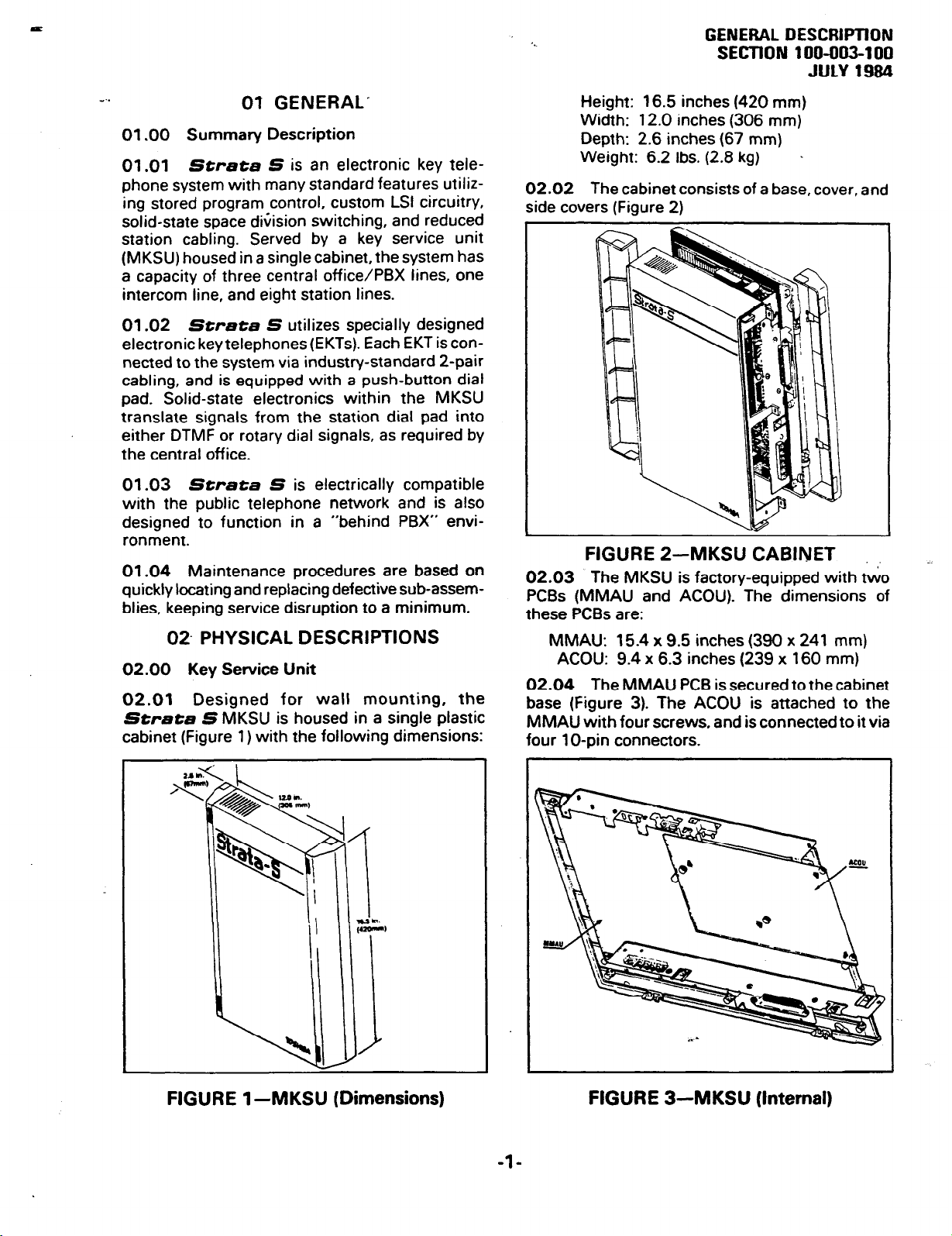
02.02 The cabinet consists of a base, cover. and
side covers (Figure 2)
Height: 16.5 inches (420 mm)
Width: 12.0 inches (306 mm)
Depth: 2.6 inches (67 mm)
Weight: 6.2 Ibs.
(2.8
kg) .
01.03 Strata S is electrically compatible
with the public telephone network and is also
designed to function in a “behind PBX” environment.
01.04 Maintenance procedures are based on
quickly locating and replacing defective sub-assemblies, keeping service disruption to a minimum.
02 PHYSICAL DESCRIPTIONS
02.00 Key Service Unit
02.01 Designed for wall mounting, the
Strata S MKSU is housed in a single plastic
cabinet (Figure 1) with the following dimensions:
I
FIGURE 2-MKSU CABINET
02.03 The MKSU is factory-equipped with two
PCBs (MMAU and ACOU). The dimensions of
these PCBs are:
MMAU: 15.4 x 9.5 inches (390 x 241 mm)
ACOU: 9.4 x 6.3 inches (239 x 160 mm)
02.04
base (Figure 3). The ACOU is attached to the
MMAU with four screws. and is connected to it via
four 1 O-pin connectors.
The MMAU PCB is secured to the cabinet
FIGURE 1 -MKSU (Dimensions)
FIGURE 3-MKSU (Internal)
-l-
Page 6
GENERAL DESCRIPTION
SEGTION 106-003-100
JULY 1984
Speaker
-I
‘.
/
o O.+,,Messege Waiting/
YIR
I
“52
CQ
3
cl
Yo
I
OSb
OS
“- Kers
,.
Flash Key
DND
Kay
I
Programmable
Modluler
Cord
1 O-key l *S’* TVPE EKT
L
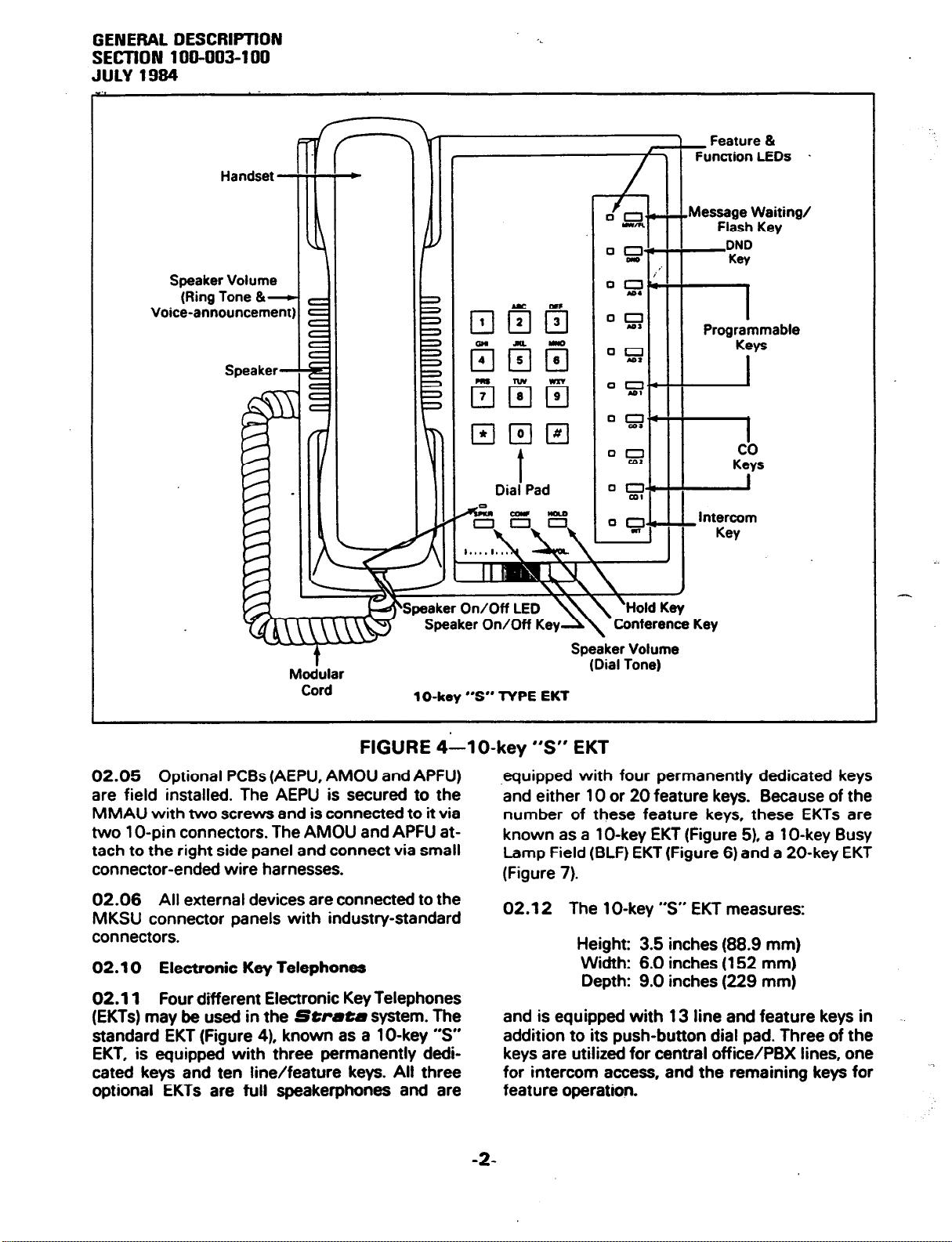
FIGURE 4-l O-key “S” EKT
02.05 Optional PCBs (AEPU, AMOU and APFU)
are field installed. The AEPU is secured to the
MMAU with two screws and is connected to it via
two 1 O-pin connectors. The AMOU and APFU attach to the right side panel and connect via small
connector-ended wire harnesses.
02.06 All external devices are connected to the
MKSU connector panels with industry-standard
connectors.
02.10 Electronic Key Telephones
02.11 Four diierent Electronic Key Telephones
(EKTs) may be used in the
standard EKT (Figure 4), known as a lo-key “S”
EKT, is equipped with three permanently dedi-
cated keys and ten line/feature keys. All three
optional EKTs are full speakerphones and are
Strata
system. The
Speaker Volume
(Dial Tone)
.equipped with four permanently dedicated keys
and either 10 or 20 feature keys. Because of the
number of these feature keys, these EKTs are
known as a lo-key EKT (Figure 5). a lo-key Busy
Lamp Field (BLF) EKT (Figure 6) and a 20-key EKT
(Figure 7).
02.12 The 1 O-key “S” EKT measures:
Height: 3.5 inches (88.9 mm)
Width: 6.0 inches (152 mm)
Depth: 9.0 inches (229 mm)
and is equipped with 13 line and feature keys in
addition to its push-button dial pad. Three of the
keys are utilized for central office/PBX lines, one
for intercom access, and the remaining keys for
feature operation.
-2-
Page 7
Speaker Volume -
Rina Tone 81 Intercom
Voice Level
‘.
Feature &
Function LEDs
GENERAL DESCRlPTlDN
SECTION 100-003-l 00
JULY 1984
!Speaker Volume -
Dial Tone & Voice
/Level
Handset -
Speaker -
/
Modular
Cord
Speaker On/Off LED.
!+eaker On/Off Key
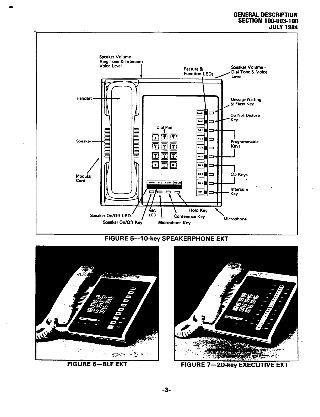
FIGURE
5-lo-key SPEAKERPHONE EKT
/
’ rk
LED
Dial,Pad
Hold Key
\
Conference Key
,& Flash Key
/
I
/KW
.--
.-.--
1
-I .
.--
- Key
\
Microphone
Message Waiting
Do Not Disturb
I
Programmable
Keys
CO Keys
Intercom
.?yJii~$’ - ;rF. ; ‘,
I
:
4’
FIG&E 6-BLF EKT
-3-
Page 8
GENERAL DESCRIPTION
SECTION 100-003-100
JULY 1994
-..
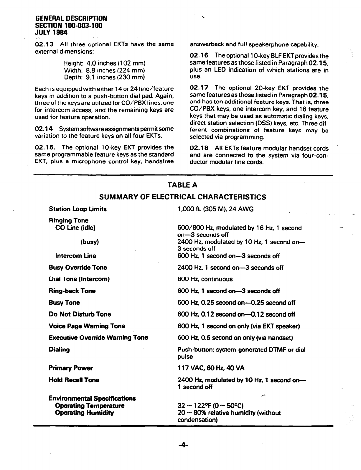
02.13 All three optional EKTs have the same
external dimensions:
Height: 4.0 inches (102 mm)
Width: 8.8 inches (224 mm)
Depth: 9.1 inches (230 mm)
. -
answerback and full speakerphone capability.
02.16 The optional 1 O-key BLF EKT provides the
same features as those listed in Paragraph 02.15,
plus an LED indication of which stations are in
use.
Each is equipped with either 14 or 24 line/feature
keys in addition to a push-button dial pad. Again,
three of the keysare utilized for CO/PBX lines, one
for intercom access, and the remaining keys are
used for feature operation.
02.14 System software assignments permit some
variation to the feature keys on all four EKTs.
02.15. The optional 1 O-key EKT provides the
same programmable feature keys as the standard
EKT, plus a microphone control key, handsfree
TABLE A
SUMMARY OF ELECTRICAL CHARACTERISTICS
Station Loop Limits
Ringing Tone
CO tine (idle)
(busy)
Intercom Line
02.17 The optional 20-key EKT provides the
same features as those listed in Paragraph 02.15,
and has ten additional feature keys. That is, three
CO/PBX keys, one intercom key, and 16 feature
keys that may be used as automatic dialing keys,
direct station selection (DSS) keys, etc. Three different combinations of feature keys may be
selected via programming.
02.18 All EKTs feature modular handset cords
and are connected to the system via four-conductor modular line cords.
1 ,DOD ft. (305 M), 24 AWG
600/800 Hz, modulated by 16 Hz, 1 second
on--3secondsoff
2400 Hz, modulated by 10 Hz, 1 second on3 seconds off
606 Hz, 1 second on-3 seconds off
4
Busy Override Tone
Dial Tone (Intercom)
Ring-back Tone
Busy Tone
Do Not Disturb Tone
Voice Page Warning Tone
Executive Override Warning Tone
Dialing
Primary Power
Hold Recall Tone
Environmental Specifications
Operating Temperature
Operating Humidity
.
2400 Hz, 1 second on-3 seconds off
600 Hz, continuous
600 Hz, 1 second on-3 seconds off
600 Hz, 0.25 second on-O.25 second off
600 Hz, 0.12 second on-O. 12 second off
600 Hz, 1 second on only (via EKT speaker)
600 Hz, 0.5 second on only (via handset)
Push-button; system-generated DTMF or dial
pulse
117VAC,6OHz,4OVA
2400 Hz, modulated by 10 Hz, 1 second on-
1 second off
. . =
32 - 122OF (0 - 50%)
20 - 6096 relative humidity (without
condensation)
Page 9
GENERAL DESCRIPTION
SECTION 100-003-l 00
JULY 1994
-.’ 03 ELECTRIC/ii CHARACTERISTICS
03.01 The electrical characteristics of the systern are detailed in Table A.
03.02 The MKSU operates from an external 24
VDC power supply.
03.03 Loss of AC power will cause operational
failure of the system. System memory, however, is
STANDARD FEATURES
l
All Call Voice Page
l
Alternate Point Answer
l
Automatic Dialing-System
l
Automatic Hold Recall
l
Automatic Privacy -
l
Automatic Release from Hold
l
Busy Override
l
Conference-Multi-station (non-amplified)
l
Conference-Multi-trunk (non-amplified)
l
Distinctive Ringing
l
DTMF and Dial Pulse Compatible
l
External Page Interface
l
Flash Key (PBX Transfer or CO Dial Tone
Recall)
protected from loss due to power failure with a
memory back-up battery. Full system reserve
power is available as an option.
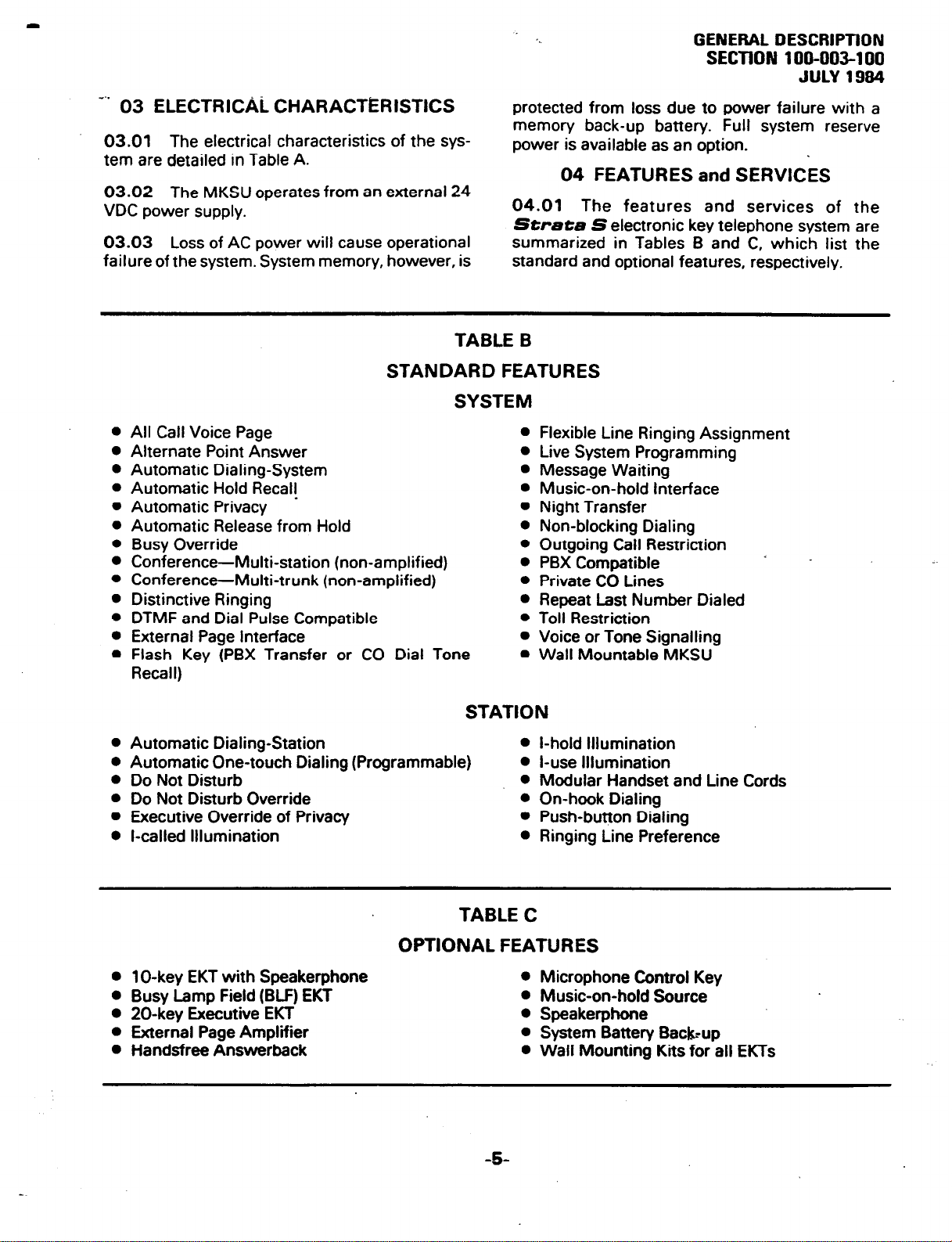
04.01 The features and services of the
Strata S electronic key telephone system are
summarized in Tables B and C, which list the
standard and optional features, respectively.
TABLE B
SYSTEM
l
l
l
l
l
l
l
l
l
l
l
l
l
04 FEATURES and SERVICES
Flexible Line Ringing Assignment
Live System Programming
Message Waiting
Music-on-hold Interface
Night Transfer
Non-blocking Dialing
Outgoing Call Restriction
PBX Compatible
Private CO Lines
Repeat Last Number Dialed
Toll Restriction
Voice or Tone Signalling
Wall Mountable MKSU
l
Automatic Dialing-Station
l
Automatic One-touch Dialing (Programmable)
l
Do Not Disturb
l
Do Not Disturb Override
l
Executive Override of Privacy
l
l-called Illumination
OPTIONAL FEATURES
0 1 O-key EKT with
l
Busy Lamp Field
l
20-key
l
External Page Amplifier
l
Handsfree Answerback
Executive EKT
Speakerphone
(BLF) EKT
STATION
l
l
l
l
l
l
TABLE C
l
l
l
l
l
-5
i-hold Illumination
l-use Illumination
Modular Handset and Line Cords
On-hook Dialing
Push-button Dialing
Ringing Line Preference
Microphone
Music-on-hold
Control Key
Source
Speakerphone
System Battery Baaup
Wall
Mounting Kits for all EKTs
Page 10
GENERAL DESCRIPTION
SECTION 100-003-l 00
AJLY 1984
M..
05 SYSTEii OPERATIO’N
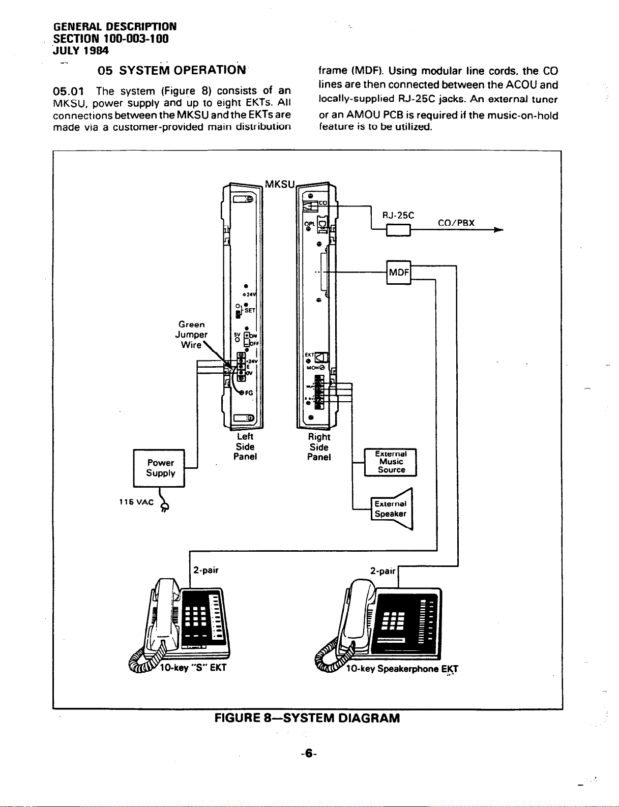
05.01 The system (Figure 8) consists of an
MKSU, power supply and up to eight EKTs. All
connections between the MKSU and the EKTs are
made via a customer-provided main distribution
MKSU MKSU
frame (MDF). Using modular line cords, the CO
lines are then connected between the ACOU and
locally-supplied RJ-25C jacks. An external tuner
or an AMOU PCB is required if the music-on-hold
feature is to be utilized.
5 VAC
Side
Panel
b
f External 1
2-pair
n +
FIGURE 8-SYSTEM DIAGRAM
-6-
Page 11
E
‘.
GENERAL DESCRIPTION
SECTION 100-003-l 00
JULY 1994
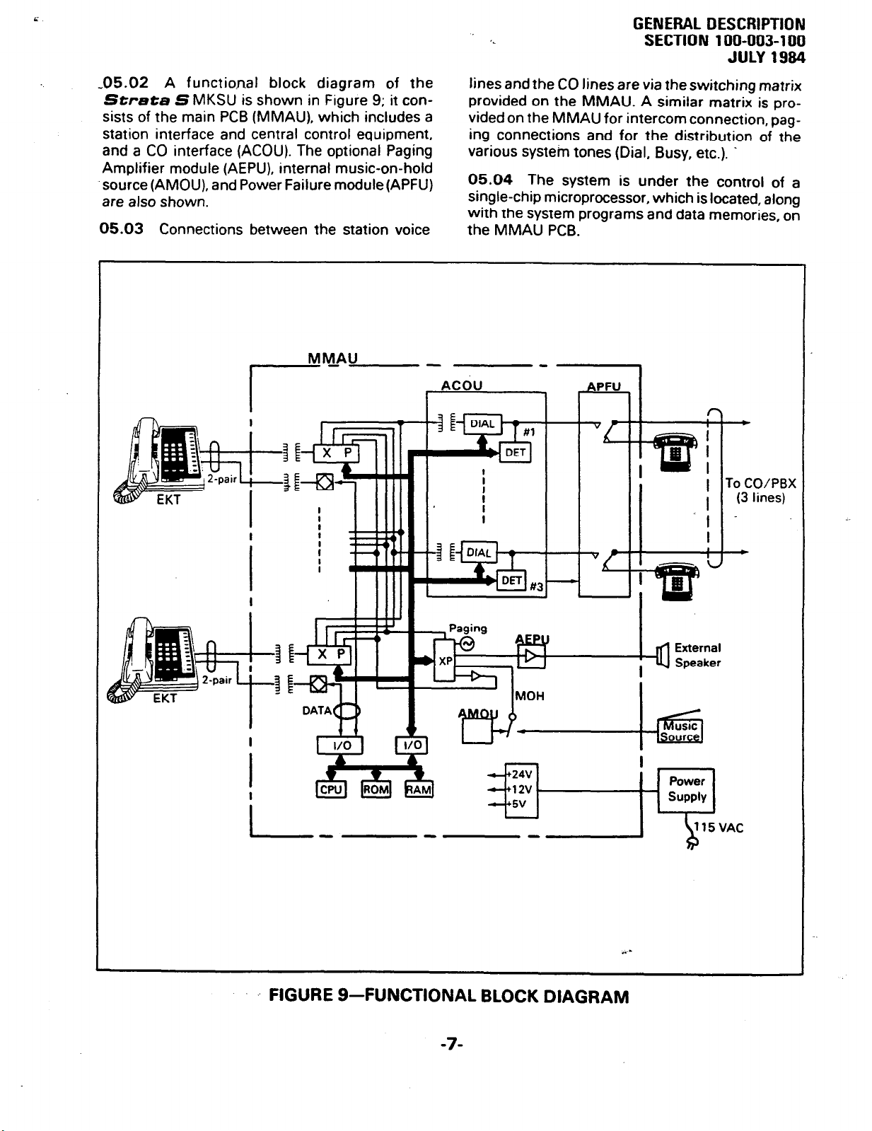
-05.02 A functio.nal block diagram of the
Strata S MKSU is shown in Figure 9; it con-
sists of the main PCB (MMAU), which includes a
station interface and central control equipment,
and a CO interface (ACOU). The optional Paging
Amplifier module (AEPU), internal music-on-hold
.source (AMOU), and Power Failure module(APFU)
are also shown.
05.03 Connections between the station voice
MM-AU
I---- -ncou - --z-I
lines and the CO lines are via theswitching matrix
provided on the MMAU. A similar matrix is provided on the MMAU for intercom connection, pag-
ing connections and for the distribution of the
various system tones (Dial, Busy, etc.). .
05.04 The system is under the control of a
single-chip microprocessor, which is located, along
with the system programs and data memories, on
the MMAU PCB.
-
To
CO/PBX
1 (3 lines)
I
DATA
-
115VAC
b
. . -
FIGURE 9-FUNCTIONAL BLOCK DIAGRAM
-7-
Page 12
GENERAL DESCRIPTION
SECTION 100-003-l 00
JULY 1984
e..
06 SYSTEM CONFIGURATION
06.00 Key Service Unit
06.01 Completewith all options, the MKSU util-
izes five circuit boards. The names and functions
of the PCBs are:
AMOU:
An optional music-on-hold source.
APFU:
An optional power failure transfer module
used to transfer the CO lines to single line
telephones in the event of a power failure.
ACOU (MF or DP):
An interface between the MKSU and the pub-
lic telephone network or PBX lines. Ring detection, hold and dial outpulsing for three circuits
are performed by this PCB. Depending upon
local CO requirements, an MF or DP type of
ACOU will be provided (MF for DTMF outpuls-
ing; DP for rotary dial outpulsing).
MMAU:
The main PCB of the MSKU, consists of the
following four functions:
a) Station Interface-An interface between
the MKSU and EKTs, which includes the
solid-state space division matrix used for
voice connections between the EKTs .and
the CO/PBX lines. Two-pair wiring is
required for each EKT; one pair carrying
voice and the other pair carrying data to
and from the EKT.
b) Control-All system control functions are
performed by the single-chip micro-processor. The system program stored in
ROM, the RAM for system operations, and
the RAM for system data storage are also
located on this circuit board.
c) Tone-Performs a number of miscel-
laneous system functions:
l
Generates system tones.
0 Provides the switching matrix for the
delivery of tones for both paging and
intercom connections.
l
Houses the interface for the external
paw.
l
Houses the interface for music-on-hold.
d) Power Regulating-Performs the following:
l
Provides connection points for the 24
VDC input power.
l
Houses the voltage regulators that pro-
vide 12 and 5 VDC for system operation.
l
Houses a circuit breaker that protects
the 24 VDC, EKT, and MKSU circuits.
AEPU:
An optional 3-watt amplifier for external paging.
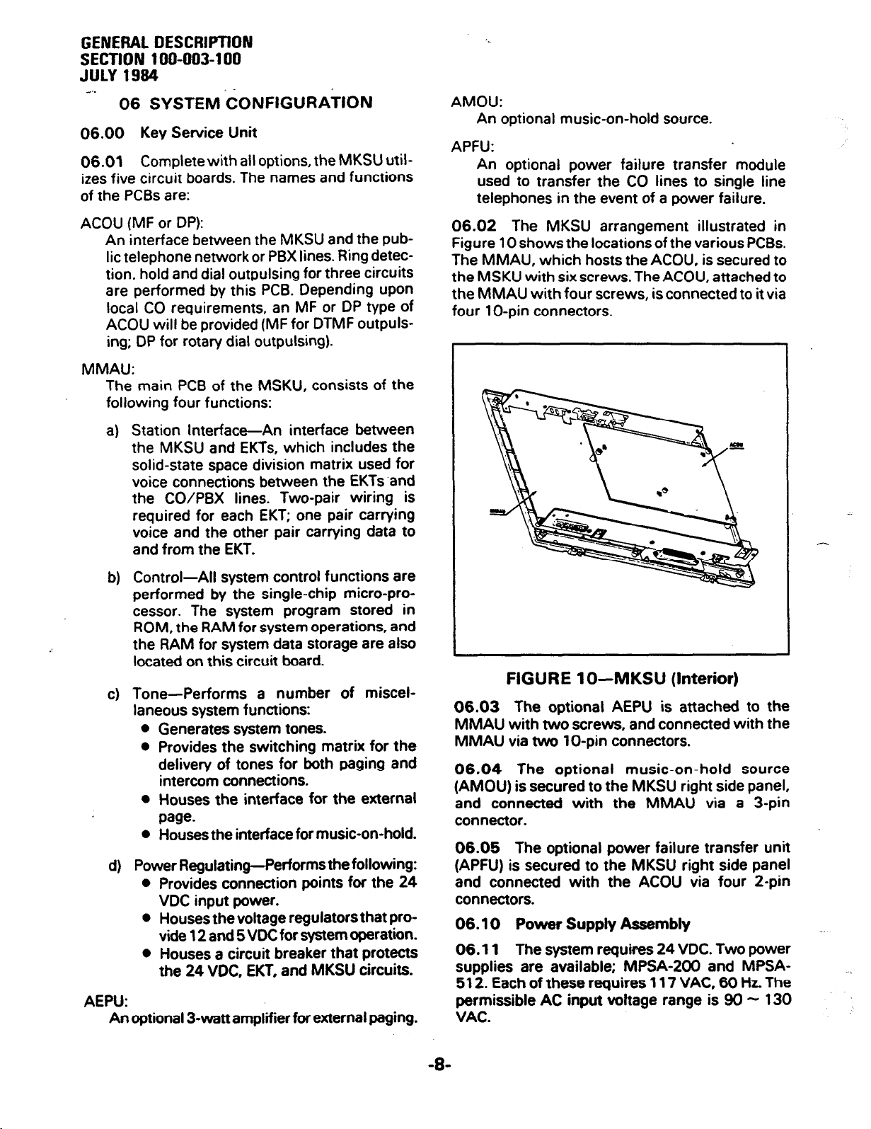
06.02 The MKSU arrangement illustrated in
Figure 10 shows the locations of the various PCBs.
The MMAU, which hosts the ACOU, is secured to
the MSKU with six screws. The ACOU, attached to
the MMAU with four screws, is connected to it via
four 1 O-pin connectors.
FIGURE lo-MKSU (Interior)
06.03 The optional AEPU is attached to the
MMAU with two screws, and connected with the
MMAU via two lo-pin connectors.
06.04 The optional music-on-hold source
(AMOU) is secured to the MKSU right side panel,
and connected with the MMAU via a 3-pin
connector.
06.05 The optional power failure transfer unit
(APFU) is secured to the MKSU right side panel
and connected with the ACOU via four 2-pin
connectors.
06.10 Power Supply Assembly
06.11 The system requires 24 VDC. Two power
supplies are available; MPSA-200 and MPSA-
512. Each of these requires 117 VAC, 60 Hz. The
permissible AC input voltage range is 90 - 130
VAC.
Page 13

GENERAL DESCRIPTION
SECTlON 100-003-l 00
JULY 1994
-..06.12 An optional battery back-up unit (PBBU)
is available for the MPSA-200. With the optional
battery back-up assembly installed, all functions of
the Strata S system. will continue to operate
for several hours (the actual time period is in direct
ratio to the type and size of batteries selected) after
a loss of normal electrical power. No calls will be
disconnected during switch-over to battery power.
1 O-key 1 O-key
#l
#2
20-key 20-key 20-key
#I #2 #3
FIGURE 1 l-l O-key “S” EKT
06.20 Station Equipment
06.21
“S” electronic key telephone (Figure 11) are:
handset, dial pad, speaker, sliding ringing/speaker
volume control, 3-position volume control, one
intercom key, three CO/PBX line keys and nine
feature keys. LED indicators are provided for all
keys except FOLD] and [m%] keys. With the
exception of the three permanently dedicated
keys, the feature keys can be assigned to one of
two modes by programming (see Figure 12).
06.22 Standard features of the 1 O-key “S” EKT
include, among other standard features, paging,
one-touch automatic dialing keys,
In initialized mode, three of the keys are utilized for
CO/PBX lines, one for intercom
for
Do Not Disturb and Message Waiting/Flash.
The principal components of the lo-key
_- -.
and auto-redial.
access, four keys
one-touch automatic dialing and one each for
FIGURE 12-KEY LAYOUT
06.23 The optional lo-key EKT (Figure 13) provides the same programmable feature keys as the
standard EKT. plus a microphone control keym,
handsfree answerback and full speakerphone
capability.
I
FIGURE 13-l O-key EKT
I
-S-
Page 14
GENEML DESCRlPTlDN
SECTION 100-003-l 00
aJ~lY 1994 _ _
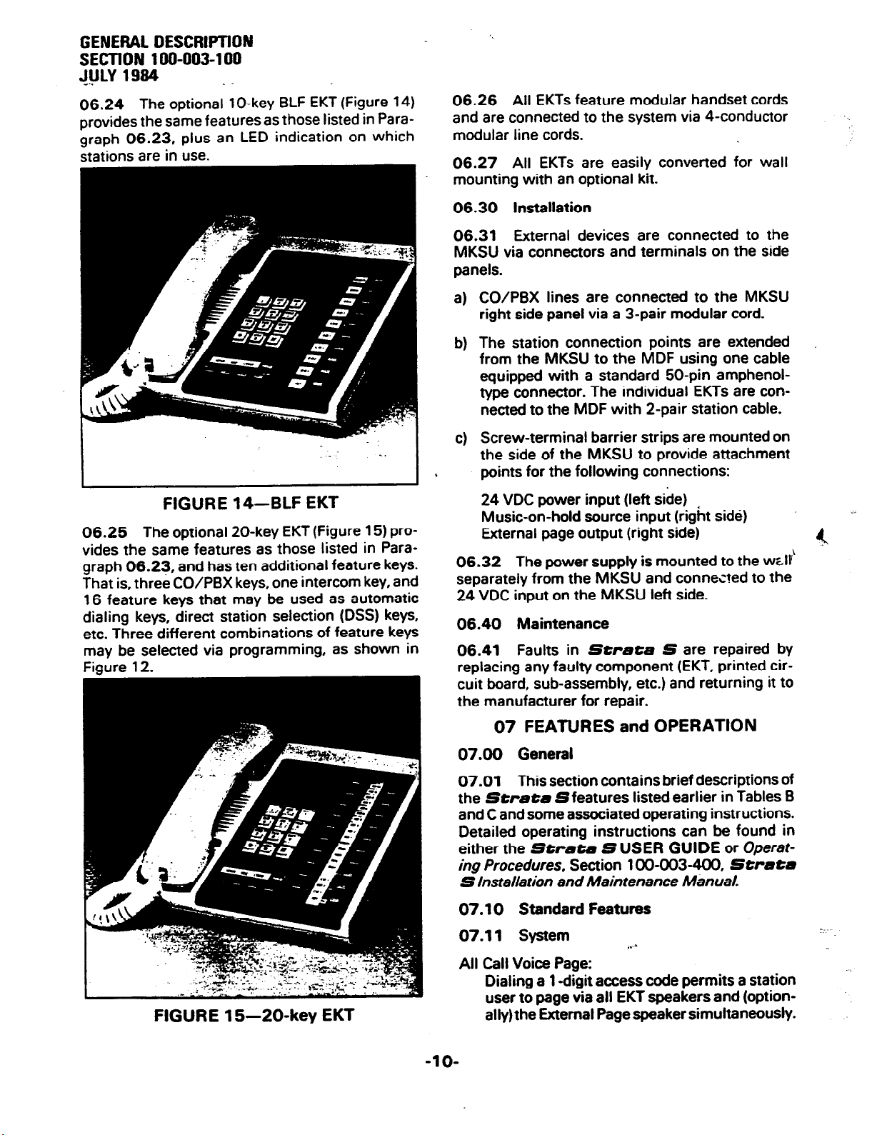
06.24 The optional lo-key BLF EKT (Figure 14)
provides the same features as those listed in Paragraph 06.23, plus an LED indication on which
stations are in use.
- :
. .
I
FIGURE 14--BLF EKT
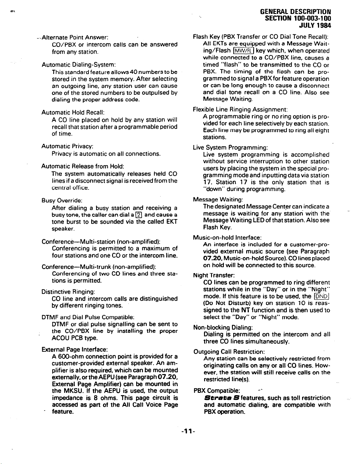
06.25 The optional 20-key EKT (Figure 15) provides the same features as those listed in Para-
graph 06.23, and has ten additional feature keys.
That is, three CO/PBX keys, one intercom key, and
16 feature keys that may be used as automatic
dialing keys, direct station selection (DSS) keys,
etc. Three different combinations of feature keys
may be selected via programming, as shown in
Fiaure 12.
06.26 All EKTs feature modular handset cords
and are connected to the system via 4-conductor
modular line cords.
06.27 All EKTs are easily converted for wall
mounting with an optional kit.
06.30 Installation
06.31 External devices are connected to the
MKSU via connectors and terminals on the side
panels.
CO/PBX lines are connected to the MKSU
a)
right side panel via a 3-pair modular cord.
The station connection points are extended
b)
from the MKSU to the MDF using one cable
equipped with a standard 50-pin amphenoltype connector. The individual EKTs are connected to the MDF with 2-pair station cable.
Screw-terminal barrier strips are mounted on
cl
the side of the MKSU to provide attachment
points for the following connections:
24 VDC power input (left side)
Music-on-hold source input (right side)
External page output (right side)
06.32
separately from the MKSU and connected to the
24 VDC input on the MKSU left side.
06.40 Maintenance
06.41 Faults in Strata S are repaired by
replacing any faulty component (EKT, printed circuit board, sub-assembly, etc.) and returning it to
the manufacturer for repair.
The power supply is mounted to the well’
. .
-.
?4
FIGURE 15-20-key EKT
07 FEATURES and OPERATION
07.00
07.01 This section contains brief descriptions of
the
and C and some associated operating instructions.
Detailed operating instructions can be found in
either the Strata S USER GUIDE or Operating Procedures. Section 100-003-4C0,
S Jnstallation and Maintenance Manual.
General
Strata
Sfeatures listed earlier in Tables B
07.10 Standard Features
07.11 System
All Call Voice Page:
Dialing a 1 -digit access code permits a station
user to page via all EKT speakers and (optionally)the External Page speaker simultaneously.
-1 o-
Strata
Page 15
GENERAL DESCRIPTION
SECTION 100-003-100
JULY 1984
--.Alternate Point Answer:
CO/PBX or intercom calls can be answered
from any station.
Automatic Dialing-System:
This standard feature allows 40 numbers to be
stored in the system memory. After selecting
an outgoing line, any station user can cause
one of the stored numbers to be outpulsed by
dialing the proper address code.
Automatic Hold Recall:
A CO line placed on hold by any station will
recall that station after a programmable period
of time.
Automatic Privacy:
Privacy is automatic on all connections.
Automatic Release from Hold:
The system automatically releases held CO
lines if a disconnect signal is received from the
central off ice.
Busy Override:
After dialing a busy station and receiving a
busy tone, the caller can dial a q and cause a
tone burst to be sounded via the called EKT
speaker.
Conference-Multi-station (non-amplified):
Conferencing is permitted to a maximum of
four stations and one CO or the intercom line.
Conference-Multi-trunk (non-amplified):
Conferencing of two CO lines and three sta-
tions is permitted.
Distinctive Ringing:
CO line and intercom calls are distinguished
by different ringing tones.
DTMF and Dial Pulse Compatible:
DTMF or dial pulse signalling can be sent to
the CO/PBX line by installing the proper
ACOU PCB type.
External Page Interface:
A 6OD-ohm connection point is provided for a
customer-provided external speaker. An amplifier is also required, which can be mounted
externally, or the AEPU (see Paragraph 07.20,
External Page Amplifier) can be mounted in
the MKSU. If the AEPU is used, the output
impedance is 8 ohms. This page circuit is
accessed as part of the All Call Voice Page
- feature.
Flash Key (PSX Transfer or CO Dial Tone Recall):
All EKTs are equipped with a Message Wait-
ing/Flash m) key which, when operated
while connected to a CO/PBX line, causes a
timed “flash” to be transmitted to the CO or
PBX. The timing of the flash can be programmed to signal a PBX for feature operation
or can be long enough to cause a disconnect
and dial tone recall on a CO line. Also see
Message Waiting.
Flexible Line Ringing Assignment:
A programmable ring or no ring option is pro-
vided for each line selectively by each station.
Each line may be programmed to ring all eight
stations.
Live System Programming:
Live system programming is accomplished
without service interruption to other station
users by placing the system in the special pro-
gramming mode and inputting data via station
17. Station 17 is the only station that is
“down” during programming.
Message Waiting:
The designated Message Cent‘er can indicate a
message is waiting for any station with the
Message Waiting LED of that station. Also see
Flash Key.
Music-on-hold Interface:
An interface is included for a customer-provided external music source (see Paragraph
07.20, Music-on-hold Source). CO lines placed
on hold will be connected to this source.
Night Transfer:
CO lines can be programmed to ring different
stations while in the “Day” or in the “Night”
mode. If this feature is to be used, the w
(Do Not Disturb) key on station 10 is reas-
signed to the NT function and is then used to
select the “Day” or “Night” mode.
Non-blocking Dialing:
Dialing is permitted on the intercom and all
three CO lines simultaneously.
Outgoing Call Restriction:
Any station can be selectively restricted from
originating calls on any or all CO lines. How-
ever, the station will still receive calls on the
restricted line(s).
PBX Compatible: +a-
Strutu
and automatic dialing, are compatible with
PBX operation.
Sfeatures, such as toll restriction
-ll-
Page 16
GENERAL OESCRlWlON
SECTION 100-003-l 00
JULY 1984
e..
- Private CO Lines:
Restrictions may be programmed into the sys-
tem so that selected CO line(s) may appear
only on selected station(s).
Do Not Disturb Override (Programmable Option):
After reaching a DND station, that station may
be advised that a call is waiting by dialing q . A
tone signal will be heard at the DND station.
Repeat Last Number Dialed:
The last number dialed by each station is
always stored by the system and will be dialed
automatically whenever the station user selects
an outgoing line and depresses the q key.
Toll Restriction:
Selectively programmed on a per-station, per-
line basis.
tion by rejecting the numbersa andm as the
first or second digit and limiting the total
number of digits dialed to seven or eight.
Voice or Tone Signalling:
A programmable system feature that option-
ally selects either tone ringing or voice page as
the primary method of intercom call signalling.
The calling station, however, may choose the
alternate method by dialing a following the
station number.
Wall Mountable MKSU:
The MKSU is designed for wall mounting only.
07.12 Station
Automatic Dialing-Station:
Each EKT can store a private list of ten fre-
quently used telephone numbers.
Automatic One-touch Dialing (Programmable):
This feature can be used with an EKT that
includes m keys in its programmed as-
signments.
a) A station number can be stored at each
m key.
b) A number stored in the memory can be
sent over a CO line by depressing the
appropriate a key after accessing the
CO line.
NOTE:
Each a key is counted as one of the 10
possible stored numbers available to each
station.
Do Not Disturb:
This feature is activated and deactiited by
alternate depressions of the m key. A sta-
tion calling a station that is in the DND mode
will receive a fast busy tone.
Strata S
performs toll restric-
Executive Override of Privacy:
A station that is programmed for this feature
will override the automatic privacy feature and
enter any existing conversation within the system. A warning tone, however, is inserted
before the overriding station is actually con-
nected. A maximum of two stations can be
programmed for executive override.
l-called Illumination:
A distinctive flash appears on the intercom
LED at the EKT that is actually being called.
l-hold Illumination:
The EKT user is shown a distinctive LED flash
to indicate a line actually placed on hold at that
EKT. All other stations see the usual on-hold
flash.
l-use Illumination:
A distinctive flash rate shows the line presently in use at a given EKT. Other stations see
a steadily illuminated LED for that line.
Modular Handset and Line Cords:
All EKTs are equipped with modular handset
and line cords.
On-hook Dialing:
Strata S
handset still on-hook. Call progress can be
heard via the telephone speaker; no need to
pick up the handset until your party answers.
Push-button Dialing:
All
Streta
button dial pads.
Ringing Line Preference:
A line ringing at a station can be answered by
merely lifting the handset or depressing the
m key (optional speakerphone EKTs only).
The ringing line will be automatically selected.
07.20 Optional Features
1 D-key EKT with Speakerphone:
An optional EKT provides handsfree answerback and full speakerphone capability.
Busy Lamp Field (BLF) El&
An optional lD-key EKT provides handsfree
answerback, full speakerphone capability, and
an LED panel showing the busy/idle
lets you dial your calls with the
SEKTs are equipped with push-
status
of
-12-
Page 17
f
a-
GENERAL DESCRIPTION
SECTION 100-003-l 00
JULY 1994
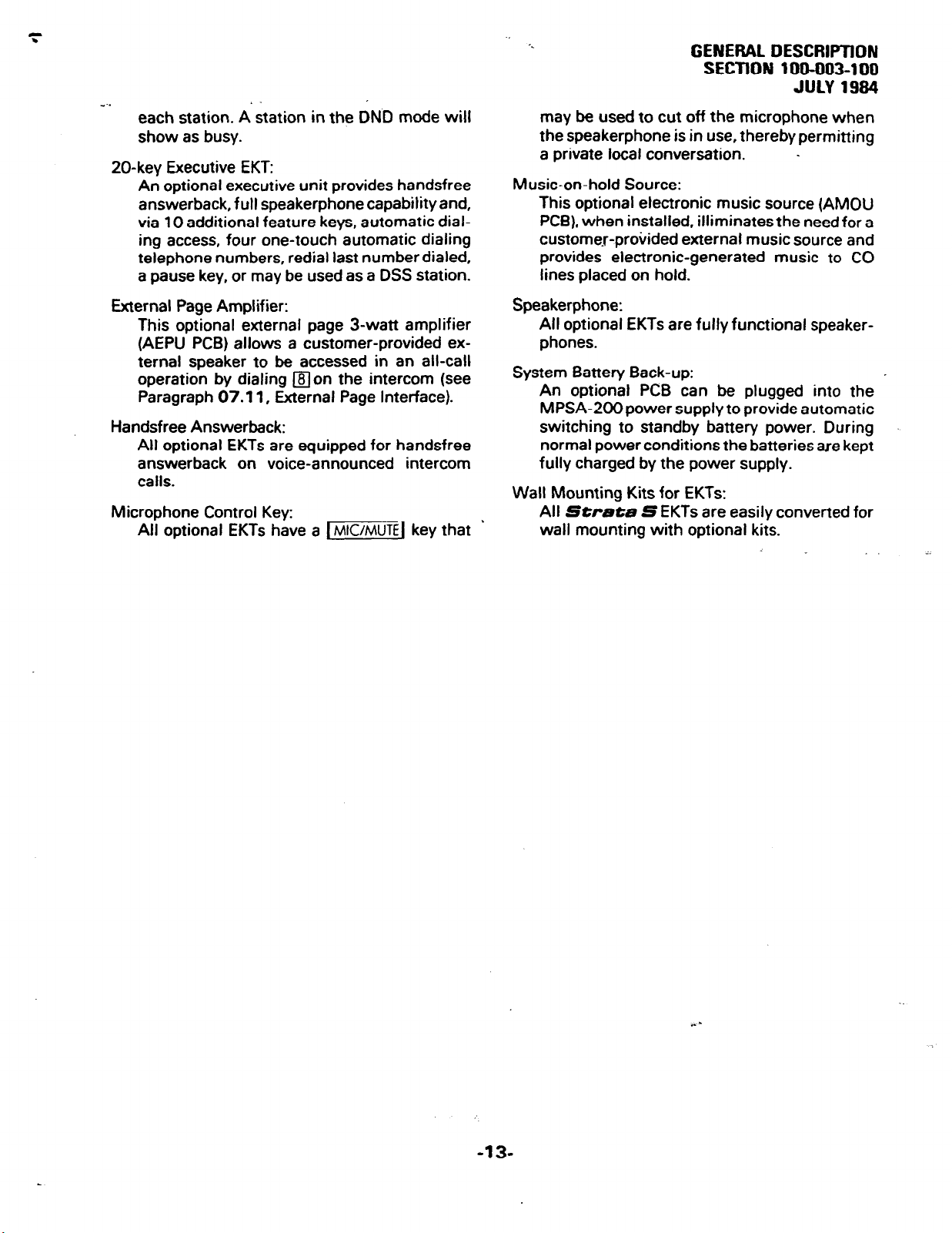
each station. A station in the DND mode will
show as busy.
ZO-key Executive EKT:
An optional executive unit provides handsfree
answerback, full speakerphone capability and,
via 10 additional feature keys, automatic dial-
ing access, four one-touch automatic dialing
telephone numbers, redial last number dialed,
a pause key, or may be used as a DSS station.
External Page Amplifier:
This optional external page 3-watt amplifier
(AEPU PCB) allows a customer-provided external speaker to be accessed in an all-call
operation by dialing non the intercom (see
Paragraph 07.11, External Page Interface).
Handsfree Answerback:
All optional EKTs are equipped for handsfree
answerback on voice-announced intercom
calls.
Microphone Control Key:
All optional EKTs have a 1-1 key that ’
may be used to cut off the microphone when
the speakerphone is in use, thereby permitting
a private local conversation. _
Music-on-hold Source:
This optional electronic music source (AMOU
PCB), when installed. illiminates the need for a
custome.r-provided external music source and
provides electronic-generated music to CO
lines placed on hold.
Speakerphone:
All optional EKTs are fully functional speaker-
phones.
System Battery Back-up:
An optional PCB can be plugged into the
MPSA-200 power supply to provide automatic
switching to standby battery power. During
normal power conditions the batteries are kept
fully charged by the power supply.
Wall Mounting Kits for EKTs:
All Strata S EKTs are easily converted for
wall mounting with optional kits.
-13-
,. -
Page 18
-
TOSHIBA SYSTEM PRACTICES
ELECTRONIC KEY TELEPHONE SYSTEM
SECTION 100-003-200
INSTALLATION
JULY 1984
,
StrataS --.
INSTALLATION INSTRUCTIONS
Page 19

TOSHIBA SYSTEM PRACTICES
ELECTRONIC KEY TELEPHONE SYSTEM
_..
INSTALLATION
SECTION 100-003-200
JULY 1984
Strata S
INSTALLATION INSTRUCTIONS
TABLE of CONTENTS
PARAGRAPH
01
02
02.00
03
03.00
03.10
03.20
03.30
04
04.00
05
o:.:o
06.10
07
07.00
07.10
07.20
07.30
07.40
08
08.00
08.10
09
09.00
09.10
09.20
09.30
10
10.00
10.10
10.20
10.30
10.40
11
11.10
12
12.00
12.10
12.20
13
13.00
13.10
13.20
13.30
13.40
13.50
SUBJECT
TABLE of CONTENTS ............................
ILLUSTRATION LIST
GENERAL . .... . ..I :: : : : ::: : :: ::: : ::: ::: : ::
PACKING
Inspection
MKSU LOCATlON’REdlJiREMENTS’ : : : : : : : : : : : : : : : : : : : : : :
Power Requirements ..........................
Ventilation Requirements ........................
Environment Factors ..........................
Cabling Considerations .........................
MKSU MOUNTING
Wall Mounting theMKSU ’ : : : : : : : : : : : : : 1 : : : : : : : : : :
PRINTED CIRCUIT BOARD DESCRIPTIONS
OPTION SELECTION .......... : : : : : : : : : : : : : : : : : :
External Page Option Selection ......................
Music-on-hold Option Selection
PCBINSTALLATION
General Information ...........................
AMOU (MOH Source) Installation ................ ) ...
APFU (Power Failure Transfer Unit) Installation ............ : :
AEPU (External Page Unit) Installation ...................
MKSU Cover Installation .........................
POWER CONNECTION ...........................
Cable Connection ............................
Test Procedure
CABLECONNECTIONS - : : : : : : : : : : : : : : : : : : : : : : : : : : :
MDF Configuration ............................
Station Cable Connection ........................
Intercom Code Assignment ........................
CO Line Connection ...........................
EKT INFORMATION .............................
General
lo-key S EKT Wall Mounting .......................
Optional EKT Wall Mounting .......................
Installing the Handset Hanger Kit .....................
EKT Connections
SYSTEM POWER-UP INITIAL& . : : : : : : : : : : : : : : : : : : : : : : :
Clearing Automatic Dialing ........................
SYSTEM TEST PROCEDURES
lo-keys EKTFunctional Check’ : : : : : : : : : : : : : : : : : : : : : :
Optional EKT Functional Check ......................
Feature Check
MISCELLANEOUS EQljlPMENT%NhiECTiONS ’ : : : : : : : : : : : :- : : : :
Wiring Connections ...........................
Music-on-hold Source ..........................
External Paging Connections .......................
Direct External Speaker Connection ....................
External Amplifier Connection
PowerFailureTransfer
.................................
....... . . . . . . . . . . . . . . . . . . . . .
................................
se-
. ..::::::::::::::::::::::
PAGE
i
ii
1
1
1
1
1
1
1 ’
1
1
1
2
2
2
3
3
3
3
.
4’
4
5
5
5
5
6
6
7
7
7
7
7
10
10
11
12
12
12
13
13
14
15
15
15
15
15
15 -.
17
17
Page 20
TOSHIBA SYSTEM PRACTICES
ELECTRONIC KEY TELEPHONE SYSTEM
w..
INSTALLATION
SECTION 100-003-200
JULY 1984
Strata S
INSTALLATION INSTRUCTIONS
ILLUSTRATION LIST
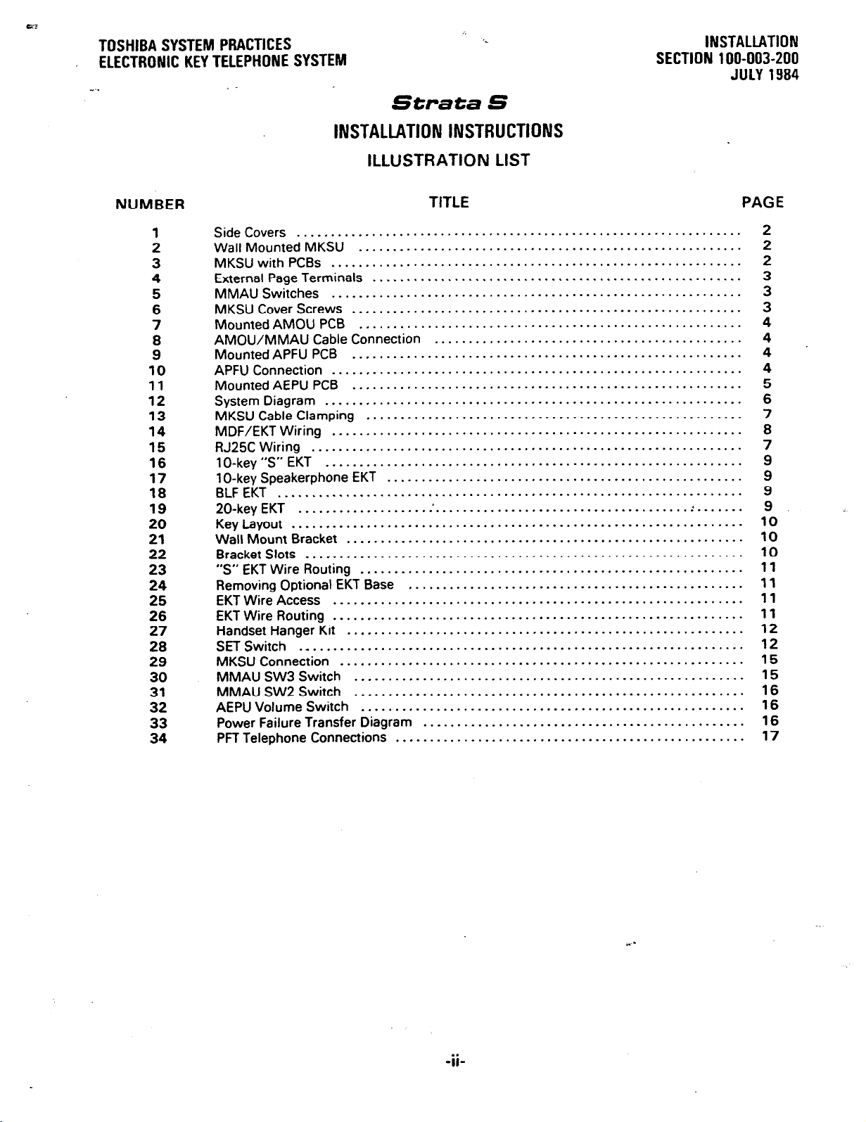
NUMBER
1
2
3
4
5
6
7
8
9
10
11
12
13
14
15
16
17
18
19
20
21
22
23
24
25
26
27
28
29
30
::
33
34
TITLE PAGE
SideCovers .................................................................
WallMountedMKSU ........................................................
MKSUwith PCBs ............................................................
External Pagelerminals ......................................................
MMAUSwitches ............................................................
MKSUCoverScrews .........................................................
MountedAMOUPCB
AMOU/MMAU Cable Connection
MountedAPFUPCB .........................................................
APFU Connection
Mounted AEPU PCB
System Diagram
MKSU Cable Clamping
MDF/EKT Wiring
RJ25C Wiring
1 D-key “S” EKT
1 O-key Speakerphone EKT
BLFEKT
20-key EKT
KeyLayout
Wall Mount Bracket
BracketSlots ................................................................
“S” EKT Wire Routing
Removing Optional EKT Base .................................................
EKT Wire Access
EKT Wire Routing
Handset Hanger Kit
SET Switch .
MKSU Connection
MMAU SW3 Switch
MMAU SW2 Switch
AEPU Volume Switch
Power Failure Transfer Diagram
PFf Telephone Connections
...............................................................
....................................................................
.........................................................
..................................................................
...............................................................
_
........................................................
............................................. 4
............................................................
......................................................... 5
.............................................................
.......................................................
............................................................ 8
............................................................. 9
....................................................
..........................................................
........................................................
............................................................
............................................................
..........................................................
...........................................................
.........................................................
.........................................................
........................................................
............................................... 16
...................................................
2
2
2
3
3
3
4
4
4
6
7
7
9
9
. ....... 9
10
10
10
11
11
11
11
12
12
15
15
16
16
17
-ii-
Page 21
--.
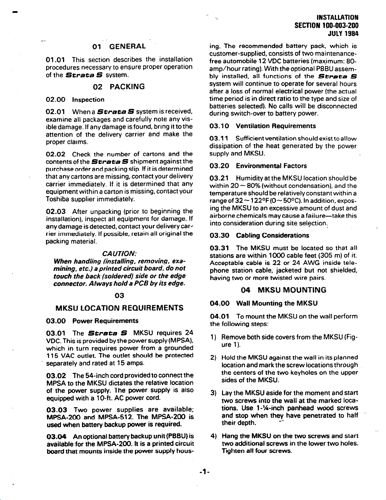
01. GENERAL I
01.01
procedures necessary to ensure proper operation
of the
This section describes the installation
Strata S
system.
02 PACKING
02.00 Inspection
02.01
examine all packages and carefully note any vis-
ible damage. If any damage is found, bring it to the
attention of the delivery carrier and make the
proper claims.
02.02 Check the number of cartons and the
contents of the Strata S shipment against the
purchase order and packing slip. If it is determined
that any cartons are missing, contact your delivery
carrier immediately. If it is determined that any
equipment within a carton is missing, contact your
Toshiba supplier immediately.
02.03 After unpacking (prior to beginning the
installation), inspect all equipment for damage. If
any damage isdetected, contact your delivery card
rier immediately. If possible, retain all original the
packing material.
When a Strata S system is received,
CAUTION:
When handling (installing, removing, examining, etc.) a printed circuit board. do not
touch the back (soldered) side or the edge
connector. Always hold a PCB by its edge.
03
MKSU LOCATION REQUIREMENTS
03.00 Power Requirements
03.01
VDC. This is provided by the power supply (MPSA),
which in turn requires power from a grounded
115 VAC outlet. The outlet should be protected
1 separately and rated at 15 amps.
03.02 The 54-inch cord provided to connect the
MPSA to the MKSU dictates the relative location
of the power supply. The power supply is also
equipped
03.03 Two power supplies are available;
MPSA-200 and MPSA-512. The MESA-200 is
used when battery backup power is required.
The Strata S MKSU requires 24
with a 10-h. AC power cord.
INSTAUATION
SECTION 100-003-200
JULY 1994
ing. The recommended battery pack, which is
customer-supplied, consists of two maintenancefree automobile 12 VDC batteries (maximum: 80amp/hour rating). With the optional PBBU assembly installed, all functions of the Strata S
system will continue to operate for several hours
after a loss of normal electrical power (the actual
time period is in direct ratio to the type and size of
batteries selected). No calls will be disconnected
during switch-over to battery power.
03.10 Ventilation Requirements
03.11 Sufficient ventilation should exist to allow
dissipation of the -heat generated by the power
supply and MKSU.
03.20 Environmental Factors
03.21
within 20 - 80% (without condensation), and the
temperature should be relatively constant within a
range of 32 - 122OF(O- 5OOC). In addition, expos-
ing the MKSU to an excessive amount of dust and
airborne chemicals may cause a failure-take this
into consideration during site selection.
Humidity at the MKSU location should be
03.30 Cabling Considerations
03.31
stations are within loo0 cable feet (305 m) of it.
Acceptable cable
phone station
having two or more twisted wire pairs.
The MKSU must be located so that all
is
22 or 24 AWG inside tele-
cable, jacketed but
not shielded,
04 MKSU MOUNTING
04.00 Wall Mounting the MKSU
04.01
the following steps:
1)
2)
3)
To mount the MKSU on the wall perform
Remove both side covers from the MKSU (Figure 1).
Hold the MKSU against the wall in its planned
location and mark the screw locations through
the centers of the two keyholes on the upper
sides of the MKSU.
Lay the MKSU aside for the moment and start
two screws into the wall at the marked
loca-
tions. Use l-W-inch panhead wood screws
and stop when they have penetrated to half -.
their depth. c*
03.04 An optional battery backup unit (PBBU) is
available for the MPSA-200. It is a printed circuit
board that mounts inside the power supply hous-
-l-
Hang the MKSU on the two screws and start
4)
two additional screws in the lower two holes.
Tghten all four screws.
Page 22
INSTALLATION
SECTION
100-003-200
JULY 1994
‘.
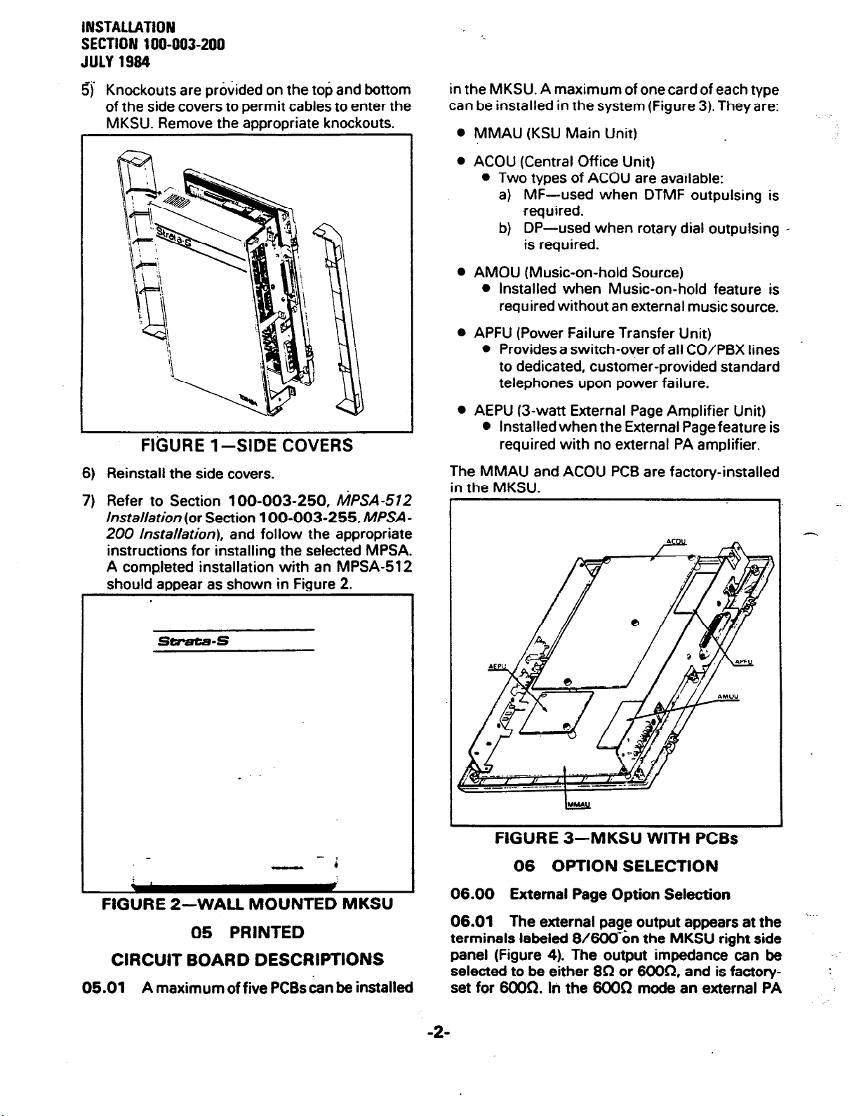
5) Knockouts are provided on the top and bottom
of the side covers to permit cables to enter the
MKSU. Remove the appropriate knockouts.
FIGURE 1 -SIDE COVERS
6) Reinstall the side covers.
7) Refer to Section 100-003-250,
Installation
200 installation),
(or Section 100-003-255,
and follow the appropriate
instructions for installing the selected MPSA.
A completed installation with an MPSA-512
should aooear as shown in Fiaure 2.
MPSA-512
MPSA-
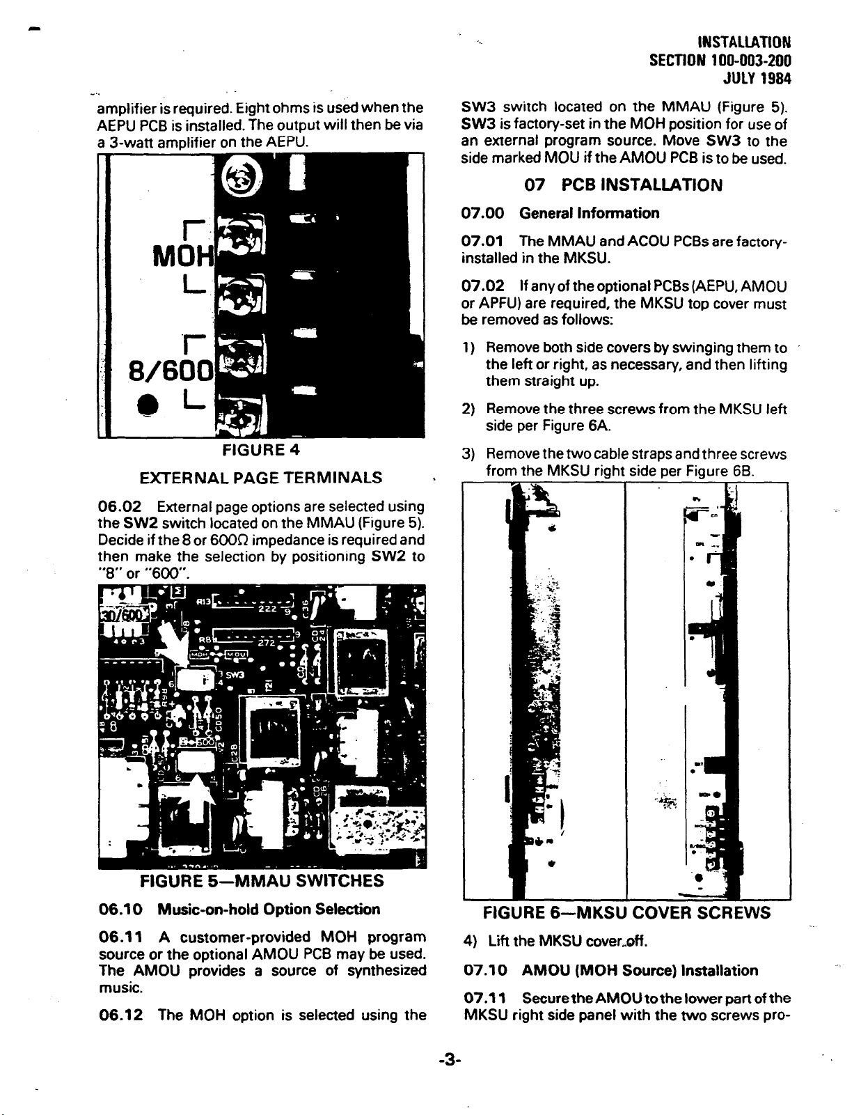
in the MKSU. A maximum of one card of each type
can be installed in the system (Figure 3). They are:
l
MMAU (KSU Main Unit)
l
ACOU (Central Office Unit)
l
Two types of ACOU are available:
a) MF-used when DTMF outpulsing is
required.
b) DP-used when rotary dial outpulsing -
is required.
l
AMOU (Music-on-hold Source)
l
Installed when Music-on-hold feature is
required without an external music source.
0 APFU (Power Failure Transfer Unit)
l
Provides a switch-over of all CO/PBX lines
to dedicated, customer-provided standard
telephones upon power failure.
l
AEPU (3-watt External Page Amplifier Unit)
l
Installed when the External Page feature is
required with no external PA amplifier.
The MMAU and ACOU PCB are factory-installed
in the MKSU.
s--s
- 2
-
.
FIGURE 2-WALL MOUNTED MKSU
05 PRINTED
CIRCUIT BOARD DESCRIPTIONS
05.01
A maximum of five PCBs can be installed
FIGURE 3-MKSU WITH PCBs
06 OPTION SELECTION
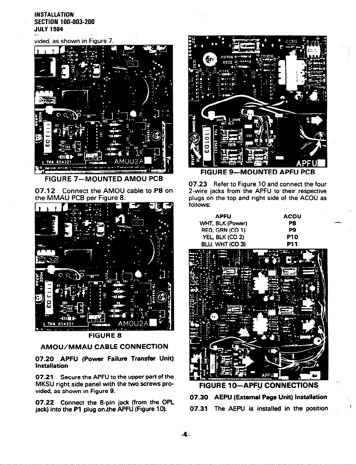
06.01 The external pag? output appears at the
terminals labeled 8/6OOkn the MKSU right side
panel (Figure 4). The output impedance can be
selected to be either 8R or 6OOR. and is facton/set for 6OOR. In the 6OOR mode an external PA
-2-
--
-.
:
Page 23
_..
amplifier is required. Eight ohms is used when the
AEPU PCB is installed. The output will then be via
a 3-watt amplifier on the AEPU.
‘..
INSTALlATlON
SECTION 100-003-200
JULY 1984
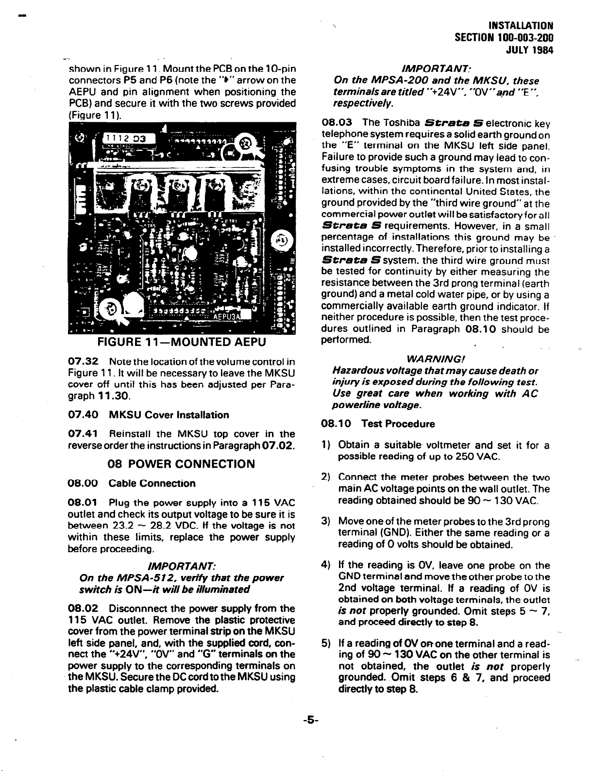
SW3 switch located on the MMAU (Figure 5).
SW3 is factory-set in the MOH position for use of
an external program source. Move SW3 to the
side marked MOU if the AMOU PCB is to be used.
07 PCB INSTALLATION
07.00 General Information
07.01 The MMAU and ACOU PCBs are factory-
installed in the MKSU.
07.02 If any of the optional PCBs (AEPU, AMOU
or APFU) are required, the MKSU top cover must
be removed as follows:
1) Remove both side covers by swinging them to
the left or right, as necessary, and then lifting
them straight up.
2) Remove the three screws from the MKSU left
side per Figure 6A.
FIGURE 4
EXTERNAL PAGE TERMINALS
06.02 External page options are selected using
the SW2 switch located on the MMAU (Figure 5).
Decide if the 8 or 6DOQ impedance is required and
then make the selection by positioning SW2 to
“8” or
3) Remove the two cable straps and three screws
from the MKSU right side per Figure 6B.
FIGURE 5-MMAU SWITCHES
06.10 Music-on-hold Option Selection
06.11 A customer-provided MOH program
source or the optional AMOU PCB may be used.
The AMOU provides a source of synthesized
music.
06.12 The MOH option is selected using the
FIGURE 6-MKSU COVER SCREWS
4) Lift the MKSU cover,&.
07.10 AMOU (MOH Source) Installation
07.11 Secure the AMOU to the lower part of the
MKSU right side panel with the two screws pro-
-3-
Page 24
INSTALLATION
SECTION 100-003-200
JULY
1994
v..
vided, as shown in Figure 7.
FIGURE 7-MOUNTED AMOU PCB
07.12
the MMAU PCB Der Figure 8.
Connect the AMOU cable to
PB
on
FIGURE g--MOUNTED APFU PCB
07.23 Refer to Figure 10 and connect the four
2-wire jacks from the APFU to their respective
plugs on the top and right side of the ACOU as
follows:
FIGURE 8
AMOWMMAU CABLE CONNECTION
07.20 APFU (Power Failure Transfer Unit)
Installation
07.21
MKSU right side panel with the two screws pro-
vided, as shown in Figure 9.
07.22 Connect the 8-pin jack (from the OPL
jack) into the
Secure the APFU to the upper part of the
Pl
plug on,the APFU (Figure 10).
APFU ACOU
WHT, Bu( (Power)
RED, GRN (CO 1)
YEL BU( (CO 2)
BLU, WHT (CO 3)
P8
PS
PlO
Pll
FIGURE lo-APF&j CONNECTIONS --.-
07.30 AEPU (External Page Unit) Installation
07.31
The AEPU is installed in the position
4
Page 25
e..
shown in Figure 11. Mount the PCB on the lo-pin
connectors P5 and P6 (note the “6” arrow on the
AEPU and pin alignment when positioning the
PCB) and secure it with the two screws provided
(Figure 11).
FIGURE 1 l-MOUNTED AEPU
07.32 Note the location of the volume control in
Figure 11. It will be necessary to leave the MKSU
cover off until this has been adjusted per Paragraph
07.40 MKSU Cover
07.41
11.30.
Installation
Reinstall the MKSU top cover in the
reverse order the instructions in Paragraph 07.02.
08 POWER CONNECTION
08.00 Cable Connection
08.01
Plug the power supply into a 115 VAC
outlet and check its output voltage to be sure it is
between 23.2 - 28.2 VDC. If the voltage is not
within these limits, replace the power supply
before proceeding.
IMPORTANT:
On the MPSA-512, verify that the power
switch is ON-it will be illuminated
08.02 Disconnnect the power supply from the
115 VAC outlet. Remove the plastic protective
cover from the power terminal strip on the MKSU
left side panel, and, with the supplied cord, connect the “+24V”, “OV” and “G” terminals on the
power supply to the corresponding terminals on
the MKSU. Secure the DC cord to the MKSU using
the plastic cable clamp provided.
INSTALLATION
SECTION 100-003-200
JULY 1984
IMPORTANT:
On the MPSA-200 and the MKSU. these
terminals are titled
respectively.
**+24V’-,
‘OV”qd “E “.
08.03 The Toshiba Strata S electronic key
telephone system requires a solid earth ground on
the “E” terminal on the MKSU left side panel.
Failure to provide such a ground may lead to confusing trouble symptoms in the system and, in
extreme cases, circuit board failure. In most instal-
lations, within the continental United States, the
ground provided by the “third wire ground” at the
commercial power outlet will be satisfactory for all
Strata S requirements. However, in a small
percentage of installations this ground may be
installed incorrectly. Therefore, prior to installing a
Strata S system, the third wire ground must
be tested for continuity by either measuring the
resistance between the 3rd prong terminal (earth
ground) and a metal cold water pipe, or by using a
commercially available earth ground indicator. If
neither procedure is possible, then the test procedures outlined in Paragraph 08.10 should be
performed.
WARNING!
Hazardous vottage that may cause death or
injury is exposed during the following test.
Use great care when working with AC
po werline voltage.
08.10 Test Procedure
Obtain a suitable voltmeter and set it for a
1)
.
possible reading of up to 250 VAC.
Connect the meter probes between the two
2)
main AC voltage points on the wall outlet. The
reading obtained should be 90 - 130 VAC.
Move one of the meter probes to the 3rd prong
3)
terminal (GND). Either the same reading or a
reading of 0 volts should be obtained.
If the reading is OV, leave one probe on the
4)
GND terminal and move the other probe to the
2nd voltage terminal. If a reading of OV is
obtained on both voltage terminals, the outlet
is not
properly grounded. Omit steps 5 - 7,
and proceed directly to step 8.
If a reading of OV onone terminal and a read-
5)
ing of 80 - 130 VAC on the other terminal is
not obtained, the outlet is not properly
grounded. Omit steps 6 & 7, and proceed
directly to step 8.
.
-5
Page 26
INSTALLATION
SECTION 100-003-200
JULY 1994
-..
6) If a reading of OV on one terminal and a reading of 90 - 130 VAC on the other terminal is
obtained, remove both probes from the outlet.
7) Set the meter on the “OHMS/Rxl” scale,
place one probe on the GND terminal and the
other probe on the terminal which produced a
reading of OV. A reading of less than IS2
should be obtained. If a reading of more than
1 R is obtained, the outlet is not adequately
grounded.
8) If the above tests show that the outlet is
improperly grounded, that condition should be 09.01 One 66ML50 split connection block (Fig-
corrected by a qualified electrician (per Article
250 of the National Electrical Code) before the distribution frame (MDFL
-
Strata S system is connected.
08.11 Ensure that the power switch on the
MKSU is
115 VAC outlet and measure the voltage at the
MKSU input terminals. Correct any problems
before proceeding.
OFF,
then plug the power supply-into the
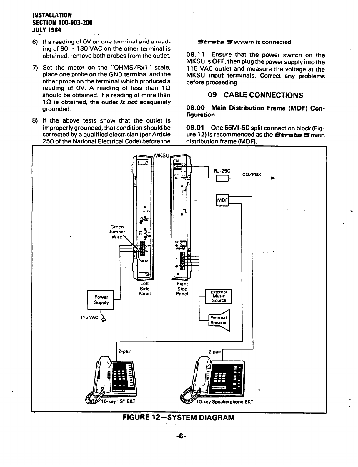
09 CABLE CONNECTIONS
09.00 Main Distribution Frame (MDF) Con-
figuration
ure 12) is recommended as the Strata Smain
MKSU
115VAC
-L-
P-pair 2-0ai.I
FIGURE 12-SYSTEM DIAGRAM
-6-
Page 27
‘k
INSTAUATION
SECTlON 100-003-200
JULY 1994
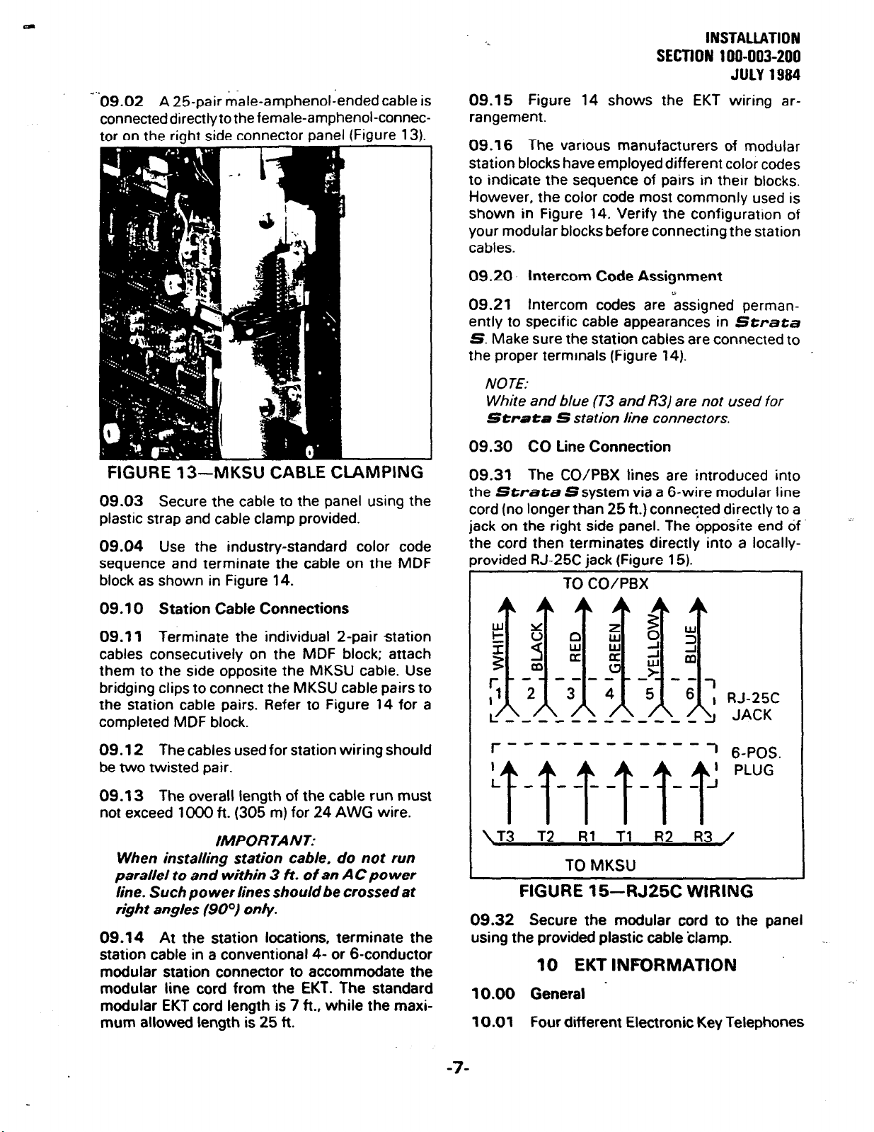
-‘09.02 A 25-pair &ale-amphenoliended cable is
connecteddirectlytothefemale-amphenol-connector on the riqht side connector panel
(Figure 13).
FIGURE 13-MKSU CABLE CLAMPING
09.03 Secure the cable to the panel using the
plastic strap and cable clamp provided.
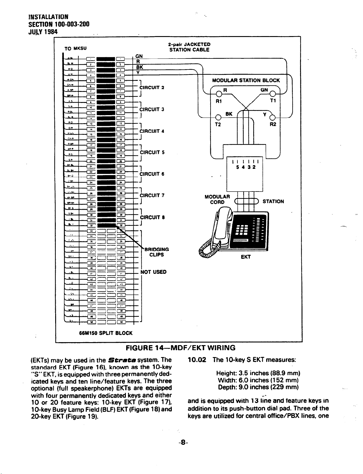
09.04 Use the industry-standard color code
sequence and terminate the cable on the MDF
block as shown
in Figure 14.
09.15 Figure 14 shows the EKT wiring arrangement.
09.16
station blocks have employed different color codes
to indicate the sequence of pairs in their blocks.
However, the color code most commonly used is
shown in Figure 14. Verify the configuration of
your modular blocks before connecting the station
cables.
The various manufacturers of modular
09.20 intercom Code Assignment
7
09.21 Intercom codes are assigned perman-
ently to specific cable appearances in Strata
S. Make sure the station
the proper terminals (Figure 14).
NOTE:
White and blue (T3 and R3/ are not used for
Strata S station line connectors.
cables are connected to
09.30 CO Line Connection
09.31
the Strata Ssystem via a 6-wire modular line
cord (no longer than 25 ft.) conneqted directly to a
jack on the right side panel. The opposite end df
The CO/PBX tines are introduced into
the cord then terminates directly into a locally-
rovided RJ-25C jack (Figure 15).
TO CO/PBX
09.10 Station Cable Connections
09.11
cables consecutively on the MDF block; attach
them to the side opposite the MKSU cable. Use
bridging clips to connect the MKSU cable pairs to
the station cable pairs. Refer to Figure 14 for a
completed MDF block.
09.12 The cables used for station wiring should
be two twisted pair.
09.13
not exceed 1 DO0 ft. (305 m) for 24 AWG wire.
parallel to and within 3 ft. of an AC po wer
Terminate the individual 2-pair station
The overall length of the cable run must
/MPORTANT:
When installing station cable, do not run
line. Such power lines should be crossed at
right angles (9OO) only.
09.14 At the station locations, terminate the
station cable in a conventional 4- or 6-conductor
modular station connector to accommodate the
modular line cord from the EKT. The standard
modular EKT cord length is 7 ft., while the maximum allowed length is 25 ft.
z
n
W
ki
a
a
-a
4
-w--v-------
r
3
I
-a
--
-?
RJ-25C
JACK
1 6-POS.
\T3 T2 Rl Tl R2 R3 /
TO MKSU
FIGURE 15-RJ25C WIRING
09.32 Secure the modular cord to the panel
using the provided plastic cable ‘clamp.
10 EKT INFORMATION
10.00 General .
10.01 Four different Electronic Key Telephones
-7-
Page 28
lNSTALl.ATlON
SECTION 100-003-200
JlJlv1994
TO MKSU
:
I-pair
JACKETED
STATION CABLE
'.
MODULAR STATION BLOCK
II
5432
- .
L
-El-l- Ynbu”
“7r:
%R
-c
--i
-7
66M160 SPLIT BLOCK
l-IcjUHt 14-MUi- tK I WlHlNIj
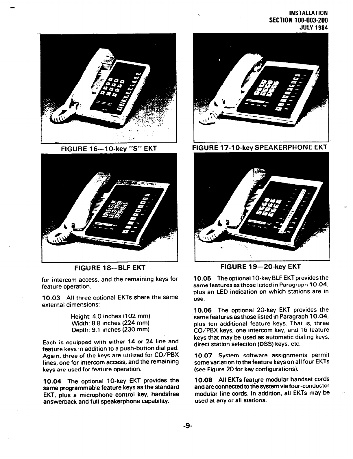
(EKTs) may be used in the
standard EKT (Figure 16). known as the 1 O-key
“S” EKT, is equipped with three permanentlyded-
icated keys and ten line/feature keys. The three
optional (full speakerphone) EKTs are equipped
with four permanently dedicated keys and either
10 or 20 feature keys: lo-key EKT (Figure 17).
1 O-key Busy Lamp Field (BLF) EKT (Figure 18) and
20-key EKT (Figure 19).
Strata
BRIDGING
CLIPS
idOT USED
I
system. The
I .... J
MODULAR
CORD
10.02
and is equipped with 13 line end feature keys in
addition to its push-button dial pad. Three of the
keys are utilized for central offiie/PBX lines, one
The lO-key S EKT measures:
Height: 3.5 inches (88.9 mm)
Width: 6.0 inches (152 mm)
Depth: 9.0 inches (229 mm)
STATION
I. -
-8-
Page 29
‘..
SECTION 100-003-200
INSTALLATION
JULY 1984
; ‘. _.
I
FIGURE 16-l
O-key
-.
“S” EKT
I
I
FIGURE 17-lo-key SPEAKERPHONE EKT
FIGURE 18-BLF EKT
for intercom access, and the remaining keys for
feature operation.
10.03 All three optional EKTs share the same
external dimensions:
Height: 4.0 inches (102 mm)
Width: 8.8 inches (224 mm)
Depth: 9.1 inches (230 mm)
Each is equipped with either 14 or 24 line and
feature keys in addition to a push-button dial pad.
Again, three of the keys are utilized for CO/PBX
lines, one for intercom access, and the remaining
keys are used for feature operation.
10.04 The optional lo-key EKT provides the
same programmable feature keys as the standard
EKT, plus a microphone control key, handsfree
answerback and full speakerphone capability.
FIGURE 19-20-key EKT
10.05 The optional 1 O-key BLF EKT provides the
same features as those listed in Paragraph 10.04,
plus an LED indication on which stations are in
use.
10.06
same featuresas those listed in Paragraph 10.04,
plus ten additional feature keys. That is, three
CO/PBX keys, one intercom key, and 16 feature
keys that may be used as automatic dialing keys,
direct station selection (DSS) keys, etc.
10.07 System software assignments permit
some variation to the feature keys on all four EKTs
(see Figure 20 for key configurations).
10.08 All EKTs feat_u_re modular handset cords -.
and are connected to the system via four-conductor
modular line cords. In addition, all EKTs may be
used at any or all stations.
The optional 20-key EKT provides the
-9-
Page 30
INSTALLATION
SECTION 100-003-200
JULY 1994 . -
PAU
-
H
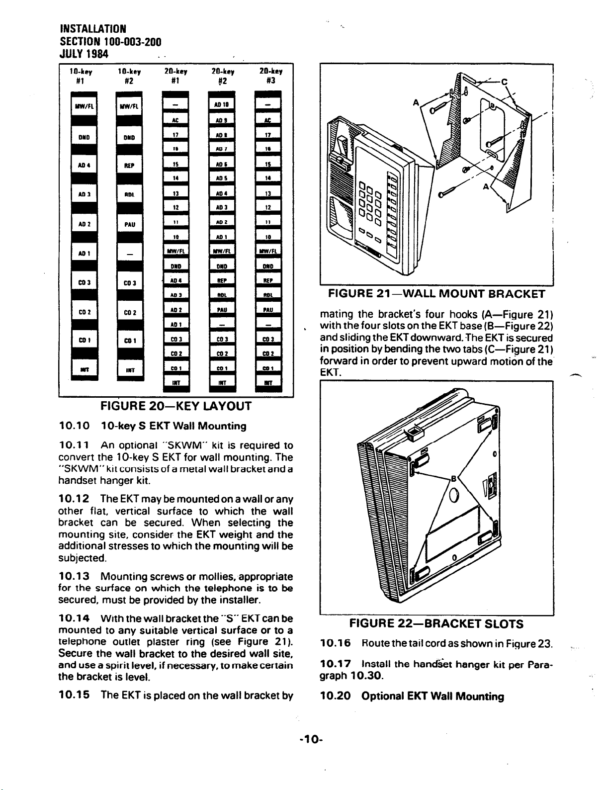
FIGURE 21 -WALL MOUNT BRACKET
mating the bracket’s four hooks (A-Figure 21)
with the four slots on the EKT base (B-Figure 22)
L
and sliding the EKTdownward. The EKT is secured
in position by bending the two tabs (C-Figure 21)
forward in order to orevent ubward motion of the.
EKT.
1
I.
FIGURE 20-KEY LAYOUT
10.10 1 O-key S EKT Wall Mounting
10.11 An optional ‘SKWM” kit is required to
convert the
“SKWM”
handset hanger kit.
10.12 TheEKTmaybemountedonawallorany
other flat, vertical surface to which the wall
bracket can be secured. When selecting the
mounting site, consider the EKT weight and the
additional stresses to which the mounting will be
subjected.
10.13 Mounting screws or mollies, appropriate
for the surface on which the telephone is to be
secured, must be provided by the installer.
10.14 With the wall bracket the “S” EKT can be
mounted to any suitable vertical surface or to a
telephone outlet plaster ring (see Figure 21).
Secure the wall bracket to the desired wall site,
and use a spirit level, if necessary, to make certain
the bracket is level.
10.15 The EKT is placed on the wall bracket by
IO-key S EKT for wall mounting. The
kit
consists of a metal wall bracket and a
I
FIGURE 22-BRACKET SLOTS
10.16
10.17 Install the handset hanger kit per Para-
graph 10.30.
10.20 Optional EKT Wall Mounting
Route the tail cord as shown in Figure 23. _.
-lO-
Page 31

*-
SECTlON 100-003-200
INSTALIATION
JULY 1994
knockouts are appropriate for the tail cord route,
and then cut them.
FIGURE 23-
10.21 An optional handset hanger kit (HWMA)
is also required to convert the optional EKTs for
wall mounting.
10.22 All optional EKTs are mounted in the
same manner, and they may be mounted on a wall
or any other flat, vertical surface to which the base
can be secured. When selecting the mounting
site, consider the EKT weight and the additional
stresses to which the mounting will be subjected.
10.23 Mounting screws or mollies, appropriate
for the surface on which the telephone is to be
secured, must be provided by the installer.
10.24 Locking tabs secure the EKT’s base. The
direction in which the base is attached to the EKT
determines whether it will be used as a desk unit
or wall unit (it is factory-configured as a desk unit).
Disengage the locking tabs by pushing downward
on the base (Figure 24).
“S” EKT WIRE ROUTING
FIGURE 25-EKT WIRE ACCESS
10.26 Secure the base to the desired wall site.
Use a spirit level and make certain the top of the
base is level and that the deeper portion is down.
10.27 Route the tail cord through the holes in
the base and secure the EKT (Figure 26).
-I
FIGURE 26-EKT WIRE ROUTING
10.28 Install the handset hanger kit per Para-
graph 10.30.
FIGURE 24
REMOVING OPTIONAL EKT BASE
10.25 Refer to Figure 25, choose which of the
10.30 Installing the Handset Hanger Kit
10.31
hanger kit (available from your Toshiba supplier)
must be used whenever an EKT is wall-mounted.
(When ordering specify if “S” EKT or optional
EKT-the HWMA is included in the SKWM kit.)
The remainder of the installation is the same for all
EKT types.
10.32 Remove the -card cover by inserting a
paper clip in the hole at one end. Bend the cover up
and remove it and the number card.
Refer to Figure 27, the optional handset
-ll-
Page 32

INSTALLATION
SECTION 100-003-200
JULY 1994
10.34 install the handset hanger into place and
tighten the screws. Reinstall the number card and
card cover.
. -
FIGURE 28-SET SWITCH
c) Depress the m key on station 17.
l
SPKR LED goes on.
d) Dial lqRm[ on the dial pad.
e) Depress the a and m keys.
l
The corresponding LEDs go on.
FIGURE 27-HANDSET HANGER KIT
10.35 An optional 13-ft. handset cord is available from your Toshiba supplier, and it is suggested that this cord be used when wall-mounting
an EKT.
10.40 EKT Connections
10.41 Connect the appropriate length line cord
to the modular connector, route the cord to the
EKT and connect to the EKT modular jack. Test the
EKT per Paragraph 12.
11 SYSTEM POWER-UP INITIALIZE
11 .Ol The
system data assignments stored in ROM that can
be entered at any time by performing the initialize
sequence outlined below. The system must be
initialized when it is first installed. This will allow
the system to be tested and any faults to be corrected before time is spent on programming.
11.02
refer to Figure 28 and perform the following steps:
a) Place the power switch on the MKSU in the
ON position.
b) Depress the SET switch and allow it to lock
. SETLEDgoeson.
l
Strcsta
S has a list of standard
To initialize the system data memory,
MW/FL LED on station 17 goes on.
f) Depress the IHoLD1 key.
l
The LEDs on station 17 for intercom through
I.
AD 4 begin flickering. ,
g) Depress and release the SET switch again.
. SET LED goes off.
l
Station 17 LEDs go off.
h) Cycle the MKSU power switch OFF and ON.
11 .l 0 Clearing Automatic Dialing
11 .l 1 The Automatic Dialing memon/ will con-
tain random numbers when the system is powered
up initially. To clear the memory; therefore pre-
venting meaningless numbers from being dialed,
proceed as follows:
a) Lock in the SET switch on the MKSU.
l
The SET LED and MW/FL LED on station
17willgoon.
b) Depress the m key on station 17.
l
SPKR LED will light steadily.
c) Dial mmrj on the dial pad.
l
SPKR LED will flash continuously.
d) Depress the a and m keys.
0 The corresponding LEDs will light
e) Depress the m] key.
l
All station 17 LEDs &xcept MW/FL) will go
Off.
f) Release the SET switch on the MKSU.
1.
-
-12-
Page 33

l
The SET LED and MW/FL LED on station
17 will go off.
,.
‘-
j) Depress the wj key.
. DND LED: off.
INSTALLATION
SECTION 100-003-200
JULY 1994
12 SYSTEM TEST PROCEDURES
12.00 1 O-key S EKT Functional Check
12.01 In order to verify the basic system func-
tions and confirm the proper functioning of the
EKT itself, perform the following test procedure at
each station equipped with a IO-key S EKT, begin-
ning with station 10.
12.02 With handset on-hook:
Depress the m!] key.
4
l
INT LED: l-use flash.
l
SPKR LED: on steady.
l
Listen for intercom dial tone via EKT
speaker.
Adjust speaker volume with the sliding volume
b)
control on the face of the EKT.
Depress the r6i] key.
c)
l
CO 1 LED: l-use flash.
l
SPKR LED: on steady.
l
Listen for CO/PBX dial tone via EKT
speaker.
Dial any digit (2 - 9) on the dial pad and dial
d)
tone will stop.
Depress the m] key.
e)
l
Listen for circuit break followed by dial
tone after approximately 2 seconds.
Depress the m key.
f)
l
CO 2 LED: l-use flash.
l
SPKR LED: on steady.
l
Listen for CO/PBX dial tone via EKT
speaker.
NOTE.
if no CO/PBX facility is connected to a CO
key, dial tone will not be heard but the LED is
still functional.
g) Depress the [ml key.
l
CO 3 LED: l-use flash.
l
SPKR LED: on steady.
l
Listen for CO/PBX dial tone via EKT
speaker.
h) Depress the IsPKRl key.
l
SPKR LED: off.
l
EKT speaker: off.
i) Depress the 1x1 key.
l
DND LED: on.
k) Depress the m key.
l
CO 1 LED: l-use flash.
l
SPKR LED: on steady.
l
Listen for CO/PBX dial tone via EKT
speaker.
I) Depress the WlDl key.
l
CO 1 LED: l-hold flash.
l
Speaker off (no dial tone).
. SPKR LED: off.
m) Depress the m key.
0 CO 1 LED: l-use flash.
l
SPKR LED: on steady.
l
Listen for CO/PBX dial tone via EKT ’
speaker.
n) Depress the ml key.
l
CO 1 LED: Conference call flash rate.
l
Dial tone continues.
o) Depress the m and m keys.
@ CO 1 LED: off.
. SPKR LED: off.
l
Dial tone: off.
.
p) Call EKT from another station.
l
Listen for caller’s voice via speaker after
the single tone signal.
l
Called station’s INT LED: l-called flash.
q) Dial q at calling station.
l
Tone signalling heard via the called station’s speaker.
r) Adjust the tone signalling volume with the
volume control on the bottom of the EKT.
s) Depress the m key.
l
INT LED: l-use flash.
l
SPKR LED: on.
l
Listen for intercom dial tone via the EKT
speaker.
t) Lift handset.
. SPKR LED: off.
l
Speaker: off.
l
Listen for dial tone via handset receiver.
.
u) Call another station and talk into the handset
transmitter.
l
Verify that your voice can be heard via -.
called EKT speaker.
v) Hang up.
12.03 This completes the station functional
-13-
Page 34

lNSTAU.ATlON
SECTION 100-003-200
JULY 1984
check for the standard EKT; repeat the procedure
for all standard EKTs in the system. See Paragraph
12.10 for optional EKT functional checks.
12.10 Optional EKT Functional Check
12.11 In order to verify the optional EKT’s func-
tions and confirm the proper functioning of the
EKT itself, perform the following test procedure on
each optional EKT.
12.12 With handset on-hook:
Depress the m key.
a)
0 INT LED: l-use flash.
l
SPKR LED: on steady.
l
MIC LED: on steady (if equipped).
l
Listen for intercom dial tone via the EKT
speaker.
Adjust speaker volume with the volume con-
b)
trol on the rear right-hand side of the EKT.
Depress the mj key.
d
l
CO 1 LED: l-use flash.
l
SPKR & MIC LEDs: on steady.
l
Listen for CO/PBX dial tone via the EKT
speaker.
Dial any digit (2
d)
- 9) on the dial pad and dial
tone will stop.
Depress the -1 key.
d
l
Listen for circuit break followed by dial
tone after approximately 2 seconds.
Depress the (co4 key.
f)
l
CO 2 LED: l-use flash.
l
SPKR & MIC LEDs: on steady.
l
Listen for CO/PBX dial tone via the EKT
speaker.
NOTE:
If no CO/PBX facility is connected to a CO
key. dial tone will not be heard but the LEO is
still functional.
g) Depress the m key.
l
CO 3 LED: l-use flash.
l
SPKR & MIC LEDs: on steady.
l
Listen for CO/PBX dial tone via the EKT
speaker.
h) Depress the m key.
. SPKR 81 MIC LEDs: off.
l
EKT speaker: off.
i) Depress the m key. .
l
DND LED: on.
Depress the m key.
j)
. DND LED: off.
Depress the m key.
W
l
CO 1 LED: l-use flash.
l
SPKR & MIC LEDs: on steady.
l
Listen for CO/PBX dial tone via the EKT
speaker.
Depress the [ml key.
l
CO 1 LED: l-hold flash.
l
Speaker: off (no dial tone).
. SPKR & MIC LEDs: off.
Depress the ml key.
m)
l
CO 1 LED: l-use flash.
l
SPKR & MIC LEDs: on steady.
l
Listen for CO/PBX dial tone via the EKT
speaker.
Depress the -1 key.
n)
0 CO 1 LED: Conference call flash rate.
l
Dial tone continues.
Depress the m and mj keys.
0)
. CO 1 LED: off.
.
. SPKR & MIC LEDs: off.
l
Dial tone: off.
Call EKT from another station.
P)
l
Listen for caller’s voice via the called EKT’s
speaker after the single tone signal.
l
Called station’s INT LED: l-called flash.
Dial q at calling station.
4)
l
Tone signalling heard via called EKT’s
speaker.
Adjust tone signalling volume with volume
r)
control on the rear left-hand side of the EKT
being tested.
Depress the m key.
9
l
INT LED: l-use flash.
l
SPKR & MIC LEDs: on steady.
l
Listen for intercom dial tone via the EKT
speaker.
Lift handset.
t)
. SPKR & MIC LEDs: off.
0 Speaker: off.
l
Listen for dial tone via the handset
receiver.
Call another station and talk into the handset
4
,. -
transmitter.
l
Verify that your voice can be heard via the
called EKT’s speaker.
-
_..~
-.
-14-
Page 35

-.‘v) Hold down the [ml key, and set the handset
back on-hook.
0 INT LED: l-use flash.
l
SPKR & MIC LEDs: on steady.
w) Tap the EKT microphone and verify that the
sound can be heard via the called EKT speaker.
x) Depress the (MUIE/MICI key while tapping the
microphone and verify that the sound cannot
be heard via the called EKT speaker (MIC LED
off momentarily-if equipped).
y) Depress the m key.
. INT LED: off.
. SPKR & MIC LEDs: off.
12.13 This completes the station functional
check for the optional EKTs; repeat the procedure
for all optional EKTs in the system.
12.20 Feature Check
'..
13.10 Music-on-Hold Source
13.11 A customer-provided MOH program
source (tape deck, tuner, or commercial source) or
the optional AMOU PCB may be used as the
music-on-hold source.
a) When the AMOU PCB is used, refer to Para-
graph 07.1 Ofor installation instructions. Verify
that the SW3 switch on the MMAU is set to
MOU (Figure 30). Adjust the volume with the
volume control labeled MOH on the MKSU
riaht side oanel.
SECTION 100-003-200
INSTALLATION
JULY 1984
12.21 Verify that all system features function
properly per Section 100-003-400, Operating
Procedures.
13 MISCELLANEOUS e
EQUIPMENT CONNECTIONS
13.00 Wiring Connections
13.01 All connections to the miscellaneous
equipment are made via the right side panel of the
MKSU. as shown
in Fiaure 29.
FIGURE 30-MMAU SW3 SWITCH
b) When a customer-provided source is used,
connect the MOH source to the MOH termi-
nals on the MKSU right side panel. The input
impedance is 6ODR. Verify that the SW3
switch on the MMAU is set to MOH (Figure
30). Adjust thevolume with the volume control
labeled MOH on the MKSU right side panel.
13.20 External Paging Connections
13.21 Strata Sprovides access to an exter-
nal paging system by dialing 8. The single output
connection is made via the 8/6DO terminals on
the MKSU right side panel, and can be used in one
of two ways:
a) Mount the optional 3-watt amplifier (AEPU
PCB) and connect the customer-provided
speaker cabling directly to the B/600 terminals (see Paragraph 13.30).
FlGURE29-MKSU CONNECTION STRIP
b) If more than 3 watts are required, an external
customer-provided amplifier can be connected
to operate the external speaker (see Paragraph
13.40).
13.30 Direct Exteri;ibl Speaker Connection
13.31 The exact number of speakers that may
be connected to the 8R, 3-watt output will depend
-15
Page 36

INSTALLATION
SECTION 100-003-200
JULY 1984
‘.
on the type of speaker used, the conductor resist-
ante, and the desired volume.
13.32 Install the AEPU PCB per Paragraph
07.30. The 8R output impedance must be selected
with the SW2 switch on the MMAU (Figure 31).
13.33 Connect the external speaker to the two
81600 terminals on the modular connector panel
on the MKSU.
13.34 Adjust the speaker volume with the
volume control on the AEPU PC8 (Figure 32).
FIGURE 31-MMAU SW2 SWITCH FIGURE 32-AEPU VOLUME SWITCH
ACOU
P9
PlO
Pl 1
FIG&E 33-POWER FAILURE TRANSFER DIAGRAM
-16-
Page 37

e..
13.40 External Amplifier Connection
13.41 If more power is required than the AEPU
amplifier can deliver, a customer-provided external amplifier may be connected to the 81600 ter-
minals on the MKSU (the AEPU is not required if
an external amplifier is used). The external speaker(s) should then be connected to the external
amplifier.
13.42 The 600R output impedance must be
selected with the SW2 switch on the MMAU (Fig-
ure 31).
13.43 The volume level through the system is
fixed, all adjustments must be made on the external amplifier.
INSTALLATION
SECTION 100-003-200
JULY 1984
13.51
designed, upon power failure, to switch the sys-
tem CO lines directly to dedicated- customer-
provided conventional telephones.
13.52 The MKSU must be equipped
APFU PC6 and the power failure telephones must
be directly compatible with the CO lines.
13.53
transfer feature is shown in Figure 33.
13.54 The power failure telephones are connected to the system via the jack labeled OPL on
the right side panel of the MKSU. The OPL jack
will accept either an 8-pin or 6-pin modular plug
(pins 1 & 8 are not used).
The power failure transfer feature is
with the
A simplified diagram of the power failure
13.50 Power Failure Transfer
13.55
Connect the telephones per Fiaure 34.
500/2500-TYPE’
TELEPHONES
*Depends on type of CO
FIGURE 34-PFT TELEPHONE CONNECTIONS
-17-
line.
Page 38

6c
TOSHIBA SYSTEM PRACTICES
ELECTRONIC KEY TELEPHONE SYSTEM
Strata S
MPSA-512 INSTALLATION
SECTION 100-003-250
JULY 1984
POWER SUPPLY
(MPSA-512)
a - .. --
INSTALLATION INSTRUCTIONS
Page 39

TOSHIBA SYSTEM PRACTICES
ELECTRONIC KEY TELEPHONE SYSTEM
MPSA-512 INSTALLATION INSTRUCTIONS
MPSA-512 INSTALLATION
SECTION 100-003-250
JULY 1984
Strata S
TABLE of CONTENTS
PARAGRAPH
TABLE of CONTENTS
ILLUSTRATION LIST
01 GENERAL
01 .oo Description
01.10 Mounting the MPSA
01.20
02
02.00
Fuses
POWER CONNECTION
MPSA Preparation
............................. 1
..............................
NUMBER
1
2
3
MPSA-512
Terminal Cover
Cable Connection .......................... 2
............................. 1
SUBJECT PAGE
........................ i
......................... i
........................... 1
....................... 1
........................ 1
.......................
.
. 1
ILLUSTRATION LIST
TITLE PAGE
........................... 1
1
Page 40

-.
01 .OO Description
01 .Ol The MPSA-512 power supply is perman-
ently configured for wall mounting. Its design will
not allow proper cooling if it is not mounted
upright as shown in Figure 1.
01 -GENERAL ’
‘-
01.13 Mark the screw locations on the mounting surface through the centers of the two keyholes in the MPSA. Use a spirit level to verify that
the drilling points are level.
01 .14 Lay the MPSA aside for the moment and
start the two screws into the wall at the marked
locations. Use l-%-inch panhead wood screws
(installer supplied), and stop when they have
penetrated to half their depth.
01 .15 Hang the MPSA on the two screws, and
tighten the screws.
NOTE:
If togglers are used see Section 100-003255, MPSA-200 installation, for the correct .
application.
01.20 Fuses
01.21 Remove the spare fuses from the hard-
ware carton, and store them in close vicinity to the
unit.
MPSA-512 INSTALLATION
SECTION 100-003-250
JULY
1994
FIGURE l-MPSA-512
01.02 Unpack and inspect the power supply and
the enclosed hardware. Examine the package and
make careful note of any visible damage. If any
damage is found, bring it to the attention of the
delivery carrier and make the proper claims.
01.03 Check the hardware list; if it is determined that any equipment within the carton is
missing, contact your Toshiba supplier immediately.
01.04 The following hardware, which is required to connect the MPSA to the system, is
supplied with each unit.
ENCLOSED HARDWARE
Quantity Item
2
2
1
AC Fuses-l spare
(2 amp, SLO-BLO 250VAC)
DC Fuses-l spare
(2 amp, Fast-BLO, 125VDC)
16 AWG, 3-wire Jacketed Cable
(54 inches)
01.22 Remove and inspect the fuses that were
shipped inside the MPSA. If either fuse is defective, replace it and order another’spare-fuse from
your Toshiba supplier.
02 POWER CONNECTION
02.00 MPSA Preparation
02.01 Verify that the power switch on the
MKSU is in the
MPSA power switch in the
02.02 Remove the plastic terminal strip cover
(Figure 2).
OFF
position, and then place the
OFF
position.
01 .lO Mounting the MPSA
01.11 The 30-inch MPSA power cord determines its relationship to an AC outlet.
01 .12 Choose a suitable vertical location for the
MPSA and place the unit on that location.
FIGURE 2-TERMINAL COVER
-l-
Page 41

MPSA-512 INSTALLATION
SECTION 100-003-250
JULY 1984
4..
02.03 Refer to Figure’3, and connect the power
supply cable in the following order:
White: +24V
Black: OV
Green:
G
FIGURE 3-CABLE CONNECTION
02.04 Refer to Paragraph 08, Section
003-200, installation, in order to complete cable
connection procedures.
lOO-
-2-
Page 42

-2
TOSHIBA SYSTEM PRACTICES
ELECTRONIC KEY TELEPHONE SYSTEM
MPSA-ZOO INSTALLATION
SECTION 100-003-255
JULY 1984
Strata S
- POWER SUPPLY
(MPSA-200) 4 -
INSTALLATION INSTRUCTIONS
Page 43

TOSHIBA SYSTEM PRACTICES
ELECTRONIC KEY TELEPHONE SYSTEM
MPSA-200 INSTALLATION INSTRUCTIONS
MPSA-200 INSTALLATION
SECTION 100-003-255
JULY 1984
Strata S
TABLE of CONTENTS
PARAGRAPH
01
01 .oo
01.10
01.20
01.30
02
02.00
02.10
02.20
02.30
02.40
02.50
NUMBER
SUBJECT
TABLE of CONTENTS
ILLUSTRATION LIST .........................
GENERAL
Description ...........................
Surface Preparation .......................
Mounting the MPSA .......................
Fuses
BATTERY BACKUP-INSTALLATION ..................
Description ...........................
TABLE A-Minimum Wire Gauge ...................
MPSA Preparation
installing the PBBU ........................
Required Labels and Warning Tags .................
Battery Connection .. 1 ....................
Installation Finalization ......................
.............................
........................
..........................
........................
ILLUSTRATION LIST
TITLE
.- .
PAGE
i
i
1
1
1
1
2
2
2
4
4
5
6
6.
6
PAGE
1
2
3
4
5
6
7
8
9
10
11
12
13
14
15
16
17
18
MPSA-2DO ..............................
Reversed MPSA Mounting Bracket ..................
Toggler
Toggler Insertion ..........................
Toggler Key
Toggler Screw
MPSA (Wall Mount Configuration) ...................
PBBU PCB
MPSA Control Panel .........................
MPSA Terminal Strip
Wire Harness in MPSA ........................
Harness Cable Clamp ........................
PBBU Mounting Screw ........................
MPSA Control Panel .........................
PBBU Mounting Pins ................ .: ..........
PBBU Heat Sink ...........................
Battery Terminal Attachment .....................
Recommended Wiring Diagram ....................
...............................
.............................
............................
.............................
........................
1
1
1
2
2
2
2
3
3
4
5
5
5
5 .
5
6
6
7
Page 44

YPSA-ZOO INSTALLATION
SECTION 100-003-255
JULY 1994
01 GENERAL
01 .OO Description
01 .Ol The MPSA-200 (Figure 1) is equipped
with a reversible, built-in bracket; it is configured
-
FIGURE 1 -MPSA-200
at the factory for mounting on a wail or other
vertical surface. In order to mount on a table or
horizontal surface securely, the bracket must be
reversed to the position shown in Figure 2. This
orientation is necessary to assure proper cooling
I
01.03 Check the hardware list; if it is determined that any equipment within the carton is
missing, contact your Toshiba supplier immediately.
01.04 The following hardware, which is re-
quired to mount and connect the MPSA to the
system, is supplied with each unit.
ENCLOSED HARDWARE
Quantity Item
2
2
T.C. Toggler Wall Fasteners
#14 Hex Head
Sheet Metal Screws
(Figure 3)
1 Toggler Key
1 Template
1 Spare AC Fuse
(Fl ,2.5 amp, SLO-EL0 125-VAC)
1 Spare DC Fuse
(F2, 5.0 amp, Fast-BLO, 32-VDC)
1
16 AWG, 3-wire Jacketed Cable
(54 inches)
Legs
FIGURE 2-REVERSED
MPSA MOUNTING BRACKET
01.02 Unpack and inspect the power supply and
the enclosed hardware. Examine the package and
make careful note of any visible damage. If any
damage is found, bring it to the attention of the
delivery carrier and make the proper claims.
FIGURE 3-TOGGLER
01.10 Surface Preparation
01 .l 1
Choose a suitable location (either vertical
or horizontal) for the MPSA and locate the template on that location. If on a wall, use a spirit level
to verify that the drilling points are level.
01.12 Place punch marks on the mounting surface through the two “+” marks on the template.
01 .13 Drill through the mounting surface
5/l 6-inch bit to prepare the anchoring holes.
01.20 Mounting the MPSA
01.21 Press the anchor legs of the togglers
together, and insert them into the anchoring holes
-l-
with
a
Page 45

MPSA-200 INSTALLATION
SECTION 1 W-003-255
JlJl.Y 1994
until their neck flanges are flush with the mounting surface (Figure 4). If insertion is difficult, tap
them lightly with a hammer.
-face
FIGURE 4-TOGGLER INSERTION
01.22 insert a toggler key into the small hole in
the neck of each fastener, as shown in Figure 5.
This should cause the anchor legs to “pop” open.
Remove the toggler key.
01.25 Position the power supply so that the narrower portions of the keyholes slip over the screws
(Figure 7), and (if the unit is wall-mounted) the
weight of the power supply is supported. Tighten
the screws.
Spread
Anchor
Legs
FIGURE 5-TOGGLER KEY
01.23 Thread the screws into the small holes in
the center of the togglers. Leave some clearance
between the bottom of each screw head and the
mounting surface (Figure 6).
Sheet
scl
T
F
FIGURE 6-TOGGLER SCREW
01.24 Place MPSA against the mounting surface with the screws protruding through the holes.
01.26 If. the power supply is table-mounted,
make certain the unit rests on its four .rubber
“feet” (this is essential for proper cooling) and
secured with the mounting bracket.
01.30 Fuses
01.31
ware carton, and place them in their individually
marked holders.
01.32 Remove and inspect the fuses that were
shipped inside the MPSA. If either fuse is defective, replace it and order another spare fuse from
your Toshiba supplier.
01.33 Connect the MPSA to the MKSU per
Paragraph 05.20, Section
lation. (If a power battery backup unit is to be
installed, see next paragraph.)
Remove the spare fuses from the hard-
100-003-200,
Instal-
02 BAlTERY BACKUP INSTALLATION
02.00 Description
02.01
Figure 8 is an optional PCB which may be installed
in the MPSA-200 to interface with two auxiliary
12 VDC batteries. In the event of an electrical
power failure, the PBBUprovides an automatic
battery power source, permitting a typical
Strata
tions for some time (in direct ratio with the type
and size of the batteries chosen).
The power battery backup unit (PBBU) in
S system to continue normal opera-
--
-2-
Page 46

MPSA-200 INSTALLATION
SECTION 100-003-255
JULY 1984
disrupted and existing calls would be disconnected).
02.03 When the normal source of electrical
power is restored. the voltage sensing circuit relay
will disconnect the standby battery power source.
02.04 If the standby battery power source output fails below 21 VDC while it is connected to the
system, the voltage sensing circuit will cause the
relay to disconnect the standby batteries from the
system.
FIGURE 8-PBBU PCB
02.02 The PBBU contains a voltage sensing circuit which causes an electro-mechanical relay to
connect the back-up battery power to the system
before the MPSA output voltage drops below 21
VDC (at which point system functions would be
02.05
nected unless:
0 The “Battery Override” switch (Figures 8 and,
l
The standby batteries will not be recon-
9) is placed in the ON position.
. . . or . . .
The depleted batteries are replaced by a freshly
charged pair and the “Battery Override” switch
is turned on and then released.
FIGURE 9-MPSA CONTROL PANEL
-3-
Page 47

MPSA-ZOO lNSTAUAllON
SECTION 100-603-255
JULY 1994
_..
02.06 The PBBU also contains circuitry to provide the charge current necessary to maintain the
batteries at a satisfactory level of charge while the
Strutu
S system is in normal operation. An
external fast charger may also be connected
across the battery output terminal connections.
02.07 The PSBU kii contains the following:
l
PBBU-power battery backup PCB.
l
Fuse-spare battery protection fuse.
l
“PBBU-4 RN”-decal to be placed on the
front of the MPSA.
l
“WARNING”-warning tag for attachment to
the 115 VAC power cord.
02.08 In addition to the kit, these installer-
-provided items are needed to install a PBBU.
l
Two Batteries-lead-acid, maintenance-free
automobile batteries (80 amp/hr maximum)
are recommended. The procedures in Paragraph 02.40 assume batteries with sidemounted terminals are used.
Battery Rack & Separator-a battery rack and
l
separator should be used to assure the batter-
ies will not tip and spill battery acid or acciden-
tally short the battery terminals.
l
Two-Wire Connecting Cable-a 2-wire connecting cable, terminating at one end with %in. ring terminals and at the other end with
‘%-in. spade terminals, is required to connect
the batteries and the MPSA. The minimum
wire gauge must be determined by the loop
length of the connecting cable (as indicated in
Table A).
l
Battery Protection--a XI-amp, 32V fuse, or a
1 O-amp DC instantaneous-tripping circuit
breaker, is required to protect the baiter&
from power surge or short circuit damage.
l
Bolts-four H x W-in. hex head bolts are required to connect the cable terminals to the
batteries.
l
Washers-eight %-in. flat washers and four
N-in. internal-tooth lock washers are required
for the above cable terminal connections.
l
Battery Cabinet-if the batteries are not located
in a well-ventilated closet or other secure area,
protected from fire or sparks, a properly venti-
lated protective cabinet is required to safeguard them.
CAUTION!
The power supply, battery, battery rack,
and the interconnecting wiring shall be
installed only by qualified installem. in accordance with al/applicable electrical codes
and Artic/e 480 of the National Electrical
Code. Before installing see the ‘*Install*
tion Instructionss”enclosed with each item.
fMFOt?TANTl
Only trained personnel may service or in-
stall the PBt?U and power supply.
02.10 MPSA Preparation
02.11 Verify that the power switch on the
MMAU is in the OFF position, and then disconnect
the 115 VAC power cord.
02.12 Remove the MPSA terminal strip cover
-.
TABLE A-MINIMUM WIRE GAUGE
LOOP LENGTH
12feet
20 feet
30 feet
50 feet
l
Single-Wire Cable-a 16 AWG single-wire
RECOMMENDED SIZE
16 gauge
14 gauge
12 gauge
lOgauge
cable, approximately 18 inches in length and
equipped with ring terminals, is required to
connect the two batteries in series.
l
Cable Clamp-a cable clamp should be used to
prevent cable movement from affecting the
batteries.
FIGURE lO-MPSA ~RMINAL STRIP
02.13
screws. Vrewing the MPSA as if it is wall-mounted,
two screws will be located on the front and four on
each side.
-4-
The f&A cover is secured by ten
Page 48

MPSA-200 INSTALLATION
SECTION 1 llO-003-255
JULY 1994
-‘. 02.14
02.15
02.16 Locate the multi-wire harness in MPSA
(Figure 1 1 ), it terminates in a nylon connector.
Remove ali ten screws.
Remove the
cover and
set it aside.
FIGURE 11 -WIRE HARNESS IN MPSA
02.17 The harness is loosely secured to the
chassis with a cable clamp (Figure 12); the clamp
will allow slight harness movement.
02.23 Slip the
override button through their respective ports in
the control panel (Figure 14). The PBBU mounting
bracket should be flush against the rear of the
control panel. The harness should flow around the
PBBU PCB, with no wires beneath it.
PBBU fuse
holder and battery
FIGURE 14-MPSA CONTROL PANEL
02.24
the two holes in the mounting bracket. The har-
ness should flow around the PB5U PCB, with no
wires beneath it (Figure 15). Press the pins into the
holes until they catch.
Align the two tan-colored PBBU pins with
FIGURE 12-HARNESS CABLE CLAMP
02.20 Installing the PBBU
02.21
trol panel; pop them out and discard.
02.22 Unwrap the PBBU. Remove and save the
screw located in the mounting bracket (Figure 13).
Two plugs are mounted in the MPSA con-
FIGURE 13-PBBU MOUNTING SCREW
FIGURE 15-PBBU MOUNTING PINS
02.25 Use the previously removed screw and
secure the mounting bracket to the control panel.
02.26 Plug the connector into the nine-hole
jack in the center of the PBBU.
prongs into the jack, they are keyed so that they
can be mated in only one position.
02.27
ness are caught between the cover and the PBBU
heat sink (Figure 16), and replace the MPSAcover.
Secure it with the ten screws originally removed.
-5-
Make certainthat no wires from the.har-
Do not
force the
Page 49

MPSA-200 INSTALLATION
SECTION
100-003-255
JULY 1994
02.42
and separator, which should be located in a min-
imum access area, such as a closet or a well
ventilated cabinet.
Secure the batteries in the battery rack
FIGURE 16-PBBU HEAT SINK
02.28
ure 14). If it catches and stays in, press it again to
cause it to release and protrude out of the control
panel. The button must be out for the MPSA to
operate normally.
02.29 Remove the spare fuse from the P88U
kit, and put it in the holder located on the top of the
MPSA.
02.30
02.31
tie it to the power cord where it connects to the
MPSA.
02.32 The “PBBU-4 REV”decal must be placed
on the control panel of the MPSA. Remove the
decal from the’kit, peel the backing off, and place it
on the control panel (Figure 14).
Depress the battery override button (Fig-
Required Labels and Warning Tags
Remove the warning tag from the kit and
02.40 Battery Connection
DANGER!
Do not attempt to connect the batteries to
the MPSA while the AC power cord is
plugged in, or without the MPSA being
connected to the MKSU. Do not connect
the two-wire cable to the batteries before
connecting it to the MPSA. Once the bat-
teries are connected to the MPSA the 24 V
output terminals are live.
02.41 Select a location for the batteries near
the power supply. The loop length of the cable
connecting them to the power supply will determine the minimum gauge wire which can be used
in the cable. See Table
The area in which the batteries are to be
locatedmustbe wellventilatedtopreventa
dangerous accumulation of battery gases.
The batteries must also be protected from
moisture and extreme temperatures.
A
DANGER!
02.43
in the OFF (out) position.
02.44 Loosen the two screws on the terminal
strip identified as 24V/BAllERY.
02.45 Connect the battery fuse (or circuit
breaker) lead to the negative terminal on battery
#l (Figure 17).
Lockwasher’
Verify that the battery override button is
Batters
Bolt/
r Terminal
FIGURE17 i _
BATTERY TERMINAL AlTACHMENT
02.46 Attach the negative wire of the 2-wire
cable to the battery fuse (or circuit breaker).
02.47 Connect the positive wire to the positive
terminal of battery #2 (see Figure 17).
02.48 Connect the two batteries with the single-wire cable--one end to the positive terminal
on battery #1 and the other end to the negative
terminal on battery #2 (Figure 18).
NOTE:
Place the cable clamp over the two-wire
cable and secure it to either the battery rack
or the protective cabinet. Adjust the clamp to
relieve strain on the cable.
02.50 Installation Finalization
02.51 Plug in the AC power cord, and verify that
the AC ON indicator is lit.
02.52
that the DC ON indicator is lit to indicate that the
batteries are supplying electrical power.
02.53 Replace the termi’r;al strip cover and test
the
and battery back-up power.
Unplug the AC power cord, and verify
Strata
Ssystem functions under both AC
-6-
Page 50

MPSA-200 INSTALLATION
SECTION 100-003-255
JULY 1984
Battery #2
1 ‘k m r + Marker
--
1 / 1 MPSA-200
r Clamp
--
0
--
A
si”g,&iz9yLJ
Cable
FIGURE 18--RECOMMENDED WIRING DIAGRAM
Battery Rack
and Separator
IMPORTANT!
When testing is complete, make certain that the
battery override button is in the OFF position
and that the AC ON indicator is lit.
To MKSU
Page 51

TOSHIBA SYSTEM PRACTICES
ELECTRONIC KEY TELEPHONE SYSTEM
SYSTEM PROGRAMMING
SECTION 1 oJo;I$3;;:
Strata S
PROGRAMMING PROCEDURES
Page 52

TOSHIBA SYSTEM PRACTICES
ELECTRONIC KEY TELEPHONE SYSTEM
FCC REGISTRATION
The
Strata S
electronic key telephone sys-
tem is registered in accordance with the provi-
sions of Part 68 of the Federal Communications
Commission’s Rules and Regulations.
TOSHIBA PUBLICATIONS
SECTlON 100-003-000
JULY 1984
You must notify the telephone company upon
final disconnection of your equipment.
RADIO FEQUENCY INTERFERENCE
FCC REQUIREMENTS
Means of Connection
The Federal Communications Commission (FCC)
has established rules which permit the
Strata
S electronic key telephone system to be connected directly to the telephone network. A
locally-provided jack is used for this connection-
jacks for this type of customer-provided equip:
ment will not be provided on party lines or coin
lines.
lncidence,of Harm
If
the
Strata S
system is malfunctioning, it
may also be disrupting the telephone network. The
system should be disconnected until the problem
can be determined and repaired. If this is not done,
the telephone company may temporarily disconnect service.
Telephone Network Compatibility
The telephone company may make changes in
its technical operations and procedures. If such
changes affect the compatibility or use of the
Strata S
system, the telephone company is
required to give adequate notice of changes.
Notification of Telephone Company
Before connecting a
Strata
Ssystem to the
telephone network, the telephone company must
be provided with the following:
1) Your telephone number
2) The FCC registration number (BF 287N-
13414KF-E)
3) The ringer equivalence number (0.5 B)
4) The USOC jack required (RJ-25C)
hems 2,8, and 4 are also indicated on the equipment laoel.
Warning:-This equipment generates and uses
radio frequency energy and if not installed and
used properly (that is, in strict accordance with the
manufacturer’s instructions), may cause interfer-
ence to radio and television reception. The equip-
ment has been type tested and found to comply
with the limits for a Class B computing device in
accordance with the specifications in Subpart J of
Pan 15 of FCC rules, which are designed to pro-
vide reasonable protection against such interfer-
ence in a residential installation. However, there is
no guarantee that interference will not occur. If
this equipment does cause interference to radio or
telelvision reception, which can be determined by
turning the equipment off and on, correct the
interference by one or more of the following
measures:
l
Reorient the receiving antenna.
+ Reorient the telephone equipment with res-
pect to the receiver.
l
Move the telephone equipment away from the
receiver.
l
Plug the key service unit into a different AC
outlet so that the KSU and receiver are on
different circuits.
If necessary, the user should consult the dealer
or an experienced radio/television technician for
additional suggestions. The user may find the fol-
lowing booklet, prepared bythe Federal Commun-
ications Commission, helpful: How Toldentifyand
Resolve Radio-TV Interference Problems. This
booklet is available from the U.S. Government
Printing Dffice, Washington, D.C. 20402, Stock
No. 004-OOO-OO345-4.
-.
Page 53

TOSHIBA SYSTEM PBACTICES
ELECTBONIC KEY TELEPHONE SYSTEM SECTION 100-003-300
e..
SYSTEM PROGRAMMING
JULY 1984
Strata S
SYSTEM PROGRAMMING PROCEDURES
TABLE of CONTENTS
PARAGRAPH SUBJECT
01
02
02.00
02.10
02.20
02.30
02.40
02.50
02.60
02.70
TABLE of CONTENTS
INTRODUCTION 1
PROGRAMMlNGPkdCEdUkES”::::::::::::::::::: 1
General
Multiple Station Programming
Preparation
System Options
01 Program-System Assignments
05 Program-Automatic Recall From Hold Timing
CO Line Options
06 Program-Automatic Reiease dn’Hbld Enabl’e * : : : : : : : : :
07 Program-Automatic Release on Hold Timing
10 Program-PBX Backup
1 X Program-PBX Access Codes
20 Program-Toll Restriction Disable’ * : : 1 : : : 1 : : : : : : : 3
2X Program-Toll Restriction Exception Codes
Station Options
3XX Program-Station CO Line Access
4XX Program-Station Type and Flexible Key Assignment
5XX Program-Station Class of Service 4
6XX Program-Toll Restriction Classification * : : : : : : : : : : : 4
7XX Program-Station Outgoing Call Restriction
8XX Program-CO Ringing Assignments-Day
9xX Program-CO Ringing Assignments-Night 4
FIGURE l-EKT Key Assignments
TABLE l-System Record Sheet
Initialization
System Data En&
TABLE 2-Initialized Data’ : : : : : : : : : : : : : : : : : : : : : : : 10
PROGRAM TABLE LIST
TABLE 3-Program 01 -System Assignments
TABLE 4-Program 05-Automatic Recall From Hold Timing
TABLE 5-Program D6-Automatic Release on Hold Enable
TABLE 6-Program 07-Automatic Release on Hold Timing ........
TABLE 7-Program lo-PBX Backup 16
TABLE 8-Program 1X-PBX Access Codes * : : : : : 1 : : : : : : : : : 17
TABLE g--Program 20-Toll Restriction Disable
TABLE lD-Program 2X-Toll Restriction Exception Cddds ’ : : : : : : : : : 19
TABLE 1 l-Program 3XX-Station CO Line Access
TABLE 12-Program 4XX-Station Type & Flexible Key Assignment
TABLE 13-Program SXX-Station Class of Service .
TABLE 14-Program 6xX-Toll Restriction Classification
TABLE 1 !&Program 7XX-Station Outgoing Call Restriction ........ 24
TABLE 16-Program 8xX-CO Ringing Assignments-Day
TABLE 17-Program 9xX-CO Ringing Assignments-Night
.............................
...........................
........................
...................
.........................
...................
.........................
.......... : : : : : : : : : 5
....................
.........................
.......................
...............
.............
..............
............
......... 3
... ; ..... 3
............
.....
.........
..........
........
........
.......
.
-:
.......
........
........
: : : : 22
PAGE
i
1
2
2 .
2
2
3
3
3
3
3
3
3
3
4
4
6
10
10
11
12
13
14
15
18
20
21
23’
25
26
Page 54

SYSTEM PROGWMING
SECTION 100403-300
JULY 1984
01 INTRODUCTION
01 .Ol The data governing overall system operation and feature execution for Strcrm S is
stored in read-only-memory (ROM) and cannot
be altered in the field. However, thedata controlling operation of the various options, both sys-
tem and station, is stored in random-access-
memory (RAM) and can easily be changed ac-
cording to individual installation requirements.
01.02 All Stretir S options are controlled
by selections made in the system data tables. An
initialization process is provided for verifying
predetermined system assignments. The installer can then proceed with any necessary
changes.
01.03 All system data changes are made via
station 17 (as the input/output device). Whenever the system is placed in the programming
mode, the keys on station 17 are used to enter
data while its LEDs display the current data.
While station 17 is in the programming mode,
the remainder of the system may still be used in
the usual fashion.
01.04 A memory back-up battery is provided
to prevent loss of system data memory in the
event of a power failure.
NOTE:
Whenever a system is installed, the system
must be initialized. See Paragraph 02.60.
02 PROGRAMMING PROCEDURES
02.00 General
02.01 The
in the programming mode before system data
can be verified or altered. With the exception of
station 17, normal system functions are not
suspended while in the programming mode. For
convenience, station 17 can be moved from its
usual location and plugged directly into the jack
marked “EKT” on the right side panel of the
KSU. The EKT at the normal station 17 location
must be disconnected when this jack is used.
StrataS
system must be placed
In the majority of programs(Type l), them,
m and mkeys are used to change “bits”
of system data. The LEDs associated with the
various keys show the status of that “bit”
before and after key operation. A particular
key and LED will have a different meaning,
depending upon the program number being
used.
In Type 2 programs, the dial pad is used to
enter data. In this case, the system, using the
INT, CO and selected AD LEDs, verifies the
entered data by displaying the number in
Binary format.
02.03 The programming mode is activated by
locking in the SET switch on the switch panel
and then depressing the m] key on station
17. After the station has been activated, a pro-
gram number is dialed on the station dial pad,
and the system will respond as follows:
Type 1 programs:
Station 17 LEDs will display the existing data
in these categories.
Type 2 programs:
AD 2 LED on station 17 will flash continuously. Actual data may be reviewed without
alteration by multiple operation of the @
key.
02.04 Data can be altered while it is being
displayed. To input new data via station 17, perform the following:
Type 1 programs:
The state of an LED is altered by depressing
its associated key. Depressing the key while
the LED is “on” will turn it off and vice-versa.
Type 2 programs:
Data is entered via the dial pad. The LEDs
will display the data and digit number in
Binary format.
02.05 Once the desired data is entered and
displayed, it is written into memory by depress-
ing the I=] key on station 17.
02.02 When the system is in the programming mode, station 17 is used to enter the sys-
tem data in one of two ways:
NOTE:
AI/ tables and procedures that follow as-
sume station 17 has the ‘Standard” key
pattern
and A~\N/FL ).
INT , 1-1, ml, m]
23
System and CO line options are written into
temporary storage when the /m] key is
depressed. After all changes in these categories have been made, transfer the data
into working memory per Paragraph 02.06.
Station option data (with the exception of CO
line access assignments} are written into the
main data memory; therefore, all changes
-l-
Page 55
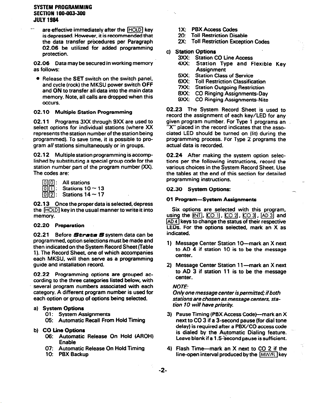
SYSTEM PROGRAMMING
SECTION 1 W-993-399
JULY 1994
m..
are effective immediately after the I=] key
is depressed. However, it is recommended that
the data transfer procedures per Paragraph
02.06 be utilized for added programming
protection.
02.06 Data may be secured in working memory
as follows:
l
Release the SET switch on the switch panel,
and cycle (rock) the MKSU power switch OFF
and ON to transfer all data into the main data
memory. Note, all calls are dropped when this
occurs.
02.10 Multiple Station Programming
02.11
select options for individual stations (where XX
represents the station number of the station being
programmed). To save time, it is possible to program a// stations simultaneously or in groups.
Programs 3XX through 9xX are used to
1X: PBX Access Codes
20: Toll Restriction Disable
2X: Toll Restriction Exception Codes
c) Station
3XX: Station CO Line Access
4XX: Station Type and Flexible Key
5xX: Station Class of Service
6xX: Toll Restriction Classification
7XX: Station Outgoing Restriction
8XX: CO Ringing Assignments-Day
9xX: CO Ringing Assignments-Nite
02.23 The System Record Sheet is used to
record the assignment of each key/LED for any
given program number. For Type 1 programs an _
“X” placed in the record indicates that the associated LED should be turned on (lit) during the
programming process. For Type 2 programs the
actual data is recorded
Options
Assignment
02.12 Multiple station programming is accomplished by substituting a special group code for the
station number part of the program number (XX).
The codes are:
q
m : All stations
q
m: Stations 10 N 13
0121: Stations 14-17
02.13 Once the proper data is selected, depress
the [m[ key in the usual manner to write it into
memory.
02.20 Preparation
02.21
programmed, option selections must be made and
then indicated on the System Record Sheet (Table
1). The Record Sheet, one of which accompanies
each MKSU, will then serve as a programming
guide and installation record.
02.22 Programming. options are grouped according to the three categories listed below, with
several program numbers associated with each
category. A different program number is used for
each option or group of options being selected.
a)
b)
Before Strsea Ssystem data can be
System Options
01: System Assignments
05: Automatic Recall From Hold Timing
CO Line Options
06: Automatic Release On Hold (AROH)
Enable
07: Automatic Release On Hold Timing
10: PBX Backup
02.24 After making the system option selections per the following instructions, record the
various choices in the System Record Sheet. Use
the tables at the end of this section for detailed
programming instructions. .
02.30 System Options:
01 Program-System Assignments
Six options are selected with this program,
usin
I3
LEDs. For the options selected, mark an X as
indicated.
1) Message Center Station 1 D-mark an X next
2) Message Center Station 1 l-mark an X next
3) Pause Timing (PBX Access Code)-mark an X
4) Flash Time-mark an X next to CO 2 if the
the m, Lo, m, m, m3( and
AD 4 keys to change the status of their respective
to AD 4 if station 10 is to be the message
center.
to AD 3 if station 11 is to be the message
center.
NOTE:
Only one message center is permitted; if both
stations are chosen as message centers, sta-
tion 10 will have priority.
next to CO 3 if a 3-second pause (for dial tone
delay) is required after a PBX/CO access code
is dialed by the Automatic Dialing feature.
Leave blank if a 1.5&cond pause is sufficient.
line-open interval produced by the Im] key
-2-
Page 56

‘.
SYSTEM PROGRAMMiNG
SECTION 1 W-oo3-3oo
JULY 1984
is to be 0.5-second for behind PBX operation.
Leave blank if the 2.0-second flash for dial
tone recall is required.
Station 10 DND/NITE Key-mark an X next to
5)
CO 1 if the IDND/NITEJ key on station 10 is to be
a DND key. leave blank if mkey is required.
Tone First-mark an X next to INT if Tone First
6)
intercom signalling is required. Leave blank if
Voice First signailing is required.
05
Program-Automatic Recall From Hold Timing
Sets the timing for the Automatic Recall From
Hold feature.
1) If a recall is desired, select a time period of 16
- 160 seconds and mark an X next to the
appropriate key in the System Record Sheet.
The times are not accumulative-only one key
can be selected.
2) If no recall is required, mark an X next to INT.
02.40 CO tine Options
06 Program-Automatic Release On Hold
Enable
Selects whether or not the Automatic Release
On Hold (AROH) feature is to function on a given
CO line; the CO line keys represent themselves.
l
Mark an X next to each CO line that requires
AROH.
07 Program-Automatic Release On Hold
Timing
Informs the system of the access codes
US& by
the PBX that is connected to the linesselected in
Program 10. Strcrtcr will recognize the access
codes and react appropriately for Toll Restriction,
Automatic Dialing and Repeat Last Number Dialed.
l
Enter the actual access codes (maximum: 8).
NO
JE:
If the access code is a sibgle digit, enter ****‘in
the second column. lf all combinations follo wing a particular first digit are to be considered access codes (e.g. 91, 92, 93, etc.).
enter “D ‘# (do not care) in the second column.
20 Program-Toll Restriction Disable
Selects whether or not the Toll Restriction feature is to function on a given CO line; the CO line
keys represent themselves.
l
Mark an X next to each CO line on which Toll
Restriction is not to function.
’ 2X Program-Toll Restriction Exception Codes
Informs the system of a maximum of five 4-digit
codes (area codes or office codesjthat are allowed
to be dialed by Toll Restricted stations.
l
Enter the actual 4-digit codes (maximum: 5).
NO
JES:
1) Stations allowed access to codes 1, 2.
and 3 may dial up to seven dig& following the 4-digit codes.
2) Stations allowed access to codes 4 and 5
may dial up to 29 dig& (for MCI. SPRINT,
etc.) following the 4-digit codes.
Selects Cross Bar (XB) or ESS timing for the
AROH feature using each CO line key to represent
itself.
l
Mark an X next to each CO line that requires
XB timing; leave blank if ESS timing is required.
NO
JE:
Program 07 will have no meaning if AROH
was rejected in Program 06.
10 Program-PBX Backup
Informs the system if the CO line key is actually
connected to a PBX station line. The system will
recognize PBX access codes on selected line(s).
l
Mark an X next to each CO line that is to be
connected to a PBX station line.
1 X Program-PBX Access Codes
02.40 Station Options
3XX Program-Station
CO
tine Access
The ability of an individual station to access any
of the CO lines is determined by selections made
using this program. A station denied access to a
CO line by this program will have neither key nor
LED functions for that CO line. Selections must be
repeated for all stations.
l
Mark an X next to each .CO line that is to be
:
accessed by the station in question,
4XX Program-Station Type and Flexible Key
Assignment
Informs the system of the type and style telephone being used at each station (see Figure 1 for
representative key designation strips). Selection
must be made for each station.
-3-
Page 57

SYSTEM PROGRAMMING
SECTlON 100-903-399
JULY 1994
e..
1) Mark an X next to CO 2 if the EKT is equipped
with 1 O-key #2 or 20-key #3 configuration.
Mark an X next to AD 3 if the station will be
2)
allowed to dial 911 and 800 numbers.
2) MarkanXnexttoCO 1 iftheEKTistohavethe
1 O-key #l or 20-key #2 configuration.
3) Mark an X next to INT if the EKT is to have the
1 O-key #l or 20-key #l .
NOTE:
Instructions #I and #3 cover all available
EK Ts, #2 is a 20-key exclusive (see Figure 1 I.
5XX Program-Station Class of Service
Six options are selected with this program,
using m, a and JAD keys to change the status of their respective LEDs. The selections listed
below must be repeated for each station. In all
cases, mark an X where indicated:
1) Privacy Override-mark an X next to AD 4 if
the station is allowed the Privacy Override
feature.
NOTE:
A maximum of two stations are permirred to
use the Privacy Override feature. If more than
two are programmed, only the two lowest
numbered stations wiiibe allowed to use this
feature and the others will be ignored
DND Override-mark an X next to AD 3 if the
2)
station is allowed the DND Override feature.
Speakerphone-mark an X next to CO 3 if the
3)
station is allowed to use the Speakerphone
feature (optional EKT).
Microphone Control-mark an X next to CO 2
4)
if the station’s speakerphone isallowed push-
on/push-off microphone control.
Automatic Line Preferenc-arkan X next to
5)
CO 1 if the station is allowed the Automatic
Line Preference feature.
All Call-mark an X next to INT if the station is
6)
included in an All Call page.
6XX Program-Toll Restriction Classification
Eight different Toll Restriction Classifications
may be selected by this program using the m,
m and mkeys. DefinestypeofToll Restriction
that will be functional on individual stations.
Selections must be made for each station:
Mark an X next to AD 2 if the station will be
3)
allowed to dial 1 + 7digit number.
Mark an X next to AD 1 if the station will be
4)
restricted to dialing 7digit numbers.
Mark an X next to CO 3 if the station will be
5)
restricted from dialing 0 as the first number.
Mark an X next to CO 2 if the station will be
6)
restricted from dialing 0 as the second number.
Mark an X next to CO 1 if the station will be
7)
restricted from dialing 1 as the first number.
Mark an X next to INT if the station will be
8)
mstricted from dialing 1 as the second number.
NOTE:
The exception codes (4 digas) may be pro-
grammed using Program 2X These codes
can be any combination of digits and will
cause tollrestriction to be bypassed-tollrestriction may be disabled on’ a system-wide
per-CO line basis using Program 20.
7XX Program-Station Outgoing Call Re- striction
Restricts a station from outgoing access to any
number of CO lines while leaving it free to answer
these lines when they are ringing or on hold.
Selections must be made for each station.
l
Mark an X next to the CO line that is to have
restricted access by the station in question.
8XX Program-CO Ringing Assignments-Day
Selects which CO lines will ring at a given station when the system is in the “DAY” mode.
Selections must be made for each station.
l
Mark an X next to each CO line that is to ring at
the station in question.
9xX Program-CO Ringing Assignment-Night
Selects which CO line will ring at a given station
when the system is in the “NITE” mode. Selections must be made for each station.
l
Mark an X next to each CO line that is to ring at -.
the station in question.
1) Mark an X next to AD 4 if ihe station will be
allowed to dial 411.
-4
Page 58

SYSTEM PROGRAMMING
SECTION 100-003-300
JULY 1994
1 O-key EKT #1
YW/FL
1 O-key Ett
MW/FL
I
b-4
1 DND 1
AD4
I I
AD 3
I I
AD 2
I I
AD 1
I
I
I
DND
REP
PAU
r#2 20-key EKT ##1
20-key EKT #2
PO-key EKT ##3
CD 3
H
I
I
I
CD 3
CD 2
CD 1
FIG1
RE l-EKT KEY ASSIGNMENTS
-5-
Page 59

SYSTEM PROGfIAMMlNG
SECTlON 1 W-993-399
JULY 1994
v..
X = Select (LED on) Initialized Data: AD 4 LED on; all other LEDs off
NOTE:
Only one Message Center is permitted; if both stations 10 and 11
are chosen as Message Centers. station IO will have priority.
AUTOMATIC RECALL FROM HOLD TIMING
TABLE 1
SYSTEM RECORD SHEET
PROGRAM 01 -SYSTEM ASSIGNMENTS
PROGRAM 05
KEY/LED X TIME
CO LINE OPTIONS
PROGRAM 06
AUTOMATIC RELEASE
ON HOLD ENABLE
A04 160 Seconds
AD3 128 Sfxotlds
A02 96 Seconds
AD1 64 Seconds
co3 46 seconds
co2 32 Seconds
co 1 16 Seconds
IN1 No Recall
X = Select (LED on)
Initialized Data: 32 Seconds
AUTOMATIC RELEASE
I
; -.-:
PROGRAM 07
ON HOLD TIMING
-.
X = Enable (LED on)
Initialized Data:
All LEDs off
X = X8 (LED on)
Initialized Data:
All LEDs off
-6-
Page 60

PROGRAM lo-PBX BACKUP
X = Connected to PBX line (LED on)
Initialized Data: All LEDs off
PROGRAM 1X-PBX ACCESS CODES
SYSTEM PROGRAMMING
SECTION 100-003-3790
JULY 1994
Enter Access Codes (maximum: 8)
Initialized Data: None
NOTE:
If the access code is a single digit, enter
“**’ in the second column. If all
combinations following a particular first digtl are to be considered access
codes (e.g., 9 I, 92,93, etc.), enter “D” (do not care) in the second column.
PROGRAM 20~TOLL RESTRICTION DISABLE
X = Disable (LED on)
Initialized Data: All LEDs off
PROGRAM 2X-TOLL RESTRICTION EXCEPTION CODES
CODE FIRST SECOND THlRD FOURTH
#l (21)
#3(23)
~(24)
Enter actual Exception Codes (maximum: 5)
Initialized Data: None
NOTE:
ff codes are less than four dig&, enter -**’ in the remaining spaces.
-7-
Page 61

SYSTEM PROGRAMMING
SECTION 100-003-3OU ‘.
JULY 1984
v..
PROGRAM SXX-STATION CO LINE ACCESS
X = Select (LED on) Initialized Data: All LEDs on
PROGRAM 4XX-STATION TYPE and FLEXIBLE KEY ASSIGNMENT
(See figure 1)
X = Select (LED on) Initialized Data: INT LED on; all other LEDs off
PROGRAM SXX-STATION CLASS OF SERVICE
KEY/LED FEATURE
AD4
AD3
co3
co2
CO1
INT
Privacy Override Allowed
DND Overrii Allowed
SVEnaMd
Microphone Push-am/Push-off
Auto tin, Prehrence Allowed
Include in All Call
STATION NUMBERS
lOtllll2Il3l14l1Sll6Il
X = Sele ct (LED on) Initialized Data: COs 3 & 1 & INT LEDs on; other LEDs off
PROGRAM 6xX-TOLL RESTRICTION CLASSIFICATION
KEY/LED FEATURE
AD4
AD3 . Allow911 and800
AD2
AD1
co3
co2
CO1
INT
Allow 411
Allow 1 + 7 digits
Restrict more than 7 digits
RestriuDas lstdiait
Restrict 0 as 2nd digit
Restrict 1 as lstdigit
Restrict 1 as 2nd digit
STATION NUMBERS
1011121314151S17
X = Select (LED on) Initialized Data: No Restriction
-8-
Page 62

SYSTEM PROGRAMMING
SECTION 100-003-390
PROGRAM 7XX-STATION OUTGOING CALL RESTRICTION
JULY 1984
KEY/LED
co3
co2
co 1
Restricted
Restricted
Restricted
FEATU R E
X = Select (LED on) Initialized Data:
STATION NUMBERS
101112131416161~
All
LEDs off
PROGRAM 8xX-CO RINGING ASSIGNMENTS-DAY
KEY/LED FEATURE
co3
co2
co 1
Ring in Day
Ring in Day
Ring in Day
X = Select (LED on) Initialized Data: Station 1 O-all LEDs on; all others off
STATION NUMBERS
1011121314151617
PROGRAM SXX-CO RINGING ASSIGNMENTS-NITE
I
X = Select (LED on) Initialized Data: Station 11 -all LEDs on; all others off
-s-
Page 63

SYSTEM PROGRAMMING
.SECTlON 100-003-300
J@Y 1994
02.60 Initialization
02.61 Sfwate
data assignments stored in ROM that can be
entered anytime by initializing the system. The
system must be initialized when it is first installed.
This will allow the system to be tested and any
faults to be corrected before time is spent on programming. Standard data assignments are listed
in Table 2.
02.62 To initialize the
Make sure the power switch on the MKSU
switch panel is in the ON position.
Depress the SET switch on the switch panel
b)
and allow it to lock.
l
The SET LED lights.
0 The MW/FL LED on station 17 lights.
. -
S has a list of standard system
Strata
S system:
a) Lock in the SET switch on the MKSU.
l
The.SET LED and MW/FL LED on station
17 will go on.
b) Depress the 1-1 key on station 17.
l
SPKR LED will light steadily.
c) Dial l~(~(R on the dial pad.
0 SPKR LED will flash continuously.
d) Depress the m and (COlkeys.
l
Corresponding LEDs will light steadily.
e) Depress the /ml key.
l
All station 17 LEDs (except MW/FL) will go
Off.
f) Release the SET switch.
l
The SET LED and MW/FL LED on station
17 will go off.
02.70 System Data Entry
Depress the I=] key on station 17.
d
l
The SPKR LED lights.
02.71
System Data is entered via station 17
while the system is in the “programming mode”.
Dial flmmj on the dial pad.
d)
02.72 The system is placed in the programming
Depress the I] and \co] keys.
e)
l
The corresponding LEDs light.
Depress the (ml key on station 17.
f)
l
The INT - AD 4 LEDs will flash continuously.
Depress and release the SET switch again.
9)
l
Station 17 LEDs stop flashing and return to
usual indication.
Cycle the power switch OFF and ON.
h)
02.63 The Automatic Dialing memory will contain random numbers when the system is powered
up initially. Therefore, it is necessary to clear the
memory to prevent meaningless numbers from
mode by locking in the SET switch on the MKSU.
The SET LED and MW/FL LED on station 17 will
light while the system is in the programming mode.
NOTE
All tables andprocedures that follow assume
station 17 has the ‘standard* key pattern
(IINTI. [cod, pin=& /EGq, Irn]).
02.73 Once the system is in the programming
mode, refer to the System Record Sheet for the
changes that must be made and select the required
program number. Refer to the proper table for
detailed instructions for using each different program. Each program should be accomplished
being dialed. sequentially until all necessary changes are made.
TABLE 2
INITIALIZED DATA
SYSTEM OPTIONS CO LINE OPTIONS
System Assignments41 Program
Message Center station 10 = Equipped
Message Center station 11 = Not Equipped
Pause Timing = 1.5 seconds
Flash Key Timing = 2 seconds
Station lb DNDjNite Key = Nite key
Intercom Signalling = Voice first
Automatic Recall From Hold Timing45 Program
32 Seconds
Automatic Release On Hold Assignment46
Program
Disabled = All CO lines
Automatic Release On Hold Timing47 Program
ESS Timino = All CO lines
PBX Backup-l 0 Program
CO Operation = All CO lines
PBX Access Codes-l X Program
No Codes Assigned
-lO-
,..-
Page 64

TABLE 2 (continued)
SYSTEM PROGRAMAYING
SECTlON100-003-300
JULY 1984
Toll Restriction Disable-20 Program
Toll Restriction = All CO lines
l
Ineffective if Program 6XX not utilized.
Toll Restriction Exception Codes-2X Program
No Codes Assigned
STATION OPTIONS
Station CO Line Access-3XX Program
Access Allowed = All lines, all stations
Station Type and Flexible Key Assignment4XX
Program
1 O-key ##l/20-k8y #1 = All stations
l
1 O-key EKT with 4 AD keys or 20-key with
4 AD and 8 DSS keys. . CO Ringing Assignments-Nite-9XX Program
02.74 The table and page numbers for the various programs are listed below:
Station Class of Service-%X Program
Privacy Override = Not allowed all stations
DND Override = Not allowed all stations
Speakerphone = Allowed all stations
Microphone Control = Momentary
Automatic Line Preference= Enable all stations
All Call = Include all stations
Toll Restriction Classification-CXX Program
No Restrictions = All lines, all stations
Station Outgoing Call Restriction-7XX Program
No Restrictions = All stations
CO Ringing Assignments-Day-8XX Program
All lines ring station 10
All lines ring station 11
PROGRAM-TABLE LIST
Table
3
4
5
6
7
t
10
11
12
13
14
15
16
17
System Assignments .......................
Automatic Recall From Hold Timing
AROH Enable ..............................
AROH Timing
PBX Backup ...............................
PBX Access Codes ..........................
Toll Restriction Disable
Toll Restriction Exception Codes
Station CO Access ..........................
Station Type and Flexible Key Assignment
Station Class of Service .....................
Toll Restriction Classification ................
Station Outgoing Call Restriction .............
CO Ringing Assignments-Day ..............
CO Ringing Assignments-Nite
..............................
Title Program
01
...........
::
07
10
......................
..............
.....
..............
:::
3%
4xX
:E
7xX
8XX
SXX
,
Page
12
13
14
15
16
17
18
19
20
21
22
23
z
26
-ll-
Page 65

SYSTEM PROGRAMMING
SECTION 100-003-300
JULY 1994
PROGRAM 01 -SYSTEM ASSIGNMENTS
1. Lock in SET switch.
2. Depress the (SPKRI key on station 17.
3. Dial Iv FJ on dial pad.
4. Refer to the System Record Sheet. Using
the m, m and m keys, turn associated
LEDs on or off, as required. The detailed
meaning of each key/LED is shown below.
NOTE:
If any key/LED is not shown, it is not used.
TABLE 3
SET LED on.
Station 17 MW/FL LED on.
System is in program mode.
Normal functions halt on station 17.
SPKR LED steady on.
SPKR LED flashes continuously.
AD, CO & INT LEDs will be on according to
present data.
An X on the record sheet means the LED
should be on.
If the LED is already on, depressing the
associated key will turn it off and
vice-versa.
LEDs may be turned off and on until the
desired pattern is set.
. . .
or . . .
66. Transfer data into working memory per
Paragraph 02.06.
,. -
-12-
Page 66

SYSTEM PROGRAMMING
SECTION 100-003-390
-
TABLE 4
PROGRAM 05-AUTOMATIC RECALL FROM HOLD TIMING
JULY 1994
1. Lock in SET switch.
Station 17 MW/FL LED on.
An X on the record sheet means the LED
should be on.
Only one LED is permitted to be on, depress-
. . . or. . .
66. Transfer data into working memory per
Paragraph 02.06.
SET LED goes off.
Station 17 MW/FL LED goes off.
New data is stored, previous data is erased.
-13-
Page 67
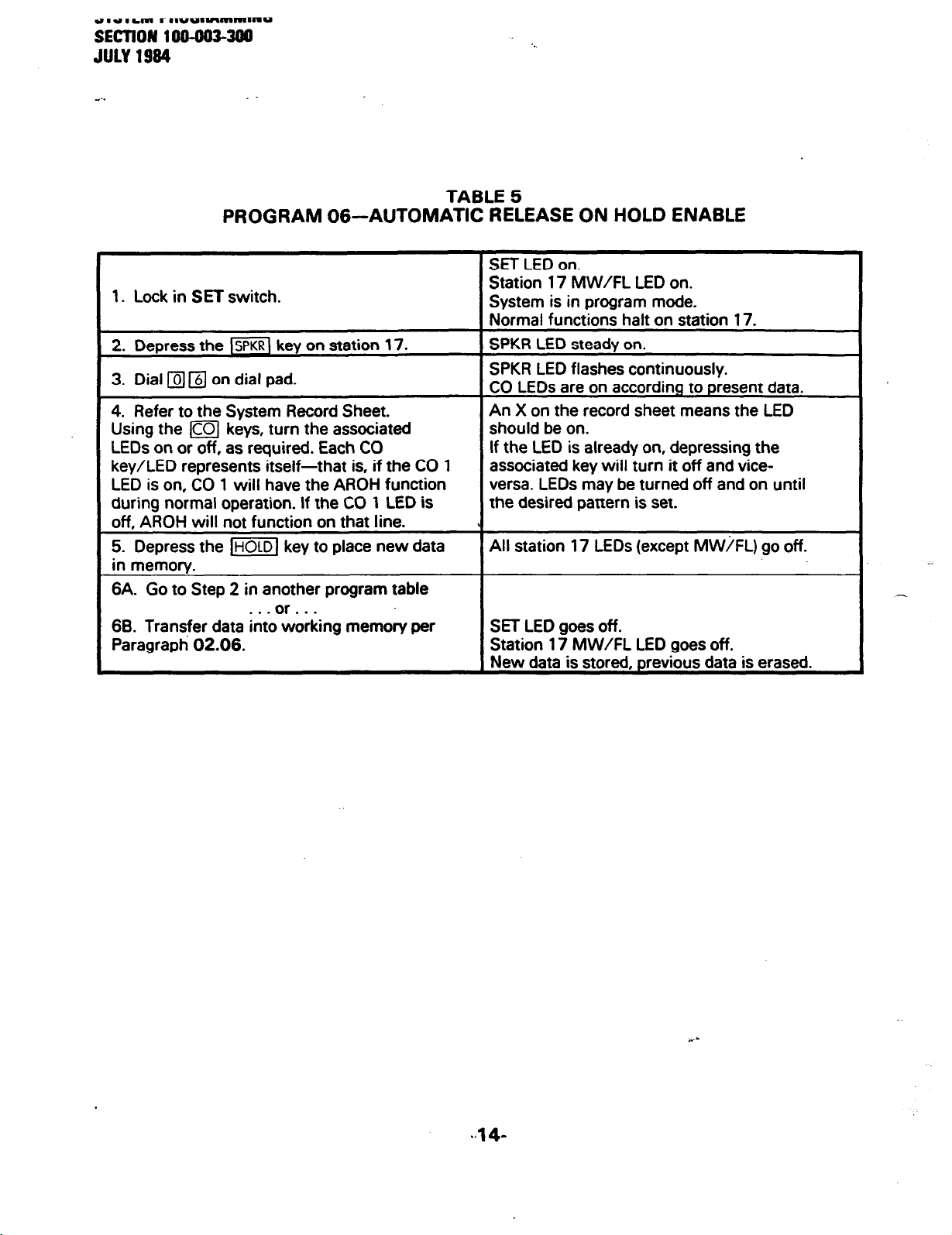
PROGRAM 06-AUTOMATIC RELEASE ON HOLD ENABLE
1. Lock in SET switch.
2.
Depress the
3. Dial
4. Refer to the System Record Sheet.
Using the m keys, turn the associated
LEDs on or off, as required. Each CO
key/LED represents itself-that is, if the CO 1
LED is on, CO 1 will have the AROH function
during normal operation. If the CO 1 LED is
off, AROH will not function on that line.
5. Depress the /=I key to place new data
in memory.
6A. Go to Step 2 in another program table
66. Transfer data into working memory per
Paragraph 02.06.
q q
lSPKR[
key on station 17.
on dial pad.
. . . or . . .
TABLE 5
SET LED on.
Station 17 MW/FL LED on.
System is in program mode.
Normal functions halt on station 17.
SPKR LED steady on.
SPKR LED flashes continuously.
CO LEDs are on according to present data.
An X on the record sheet means the LED
should be on.
If the LED is already on, depressing the
associated key will turn it off and viceversa. LEDs may be turned off and on until
the desired pattern is set.
All station 17 LEDs (except MW/FL) go off.
SET LED goes off.
Station 17 MW/FL LED goes off.
New data is stored, previous data is erased.
Page 68

PROGRAM 07-AUTOMATIC RELEASE ON HOLD TIMING
1. Lock in SET switch.
2. Depress the
3. Dial fl m on dial pad.
4. Refer to the System Record Sheet.
Using the m keys, turn the associated
LEDs on or off, as required. Each CO
key/LED represents itself-that is, if the CO 1
LED is on, CO 1 will use XB (cross-bar) timing
for AROH. If the CO 1 LED is off, ESS timing
will be used on that line.
5. Depress the /ml key to place new data
in memory.
6A. Go to Step 2 in another program table
6B. Trartsfer data into working memory per
Paragraph 02.06.
1 SPKRl
. . . or. . .
key on station 17.
SYSTEM PROGfWlMlNG
SECTION 1 OO-G03-300
JULY 1994
TABLE 6
SET LED on.
Station 17 MW/FL LED on.
System is in program mode.
Normal functions halt on station 17.
SPKR LED steadv on.
SPKR LED flashes continuously.
CO LEDs are on according to present data.
An X on the record sheet means the LED
should be on.
If the LED is already on, depressing the
associated key will turn it off and viceversa. LEDs may be turned off and on until
the desired pattern is set.
All station 17 LEDs (except MW/FL) go off.
SET LED goes off.
Station 17 MW/FL LED goes off.
New data is stored, previous data is erased.
NOTE:
Program 07 will have no meaning if AR0
-15-
i was rejected in Program 06.
Page 69

SYSTEM PROGIUWMING
SECTION 199-993-399
JULY 1994
v..
PROGRAM 1 0-PBX BACKUP
1. Lock in SET switch.
2. Depress the m key on station 17.
3. Dial /TJ q on dial pad.
4. Refer to the System Record Sheet.
Using the m keys, turn the associated
LEDs on or off, as required. Each CO
key/LED represents itself-that is, if the CO 1
LED is on; the system assumes that the CO 1
line is connected to a PBX line and will cause
features such as Toll Restriction and Auto-
matic Dialing to function accordingly.
5. Depress the 1-1 key to place new data
in memory.
6A. Go to Step 2 in another program table
. . . or . . .
68. Transfer data into working memory per
Paragraph 02.06.
i
TABLE 7
SET LED on.
Station 17 MW/FL LED on.
System is in program mode.
Normal functions halt on station 17.
SPKR LED steady on.
SPKR LED flashes continuously.
CO LEDs are on according to present data.
An X on the record sheet means the LED
should be on.
If the LED is already on, depressing the
associated key will turn it off and viceversa. LEDs may be turned off and on until
the desired pattern is set.
All station 17 LEDs (except MW/FL) go off. -
SET LED goes off.
Station 17 MW/FL LED goes off.
New data is stored, previous data is erased.
-16-
,. -
Page 70

e..
SYSTEM PROGRAMMING
SECTION 100-003-300
JULY 1984
TABLE 8
PROGRAM 1 X-PBX ACCESS CODES
. Lock in SET switch.
I q a (X = 1) to program first
q
(X = 2) to program second
two digits must be
0 If the access code is a single digit, enter
q
as the second digit.
l
If all combinations following a particular
first digit are to be considered access
codes (e.g. 91, 92, 93, etc.), depress
the (DNDI key for the second digit.
1. Depressing the q key displays the data without changing it. The first q willdispla y the first digit;
entered.)
ystem IS In program mode.
W/FL LED on.
X=LEDon
All LEDs off = no data
with this program
. ..or...
jB. Go to Step 2 in another program table
. . -or.. .
iC. Transfer data into working memory per
‘aragraph 02.06.
-17-
Page 71

SYSTEM PROGRAMMI#G
SECTION 100-003-390
JULY 1994
e..
. -
PROGRAM 20-TOLL RESTRICTION DISABLE
1. Lock in SET switch.
2. Depress the (SPKRI key on station 17.
3. Dial
4. Refer to the System Record Sheet.
Using the m keys, turn the associated
LEDs on or off, as required. Each CO
key/LED represents itself-that is, if the CO 1
LED is on, Toll Restriction will not function on
CO 1. If CO 1 LED is off, Toll Restriction will
function on CO 1 _ etc.
5. Depress the l=I key to place new data
in memory.
6A. Go to Step 2 in another program table
66. Transfer data into working memory per
Paragraph 02.06.
q q
on dial pad.
. . . or. . .
TABLE 9
SET LED on.
Station 17 MW/FL LED on.
System is in program mode.
Normal functions halt on station 17.
SPKR LED steadv on.
SPKR LED flashes continuously.
CO LEDs are on according to present data.
An X on the record sheet means the LED
should be on.
If the LED is already on, depressing the
associated key will turn it off and viceversa. LEDs may be turned off and on until
the desired pattern is set.
All station 17 LEDs (except MW/FL) go off..
SET LED goes off.
Station 17 MW/FL LED goes off.
New data is stored. previous data is erased.
:
Page 72

TABLE 10
PROGRAM 2X-TOLL RESTRICTION EXCEPTION CODES
1. Lock in SET switch.
2.
Depress the
3. Dial q a on the dial pad. X = 1,2,3,
ztc.-the system will store a maximum of five
ties. Dial 0111 (X = 1) to program first
exception code, q @ (X = 2) to program
second
4. Refer to the System Record Sheet. Using
:he dial pad, enter the required 4-digit excep:ion code (four digits must be entered).
exception code, etc.
l
ff less than four digits are used, enter
for remaining digits.
1 I I I
Kev/LED Start
AD4
L AD3
AD2
/SPKRl
Flash
key on station 17.
q
1st Digit
steady
SYSTEM PROGRAMMING
SECTION 199-993-399
SET LED on.
Station 17 MW/FL LED on.
System is in program mode.
Normal functions halt on station 17.
SPKR LED steady on.
SPKR LED flashes continuously.
AD 2 LED will flash.
INT, CO 1,2 & 3 LEDs will light to display
data in Binary format.
AD 2. 3 & 4 LEDs will light steadily to indi-
cate which digit is being displayed.
2nd Digit
Steady
I
3rd Digit
Steady
Steady
I
4th
steady
JUCY 1994
*
Dieii
, co3
I co2
. co1
INT Binary Data Binary Data Binary Data Binarv Data
NOTES:
1. Depressing the q key displays the data wtihout changing it The first
the second
AllLEDsoff=nodata
I memorv.
\ Return to Step 2 in order to continue
th this program
Go to Step 2 in another program table
Tran3er data into working memory per
lgraph 02.06.
q
will display the second dig& etc.
X=LEDon
. ..or...
. . .
data without ente
or...
Binatv Data Binary Data Binary Data Binary Data
Binary Data Binary Data
8inary Data Binary Data
SET LED goes off.
Station 17 MW/FL LED goes off.
Binary Data Binary Data
Binary Data Binary Data
will displa y the first
q
,. -
dig&-
Page 73

SYSTEM PROGfIAMYlNG
SECTION lW4G3400
JULY 1984
. -
PROGRAM SXX-STATION CO LINE ACCESS
1. Lock in SET switch.
2. Depress the
3. Dial mm @ on the dial pad. XX = the
number of the station(s) to be programmed.
l
Enter q n if all stations are to be
programmed simultaneously.
l
Enter q m if four lower numbered
stations (10 - 13) are to be programmed
simultaneously.
l
Enter j?jj (?l if four higher numbered
stations (14 - 17) are to be programmed
simultaneously.
4. Refer to the System Record Sheet. Using
the CO keys, turn their associated LEDs on or
off, as required.
0 LED on = Access allowed
l
Each CO key/LED represents itself-that
is, if the CO 1 LED is on, then the station
being programmed (XX) is allowed access
to CO 1, etc.
5. Depress the 1-1 key to place new data
in memory.
6A. Return to Step 2 in order to continue
with this program
1 SPKR
[ key on station 17.
TABLE 11
SET LED on.
Station 17 MW/FL LED on.
System is in program mode.
Normal functions halt on station 17.
SPKR LED steady on.
SPKR LED flashes continuously.
CO LEDs will be on according to present
data.
I
An X on the record sheet means the LED
should be on.
If the LED is already on, depressing its associated key will turn it off and vice-versa.
LEDs may be turned off and on until the
desired pattern is set.
All station 17 LEDs (except MW/FL) go off.
66. Go to Step 2 in’&%& program table
. . .
6C. Transfer data intoOCwwking memory per
Paragraph 02.06.
, .
SET LED goes off:
Station 17 MW/FL LED goes off.
New data is stored, previous data is erased.
,.--
-2o-
Page 74

- SECTION
PROGRAM 4XX-STATION TYPE and FLEXIBLE KEY ASSIGNMENT
1. Lock in SET switch.
2. Depress the
3. Dial 1’ rrrl Kl on the dial pad. XX = the
number of the station(s) to be programmed.
l
Enter Dm if all stations are to be programmed simultaneously.
l
Enter q I if four lower numbered stations (10 - 13) are to be programmed
simultaneously.
e Enter
tions (14 - 17) are to be programmed
simultaneously.
4. Refer to the System Record Sheet. Using
the INT and CO keys, turn their associated
LEDs on or off, as required.
The detailed meaning of each key is shown
below.
5. Depress the mj key to place new data
in memory.
6A. Return to Step 2 in order to continue
with this program
q q
1 SPKR
1 key on station 17.
if four higher numbered sta-
Key/LED. EKT TYPE”
co2
,COl -
INT #1 #l
SYSTEM PROGRAMMING
TABLE 12
SET LED on.
Station 17 MW/FL LED on.
System is in program mode.
Normal functions halt on station 17.
SPKR LED steady on.
SPKR LED flashes continuously.
INT & CO LEDs will be on according to
present data.
An X on the record sheet means the LED
should be on.
If the LED is already on, depressing its as-
sociated key will turn it off and vice-versa. -
LEDs may be turned off and on until the
desired pattern is set.
1 O-key 20-key
#2 #3
#2
All station 17 LEDs (except MW/FL) go off.
100-003-300
JULY 1984
.
“See Figure 1
6B. Go to Step 2 in.ar%er program table
. . . or. . .
6C. Transfer data into working memory per
Paragraph 02.06.
SET LED goes off.
Station 17 MW/FL LED goes off.
New data is stored, previous data is erased.
..-
-21-
Page 75

SYSTEM PROGRAMMING ‘..
SECTION 199-093-390
JULY 1994
e..
TABLE 13
PROGRAM SXX-STATION CLASS OF SERVICE
1. Lock in SET switch.
all stations are to be
if four lower numbered sta-
- 13) are to be programmed
simultaneously.
l
Enter q m if four higher numbered sta-
tions (14 -
ciated LEDs on or off, as required.
The detailed meaning of each key is shown
below.
17) are to be programmed
and AD keys, turn their
pro-
asso-
should be on.
If the LED is already on, depressing its associated key will turn it off and vice-versa.
LEDs may be turned off and on until the
or. . .
6B. Go to Step 2 in’another program table
. . . or . . .
6C. Transfer data into working memory per
Paragraph 02.06.
/FL LED goes off.
red, previous data is erased.
,. -
-22-
Page 76

‘.
SYSTEM PROGRAMMI#G
SECTlON100-003-300
TABLE 14
PROGRAM GXX-TOLL RESTRICTION CLASSIFICATION
JULY 1994
1. Lock in SET switch.
number of the station(s) to be programmed.
l
Enter q j?jJ if all stations are to be programmed simultaneously.
l
Enter a/-i-J if four lower numbered stations (10 - 13) are to be programmed
simultaneously.
l
Enter ]a p) if four higher numbered sta-
. .
D keys, turn their asso-
W/FL LED on.
IS already on, depressing its
as-
this program
with
66. Go to Step 2 in’ar$her program table
6C. Transfer data into working memory per
Paragraph 02.06.
-23-
Page 77

SYSTEM PROGRAMMING
SECTION 199-993-399
JULY 1994
v..
PROGRAM 7XX-STATION OUTGOING CALL RESTRICTION
1. Lock in SET switch.
2. Depress the
3. Dial 17 fl Kl on the dial pad. XX = the
number of the station(s) to be programmed.
l
Enter /?jJa if all stations are to be
programmed simultaneously.
l
Enter q j-iJ if four lower numbered
stations (10 - 13) are to be programmed
simultaneously.
l
Enter m m if four higher numbered
stations (14 - 17) are to be programmed
simultaneously.
4. Refer to the System Record Sheet. Using
the CO keys, turn their associated LEDs on or
off, as required.
* LED on = Restricted outgoing calls.
l
Each CO key/LED represents itself-that
is, if the CO 1 LED is on, then the station
being programmed (XX) is restricted from
outgoing calls on CO 1, etc.
5. Depress the [‘I key to place new data
in memory.
6A. Return to Step 2 in order to continue
with this program
ISPKR]
key on station 17.
TABLE 15
SET LED on.
Station 17 MW/FL LED on.
System is in program mode.
Normal functions halt on station 17.
SPKR LED steady on.
SPKR LED flashes continuously.
CO LEDs will be on according to present
data.
’
.
An X on the record sheet means the LED
should be on.
If the LED is already on, depressing its associated key will turn it off and vice-versa.
LEDs may be turned off and on until the
desired pattern is set.
All station 17 LEDs (except MW/FL) go off.
68. Go to Step 2 in’igthei program table
. . . or. . .
6C. Transfer data into working memory per
Paragraph 02.06.
SET LED goes off.
Station 17 MW/FL LED goes off.
New data is stored, previous data is erased.
. . -
-24-
Page 78

w..
PROGRAM 8xX-CO RINGING ASSIGNMENTS-DAY
1. Lock in SET switch.
2.
Depress the
3. Dial mm m on the dial pad.* XX = the
number of the station(s) to be programmed.
0 Enter q a if all stations are to be
programmed simultaneously.
l
Enter q m if four lower numbered
stations (10 - 13) are to be programmed
simultaneously.
l
Enter m m if four higher numbered
stations (14 - 17) are to be programmed
simultaneously.
4. Refer to the System Record Sheet. Using
the CO keys, turn their associated LEDs on or
off, as required.
l
LED on = Ring in
0 Each CO key/LED represents itself-that
is, if the CO 1 LED is on, then the station
being programmed (XX) will ring when a
call comes in on CO 1 in
5. Depress the m) key to place new data
in memory.
6A. Return to Step 2 in order to continue
with this program
ISPKR
1 key on station 17.
DAY
mode.
DAY
SYSTEM PROGRAMMING
SECTION 100-003-300
JULY 1994
TABLE 16
SET LED on.
Station 17 MW/FL LED on.
System is in program mode.
Normal functions halt on station 17.
SPKR LED steady on.
SPKR LED flashes continuously.
CO LEDs will be on according to present
data.
An X on the record sheet means the LED
should be on.
If the LED is already on, depressing its associated key will turn it off and vice-versa.
LEDs may be turned off and on until the
desired pattern is set.
mode.
All station 17 LEDs (except MW/FL) go off.
6B. Go to Step 2 in.ar%her program table
. . . or...
6C. Transfer data into working memory per
Paragraph 02.06
SET LED goes off.
Station 17 MW/FL LED goes off.
New data is stored, previous data is erased.
NOTE:
Station(s) being designated to ring must be allowed access by Program 3XX.
-25-
,.-
Page 79

SYSTEM PROGRAMMING
SECTION 100-003-300
JULY 1994
PROGRAM 9xX-CO RINGING ASSIGiVMENTS-NITE
1. Lock in SET switch.
2. Depress the m key on station 17.
3. Dial jq rjil rjil on the dial pad.* XX = the
number of the station(s) to be programmed.
l
Enter q m if all stations are to be
programmed simultaneously.
l
Enter q a if four lower numbered
stations (10 - 13) are to be programmed
simultaneously.
l
Enter m Tz] if four higher numbered
stations (14 - 17) are to be programmed
simultaneously.
4. Refer to the System Record Sheet. Using
the CO keys, turn their associated LEDs on or
off, as required.
l
LED on = Ring in
l
Each CO key/LED represents itself-that
is, if the CO 1 LED is on, then the station
being programmed (XX) will ring when a
call comes in on CO 1 in
5. Depress the [mj key to place new data
in memory.
6A. Return to Step 2 in order to continue
with this program
NITE
mode.
NITE
mode.
TABLE 17
SET LED on.
Station 17 MW/FL LED on.
System is in program mode.
Normal functions halt on station 17.
SPKR LED steady on.
SPKR LED flashes continuously.
CO LEDs will be on according to present
data.
An X on the record sheet means the LED
should be on.
If the LED is already on, depressing its associated key will turn it off and vice-versa.
LEDs may be turned off and on until the
desired pattern is set.
All station 17 LEDs (except MW/FL) go off.
6B. Go to Step 2 in’ar%er program table
. ..or...
6C. Transfer data into working memory per
Paragraph 02.06.
SET LED goes off.
Station 17 MW/FL LED goes off.
New data is stored, previous data is erased.
NOTE:
Station&) being designated to ring must be al/owed access by Program 3XX.
-26-
Page 80

SYSTEM PROGRAMMING
JULY 1984 .
M..
Strata s”
SYSTEM RECORD SHEET
PROGRAM 01 -SYSTEM ASSIGNMENTS
X = Select (LED on) Initialized Data: AD 4 LED on; all other LEDsoff
NOTE:
Only one Message Center is permitter2 if both stations 10 and ? 1
are chosen as Message Centers, station 10 will have priority.
PROGRAM 05
AUTOMATIC RECALL FROM HOLD TIMING
KEY/LED X
AD4 ’ 18oseconds
AD3 128 Seconds
AD2
AD1
co3 48 Seconds
co2
co i 18 Seconds
INT
X = Select (LED on)
Initialized Data: 32 Seconds
TIME
98 Seconds
84 !%cm&
32 !Seconds
No Recall
CO LINE OPTIONS
PROGRAM 06 PROGRAM 07
AUTOMATIC RELEASE AUTOMATIC RELEASE
ON HOLD ENABLE ON HOLD TIMING
X = Enable (LED on)
initialized Data:
All LEDs off
-l-
X =X6 (LED on) ,..
Initialized Data:
All LEDs off
SAS-lW-OD3 lOM-l-85
Page 81

SYSTEM PROGRAMMING
JULY 1994
PROGRAM lo-PBX BACKUP
\
KEY/LED X
co3
co2
co1
X = Connected to PBX line (LED on)
Initialized Date: All LEDs off
PROGRAM 1X-PBX ACCESS CODES
CODE
#l(ll)
#2(12)
#3(131
#4(14)
#5(15)
#6(16)
#7(17)
#a(181
Enter Access Codes (maximum: 8)
Initialized Data: None
NOTE:
If the access code is a single dig& enter
s’*Os in the second column. If all
combinations following a particular first digit are to be considered access
codes (e.g., 91,92,93, etc.J, enter “D” (do not careJ in the second column.
PROGRAM 20-TOLL RESTRICTION DISABLE
KEY/LED X
co3
co2
CO1
X = Disable (LED on) X = Disable (LED on)
Initialized Data: All LEDs Initialized Data: All LEDs
Off
PROGRAM 2X-TOLL RESTRICTION EXCEPTION CODES
.
Enter actual Exception Codes (maximum: 5)
Initialized Data: None
NOTE:
If codes are fess than four dig& enter -*- in the remaining spa&.
-2-
Page 82

‘.
PROGRAM 3XX-STATlON CO UNE ACCESS
SYSTEM PRUGNAMMlNG
JULY 1986
X = Select (LED on)
Initialized Data: All LEDs on
PROGRAM 4XX-STATION TYPE and FLEXIBLE KEY ASSIGNMENT
(See Fiiure 1)
X = Select (LED on)
Initialized Data: INT LED on; all other LEDs off
PROGRAM 5XX-STATION CLASS OF SERVICE
.
I
X = Select (LED onj Initialized Data: COs 3 & 1 & INT LEDs on; other LEDs off
I
IIlIIIIlJ
PROGRAM GXX-TOLL RESTRICTION CLASSIFICATION
X = Select (LED on) Initialized Data: No Restriction
Page 83

SYSTEM PROGRAlWMlNG
JULY 1984
‘.
e..
PROGRAM 7XX-STATION OUTGOING
KEY/LED
co3
co2
CO1
FEATURE
ReNliued
Restriclad
Restriuad
CALL RESTRICTION
STATION NUMBWS _
10 11 12 13 14 1116Y7
X = Select (LED on) Initialized Data: All LEDs off
PROGRAM SXX-CO RINGING ASSIGNMENTS-DAY
X = Select (LED on)
Initialized Data: Station ID-all LEDs on; all others off
PROGRAM 9xX-CO RINGING ASSIGNMENTS-NITE
X = Select (LED on)
1
Initialized Data: Station 1 l-all LEDs on; all others off
,. -
Page 84

TOSHBA SYSTEM PRACTICES
ELECTRONIC KEY TELEPHONE SYSTEM
Strata S
OPERATING PROCEDURES
SECTION 100-003-49D
JULY 1994
OPERATING PROCEDURES
.
Page 85

TOSHIBA SYSTEM PfWTiCES
ELECTRONIC KEY TELEPHONE SYSTEM
m..
-
OPERATING PROCEDURES
SECTION 100-00340
JULY 1984
Strata S
OPERATING PROCEDURES
TABLE of CONTENTS
PARAGRAPH
TABLE of CONTENTS
01
02
02.00.0
03
03.00.0
03.01 .o
04
05
05.00.0
05.01 .o
06
06.00.0
06.01 .O
06.02.0
06.03.0
06.04.0
06.05.0
06.06.0
06.07.0
06.08.0
06.09.0
06.10.0
. 06.11.0
06.12.0
07
07.00.0
07.10.0
07.20.0
07.30.0
07.40.0
07.50.0
INTRODUCTION
KEY FUNCTIONS
VOLUME CONTROLS ........................
TONE & LED ILLUMINATING INdlCATldN’S. : : : : : : : : : : : : : : :
MESSAGE WAITING .........................
TABLE A-Telephone Tones
OPERATING PROCEDURES
SUBJECT
........................
...........................
..........................
Standard Key Functions
1 O-key “S” EKT .........................
Optional EKTs
Message Center .........................
Called Station .................
Outside Calls
Intercom Calls
Call Holding
Call Transfer
Night Transfer
Conferencing
Automatic Dialing
On-hook Dialing .........................
Handsfree Monitoring .......................
Group Listening .........................
Paging .............................
Override ............................
Do Not Disturb ..........................
Strata SOPTIONS
lo-key EKT ...........................
BLF lo-key EKT .........................
20-key EKT ...........................
Special Key Functions
Automatic Dialing with Special Keys
Speakerphone ..........................
........................ : .
..........................
...........................
...........................
...........................
..........................
......................
.......................
.......................
........................
........................
......................
................
; ........
PAGE
i
1
1
1
1 ’
1
1 :
1
2
2
2
2
2
2’.
2
3
3
3
4
5
7
7
7
7
7
8
8
8
8
8
8
8
9
-i-
,. -
Page 86

P
OPERATING PROCEDURES
SECTlOW lOO40340
e..
01
INfitODUCTlOfi
03 VOLUME CONTROLS
JULY 1984
01 .OO.l The operations of the various Struts
S electronic key telephones (EKT) will be
des-
cribed in this section. These EKTs are specially
designed telephones
and
are connected to the
system using industry standard 2-pair wiring.
02 KEY FUNCTIONS
02.00.0 Standard Key Functions
02.00.1 The standard Strata S EKT has
either 13 or 14 line and feature keys and a push-
button dial pad. The following is a general descrip-
tion of each key.
CENTRAL OFFICE UNE KEY m
Accesses an outside line.
INTERCOM KEY m
Accesses the intercom line.
DO NOT DISTURB KEY m
Locks the individual EKT into the Do Not Dis-
turb mode.
MESSAGE WAITING & FLASH KEY 1-1
Used by station 10 or 11 (operator) to indicate
when a message is waiting for any other station. When used as a Flash Key, it disconnects
and recalls dial tone on a CO line, or is used to
access PBX features.
SPEAKER KEY m
Turns the speaker ON/OFF.
MICROPHONE KEY m
(Speakerphone EKTs only)
Cuts off the Speakerphone’s microphone for
private conversations. This key is labeled
“MUTE” on some EKTs.
CONFERENCE KEY 1-1
Sets up conference calls.
HOLD KEY mj
Places an outside call on hold.
NIGHT TRANSFER m
Takes the place of the m] key on the opera-
tor’s station and is used to control the system’s
CO/PBX line ringing pattern.
AUTOMATJC DIALING KEYS m
Single-key automatic dialing for telephone
numbers after accessing a CO line.
03.00.0 1 O-key “S” EKT
03.00.1 The dial tone volume level on the
standard 1 O-key “S” EKT is controlled by the sliding volume control located on the faceplate of the
telephone. A 3-position switch on the bottom of
the EKT adjusts the ring tone and intercom voice-
announcement volume.
03.01 .O Optional EKTs
03.01 .l The voice and ring tone volume levels
on the optional EKTs are controlled by separate
volume controls located on the rear of each telephone. The control on the right adjusts speaker
volume for dial tone and voice level; the left control
adjusts ring tone and intercom voice-announce-
ment volume.
04 TONE & LED
ILLUMINATING INDICATIONS
I-Use:
A steady-double flash rate(2.0 secondson-%
second off-% second on--‘/e second off) indicates the CO line presently in use at the EKT
that originated the call. Other stations’.LEDs
will be steady-on for that line.
I-Called:
A pulsating on/off flash rate (10 impulses per
second (IPS) for 1 second on and 1 second off)
will appear on the INT LED at the EKT being
called.
I-Hold:
A fast (4 IPS) flash rate (H second on--‘/s
second off) indicates the CO line placed on
hold at that EKT. The LEDs of the CO line on
hold will flash at a medium rate (W second
on-% second off) at the other stations.
Hold Recall:
Aquickflash rate matching the tones (2 IPS for
1 second-10 IPS for 1 second) will remind a
station which line has been on hold for the
programmed period of time.
Conference:
A very fast flash rate (10 IPS) indicates the CO
line presently in the Conference mode. Other
stations’ LEDs will show the same indication
for that line.
+=-
.
NOTE CO Incoming Call:
See Paragraph 07 for a fullexplanation of the
A slow flash rate (W second on--U second off)
features of the optional EKTs. indicates which CO line has an incoming call.
-l-
Page 87

OPERATING PROCEDURES
SECTION 100-003-400
JULY 1994
-
05 MESSAGE WAITING
0500.0 Message
Station 10 or 11 on&
0500.1 To use Message Waiting
1) Call the appropriate station on intercom. _ _
2) If no answer, depress the IMW/FI] key on the
Message Center EKT.
l
This illuminates the MW/FL LEDs on
both EKTs.
3) Hang up.
l
This extinguishes the Message Center
MW/FL LED (LED on called station re-
mains lit).
05.00.2 To clear the MW/FL LED on the called
EKT from the Message Center
Center
TELEPHONE TONES
Ringing
Ring-back
Intercom Dial Tone
Busy Tone
Do Not Disturb Tone
Busy & DND Override Tone
Voice Page Warning Tone
Executive Override Warning Tone
Hold Recall
Tone
CO tine (idle station)
(busy station)
Intercom tine
Tone
1) Call the appropriate station.
2) Depress the jMw/FLI key twice. .
05.01 .O Called Station
05.01
1) Lift the’handset.
2) Call the Message Center on the intercom.
3) After receiving the message(s), hang up.
05.01.2 To clear the MW/FL LED from the
called station
1) Lift the handset (without depressing the
2) Depress the (Mw/FIl key.
3)) Hang up.
.l
To use Message Waiting
intercom or a CO/PBX key).
TABLE A
‘8 600 Hz/800 Hz, modulated by 16 Hz, 1 second
on, 3 seconds off
2400 Hz, modulated by 10 Hz, 1 second on, 3
seconds off
600 Hz. 1 second on, 3 seconds off
600 Hz, 1 second on, 3 seconds off
600 Hz, continuous
600 Hz, 0.25 second on, 0.25 second off
600 Hz, 0.12 second on, 0.12 second off
2400
Hz, 1 second on, 3 seconds off
600 Hz, 1 second on only (via EKT speaker)
600 Hz, 0.5 second on only (via handset)
2400 Hz, modulated by 10 Hz-l second on, 1
second off
-
06 OPERATING PROCEDURES
06.00.0 Outside Calls
06.00.1 To make an outside call (off-hook
dialing)
1) Lift the handset.
2) Depress an available CO key.
l
Listen for dial tone.
l
CO line LED will flash at the l-use rate.
3) Dial the desired telephone number.
4) Hang up when the call is completed.
06.00.2 To receive an incoming call
1) You will hear a CO incoming call ringing tone.
l
The CO line LED will flash at the CO
incoming call rate.
2) Lift the handset.
l
CO line LED will flash at the l-use
3) Hang up when the call is completed.
06.01 .O Intercom Calls
06.01.1
1) Lift the handset.
2) Depress the m key.
-2-
To make an int_e_rcm call
l
You will hear intercom dial tone.
l
INT LED will flash at the l-use rate.
rate.
Page 88

v..
3) Dial the desiredstation. .
8 You will hear a single ring tone.
4) Speak when the ring tone ends.
5) Hang up when the call is completed.
NOTE:
Tone signalling is accomplished by dialing
q
aher the station number. An intercom call
may be answered a? any station.
OPERATING PROCEDURES
SECTION lOMO3499
JULY 1984
2)
Depress the m key.
8 You will hear intercom dial tone..
8 The INT LED will flash at the l-use rate.
3)
Dial the desired station number.
4A) If you hear a single ring tone, announce the
call (noting the correct CO line), and hang up.
8 The CO line LED will flash at the l-hold
rate until the other station connects with
the call.
06.01.2 To receive an intercom call
1) You will hear a single long tone, followed by
the caller’s voice.
8 The INT LED will flash at the l-called rate.
2) Lift the handset.
8 The INT LED will flash at the l-use rate.
3) Hang up when the call is completed.
06.01.3 Intercom tone signalling (program-
mable option)
1) You will hear a ringing tone as the primary
method of intercom call signalling.
8 Handsfree answerback is inoperative.
2) A voice call can be accomplished by dialing
III.
06.02.0 Call Holding
06.02.1 To hold a call
While connected to an outside call, depress the
[Holo1 key.
8 The CO line LED will flash at the l-hold rate.
NOTES:
1.
When a CO line is placed on hold If may
be picked up
An on-hold reminder tone is generated
2.
wirhin a pre-determined time at the sta-
tion that placed the line on hold The LED
flash rate of the recalling line will synchronize with tone.
Hold is automatically released if the other
3.
party hangs up.
06.03.0
06.03.1
1) While connected to an outside call, depress
the IHOlD key.
Call Transfer
To transfer a call
8 The CO line LED will flash at the l-hold
rate.
at
any station.
4B) If the station is busy, you have several
choices:
a) If you are the Message Center, depress
the /ml
b) Depress the appropriate m key and
inform the caller of the situation.
c) Dial q for busy override (see Override).
NOTES:
1.
When a CO line is placed on hold it may
be picked up at any station.
2.
An on-hold reminder tone is generated
within a pre-determined time at the station that placed the line on hold. The LED
flash rate of the recalling ljne will synchronize with tone.
3.
Hold is automatically released if the other
party hangs up.
06.03.2
1) You will hear a single long tone, followed by
2)
3) Depress the announced m key.
06.04.0 Night Transfer
Programmable option for station IO only.
06.04.1
Depress the m key.
8 The NT LED illuminates.
8 All incoming calls are automatically trans-
ferred to the preselected stations.
06.04.2
Return the system to the normal ringing pattern by
depressing the m key again.
8 NT LED extinguishes.
To receive a transferred call.
an announcement.
8 The INT LED will flash at the l-called rate.
Lift the handset and acknowledge the an-
nouncement.
8 You are now connected with the outside
call.
To initiate Night Transfer
To
cancel Niglit Transfer
key.
-3-
Page 89

OPERATlNG PROCEDURES
SECTION 100-003-400
itulY 1994
06.05 .O Conferencing
06.05.1 To conference one station and two
CO lines
Lift the handset.
1)
Depress any available a key.
2)
Dial the desired telephone number.
3)
Depress the Iml key after the called party
4)
answers.
Depress a second available m key.
5)
Dial the second party’s telephone number.
6)
Depress the ml key after the second
7)
party answers.
Depress the
8)
l
Station is now connected to both CO
lines.
Hang up when the conference call is com-
9)
pleted.
06.052 To conference two or three stations
and two CO lines
Lift the handset.
1)
Depress any available m key.
2)
Dial the desired telephone number.
3)
Depress the l=I key after the called party
4)
answers.
Depress a second available m key.
5)
Dial the second party’s telephone number.
6)
Depress the I=] key after the second
7)
party answers.
Depress the IINT] key, and call the station(s)
8)
to be included in the conference call.
Advise the station(s) of the number of the
9)
second CO line and tell them
m key when its LED begins the distinctive
conference flash.
10) Depress the second a key.
11) Depress the 1-1 key.
l
CO LED changes to conference flash.
l
CO LED changes l-use rate when the
other station enters the conference.
original [col
key.
to
_
depress that
13) After the station(s) are entered, depress the ‘.
1-1 key, and then the first a key.
14) Hang up when the conference call is
completed.
06.053 To conference up to four stations and
one CO line
Lift the handset.
1)
Depress any available m key.
2)
Dial the desired telephone number.
3)
Depress the ml key after the called party
4)
answers.
Depress the m key, and call the station(s)
5)
to be included in the conference call.
Advise the station(s) of the number of the CO
6)
line and tell them to depress that a key
when its LED begins the distinctive conference flash.
Depress the m key. . -
7)
Depress the 1-1 key.
8)
0 CO LED changes to conference flash.
l
CO LED then changes to l-use rate when
the other station enters the conference.
Depress the 1-1 key again if a third sta-
9)
tion is to enter the conference call.
10) Repeat for a fourth station, if necessary.
11) Hang up when the conference call is
completed.
06.05.4 To conference three or four stations on
intercom
1) Using the intercom, advise the third and
fourth parties of the conference. Tell them to
depress the m key when its LED begins the
distinctive conference flash.
2) Using the intercom, call party #2.
3) Depress the ICoNF] key.
l
The LED changes to conference flash at
all stations.
l
The LED changes to l-use rate when the
third station enters the conference.
4) Depress the lmi key again to allow a
fourth party to enter.
.-
12) Depress the 1-1 key again if a third station i, to enter the conference call.
5) Hang up when the conference call is
completed.
-4-
Page 90

1-
OPERMING PROCEDURES
SECTION 100-0034W1
JULY 1984
Lift the handset.
06.06.0 Automatic Dialing
1)
06.06.1 To dial a frequently called number
automatically
NO JE:
See Paragraph 07.04.0 for optional key
usage.
A) Using the q key.
1) Lii the handset.
2) Depress any available m key.
l
Listen for dial tone.
3) Depress the q key.
4) Dial the 2-digit address code that corresponds to the desired telephone number.
l
Strata Swill automatically dial the
number for you.
5) Hang up when the call is completed.
B) Using an m key.
Lii the handset.
1)
Depress any available m key.
2)
l
Listen for dial tone.
Depress the m key that corresponds to
3)
the desired telephone number.
l Strata
Swill automatically dial the
number for you.
Depress any available m key.
2)
l
Listen for dial tone.
Depress the q key.
3)
Dial the 2-digit address code that corres-
4)
ponds to the first telephone number to be
dialed.
NO JE:
It is not necessary to wait until the system
has finished dialing to proceed with the fol-
lo wing steps.
5) Depress the q key again.
6) Dial the 2-digit address code that corresponds to the second telephone number to
be dialed.
7) Repeat the above steps for each subsequent number to be dialed.
l
Strata Swill automatically dial the
numbers for you.
8) Hang up when the call is completed.
B) Using an m key.
Lii the handset.
1)
Depress any available m key.
2)
l
Listen for dial tone.
Hang up when the callis completed.
4)
06.06.2
To automatically redial the last number
called
NO JE:
See Paragraph 07.04.0 for optional key
usage.
1) Depress any available m key.
l
Listen for dial tone.
2) Depress the q key.
l Strata
S will automatically dial the
last telephone number that was dialed at
that station.
3) Hang up when the call is completed.
06.06.3 To chain dial automatically
Automatically dials two or more sets of numbers
during one call. For use with long distance routing.
A) Using the q key.
Depress the m key that corresponds to
3)
the first telephone number to be dialed.
Depress the m key that corresponds to
4)
the second telephone number to be dialed.
Repeat the above-steps for each subse-
5)
quent number to be dialed.
l Strata
Swill automatically dial the
numbers for you.
Hang up when the call is completed.
6)
NO JE:
Telephone
numbers within the chain dial
sequence can be dialed via m keys or q +
a-digit address codes interchangeably. Only
the first number dialed during the chain dial
will be repeated
however.
by the automatic redial.
,. -
06.06.4 To store telephone numbers.
Telephone
numbers can be stored in the
memory by station 10 only.
-5-
system
Page 91

.I -; .
:
‘-- OPERATING PROCEDURES
SECTION 10&00340
JULY 1994 -
1) Remove the handset from its hook (do not
activate the intercom .or a CO line).
2) Depress the q and q k&s, respectively.
3) Dial a 2-digit address code.
l
Codes run consecutively from 60 through
99.
4) Dial the telephone number (up to 16 digits) to
be stored.
NOTE FOR BEHIND PBX:
It may be necessary to insert a pause after the
trunk access code to
allow
for dial tone delay.
Depress the [ml key (if the pause is
required) after entering the PBX access code.
5) Depress the q key to record the number in
memory.
6) Repeat the above steps with every number,
up to 40, to be stored.
7) Return the handset to on-hook.
8) Write down the address codes and numbers
for future reference.
NOTE:
Repeat this procedure to replace the stored
telephone numbers with new numbers.
06.06.6 To store a telephone number in station
memory
Ten telephone numbers may be stored by each
station.
A) Repertory dialing using the a key.
Lift the handset (do not activate the inter-
1)
com or a CO line).
Depress the m and a keys, respectively.
2)
Dial a 2-digit address code.
3)
l
Codes run consecutively 10 - 19.
6) Repeat the above steps with every number
(up to 10) to be stored.
7) Return the handset to on-hook. .
8) Write down the address codes and numbers
for future reference.
NOTE:
Repeat this procedure to replace the stored
telephone numbers with new numbers.
6) One-key automatic dialing using the m keys.
1) Lift the handset (do not activate the intercom or a CO line).
2) Depress the q key.
3) Depress one of the IAD keys.
4) Dial the telephone number(up to 16 digits)
to be stored.
NOTES:
1.
Each AD key actually uses one of the
station memory address codes ( jml) =
10, m2] = 1 I, etc.). .
2.
fFOR BEHIND PBX)-It ma y be necessary*
to insert a pause after the trunk access
code to allow for dial tone delay. Depress
the IMW/FLI key (if the pause is required)
after entering the PBX access code.
Depress the@ key to record the number in
5)
memory.
Repeat the above steps with every number
6)
to be stored.
Return the handset to on-hook.
7)
Write down the address codesand numbers
8)
for future reference.
NOTE: Repeat this procedure to replace the
stored telephone numbers with new numbers.
Dial the telephone number (up to 16 digits)
4)
to be stored.
NOTE FOR BEHIND P0X:
It may be necessary to insert a pause after the
trunk access code to allow for dial tone delay.
Depress the [hnw/FI] key (if the pause is
required) after entering the P8X access code.
5) Depress the@ key to record the number in
memory.
06.06.7 TO output q and q tones
When the special q or q tones must be output
(for computer input service or other use), the
Automatic Dialing feature must be disabled to
permit manual dialing of the a and m tones.
,.-A
Depress any available m
1)
key.
2) Dial any desired telephone number (either
manually or by utilizing the Automatic Dialing feature in the usual manner).
-6-
Page 92

‘.
OPEfWlNG PROCEDURES
SECTION 19940349
JULY 1994
-3) To disable the -Automatic Dialing feature,
thereby permitting the
q
and q tones to
output manually, first press the q key and
then the q key.
NOTE: NOTE:
Manual dialing only will be possible and the Manual dialing only will be possible and the
special q and q tones, as well as digits
special q and q tones, as well as digits
q
q
mm. will be output as dialed. The Automatic mm. will be output as dialed. The Automatic
Dizihg feature &llberestoredwhentheEKT
is hung up. or the CO line is placed on hold.
06.07.0 On-hook Dialing
Non-speakerphone models-see Paragraph 07
for speakerphone model EK Ts.
06.07.1 To make an outside call
1) Leave the handset on-hook.
2) Depress any available m key.
l
Listen for dial tone.
l
CO LED will flash at the l-use rate.
3) Dial the desired telephone number.
4) Lift the handset when the distant party
answers.*
4) Lii the handset to continue the conversation
when the distant party returns.
06.09.0 Group Listening
The group listening feature allows all persons
present to hear the distant party’s responses.
Depress and hold the IsPKRl key.
l
SPKR LED lights and distant party’s voice is
heard via the EKT’s speaker (handset is offhook but inoperative).
When local response is required:
l
Release the m key.
l
SPKR LED goes
l
EKT speaker is silenced.
l
Handset is activated.
off.
Repeat as required.
06.10.0 Paging
06.10.1 To page
1) Lift the handset.
2) Depress the m key and dial
q
for all
speakers(EKT and external).’ - --
5) Hang up when the call is completed.
06.07.2 To make an intercom call
1) Leave the handset on-hook.
2) Depress the m key.
0 INT LED will flash at the l-use rate.
3) Dial the desired station number.
l
You will hear a single ring tone.*
4) Lift the handset to converse.
5) Hang up when the call is completed.
*If busy tone is heard, depress the
pl key
to disconnect.
.06.08.0 Handsfree Monitoring
See Speakerphone for speakerphone model EK Ts.
Calls placed on hold by the distant party may be
monitored “Handsfree.”
1) Depress and hold the lwj key.
2) Place the handset on-hook.
3) Release the I=] key.
l
Sounds from the distant party will be
heard via the EKT’s speaker.
3) Make your announcement twice in a normal
voice level.
4) Hang up.
06.11 .O Override
06.11 .l To initiate a busy override signal
After reaching a busy station, you may signal that
station that a call is waiting by dialing m.
l
A tone signal will be heard at the busy station-
06.11.2 To override DND (programmable option)
After reaching a DND station, you may signal that
station that a call is waiting by dialing q .
l
A tone signal will be heard at the DND station.
06.11.3 To use executive override (programmable option)
Overrides the CO line and intercom privacy feature, and is able to enter any existing conversation
within the system. Only two stations can be pro-
grammed for this feature.
You may enter any conversation on any CO/PBX -.
line or the intercom by &pressing the appropriate
key.
l
A warning tone, however, is sounded before
the overriding station is actually connected.
.
-7-
Page 93

OPERATJNG PROCEDURES
SECTION 106-693469
JULY 1994
w..
-
06.12.0 Do Not Disturb
06.12.1
Depress the ml key.
0 DND LED will light steady.
06.12.2 To release Do Not Disturb
Depress the jml key.
l
DND LED will go off.
07.00.0 1 O-key EKT
07.00.1 The optional lo-key EKT, in initialized
mode, is equipped with 14 line and feature keys
including three CO keys, an intercom key, (DNDI,
and I-1 keys are not equipped with LEDs
(however, the AD LEDs do not operate). See Para-
graph 07.30.0 for details of the programmable
special feature keys.
07.10.0 BLF 1 O-key EKT
07.10.1 The optional BLF lo-key EKT has an
LED panel showing the busy/idle status of each
station. A station in the DND mode will show as
busy.
07.20.0 20-key EKT
To engage the Do Not Disturb mode
07 Strata
S OPTIONS
ALL CALL KEY m
Causes an All Call page throughout the system
(including both EKT and external speakers) if
depressed while the intercom line is idle.‘
DIRECT STATION SELECTION (DSS) KEYS
110-171
Each DSS key corresponds to the intercom numbers of the respective EKTs. The LEDs on these
keys indicate the busy lamp field. When the intercom line is not busy (the station LED is not lit),
depressing a DSS key assigned to an EKT which is
neither busy nor in DND will ring the station.
07.40.0 Automatic Dialing with Special Keys
07.40.1 To dial a frequently called number
automatically
Telephone numbers can be dialedb y either an m
or by using the m key and a 2-digit address
code in the usual
Strata
S manner.
1) Lift the handset.
2) Depress any available m key.
l
Listen for dial tone.
*
3) Depress the m key and dial the 2-digit
address code corresponding to the desired -
telephone number.
l Strata
S will automatically dial the
number for you.
07.20.1 The optional executive telephone (20-
key EKT) provides, in initialized mode (via ten additional feature keys), all keys mentioned above in
the 1 O-key description, plus 10 DSS keys.
07.30.0 Special Key Functions
07.30.1 Each EKT may have various special
feature keys in place of or addition to the keys
described previously. This paragraph outlines
these keys:
REDIAL KEY (RDII
Will automatically redial the last telephone number
dialed after accessing a CO line.
REPERTORY KEY m
Provides access to automatic-dialing address
codes.
PAUSE KEY m
Applies a pause after the CO line access code in
telephone numbers behind a
key will not perform this func-
tion, on this unit it is used to store a timed flash.
07.40.2 To redial the
last number called
automatically
1) Depress any available
l
Listen for dial tone.
m key.
2) Depress the m key.
l Strata
S will automatically dial the
last telephone number that was dialed
from that station.
3) Hang up when the call is completed.
07.40.3
TO OlJ@NJt
the q and @ tones
NOTE:
The q and q keys will not have the functions they perform on an EKT in initialized
mode; they are now free to use for computer
access.
1) Depress any available a key.
2) Dial any desired number in the usual manner.
3) Depress either the q or q key, permitting
the q or q tone to be output.
Page 94

e..
0740.4 To store telephone numbers
Lift the handset (do not activate the intercom
or a CO line).
Depress the (RDLI and m keys, respec-
W
tively.
Dial a 2-digit address code.
3A)
l
Codes run consecutively 10 - 19.
OPERATING PROCEOURES
SECTION
100-003-400
JULY1984
4) Speak at a normal voice level in the direction
of the telephone.
5) Depress the m key when the call is
completed.
0750.2 To receive an incoming call (on
speakerphone)
You will hear a ringing tone.
1)
. . . or. . .
Depress the m key.
W
Depress an @ key.
38)
Dial the telephone number to be stored (16
4)
digits maximum).
NOTE FOR BEHIND PBX:
It may be necessary to insert a pause after the
trunk access code to allow for dial tone delay.
Depress the m key (if the pause is required) after entering the PBX access code. If
a PBX feature access code is being stored, a
timed flash may be stored by depressing
the m] key.
5) Depress the m key to record number in
memory.
6) Repeat the above steps with every number to
be stored (up to 10).
7) Return the handset to on-hook.
8) Write down the address codes and telephone
numbers for future reference.
NOTES:
Repeat this procedure to replace the
1.
stored telephone numbers with new
numbers.
2.
The m and q tones may be output by
automatic dialing when the m key is
used for system or station telephone
number storage of q and @ tones.
Leave the handset on-hook.
a
Depress the appropriate m key (LED that is
3)
flashing at the CO incoming call rate).
l
CO LED will flash at the l-use rate.
Speak at a normal voice level in the direction
4)
of the telephone.
Depress the m key when the call is
5)
completed.
07.50.3 To call on intercom with speakerphone
(on-hook dialing)
’
1) Leave the handset on-hook.
2) Depress the m key.
l
Listen for intercom dial tone.
l
INT LED will flash at the l-use rate.
3) Dial the desired station number.
l
You will hear a single ring tone.
4) Speak at a normal voice level in the direction
of the telephone.
5) Depress the ml key when the call is
completed.
07.50.4 To receive an intercom call (handsfree)
1) You will hear a single long tone followed by
the caller’s voice.
l
The INT LED will be flashing at the I-
called rate.
2) Leave the handset on-hook.
0750.0 Speakerphone
07.50.1 To make an outside call with speakerphone (on-hook dialing)
1) Leave the handset on-hook.
2) Depress any available fcol key.
l
Listen for dial tone.
l
CO LED will flash at the l-use rate.
3) Dial the desired telephone number.
3) To assure a private conversation, depress
the m key.*
l
The INT LED will flash at the l-use rate.
4) Speak at a normal voice level in the direction
of the telephone.
5) Depress the mkey when the call is completed (if you depressed the m key earlier).
*If privac y is not required, it is not necessary
to depress the m key. However, any other
-9-
Page 95

. OPERATING PROCEDURES
SECTION 190-90349
JUtY 1994
station can access the intercom by depressing the (INTI key (this also cancels the connection with the answering station.
NOTES:
To change from speakerphone to handset
l
Lift the handset.
To change from handset to speakerphone:
1. Depress and hold the lsPKR[ key.
2. Return the handset to on-hook.
3. Release the I=] key.
-
-lO-
Page 96

TOSHIBA SYSTEM PRACTICES
ELECTRONIC KEY TELEPHONE SYSTEM
Strata S
FAULT FINDING
SECTION 100-003-500
JULY 1984
- FAULT FINDING.
PROCEDURES
,..-
Page 97

TOSHIBA SYSTEM PRACTICES
ELECTRONIC KEY TELEPHONE SYSTEM
v..
-
FAULT FINDING
SECTION 19D-903-990
JULY 1994
Strata S
FAULT FINDING PROCEDURES
TABLE of CONTENTS
PARAGRAPH
01
02
03
04
05
PAGE
TABLE of CONTENTS
SUBJECT
........................
GENERAL
FAULTCLAW-FIcAT;OI;‘::::::::::::::::::::::: 1
FAULT CLEARING PROCEDURES
DEFECTIVE APPARATUS RETURNS
FIGURE 1 -Flow Chart Symbols
FAULT IDENTIFICATION & ELIMINATION PROCEDURES
TABLE A-Station Continuity Check Using Voltmeter
TABLE B-Station Continuity Check Using Ohmmeter
CHART NO. l-Fault Classification
CHART NO. 2-Power Faults
CHART NO. 3-Station Faults
CHART NO. 4-MKSU Faults
CHARTNO.5-COLineFaults
CHART NO. 6-MOH Faults
CHART NO. 7-Page Faults
......................
......................
CHART NO. &-Power Failure Transfer Faults
................... 1
...................
....................
......... 2
.......... 2
.......... 3
..................
...................... 6
.....................
.....................
......................
10.
11
12
..............
13
i
1
1
2
4
8
9
,r-
Page 98

e..
01 GENERAL
01 .Ol
procedures used for the diagnosis of faults in the
Struta
Faults are classified and then cleared by replacing
apparatus and performing operational tests in the
sequences prescribed by the fault clearing flow
charts in Paragraph 05.
02.01
vided to ensure that fault clearing is pursued in a
logical sequence (Chart No. 1).
02.02 In the flow charts an assumption is made
that the fault was discovered and reported by an
EKT user. All faults, therefore, are classified ac-
cording to the way they would appear at the EKT.
02.03
organized into the following categories:
This section describes the maintenance
S electronic key telephone system.
02 FAULT CLASSIFICATION
A fault classification flow chart is pro-
Faults and associated flow charts are
FAULT FINDING
SECTION 1 OO-G03-500
JULY 1994
must be performed before testing. The sys-
tem data stored on the MMAU will be pro-
tected from loss by 8 backup battery on
that PCB. Therefore, the initi8liiztion sequence should not be performed on
existing system.
03.02 Faults in
replacing PCBs, EKTs or the power supply, as
instructed in the flow charts.
03.03
These symbols are identified in Figure 1.
03.04 The flow charts are sequentially arranged
topermit rapidfault localizationwith the
S system. All fault clearing must begin with the
Fault Classification Flow Chart, which is arranged
in the correct fault locating sequence.
03.05 The following precautions must be
observed when handling PC8s.
Five symbols are usad in the flow charts.
the
Struta
S are cleared by
DO NOT:
an
Strata'
Flow Chart Title
1
2
3
4 MKSU Faults
.5
6 MOH Faults
7 Page Faults
8 Power Failure Transfer
Fault Classification
Power Faults
Station Faults
CO Line Faults
Faults
03 FAULT CLEARING PROCEDURES
03.01 Before attempting to clear any fault,
ensure that it is in the StrsesSsystem and not
caused by
wiring, MOH source, etc.
Many features of the Strata S are assigned, enabled or disabled using software
entries as described in System Programming. Further, with the exception of Pro-
grams 5XX - SXX. programming changes
are not effective untilthe SETswitch on the
MKSU has been released and the MKSlJ
power switch has been cycled off/on (shif-
ting the new data into permanent memory). It is important to verify that the system programming is correct and functional
before troubleshooting the hardware.
fn new systems, the initi8liz8tionprocedure
associated external equipment, such as
tMPORTANTI
Drop a PCB.
Stack one PCB on top of another.
Handle a PCB without discharging any static
electricity from your person by touching a
metal part of the grounded MKSU.
Touch the PCB contacts with your fingers.
/MPORTANTI
If the f8uh is not cleared by substituting 8
PCB, the original PCB must be reinstalled
in the MKSU.
04 DEFECTIVE APPARATUS RETURNS
04.01 When defective
is shipped for repair, the apparatus must be
packed in a suitable container (an original type box
is highly recommended).
a) Anti-static container for the ACOU PCB.
b) Plastic bags for EKTs, M)GU, etc.
84.02 NEVER WRITE CiN THE APPARATUS -.
ITSELF! Describe the-*-nature of the defect on
an information tag, and attach the tag to
of the unit with string (not wire) so that the
tag can remain attached during the testing
repair process.
Strata
S apparatus
the front
and
Page 99

. FAULT FINDlIG
SECTION 100-003-500
;flllY
1994
. -
A FLOW CHART SEQUENCE
‘.
-
START AND END OF
IMPORTANT NOTES
AFFECTING THE FAULT
CLEARING PROCEDURE
QUESTION TO BE ANSWERED
YES OR NO
PROGRESSION TO OR FROM
ANOTHER FLOW CHART LOCATION.
LETTER WILL DENOTE EXACT ENTRANCE
OR EXIT POINT
STATEMENT OF A
REQUIRED ACTION
-t
0
TO/FROM SPECIFIC FLOW CHART [FC)
r-l
FIGURE ‘I -FLOW CHART SYMBOLS
04.03 If different and/or additional faults are
created in the system by substituting a PCB, tag
and return the substitute PCB as a defective unit.
05 FAULT IDENTIFICATION
and ELIMINATION PROCEDURES
05.01 The MKSU may contain a “soft” fault due
to static electricity. If it is found defective during
the fault finding procedures, attempt to clear a soft
fault prior to returning the MKSU for repair. The
correct procedure to test for this fault is to reinitialize and reprogram (as
fault returns after these procedures are performed,
tag the defective MKSU and return it for repair.
necessary)
the system. If the
TABLE A
STATION CABLE CONTINUITY CHECK USING
VOLTMETER
NOTE:
Perform the following:
Modular block - check all station cables
MDF - check cable from MKSU to MDF
1) Disconnect the EKT.
2) Using a DC voltmeter, measure between the
wires of the two. pairs to verify the presence
of the following readings:
3) An improper reading indicates an open, crossF
or shorted wire.
-2-
Page 100

v..
4) For the MDF-to-EKT cable, a more precise
check is made using an ohmmeter per Table B.
‘Nominal voltage-within the power supply limits
of 23.2% 28.2 VDC while under AC power.
TABLE B
FAULT FINDING
SECTlOW 109-993-500
JULY 1994
At the MDF, place shorting jumper wires
4)
between the T and R of pair #l (green-red)
and the T and Fl of pair #2 (black-yellow).
At the modular block, measure the resistance
5)
between all wire combinations. The proper
readings are as follows:
STATION CABLE CONTINUITY CHECK USING
OHMMETER
1) Disconnect the EKT at the wall.
2) At the MDF, remove the bridging clips.
3) Using an ohmmeter, measure the resistance
between all combinations of the four wires
at the modular block. All measurements should
exceed 1 MOhm.
RESISTANCE
1 MOhm
1 MOhm
1 MOhm
1 MOhm
1 1 T 1 Green 1 1 1 R 1 Red
2 I T I Black I 2
‘NOTE:
The green-red and black-yellow measure-
ments should be within 10% of each other.
I R I Yellow
55 Ohms’
55 Ohms’
-3-
 Loading...