

Page 1

[ 6 ] Handling Guide
1. Using Toshiba Semiconductors Safely
TOSHIBA is continually working to improve the quality and reliability of its products.
Nevertheless, semiconductor devices in general can malfunction or fail due to their inherent electrical
sensitivity and vulnerability to physical stress. It is the responsibility of the buyer, when utilizing
TOSHIBA products, to comply with the standards of safety in making a safe design for the entire
system, and to avoid situations in which a malfunction or failure of such TOSHIBA products could
cause loss of human life, bodily injury or damage to property.
In developing your designs, please ensure that TOSHIBA products are used within specified operating
ranges as set forth in the most recent TOSHIBA products specifications. Also, please keep in mind the
precautions and conditions set forth in the “Handli ng Guide for Semiconductor Devices,” or
“TOSHIBA Semiconductor Reliability Han d book” etc..
The TOSHIBA products listed in this document are intended for usage in general electronics
applications (computer, personal equipment, office equipment, measuring equipment, industrial
robotics, domestic appliances, etc.). These TOSHIBA products are neither intended nor warranted for
usage in equipment that requires extraordinarily high quality and/or reliability or a malfunction or
failure of which may cause loss of human life or bodily injury (“Unintended Usage”). Unintended
Usage include atomi c energy control instrum ents, airplane or spa ceship instruments, transportation
instruments, traffic signal instruments, combustion control instruments, medical instruments, all
types of safety devices, etc.. Unintended Usage of TOSHIBA products listed in this document shall be
made at the customer’s own risk.
[6] Handling Guide
93
Page 2

2. Safety Precautions
This section lists important precautions which users of semiconductor devices (and anyone else)
should observe in order to avoid injury and damage to property, and to ensure safe and correct use of
devices.
Please be sure that you understand the meanings of the labels and the graphic symbol described
below before you move on to the detailed descriptions of the precautions.
[Explanation of labels]
[6] Handling Guide
Indicates an imminently hazardous situation which will result in death or serious injury if
you do not follow instructions
Indicates a potentially hazardous situation which coul d result i n death or serious i njury if
you do not follow instructions.
Indicates a potentially hazardous situati on which if not avoided, may result in minor injury
or moderate injury.
[Explanation of graphic symbol ]
Graphic symbol Meaning
Indicates that caution is required (laser beam is dangerous to eyes).
94
Page 3
2.1 General Precautions regarding Semiconductor Devices
Do not use devices under conditions exceeding their absolute maximum ratings (e.g. current, volt age, power dissipation or
temperature).
This may cause the device to break down, degrade its performance, or cause it to catch fire or explode resulting in injury.
Do not insert devices in the wrong orientation.
Make sure that the positive and negative terminals of power supplies are connected correctly. Otherwise the rat e d
maximum current or power dissipation may be exceeded and the device may break down or undergo performance
degradation, causing it to catch fire or explode and resulting in injury.
When power to a device is on, do not touch the device’s heat sink.
Heat sinks become hot, so you may burn your hand.
Do not touch the tips of device leads.
Because some types of device have leads with pointed tips, you may prick your fi nger.
When conducting any kind of evaluation, inspection or testing, be sure to connect the testing equipm ent’s el ect rodes or
probes to the pins of the device under test before powering it on.
Otherwise, you may receive an electric shock causing injury.
Before grounding an item of measuring equipment or a soldering iron, check that there is no electrical leakage from it.
Electrical leakage may cause the device which you are testing or soldering to break down, or could give you an electric
shock.
Always wear protective glasses when cutting the leads of a device with clippers or a similar tool.
If you do not, small bits of metal flying off the cut ends may damage your eyes.
[6] Handling Guide
95
Page 4
3. General Safety Precautions and Usage Considerations
This section is designed to help you gain a better understanding of semiconductor devices, so as to
ensure the safety, quality and reliability of the devices which you incorporate into your designs.
3.1 From Incoming to Shipping
3.1.1 Electrostatic Discharge (ESD)
When handling individual devices (which are not yet mounted on a printed
circuit board), be sure that the environment is protected against electrostatic
electricity. Operators should wear anti-static clothing, and containers and
other objects which come into direct contact with devices should be made of
anti-static materials and should be grounded to earth via an 0.5 to 1.0-MΩ
protective resistor.
Please follow the precautions described below; this is particularly
important for devices which are marked “Be careful of static.”.
(1) Work environment
• When humidity in the wo rking environment decreases, the human body and other
insulators can easily become charged with static electricity due to friction. Maintain the
recommended humidity of 40% to 60% in the work environment, while also taking into
account the fact that moisture-proof-packed products may absorb moisture after unpacking.
• Be sure that all equipmen t, jigs and tools in the working area are grounded to earth.
• Place a conductive mat over the floor of the work area, or take other appropriate measures,
so that the floor surface is protected against static electricity and is grounded to earth. The
surface resistivity should be 10
7.5 × 10
• Cover the workbench surface also with a conductive mat (with a surface resistivity of 10
10
this is to disperse static electricity on the surface (through resistive components) and
ground it to earth. Workbench surfaces must no t be constructed of low-resista nce metallic
materials that allow rapid static discharge when a charged device touches the m directly.
• Pay attention to the following points when using automatic equipment in your workplace:
(a) When picking up ICs with a vacuum unit, use a conductive rubber fitting on the end of the
pick-up wand to protect against electrostati c charge.
(b) Minimize friction on IC package surfaces. If some rubbing is unavoidable due to the device’s
mechanical structure, minimize the friction plane or use material with a small friction
coefficient and low electrical resistance. Also, consider the use of an ionizer.
(c) In sections which come in to contact with device lead terminals, use a material which
dissipates static electricity
(d) Ensure that no statically charged bodies (such as work clothes or the human body) touch the
devices
5
to 108 Ω
8
Ω/sq, for a resistance between surface and ground of 7.5 × 10⁵ to 10
4
to 108 Ω/sq and the resistance between surface and ground,
[6] Handling Guide
4
to
8
Ω) . The purpose of
96
Page 5
[6] Handling Guide
(e) M ake sure that section s of the tape carrier which come into contact with ins t allation devices
or other electrical machinery are made of a low-resistance material.
(f) Make sure that jigs and tools used in the assembly process do not touch devices.
(g) In processes in which packages may retain an electrostatic charge, use an ionizer to
neutralize the ions.
• Make sure that CRT displays in the working area are protected against static charge, for
example by a VDT filter. As much as possible, avoid turning displays on and off. Doing so
can cause electrostatic induction in devices.
• Keep track of charged potential in the working area by taking periodic measurements.
• Ensure that work chairs are protected by an anti-stati c textile cover and are grounded to
the floor surface by a grounding chain. (Suggested resistance between the seat surface and
5
grounding chain is 7.5 × 10
• Install anti-static mats on storage shelf surfaces. (Suggested surface resistivity is 10
Ω/sq; suggested resistance between surface and ground is 7.5 × 10
• For transport and temporary storage of devices, use containers (boxes, jigs or bags) that are
made of anti-static materials or materials which dissipate electrostatic charge.
• Make sure that cart surfaces which come into con t act with device packaging are m ade of
materials which will conduct static electricity, and verify that they are grounded to the floor
surface via a grounding chain.
• In any location where the level of static electricity is to be closely controlled, the ground
resistance level should be Class 3 or above. Use different ground wires for all items of
equipment which may co me into physical contact with devices.
(2) Operating environment
• Operators must wear anti-static clothing and conductive
shoes (or a leg or heel strap).
• Operators must wear a wrist strap grounded to earth via a
resistor of about 1 MΩ.
• Soldering irons must be grounded from iron tip to earth,
and must be used only at low voltages (6 V to 24 V).
• If the tweezers you use are likely to touch the device terminals, use anti-static tweezers and
in particular avoid metallic tweezers. If a charged device touches a low-resistance tool,
rapid discharge can occur. When using vacuum tweezers, attach a conductive chucking pa t
to the tip, and connect it to a dedicated ground used especially for anti-static purposes
(suggested resistance value: 10
• Do not place devices or their containers near sources of strong electrical fields (such as
above a CRT).
to 10
4
to 108 Ω).
12
Ω.)
5
to 108 Ω.)
4
to 108
97
Page 6
• When storing printed circuit boards which have devices mounted on them, use a board
container or bag that is protected against static charge. To avoid the occurrence of static
charge or discharge due to friction, keep the boards separate from one other and do not
stack them directly on top of one another.
• Ensure, if possible, that any articles (such as clipboards) which are brought to any location
where the level of static electricity must be closely controlled are constructed of anti-static
materials.
• In cases where the human body comes into direct contact with a device, be sure to wear
anti-static finger cove rs or gloves (suggested resistance value: 10
• Equipment safety covers installed near devices should have resistance ratings of 10
less.
• If a wrist strap cannot be used for some reason, and there is a possibility of imparting
friction to devices, use an ionizer.
3.1.2 Vibration, Impact and Stress
[6] Handling Guide
8
Ω or less).
9
Ω or
Handle devices and packagi ng materials with care. To avoid damage
to devices, do not toss or drop packages. Ensure that devices are not
subjected to mechanical vibration or shock during transportation.
Ceramic package devices and devices in canister-type packages which
have empty space inside them are subject to damage from vibration
and shock because the bonding wires are secured only at their ends.
Plastic molded devices, on the other hand, have a relatively high
level of resistance to vibration and mechanical shock because their bonding wires are enveloped and
fixed in resin. However, when any device or package type is installed in target equipment, it is to
some extent susceptible to wiring disconnections and other damage from vibration, shock and
stressed solder junctions. Therefore when devices are incorporated into the design of equipment
which will be subject to vibration, the structural design of the equipment must be thought out
carefully.
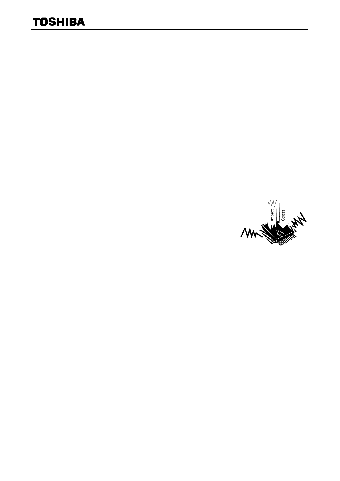
If a device is subjected to especially strong vibration, mechanical shock or stress, the package or the
chip itself may crack. In products such as CCDs whi ch incorporate window glass, thi s could cause
surface flaws in the glass or cause the connection between the glass and the ceramic to separate.
Furthermore, it is known that st ress applied to a semiconductor device through the package
changes the resistance characteristics of the ch ip because of piezoelectri c effects. In analog circuit
design attention must be paid to the problem of package stress as well as to the dangers of vibration
and shock as described above.
Vibration
98
Page 7

3.2 Storage
3.2.1 General Storage
• Avoid storage locations where devices will be exposed to moisture or direct sunlight
• Follow the instructions printed on the device cartons regarding
transportation and storage.
• The storage area temperature should be kept within a
temperature range of 5°C to 35°C, and relative humidity
should be maintained at between 45% and 75%.
• Do not store devices in the presence of harmful (especially
corrosive) gases, or i n dusty conditions.
• Use storage areas where there is minimal temperature
fluctuation. Rapid temperature changes can cause moisture to form on stored devices, resulting
in lead oxidation or corrosion. As a result, the solderability of the leads will be degraded.
• When repacking devices, use anti-static containers.
• Do not allow external forces or loads to be applied to devices while they are in storage.
• If devices have been stored for more than two years, their electrical characteristics should be
tested and their leads should be tested for ease of soldering before they are used.
[6] Handling Guide
Humidity:
Temperature:
99
Page 8

3.3 Design
Care must be exercised in the design of electronic equipment to achieve the desired reliability. It is
important not only to adhere to specifications concerning absolute maximum ratings and
recommended operating conditions, it is also important to consider the overall environment in which
equipment will be used, including factors such as the ambient temperature, transient noise and
voltage and current surges, as well as mounting conditions which affect device reliability. This sectio n
describes some general precautions which you should observe when designing ci rcuits and when
mounting devices on printed circuit boards.
For more detailed information about each product family, refer to the relevant individual technical
datasheets available from Toshiba
3.3.1 Absolute Maximum Ratings
The absolute maximum ratings are rated values which must not be
exceeded during operation, even for an instant. Although absolute
maximum ratings differ from product to product, they essentially
concern the voltage and current at each pin, the allowable power
dissipation, and the junction and storage temperatures.
If the voltage or current on any pin exceeds the absolute maximum
rating, the device’s internal circuitry can become degraded. In the worst case, heat generated in
internal circuitry can fuse wiring or cause the semiconductor chip to break down.
If storage or operating temperatures exceed rated values, the package seal can deteriorate or the
wires can become disconnected due to the differences between the thermal expansion coefficients of
the materials from which the device is constructed.
[6] Handling Guide
Do not use devices under conditions in which their absolute maximum
ratings (e.g. current, voltage, power dissipation or temperature) will be
exceeded. A device may break down or its performance may be degraded,
causing it to catch fire or explode resulting in injury to th e user.
3.3.2 Recommended Operating Conditions
The recommended ope r ating conditions for each device are those necessary to guarantee that the
device will operate as specified in the datasheet.
If greater reliability is required, derate th e device’s absolute maximum ratings for voltage, current,
power and temperature before using it.
3.3.3 Derating
When incorporating a device into your design, reduce its rated absolute maximum vo ltage, current,
power dissipation and operating temperature in order to ensure high reliability.
Since derating differs from application to application, refer to the technical datasheets available for
the various devices use d in your design.
100
Page 9

3.3.4 Input processing
[6] Handling Guide
Inputs to CMOS ICs have such a high impedance that
the logic level becomes undefined under open input
conditions. Should the floating input be neither High nor
Low, both P-channel and N-channel transistors turn on,
and unnecessary supply current flows.
Therefore, as shown in Figure 3.1, be sure to connect
unused input lines to V
, GND or other inputs and the
CC
output to the logic level determined by the inputs.
In the case of CMOS, if a soldered part has poor contact,
a malfunction of the system or an increase in supply
current will occur. Therefore, care must be taken when
soldering.
3.3.5 Inputs to a Printed Circuit Board
When the input pin of a printed circuit board is
connected directly to a CMOS input, that input floats
electrically. This condition is the same as a when a single
IC is being transported or stored. It is advisable, therefore,
to connect this input to V
or GND via a resistance on
CC
the printed circuit board, as shown in Figure 3.2.
3.3.6 Power Source Design
VCC
※
※
GND (※Unused gate)
Figure 3.1 Tre atment of Inputs
R
R
R
∼
R:
100 kΩ
−
VDD
Figure 3.2 Input Processing by
Printed Circuit Board
In general, CMOS has a small cu rrent consumption in comparison with bipolar digital ICs, and
therefore it only needs a low-capacity power su pply. However, in practice CMOS consumes power
during transition, and therefore, it is necessary to keep the high-frequency impedance of the power
source at a low level.
It is advisable to make the wiring of the power source (V
insert, as a high-frequency filter, a capacitor of from 0.001 µF to 0.1 µF between V
) and GND lines thick and short, and
CC
and GND for
CC
each IC.
Also, it is recommended that a capacitor of from 10 µF to 100 µF be inserted between the power
supply input and GND as a low-freq uency filter. The mean supply current varies considerably
depending upon the operating frequency of the system, the existence of capacitive load, the power
supply voltage and the rise and fall of the input signal. When using a simple power supply consisting
of a battery and a zener diode, if the mean supply current is high, please be careful with the power
supply, as its power is low. When there is overshoot or undershoot during the power supply’s
transition time use a filter or similar device so that the absolute maximum rating is not exceeded.
101
Page 10

3.3.7 Effect of Slow Rise and Fall Time on Input
When a waveform with a slow rise and fall time is applied to a CMOS input, the output will
sometimes tend to oscillate around V
because the CMOS gate becomes an equivalent linear amplifier in the vicinity of V
power source ripples and noise components are amplified and appear in the output.
When these power source ripples exceed the absolute maximum rating, it not only effects operation
but may also cause the device to break down. In particular, care must be ta ken while the power is on
if the input signal is slow to rise and fall.
Therefore, as mentioned in section 3.3.6, to stabilize the power supply, a filter capacitor should be
inserted between V
fall times specified in the recommended operating conditions.
and GND. In addition, the design should take into account of the input rise and
CC
(the circuit threshold voltage) of the input waveform. This is
th
3.3.8 Output Short-Circuit
In the C2MOSTM ICs Series, a buffer is added to the output, and both flow-out (IOH) and flow-in
(I
) current drive is possible. For this reason, excessive current will flow in a C2MOSTM output
OL
when the high-level output line is shorted to the GND line or when the low-level output line is
shorted to the VCC line. In particular, when the supply voltage is high, IOH and IOL are excessive
and may damage the device; care m ust be taken not to cause an output short circuit.
It is, of course, impossib le to directly connect ordinary outputs together, but in the case of an IC with
a three-state output, a wired OR connection is permitted, provided that no more than two outputs are
enabled simultaneously.
[6] Handling Guide
, and minute
th
3.3.9 Capacitors Connected to Signal Line or VCC/GND
To reduce signal delay or to eliminate noise, a capacitor of up to
500 pF can be connected directly to the signal line. However, if a
capacitor of over 500 pF is used, it must be connected via a
resistor, as shown in Figure 3.3, and not connected directly .
This resistor limits the flow of the current to the CMOS output
parasitic circuit whe n the power supply is turned on or off. The
resistor also prevents prolonged shorting of the CMOS output.
R
C
R: Output current-limiting resistance
Figure 3.3 How to Insert a
Capacitor
102
Page 11

3.3.10 Wiring Precautions
(1) Output waveform distortion
Since the output impedances of the Mini-MOS Series are very low, distortion is sometimes
caused in the output waveform by the L component of the wiring. This occurs when the wiring
connected to the output pin is long or when capacitance is connected between the signal line and
V
or GND. Therefore, when designing a printed circuit board, take care not to make the signal
CC
wiring too long. On the clock signal line, distortion of the waveform causes malfunctions.
(2) Precautions for wiring arrangements
The outputs from the Mini-MOS Series have fast rise and fall times, and swing between V
and GND; therefore they become a noise source to other signals. It is preferable to locate the
output away from components which are sensitive to noise from an analog circuit. Also, the
number of loads and the wiring length should be minimized.
(3) Termination
Due to their physical and electrical characteristics, the Mini-MOS Series are apt to cause
overshoot and undershoot; this leads to malfunction of the circuit or the breakdown of passive
ICs. These problems can be prevented to some extent by terminating the signal line. Figure 3.4
shows examples of terminati on.
(a) Termination Using RC Components (b) Termination Using Diodes
[6] Handling Guide
CC
Figure 3.4 Examples of Termination
(4) Fan-out
In the case of a mutual interface between CMOS ICs, the input impedance of CMOS is so large
that there is little limitation on the number of fan-outs. However, there is a need to consider the
increase in propagation time due to the effect of adding load capacitance and the increase in
power consumption.
The input capacitance of CMOS is about 5 pF per input. If ten fan-outs are taken, for example,
the load capacitance is 50 pF. Additionally, the line capacitance of the printed circuit board must
be taken into account. This shows that the processing speed of the system is controlled not only
by the circuit components but also by the fan-out.
When designing a syste m using CMOS ICs, carefully consider the fan-out.
103
Page 12

s
3.3.11 Latch-up
CMOS devices are subject to latch-up, an undesirable condition in which a parasitic PNPN junction
(thyristor) in the CMOS IC conducts. An abnormal current of several hundred mA can flow between
VCC and GND, destroying the IC.
Latch-up occurs when the voltage applied to the input or output pins exceeds the prescribed
absolute maximum rating value, causing a large current to flow in the device, or when the V
voltage exceeds (even momentarily) the absolute ma ximum rating value causing internal components
to break down. Latch-u p results in a large, continuous current between VCC and GND and can cause
overheating and burn-out. To avoid this, observe the following precautions.
(1) Ensure that the voltage level on the input/output pins is no higher than V
V
device, please refer to the datasheet for the device in question.)
(2) Do no t subject the device to abnormal noise.
(3) Fix the potential of any unused input pins to V
(4) Do not connect output pins directly to other output pins, or to V
Since ample margin against latch-up is provided, there is no problem if Min-CMOS devices are
used within their specifications. However, since the interface component may receive excessive
surges, it is recommended that protective circuits be added, as shown in Figure 3.5.
[6] Handling Guide
pin
CC
and no lower than
CC
, taking into account the timing at power-on. (As the VCC and VSS levels vary from device to
SS
or VSS.
CC
or VSS.
CC
R
I/O
I/O
Figure 3.5 Example of Latch-up Prevention Methods
3.3.12 Electrical Discharge and Precautions against Noise
The Mini-MOS Series have ample margin for handling noise such as electrical discharge. Figure 3.6
show a circuit for ESD testing and Table 3.1 shows the results of ESD tests for various devices.
Input
or
R
A
Output
V
, GND
CC
R
EIAJ Method : C = 200 pF
R = 0 Ω
MIL-STD Method : C = 100 pF
C = 1.5 kΩ
I/O
Figure 3.6 Test Circuit
104
Page 13

[6] Handling Guide
Table 3.1 Test Result
Name
TC7MH244FK >±200 V >±200 V >±2000 V >±2000 V
TC7MET244AFK >±200 V >±200 V >±2000 V >±2000 V
TC7MZ244FK >±200 V >±200 V >±2000 V >±2000 V
TC7MA244FK >±200 V >±200 V >±2000 V >±2000 V
However, input and output signal lines are long in many cases and have distributed inductance or
reactance.
Therefore, if these lines are directly connected to CMOS, various problems can arise.
Possible problems are malfunction due to induced noise, or destruction of the input/output elements
due to a surge. Reducing the signal line impedance (driving impedance) or inserting noise-eliminatin g
circuits on the receiving side are two ways of dealing with the former problem; surge protection
measures are taken to cope with the latter.
Figure 3.7 shows an example of noise and surge protection.
Alternatively, the PCB can be isolated using a photocoupler or a lead relay connection.
Note that it is not necessary to make design allowances for the overshoot and undershoot which can
occur under light lo ads.
EIAJ Method MIL-STD Method
Input Output Input Output
(a) Noise protection (b) Surge protection
Figure 3.7 Protection Circuits
105
Page 14

k
3.3.13 Meta-Stable Characteristics
When the setup time or hold-time of a flip-flop is not adhered to the device’s output response is
uncertain. This phenomenon is called meta-stability.
[6] Handling Guide
Asynchronous Input
Asynchronous Data
Clock
Output
Clock
ts > min
t
pd
<
max
D Q
CK
t
h
> min
Synchronous Output
t
s??
th??
??
t
pd
The diagram shown above descri bes a meta -stable state which can ge nerate a gl itch or incre ase the
propagation delay time . If the asynchronous signal is an input to a flip-flo p which is clocked by the
internal clock of a synchronous system, the meta-stable state is unavoidable.
Therefore, in order to avoid this problem, it is recommended that the timing requirements specified
in the data sheet be observed. When a synchronous signal is used, care must be taken with the output
signal.
Figure 3.8 shows an example of how to solve this problem. In this case, if the difference in phase
between CK1 and CK2 is the same as the tpd (output clock) of the first stage flip-flop, care must be
taken.
Note: If CK1 and CK2 cannot be used together, the synchronous clock signal used for CK1 should be phase-
shitted and applied as the clock for Second stage flip-flop (CK2) (i.e.
D Q
CK1
Cloc
D Q
CK2
2CK = CK1)
Synchronous Output Asynchronous Input
Figure 3.8 Solving the Meta-stable Problem
106
Page 15

j
j
3.3.14 Thermal Design
The failure rate of sem iconductor devices is greatly increased as operating temperatures increase.
As shown in Figure 3.9, the internal thermal stress on a device is the sum of the ambient temperature
and the temperature rise due to power dissipation in the device. Therefore, to achieve optimum
reliability, observe the following precautions concerning thermal design:
(1) Keep the ambient temperature (Ta) as low as possible.
(2) If the device’s dynamic power dissipati on is relatively large, select the most appropriate circuit
board material, and consider the use of heat sinks or of forced air cooling. Such measures will
help lower the thermal resistance of the package.
(3) Derate the device’s absolute maximum ratings to minimize thermal stress from power dissipation.
θja = θjc + θca
θja = (Tj − Ta)/P
θjc = (Tj − Tc)/P
θca = (Tc − Ta)/P
in which θja = thermal resistance between junction and surrounding air (°C/W)
θjc = thermal resistance between junction and package surface, or internal thermal
resistance (°C/W)
θca = thermal resistance between packa ge surface and surrounding ai r, or external
thermal resistance (°C/W)
Tj = junction temperature or chip temperature (°C)
Tc = package surface temperature or case temperature (°C)
Ta = ambient temperature (°C)
P = power dissipation (W)
3.3.15 Interfacing
[6] Handling Guide
Ta
θca
Tc
c
θ
T
Figure 3.9 Thermal Resistance of Package
When connecting inpu ts and outputs between devices, make sure input voltage (VIL/VIH) and
output voltage (V
connecting devices operating at different supply voltages, such as in a dual-power-supply system, be
aware that erroneous power-on and power-off sequences can result in device breakdown. For details of
how to interface particular devi ces, consult the relevant technical datasheets and databoo ks . If you
have any questions or doubts about interfacing, contact your nearest Toshiba office or distributor.
OL/VOH
) levels are matched. Otherwise, the devices may malfunction. When
107
Page 16

3.3.16 External Noise
Printed circuit boards with long I/O or signal pattern lines are
vulnerable to induced noise or surges from outside sources.
Consequently, malfunctions or breakdowns can result from
overcurrent or overvoltage, depending on the types of device
used. To protect against noise, lower the impedance of the
pattern line or insert a noise-canceling circuit. Protective
measures must also be taken against surges.
For details of the appropriate protective measures for a
particular device, consult the relevant databook.
3.3.17 Electromagnetic Interference
Widespread use of electrical and electronic equipment in recent years has brought with it radio and
TV reception problems due to electromagnetic interference. To use the radio spectrum effectively and
to maintain radio communications quality, each country has formulated regulations limiting the
amount of electromagnetic interference which can be generated by individual products.
Electromagnetic interference includes conduction noise propagated through power supply and
telephone lines, and noise from direct electromagnetic waves radiated by equipment. Different
measurement methods and corrective measures are used to assess and counteract each specific type
of noise.
Difficulties in controlling electromagnetic interference derive from the fact that there is no method
available which allows designers to calculate, at the design stage, the strength of the electromagnetic
waves which will emanate from each component in a piece of equipment. For this reason, it is only
after the prototype equipment has been completed that the designer can take measurements using a
dedicated instrument to determine the strength of electromagnetic interference waves. Yet it is
possible during system design to incorporate some measures for the prevention of electromagnetic
interference, which can facilitate taking corrective measures once the desi gn has been completed.
These include installing shields and noise filters, and increasing the thickness of the power supply
wiring patterns on the printed circuit board. One effective method, for example, is to devise several
shielding options during design, and then select the most suitable shielding method based on the
results of measurements taken after the prototype has been completed.
[6] Handling Guide
Input/Output
Signals
3.3.18 Peripheral Circuits
In most cases semiconductor devices are used with peripheral circuits and components. The input
and output signal volta ges and currents in these circuits must be chosen to match the semiconductor
device’s specifications. The following factors must be taken into account.
(1) Inappropriate voltages or currents applied to a device’s input pins may cause it to operate
erratically. Some devices contain pull-up or pull-down resistors. When designing your system,
remember to take the effect of this on the voltage and current levels into account.
(2) The output pins on a device have a predetermined external circuit drive capability. If this drive
capability is greater than that required, either incorporate a com pe nsating circuit into your
design or carefully sel ect suitable compone nts for use in external circuits.
108
Page 17

3.3.19 Safety Standards
Each country has safety standards which must be observed. These safety standards include
requirements for quality assurance systems and design of device insulation. Such requirements must
be fully taken into account to ensure that your design conforms to the applicable safety standards.
3.3.20 Other Precautions
(1) When designing a system, be sure to incorporate fail-safe and other appropriate measures
according to the intended pu rpose of your system. Also, be sure to debug your system under
actual board-mounted conditions.
(2) If a plastic-package device is placed in a strong electric field, surface leakage may occur due to
the charge-up phenomenon, resulting in device malfunction . In such cases take appropriate
measures to prevent this problem, for example by protecting the package surface with a
conductive shield.
(3) With some microcomputers and MOS memory devices, caution is required when powering o n or
resetting the device. To ensure that your design does not violate device specifications, consult the
relevant databook for each constituent device.
[6] Handling Guide
(4) Ensure that no conductive material or object (such as a metal pin) can drop onto and short the
leads of a device mounted on a printed circuit board.
3.4 Inspection, Testing and Evaluation
3.4.1 Grounding
Ground all measuring instruments, jigs, tools and soldering irons to earth.
Electrical leakage may cause a device to break down or may result in
electric shock.
109
Page 18

3.4.2 Inspection Sequence
(1) Apply voltage to the test jig only a fter inserting the device secure ly into it. When applying or
removing power, observe the relevant precautions, if any.
(2) Make sure that the voltage applied to the devi ce is o ff before rem o ving the de vi ce from the test jig.
Otherwise, the device may undergo performance degradation or be destroyed.
(3) Make sure that no surge voltages from the measuring equipment are applied to the device.
(4) The chips housed in tape carrier packages (TCPs) are bare chips and are therefore exposed.
During inspection take care not to crack the chip or cause any flaws in it.
Electrical contact may also cause a chip to become faulty. Therefore make sure that nothing
comes into electrical contact with the chip.
[6] Handling Guide
1. Do not insert devices in the wrong orientation. Make sure that the
positive and negative electrodes of the power supply are correctly
connected. Otherwise, the rated maximum current or maximum power
dissipation may be exceeded and the device may break down or undergo
performance degradatio n, causing it to catch fire or e xplode, resulting in
injury to the user.
2. When conducting any kind of evaluation, inspection or testing using AC
power with a peak voltage of 42.4 V or DC power exceeding 60 V, be sure
to connect the electrodes or probes of the testing equipment to the device
under test before powering it on. Connecting the electrodes or probes of
testing equipment to a device while it is powered on may result in electric
shock, causing injury.
3.5 Mounting
There are essentially two main types of semicondu ctor device package: lead inse rtion and surface
mount. During mounting on printed circuit boards, devices can become contaminated by flux or
damaged by thermal stress from the soldering process. With surface-mount devices in particular, the
most significant problem is thermal stress from solder reflow, when the entire package is subjected to
heat. This section descri bes a recommended temperature profile for each mounting method, as well as
general precautions which you should take when mo unting devices on printed circuit boards. Note,
however, that even for devices with the same package type, the appropriate mounting method varies
according to the size of the chip and the size and shape of the lead frame. Therefore, please consult
the relevant technical datasheet and databook.
3.5.1 Lead Forming
Semiconductor devices must undergo a process in which the leads are cut and formed before the
devices can be mounted on a printed circuit board. If undue stress is applied to the interior of a device
during this process, mechanical breakdown or performance degradation can result. This is
attributable primarily to differences between the stress on the device’s external leads and the stress
1. Always wear protective glasses when cutting the leads of a device with
clippers or a similar tool. If you do not, small bits of metal fl ying off the
cut ends may damage your eyes.
2. Do not touch the tips of device leads. Because some types of device have
leads with pointed tips, you may prick your finger.
110
Page 19

[6] Handling Guide
on the internal leads. If the relative difference is great enough, the device’s internal leads, adhesive
properties or sealant can be damaged. Observe these precautions during the lead-forming process
(this does not apply to surface-mount devices):
(1) Lead insertion hole intervals on the printed circuit board should match the lead pitch of the
device precisely.
(2) If lead insertion hole intervals on the printed circuit board do not precisel y match the lead pitch
of the device, do not attem p t to forcibly insert devices by pressi ng on them or by pulling on their
leads.
(3) For the minimum clearance specification between a device and a
printed circuit board, refer to the relevant device’s datasheet and
databook. If necessary, achieve the required clearance by forming the
device’s leads appropriately. Do not use the spacers which are used to
raise devices above the su rface of the printed circuit board during
soldering to achieve clearance. These spacers normally continue to
expand due to heat, even after the solder has begun to solidify; this applies severe stress to the
device.
(4) Observe the following precautions when forming the leads of a device prior to mounting.
• Use a tool or jig to secure the lead at its base (where the lead meets the device package)
while bending so as to avoid mechanical stress to the device. Also avoid bending or
stretching device leads repeatedly.
• Be careful not to damage the lead during lead forming.
• Follow any other precautions described in the individual datasheets and databooks for each
device and package type.
3.5.2 Socket Mounting
(1) Wh en socket mounting devices on a printed circuit board, use sockets which match the inserted
device’s package.
(2) Use sockets whose contacts have the appropriate contact pressure. If the contact pressure is
insufficient, the socket may not make a perfect contact when the device is repeatedly inserted and
removed; if the pressure is excessively high, the device leads may be bent or damaged when they
are inserted into or removed from the socket.
(3) When soldering sockets to the printed circuit board, use sockets whose construction prevents flux
from penetrating into the contacts or which allows flux to be completely cleaned off.
(4) Make sure the coatin g agent applied to the printed circuit board for moisture-proofing purposes
does not stick to the socket contacts.
(5) If the device leads are severely bent by a socket as it is inserted or removed and you wish to
repair the leads so as to continue using the device, make sure that this lead correction is only
performed once. Do not use devices whose leads have been corrected more than once.
(6) If the printed circuit board with the devices mounted on it will be subjected to vibration from
external sources, use sockets which have a strong contact pressure so as to prevent the sockets
and devices from vibratin g relative to one another.
111
Page 20

3.5.3 Soldering Temperature Profile
The soldering temperature and heating time vary from device to device. Therefore, when specifying
the mounting conditions, refer to the individual datasheets and databooks fo r the devices used.
(1) Using a soldering iron
Complete soldering within ten seconds for lead temperatures of up to 260°C, or within three
seconds for lead temperatures of up to 350°C.
(2) Using medium infrared ray reflow
• Heating top and bottom with long or medium infrared rays is recommended(see Figure3.10).
Product flow
Long infrared ray heater (preheating)
[6] Handling Guide
Medium infrared ray heater
(reflow)
Figure 3.10 Heating Top and Bottom with Long or Medium Infrared Rays
• Complete the infrared ray reflow process within 30 seconds at a package surface
temperature of between 210°C and 240°C.
• Refer to Figure 3.11 for an example of a good temperature profile for infrared or hot air
reflow.
(°C)
240
210
160
140
Package surface temperature
60-120
seconds
30
seconds
or less
Time (in seconds)
Figure 3.11 Sample Tempera ture Profile for Infrared or Hot Air Reflow
(3) Using hot air reflow
• Complete hot air reflow within 30 seconds at a package surface temperature of between
210°C and 240°C
• For an example of a recommended temperature profile, refer to Figure 3.11 above.
112
Page 21

3.5.4 Flux Cleaning and Ultrasonic Cleaning
(1) Wh en cleaning circuit boards to remove flux, make sure that no residual reactive ions such as Na
or Cl remain. Note that organic solvents react with water to generate hydrogen chloride an d
other corrosive gases which can degrade device performance.
(2) Washing devices with water will not cause any problems. However, make sure that no reactive
ions such as sodium and chlorine are left as a residue. Also, be sure to dry devices sufficiently
after washing.
(3) Do n ot rub device markings with a bru sh or with your hand during cleanin g or while the devices
are still wet from the cleaning agent. Doing so can rub off the markings.
(4) The dip cleaning, shower cleaning and steam cleaning processes all involve the chemical action of
a solvent. Use only recommended solvents for these cleaning methods. When immersing devices
in a solvent or steam bath, make sure that the temperature of the liquid is 50°C or below, and
that the circuit board is removed from the bath within one minute.
(5) Ultra sonic cleaning should not be used with hermetically-se aled ceramic packages such as a
leadless chip carrie r (LCC), pin grid array (PGA) or charge-coupled device (CCD), because the
bonding wires can become disconnected due to resonance during the cleaning process. Even if a
device package allows ultrasonic cleaning, limit the duration of ultrasonic cleaning to as short a
time as possible, since long hours of ultrasonic cleaning degrade the adhesion between the mold
resin and the frame material. The following ultrasonic cleaning conditions are recommended:
Frequency: 27 kHz ∼ 29 kHz
Ultrasonic output power: 300 W or less (0.25 W/cm
Cleaning time: 30 seconds or less
Suspend the circuit board in the solvent bath during ultrasonic cleaning in such a way that the
ultrasonic vibrator does not come into direct contact with the circuit board or the device.
2
or less)
[6] Handling Guide
113
Page 22

3.5.5 No Cleaning
If analog devices or high-speed devices are used without being cleaned, flux residues ma y cause
minute amounts of leakage between pins. Similarly, dew condensation, which occurs in environments
containing residua l chlorine when power to the device is on, may cause between-lead leakage or
migration. Therefore, Toshiba recommends that these devices be cleaned.
However, if the flux used contains only a small amount of halogen (0.05 W% or less), the devices may
be used without cleaning without any problems.
3.5.6 Circuit Board Coating
When devices are to be used in equipment requiring a high degree of reliability or in extreme
environments (where moisture, corrosive gas or dust i s present), circuit boards may be coa ted for
protection. However, before doing so, you must ca refully consider the possi bl e stress and
contamination effects that may result and then choose the coating resin which results in the
minimum level of stress to the device.
[6] Handling Guide
114
Page 23

3.6 Protecting Devices in the Field
3.6.1 Temperature
Semiconductor devi ces are generally more sensitive to temperature than are other electronic
components. The various electrical characteristics of a semiconductor device are dependent on the
ambient temperature at which the device is used. It is therefore necessary to understand the
temperature characteri stics of a device and to incorpo rate device derating into circuit des ign. Note
also that if a device is used above its maximum temperature rating, device deterioration is more rapid
and it will reach the end of its usable life sooner than expected.
3.6.2 Humidity
Resin-molded devices are sometimes improperly sealed. When these devices are used for an
extended period of time in a high-humidity environment, moisture can penetrate into the device and
cause chip degradation or malfunction. Furthermore, when devices are mounted on a regular printed
circuit board, the impedance between wiring components can decrease under high-humidity
conditions. In systems which require a high signal-source impedance, circuit board leakage or leakage
between device lead pins can cause malfunctions. The application of a moisture-proof treatment to the
device surface should be considered in this case. On the other hand, operation under low-humidity
conditions can damage a device due to the occurrence of electro static discharge. Unless dam p -proofing
measures have been specifically taken, use devices only in environments with appropriate ambient
moisture levels (i.e. within a relative humidity range of 40% to 60%).
[6] Handling Guide
3.6.3 Corrosive Gases
Corrosive gases can cause chemical reactions in devices, degrading device characteristics.
For example, sulphur-bearing corrosive gases emanating from rubber placed near a device
(accompanied by condensation under high-humidity conditions) can corrode a de vice’s leads. The
resulting chemical reaction between leads forms foreign particles which can cause electrical leakage.
3.6.4 Radioactive and Cosmic Rays
Most industrial and consumer semiconductor devices are not designed with protection against
radioactive and cosmic rays. Devices used in aerosp ace equipment or in radioacti ve environments
must therefore be shielded.
3.6.5 Strong Electrical and Magnetic Fields
Devices exposed to strong magnetic fields can undergo a polarization phenomenon in their plastic
material, or within the chip, which gives rise to ab no rmal symptoms such as impedance changes or
increased leakage current. Failures have been reported in LSIs mounted near malfunctioning
deflection yokes in TV sets. In such cases the device’s installation location must be changed or the
device must be shielded against the electrical or magnetic field. Shielding against magnetism is
especially necessary for devices used in an alternating magnetic field because of the electromotive
forces generated in this type of environment.
115
Page 24

[6] Handling Guide
3.6.6 Interference from Light (ultraviolet rays, sunlight, fluorescent lamps and incandescent
lamps)
Light striking a semiconductor device generates electromotive force due to photoelectric effects. In
some cases the device can malfunction. This is especially true for devices in which the internal chip is
exposed. When designing circuits, make sure that devices are protected against incident light from
external sources. This problem is not limited to optical semiconductors and EPROMs. All types of
device can be affected by li ght.
3.6.7 Dust and Oil
Just like corrosive gases, dust and oil can cause chemical reactions in devices, which will ad versely
affect a device’s electrical characteristics. To avoid this problem, do not use devices in dusty or oily
environments. This is especially important for optical devices because dust and oil can affect a
device’s optical characteristics as well as its physical integrity and the electrical performance factors
mentioned above.
3.6.8 Fire
Semiconductor devices are combustible; they can emit smoke and catch fire if heated sufficiently.
When this happens, some devi ces may generate poisonous gases. Devices should therefore never be
used in close proximity to an open flame or a heat-generating body, or near flammable or combustible
materials.
3.7 Disposal of Devices and Packing Materials
When discarding unused devices and packing materials, follow all procedures specified by local
regulations in order to protect the environment against contamination.
116
 Loading...