

Toshiba SD-H400-S-TU, SD-H400 Installation Manual
1
4
5
6
3
2
',*,7$/0(',$6(59(5
6'+
,QVWDOODWLRQ*XLGH
70971991 2003 Toshiba Corporation
DIGITAL VIDEO
SD-H400 Covers.fm Page i Monday, June 9, 2003 3:08 PM
i
Table of Contents
Safety Precautions. . . . . . . . . . . . . . . . . . . . . . . . . . . . . . . . . . . . . . . . . . . . . . . . . . . . . . . . . . . . . . . . . . . . . . . . . . . . iii
Safety Instructions . . . . . . . . . . . . . . . . . . . . . . . . . . . . . . . . . . . . . . . . . . . . . . . . . . . . . . . . . . . . . . . . . . . . . . . . . . . iv
Power Source . . . . . . . . . . . . . . . . . . . . . . . . . . . . . . . . . . . . . . . . . . . . . . . . . . . . . . . . . . . . . . . . . . . . . . . . . . . . . . . vi
FCC Information. . . . . . . . . . . . . . . . . . . . . . . . . . . . . . . . . . . . . . . . . . . . . . . . . . . . . . . . . . . . . . . . . . . . . . . . . . . . . vi
Precautions . . . . . . . . . . . . . . . . . . . . . . . . . . . . . . . . . . . . . . . . . . . . . . . . . . . . . . . . . . . . . . . . . . . . . . . . . . . . . . . . viii
Notes on Disc . . . . . . . . . . . . . . . . . . . . . . . . . . . . . . . . . . . . . . . . . . . . . . . . . . . . . . . . . . . . . . . . . . . . . . . . . . . . . . . ix
Chapter 1: Identification of Controls . . . . . . . . . . . . . . . . . . . . . . . . . . . . . . . . . . . . . . . . . . . . . . . . . . . . . . . . 1
Front Panel . . . . . . . . . . . . . . . . . . . . . . . . . . . . . . . . . . . . . . . . . . . . . . . . . . . . . . . . . . . . . . . . . . . . . . . . . . . . . . . . . . 2
Rear Panel . . . . . . . . . . . . . . . . . . . . . . . . . . . . . . . . . . . . . . . . . . . . . . . . . . . . . . . . . . . . . . . . . . . . . . . . . . . . . . . . . . 3
DVD Display . . . . . . . . . . . . . . . . . . . . . . . . . . . . . . . . . . . . . . . . . . . . . . . . . . . . . . . . . . . . . . . . . . . . . . . . . . . . . . . . 4
Remote Control . . . . . . . . . . . . . . . . . . . . . . . . . . . . . . . . . . . . . . . . . . . . . . . . . . . . . . . . . . . . . . . . . . . . . . . . . . . . . . 5
Chapter 2: Getting Started . . . . . . . . . . . . . . . . . . . . . . . . . . . . . . . . . . . . . . . . . . . . . . . . . . . . . . . . . . . . . . . . 9
Using This Guide . . . . . . . . . . . . . . . . . . . . . . . . . . . . . . . . . . . . . . . . . . . . . . . . . . . . . . . . . . . . . . . . . . . . . . . . . . . . 10
Cables and Accessories . . . . . . . . . . . . . . . . . . . . . . . . . . . . . . . . . . . . . . . . . . . . . . . . . . . . . . . . . . . . . . . . . . . . . . . 11
Connecting the Phone Line . . . . . . . . . . . . . . . . . . . . . . . . . . . . . . . . . . . . . . . . . . . . . . . . . . . . . . . . . . . . . . . . . . . . 12
Using Your SD-H400 with a Cable or Satellite Box . . . . . . . . . . . . . . . . . . . . . . . . . . . . . . . . . . . . . . . . . . . . . . . . . 13
Chapter 3: Setup Connections . . . . . . . . . . . . . . . . . . . . . . . . . . . . . . . . . . . . . . . . . . . . . . . . . . . . . . . . . . . . 17
Setup 1: Connecting to a TV and Optional VCR . . . . . . . . . . . . . . . . . . . . . . . . . . . . . . . . . . . . . . . . . . . . . . . . . . . . 18
Setup 2: Connecting to Cable or Satellite Box . . . . . . . . . . . . . . . . . . . . . . . . . . . . . . . . . . . . . . . . . . . . . . . . . . . . . 21
Setup 3: Connecting to A/V Receiver, Game Console and VCR . . . . . . . . . . . . . . . . . . . . . . . . . . . . . . . . . . . . . . . 23
Setup 4: Connecting to Optional Audio Equipment . . . . . . . . . . . . . . . . . . . . . . . . . . . . . . . . . . . . . . . . . . . . . . . . . 25
SD-H400 TOC.fm Page i Monday, June 9, 2003 1:47 PM
ii
Chapter 4: Setting Up the Remote Control . . . . . . . . . . . . . . . . . . . . . . . . . . . . . . . . . . . . . . . . . . . . . . . . . . 29
Introduction . . . . . . . . . . . . . . . . . . . . . . . . . . . . . . . . . . . . . . . . . . . . . . . . . . . . . . . . . . . . . . . . . . . . . . . . . . . . . . . . 30
Instructions: TV Power, Volume, and TV Input . . . . . . . . . . . . . . . . . . . . . . . . . . . . . . . . . . . . . . . . . . . . . . . . . . . . 31
Resetting the Programmable Buttons . . . . . . . . . . . . . . . . . . . . . . . . . . . . . . . . . . . . . . . . . . . . . . . . . . . . . . . . . . . . . 33
Setup Codes for Television. . . . . . . . . . . . . . . . . . . . . . . . . . . . . . . . . . . . . . . . . . . . . . . . . . . . . . . . . . . . . . . . . . . . . 34
Setup Codes for Amplifiers. . . . . . . . . . . . . . . . . . . . . . . . . . . . . . . . . . . . . . . . . . . . . . . . . . . . . . . . . . . . . . . . . . . . . 40
Setup Codes for Receivers . . . . . . . . . . . . . . . . . . . . . . . . . . . . . . . . . . . . . . . . . . . . . . . . . . . . . . . . . . . . . . . . . . . . . 42
Chapter 5: Troubleshooting . . . . . . . . . . . . . . . . . . . . . . . . . . . . . . . . . . . . . . . . . . . . . . . . . . . . . . . . . . . . . . 47
Customer Support . . . . . . . . . . . . . . . . . . . . . . . . . . . . . . . . . . . . . . . . . . . . . . . . . . . . . . . . . . . . . . . . . . . . . . . . . . . 48
Troubleshooting . . . . . . . . . . . . . . . . . . . . . . . . . . . . . . . . . . . . . . . . . . . . . . . . . . . . . . . . . . . . . . . . . . . . . . . . . . . . . 49
Chapter 6: Warranty and Specifications . . . . . . . . . . . . . . . . . . . . . . . . . . . . . . . . . . . . . . . . . . . . . . . . . . . 55
Limited Warranty . . . . . . . . . . . . . . . . . . . . . . . . . . . . . . . . . . . . . . . . . . . . . . . . . . . . . . . . . . . . . . . . . . . . . . . . . . . . 56
Specifications . . . . . . . . . . . . . . . . . . . . . . . . . . . . . . . . . . . . . . . . . . . . . . . . . . . . . . . . . . . . . . . . . . . . . . . . . . . . . . . 59
Index . . . . . . . . . . . . . . . . . . . . . . . . . . . . . . . . . . . . . . . . . . . . . . . . . . . . . . . . . . . . . . . . . . . . . . . . . . . . . . 61
SD-H400 TOC.fm Page ii Monday, June 9, 2 003 1:47 PM
iii
Safety Precautions
Safety Precautions
The lightning flash with arrowhead symbol, within an equilateral triangle, is intended to
alert the user to the presence of uninsulated “dangerous voltage” within the product’s
enclosure that may be of sufficient magnitude to constitute a risk of electric shock to
persons.
The exclamation point within an equilateral triangle is intended to alert the user to the
presence of important operating and maintenance (servicing) instructions in the literature
accompanying the appliance.
The symbol for CLASS II (Double Insulation)
WARNING: TO REDUCE THE RISK OF FIRE OR ELECTRIC SHOCK, DO NOT EXPOSE THIS APPLIANCE TO RAIN OR
MOISTURE. DANGEROUS HIGH VOLTAGES ARE PRESENT INSIDE THE ENCLOSURE. DO NOT OPEN THE
CABINET. REFER SERVICING TO QUALIFIED PERSONNEL ONLY.
CAUTION: TO PREVENT ELECTRIC SHOCK, MATCH WIDE BLADE OF PLUG TO WIDE SLOT, FULLY INSERT.
ATTENTION:POUR EVITER LES CHOCS ELECTRIQUES, INTRODUIRE LA LAME LA PLUS LARGE DE LA FICHE DANS LA
BORNE CORRESPONDANTE DE LA PRISE ET POUSSER JUSQU’AU FOND.
CAUTION: This Digital Media Server employs a Laser System.
To ensure proper use of this product, please read this guide carefully and retain for future reference. Should the unit require
maintenance, contact an authorized service location - see service procedure.
Use of controls or adjustments or performance of procedures other than those specified herein may result in hazardous radiation
exposure. To prevent direct exposure to laser beam, do not try to open the enclosure.
Visible and invisible laser radiation when open and interlocks defeated. DO NOT STARE INTO BEAM.
WARNING: Changes or modifications made to this equipment, not expressly approved by Toshiba, or parties authorized by Toshiba , could void the
user’s authority to operate the equipment.
In the spaces provided below, record the Model and Serial No. located on the rear panel of your Digital Media Server.
Model No. _______________________ Serial No. _______________________
WARNING
RISK OF ELECTRIC SHOCK
DO NOT OPEN
AVIS
RISQUE DE CHOC ELECTRIQUE NE
PAS OUVRIR
Introduction-New.fm Page iii Monday, June 9, 2003 4:48 PM

iv
Important Safety Instructions
Important Safety Instructions
This product was designed and manufactured to meet strict quality and safety standards. There are, however, some installation and operation
precautions of which you should be particularly aware. Please read these instructions before operating the equipment and save them for future
reference.
1. Read Instructions—All the safety and operating instructions should be read and understood before the appliance is operated.
2. Retain Instructions—The safety and operating instructions should be retained for future reference.
3. Heed Warnings—All warnings on the appliance and in the operating instructions should be followed.
4. Follow Instructions—All operating and use instructions should be followed.
5. Water and Moisture—The appliance should not be used nea r water - for example, near a bathtub, washbowl, kitchen sink, laundry tub, in a wet
basement or near a swimming pool, etc.
6. An appliance and cart combination should be moved with care. Quick stops, excessive force, and uneven surfaces may cause the appliance and cart
combination to overturn.
7. Tilt/Stability—All televisions must comply with recommended international global safety standards for tilt and stability properties of their cabinet
design. Do not compromise these design standards by applying excessive pull force to the front, or top, of the cabinet, which could ultimately overturn
the product. Also, do not endanger yourself, or children, by placing electronic equipment/toys on top of the cabinet. Such items could unexpectedly fall
from the top of the set and cause product damage and/or personal injury.
8. Ventilation—The appliance should be situated so that its location or position does not interfere with its proper ventilation. For example, the
appliance should not be situated on a bed, sofa, rug, or similar surface that may block the ventilation openings; or, placed in a built-in installation, such
as a bookcase or cabinet that may impede the flow of air through the ventilation openings.
9. Heat—The appliance should be situated away from heat sources such as radiators, heat registers, stoves, or other appliances (including amplifiers)
that produce heat.
10. Power Cord Protection—Power supply cords should be routed so that they are not likely to be walked on or pinched by items placed upon or
against them, paying particular attention to cords and plugs, convenience receptacles, and the point where they exit from the appliance.
11. Object and Liquid Entry—Never push objects of any kind into this product through cabinet slots, as they may touch dangerous voltage points or
short the parts, resulting in the risk of fire or electric shock. Never spill liquid of any kind on this product.
Introduction-New.fm Page iv Monday, June 9, 2003 4:48 PM

v
Important Safety Instructions
12. Lightning—For added protection for this product during storm, or when it is left unattended and unused for long periods of time, unplug it from the
wall outlet and disconect the antenna or cable systems. This will prevent damage to the product due to lightning and power-line surges.
13. Attachments—Do not use attachments not recommended by the product manufacturer as they may cause hazards.
14. Damage Requiring Service—The appliance should be serviced by qualified service personnel when:
A.
THE POWER SUPPLY CORD OR PLUG IS DAMAGED OR FRA YED;
B.
LIQUID HAS SPILLED INTO THE PRODUCT;
C.
THE PRODUCT HAS BEEN EXPOSED TO RAIN OR WATER;
D.
THE PRODUCT DOES NOT OPERATE NORMALLY WHEN YOU FOLLOW THE OPERATING INSTRUCTIONS (ADJUST ONLY THOSE CONTROLS THAT ARE
DISCUSSED IN THE INSTALLATION GUIDE, AS IMPROPER ADJUSTMENT OF OTHER CONTROLS MAY RESULT IN DAMAGE, OFTEN REQUIRIN G
EXTENSIVE WORK BY A QUALIFIED TECHNICIAN TO RESTORE THE PRODUCT TO NORMAL PERFORMANCE);
E.
THE PRODUCT HAS BEEN DROPPED OR THE CABINET DAMAGED;
F.
THE PRODUCT EXHIBITS A DISTINCT CHANGE IN PERFORMANCE.
15. Servicing—The user should not attempt service to the appliance beyond that described in the Troubleshooting section of this guide. All other
servicing should be referred to qualified service personnel.
16. Cleaning—Unplug this product from the wall outlet before cleaning. Do not use liquid cleaners or aerosol cleaners; use a damp cloth for cleaning.
If the product comes in contact with any liquid, unplug the phone line and the power adapter and let the unit dry thoroughly before plugging it back in.
17. Power Source—This product should be operated only from the type of power source indicated on the marking label or in the Installation Guide. If
you are not sure of the type of power supply to your home, consult your dealer or local power company.
18. Overloaded Power Outlets—do not overload wall outlets and extension cords, as this can result in the risk of fire or electric shock.
19. Electric Shock—To reduce the risk of electric shock, do not disassemble this product. Take it to a qualified serviceperson when service or repair
work is required. Opening or removing covers may expose you to dangerous voltage or other risks. Incorrect reassembly can cause electric shock when
this product is subsequently used.
20. Telephone Usage—When using your telephone equipment, basic safety precautions should be always followed to reduce the risk of fire, electric
shock and injury to persons. To reduce the risk of fire, use only No. 26 AWG or larger telecommunic ation line cord.
21. Avoid moving the unit while it is plugged in to avoid accumulative shock and vibration damage to the internal hard disk drive.
22. Keep your fingers well clear of the disc tray as it is closing. Neglecting to do so may cause serious personal injury.
23. Do not use a cracked, deformed, or repaired disc. These discs are easily broken and may cause serious personal injury and apparatus malfunction.
Introduction-New.fm Page v Monday, June 9, 2003 4:48 PM
vi
Power Source
Power Source
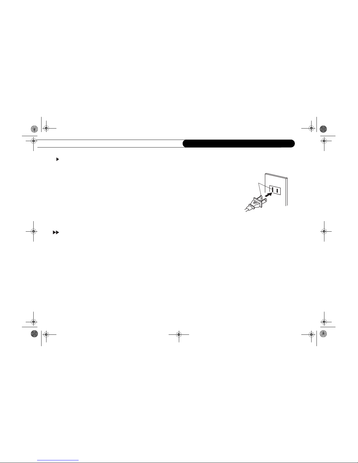
TO USE AC POWER SOURCE
Use the AC polarized line cord provided for operation on AC. Insert the AC cord plug into a standard 120V
60Hz polarized AC outlet.
NOTES:
• Never connect the AC line cord plug to other than the specified voltage (120V 60 Hz). Use the attached
power cord only.
• If the polarized AC cord does not fit into a non-polarized AC outlet, do not attempt to file or cut the blade.
It is the user’s responsibility to have an electrician replace the obsolete outlet.
• If you cause a static discharge when touching the unit from the AC outlet and plug it back in. The unit
should return to normal operation.
FCC Information
Federal Communication Commission (FCC) - This equipment complies with both Part 15 and Part 68 of the FCC rules.
This equipment has been tested and found to comply with the lim its for a Class B digital device, persuant to part 15 of the FCC Rule. These limits are
designed to provide reasonable protection against harmful interference in a residential installation.
This equipment generates, uses, and can radiate radio frequency energy and, if not installed and used in accordance with the instructions, may cause
harmful interference to radio communications.
However, there is no guarantee that interference will not occur in a particular installation. If this equipment does cause harmful interference to radio or
television reception, which can be determined by turning the equipment off and on, the user is encouraged to try to correct the interference by one or
more of the following measures:
- Reorient or relocate the receiving antenna.
- Increase the separation between the equipment and receiver.
- Connect the equipment into an outlet on a circuit different from that to which the receiver is connected.
- Consult the dealer or an experienced radio/TV technician for help.
Wider Hole
and Blade
AC Outlet
Polarized AC Cord Plug
(One blade is wider than the other.)
Introduction-New.fm Page vi Monday, June 9, 2003 4:48 PM
vii
FCC Information
This equipment complies with Part 68 of the FCC Rules and the requirements adopted by ACTA. On the back of this equipment is a label that contains
a product identifier in the format US:AAAEQ##TXXXX. If requested, this information must be provided to your telephone company.
A plug and jack used to connect this equipment to the premises wiring and telephone network must comply with the applicable FCC Part 68 rules and
requirements adopted by ACTA. A compliant telephone cord and modular plug is provided with this product. It is designed to be connected to a
compatible modular jack that is also compliant. See installation instructions for details.
The REN is used to determine the number of devices that may connect to a telephone line. Excessive RENs on a telephone line may result in the devices
not ringing in response to an incoming call. In most but not all areas, the sum of the RENs should not exceed five (5.0). To be certain of the number of
devices that may be connected to a line, as determined by the total RENs, contact your local telephone company. For product approved after July 23,
2001, the REN for this product is part of the product identifier that has the format US:AAAEQ##TXXXX. The digits represented by ## are the REN
without the decimal point (e.q., 03 is a REN of 0.3). For earlier products, the REN is separately shown on the label.
If your DIGITAL MEDIA SERVER causes harm to the telephone network, the telephone company will notify you in advance that temporary
discontinuance of service may be required. But if advance notice isn’t practical, the telephone company will notify the customer as soon as possible.
Also, you will be advised of your right to file a complaint with the FCC if you believe it is necessary.
The telephone company may make changes in its facilities, equipment, operations or procedures that could affect the proper functioning of your
equipment. If they do, you will be notified in advance in order for you to make necessary modifications to maintain uninterrupted service.
If trouble is experienced with this unit, for repair or warranty information, please contact customer service at the address and phone listed below. If the
equipment is causing harm to the network, the telephone company may request that you disconnect the equipment until the problem is resolved.
DO NOT DISASSEMBLE THIS EQUIPMENT. It does not contain any user serviceable components.
We recommend the installation of an AC surge arrester in the AC outlet to which this equipment is connected. Telephone companies report that
electrical surges, typically lighting transients, are very destructive to customer terminal equipment connected to AC power sources.
Introduction-New.fm Page vii Monday, June 9, 2003 4:48 PM
viii
Precautions
Precautions
NOTES ON LOCATING
• Place the SD-H400 on a level surface. Do not use it on a shaky or
unstable surface such as a wobbling table or inclined stand. The
loaded disc may come off the proper position and cause damage to
the SD-H400.
• When you place this SD-H400 near a TV, radio, or VCR, the
playback picture may become poor and the sound may be distorted.
In this case, place the SD-H400 away from the TV, radio, or VCR.
TO OBTAIN A CLEAR PICTURE
The SD-H400 is a high technology, precision device. If the optical pickup lens and disc drive parts are dirty or worn down, the picture quality
deteriorates. To obtain a clear picture, we recommend regular inspection
and maintenance (cleaning or parts replacement) every 1,000 hours of
use depending on the operating environment. For details, contact your
nearest dealer.
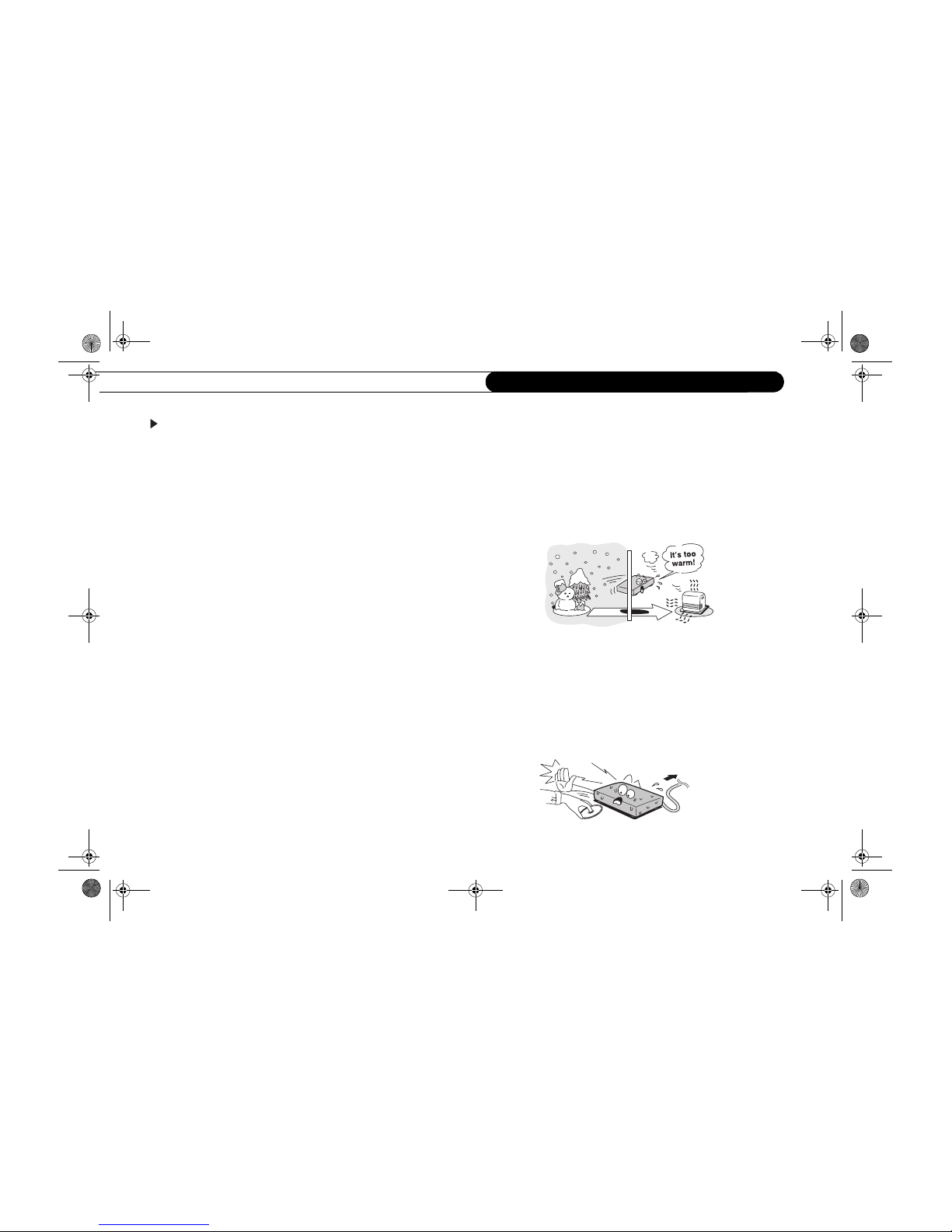
NOTES ON MOISTURE CONDENSATION
Moisture condensation damages the SD-H400. Please read the
following carefully.
Moisture condensation occurs, for example, when you pour a cold drink
into a glass on a warm day. Drops of water form on the outside of the
glass. In the same way, moisture may condense on the optical pick-up
lens inside this unit, one of the most crucial internal parts of the SDH400.
Moisture condensation occurs during the following cases.
• When you bring the SD-H400 directly from a cold place to a warm
place.
• When you use the SD-H400 in a room where you just turned on the
heater, or a place where the cold wind from the air conditioner
directly hits the unit.
• In summer, when you use the SD-H400 in a hot and humid place just
after you move the unit from an air conditioned room.
• When you use the SD-H400 in a humid place.
Do not use the SD-H400 when moisture condensation may occur.
If you use the SD-H400 in such a situation, it may damage discs and
internal parts. Remove the disc, connect the power cord of the SDH400 player to the wall outlet, turn on the SD-H400, and leave it for
two or three hours. After two or three hours, the SD-H400 will have
warmed up and evaporated any moisture. Keep the SD-H400
connected to the wall outlet and moisture condensation will seldom
occur.
Wait!
Wall outle
t
Introduction-New.fm Page viii Monday, June 9, 2003 4:48 PM
ix
Notes On Discs
Notes On Discs
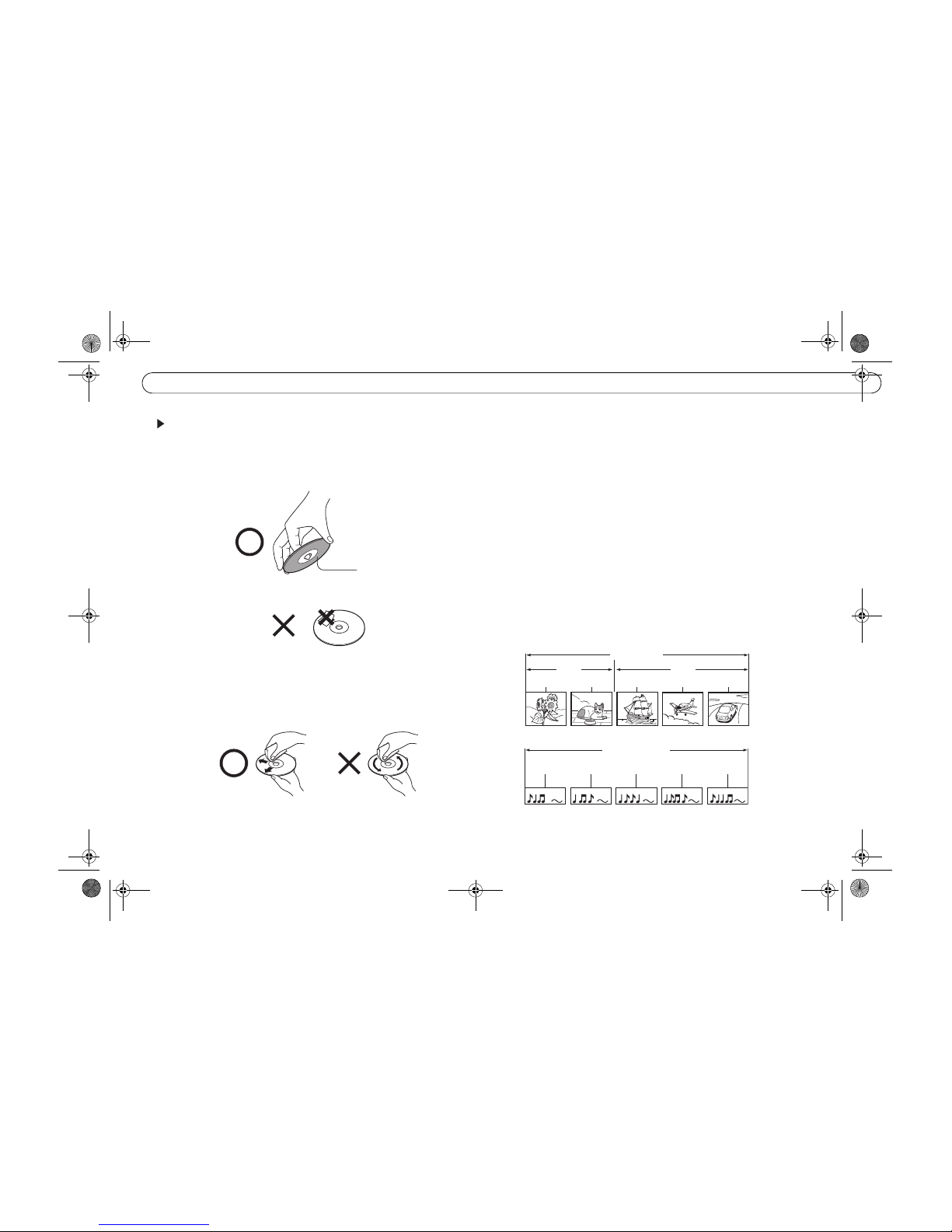
ON HANDLING DISCS
• Do not touch the playback side of the disc.
• Do not attach paper or tape to discs.
ON CLEANING DISCS
• Fingerprints and dust on the disc cause picture and sound
deterioration. Wipe the disc from the center outwards with a soft
cloth. Always keep the disc clean.
• If you cannot wipe off the dust with a soft cloth, wipe the disc lightly
with a slightly moistened soft cloth and finish with a dry cloth.
• Do not use any type of solvent such as thinner, benzine,
commercially available cleaners or antistatic spray for vinyl LPs. It
may damage the disc.
ON STORING DISCS
• Do not store discs in a place subject to direct sunlight or near heat
sources.
• Do not store discs in places subject to moisture and dust such as a
bathroom or near a humidifier.
• Store discs vertically in a case. Stacking or placing objects on discs
outside of their case may cause warping.
STRUCTURE OF DISC CONTENTS
Normally, DVD video discs are divided into titles, and the titles are subdivided into chapters. VIDEO CDs/audio CDs are divided into tracks.
Playback side
Chapter 1
Chapter 2
Chapter 1
Chapter 2
Chapter 3
DVD video disc
Title 1
Title 2
VIDEO CD/Audio CD
Track 1 Track 2 Track 3 Track 4 Track 5
Introduction-New.fm Page ix Monday, June 9, 2003 4:48 PM
x
Notes On Discs
Each title, chapter or track is assigned a number, which is called "title
number", "chapter number" or "track number" respectively.
There may be discs that do not have these numbers.
NOTES ON COPYRIGHT
It is forbidden by law to copy, broadcast, show, broadcast on cable, play
in public, and rent copyrighted material without permission.
DVD video discs are copy protected, and any recordings made from
these discs will be distorted.
This product incorporates copyright protection technology that is
protected by method claims of certain U.S. patents and other intellectual
property rights owned by Macrovision Corporation and other rights
owners. Use of this copyright protection technology must be authorized
by Macrovision Corporation, and is intended for home and other limited
viewing uses only unless otherwise authorized by Macrovision
Corporation. Reverse engineering or disassembly is prohibited.
This product also incorporates copyright protection technology related to
A/V media, that is designed to prevent copying and hence upon the
detection of such signal, recording may be prohibited. This applies to
timer recording too.
ABOUT DVD OPERATION MANUAL
This owner’s manual explains the basic instructions of this SD-H400.
Some DVD video discs are produced in a manner that allows specific or
limited operation during playback. As such, the SD-H400 may not
respond to all operating commands. This is not a defect in the SD-H400.
Refer to instruction notes of discs.
" " may appear on the TV screen during operation.
A " " means that the operation is not permitted by the SD-H400 or
the disc.
NOTES ON REGION NUMBERS
The region number of this SD-H400 is 1. If region numbers, which stand
for their playable area, are printed on your SD-H400 disc and you do not
find or , disc playback will not be allowed by the player. (In
this case, the SD-H400 will display a message on-screen.)
1
ALL
Introduction-New.fm Page x Monday, June 9, 2003 4:48 PM
xi
Notes On Discs
ON VIDEO CDS
This SD-H400 supports VIDEO CDs equipped with the PBC (Version
2.0) function. (PBC is the abbreviation of Playback Control.) You can
enjoy two playback variations depending on types of discs.
• VIDEO CD not equipped with PBC function (Version 1.1)
Sound and movie can be played on this SD-H400 in the same way as
an audio CD.
• VIDEO CD equipped with PBC function (Version 2.0)
In addition to operation of a VIDEO CD not equipped with the PBC
function, you can en joy playback of interactive software with search
function by using the menu displayed on the TV screen (Menu
Playback). Some of the functions described in this owner's manual
may not work with some discs.
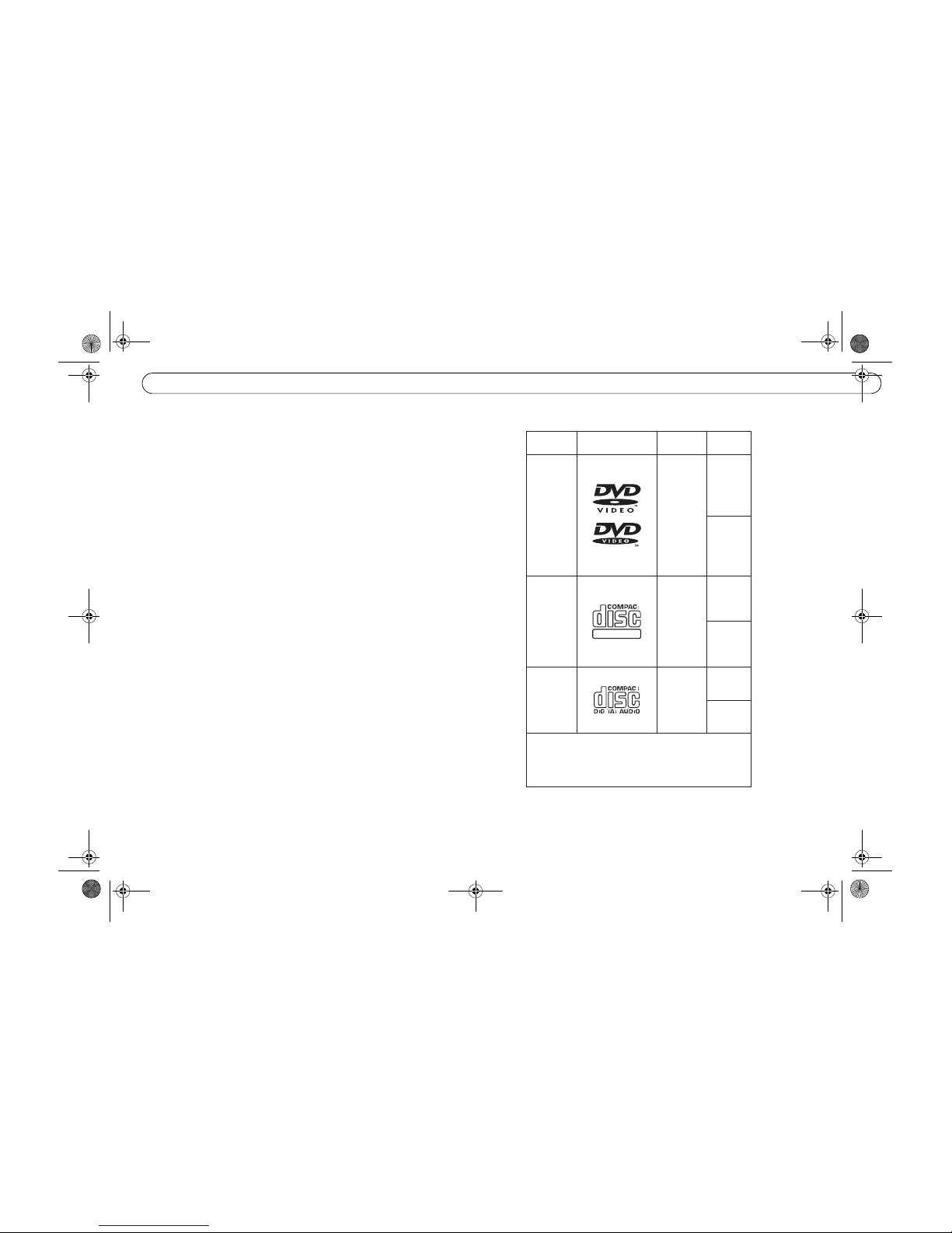
PLAYABLE DISCS
You cannot play discs other than those listed in the table on the right.
You cannot play DVD-RAM discs or non-standardized discs, etc., even
if they may be labeled as in the table on the right.
This SD-H400 uses the NTSC color system, and cannot play DVD video
discs recorded in any other color system (PAL, SECAM, etc.).
This SD-H400 can play the following discs.
DIGITAL VIDEO
Disc Mark
Contents Disc Size
12 cm
8 cm
video
(moving
pictures)
+
Audio
12 cm
8 cm
Audio
12 cm
8 cm
(CD Single)
video
(moving
pictures)
+
Audio
DVD
video
discs
VIDEO
CDs
Audio
CDs
The following discs are also available.
● DVD-R discs of DVD video format
● CD-R/CD-RW discs of CD-DA format
Some of these discs may be incompatible
Introduction-New.fm Page xi Monday, June 9, 2003 4:48 PM
xii
Notes On Discs
Introduction-New.fm Page xii Monday, June 9, 2003 4:48 PM

CHAPTER
Identification of Controls
Front Panel 2
Rear Panel 3
DVD Display 4
Remote control 5
1
1ControlsIdentification.fm Page 1 Monday, June 9, 2003 2:49 PM
IdentificationChapter 1
2
Identification of Controls
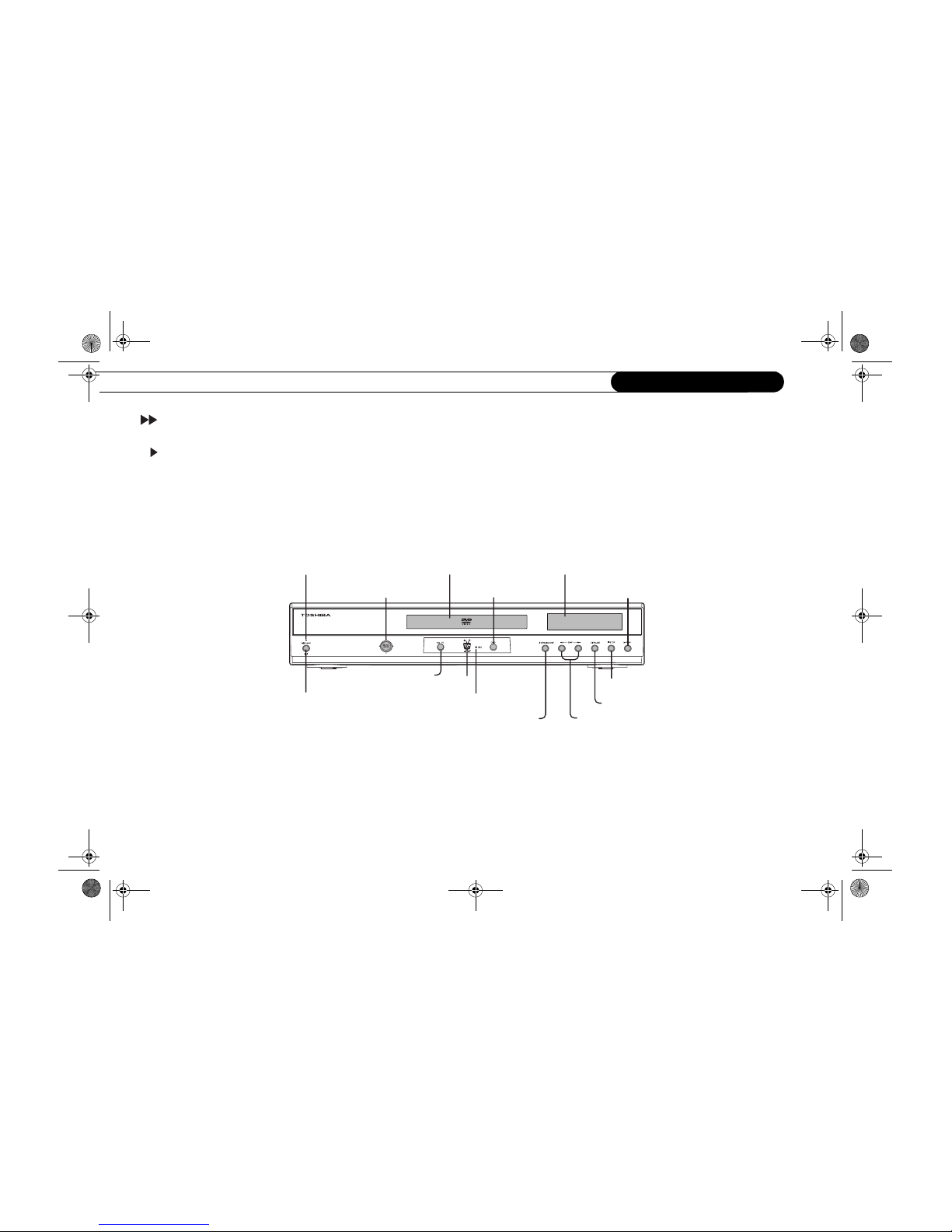
Front Panel
ON/STANDBY indicator
ON/STANDBY button
DVD display
SELECT/ENTER button
Direction buttons/
Live TV button
TiVo button
DVD button
OPEN/CLOSE button
SKIP buttons
STOP button
PLAY button
PAUSE button
Disc tray
REC indicator
1ControlsIdentification.fm Page 2 Monday, June 9, 2003 2:49 PM
Identification of Controls (continued)
3
1
Identification of Controls (continued)
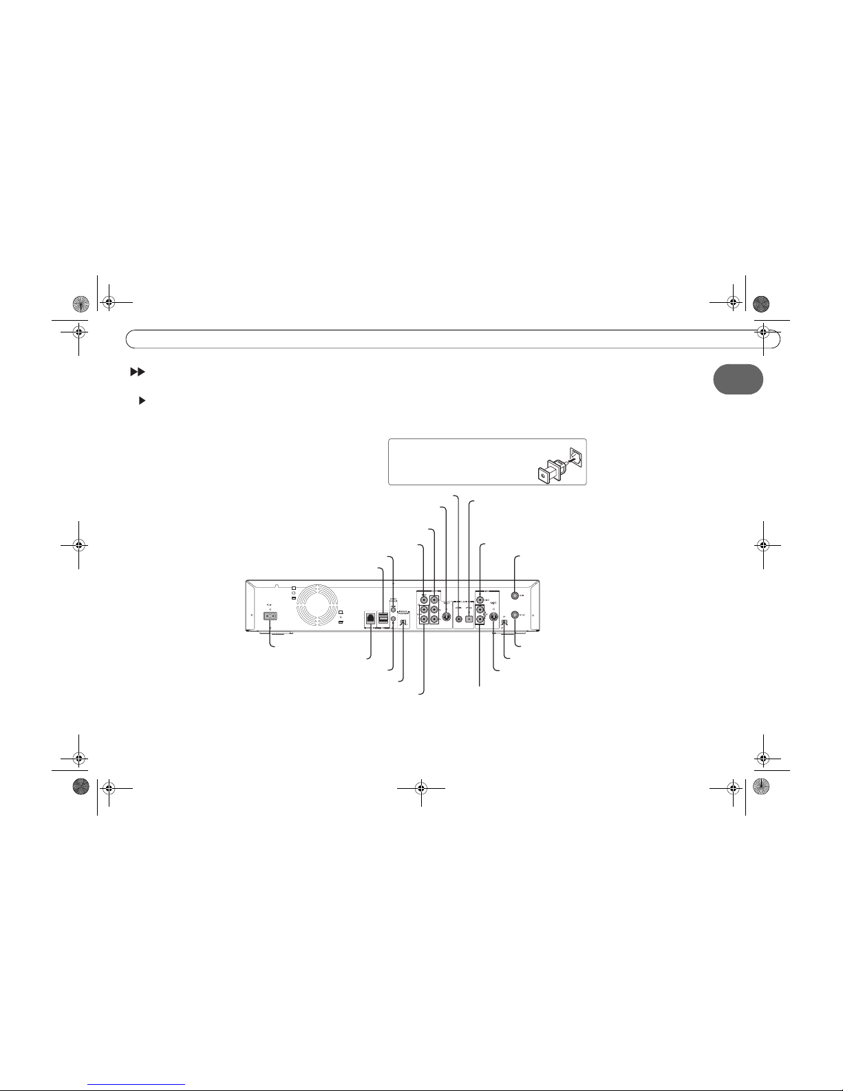
Rear Panel
When connecting the optical digital cable, remove
the cap and fit the connector into the jack firmly.
When not using the jack, keep the cap inserted
to protect it from dust intrusion.
AC IN~ jack
PHONE LINE jack
USB jacks
CHANNEL CHANGE (SERIAL) jack
CHANNEL CHANGE (I/R) jack
INTERLACE/PROGRESSIVE (I/P) switch
ANALOG AUDIO OUT (L/R) jacks
VIDEO OUT (Y/P
B/PR)
(Component video) jacks
S-VIDEO OUT jack
BITSTREAM/PCM COAXIAL (DIGITAL) AUDIO OUT jack
BITSTREAM/PCM OPTICAL
(DIGITAL)
AUDIO OUT jack
VIDEO IN jack
S-VIDEO IN jack
CH (3/4) switch
RF OUT jack
RF IN jack
AUDIO IN (L/R) jacks
VIDEO OUT jack
1ControlsIdentification.fm Page 3 Monday, June 9, 2003 2:49 PM
IdentificationChapter 1
4
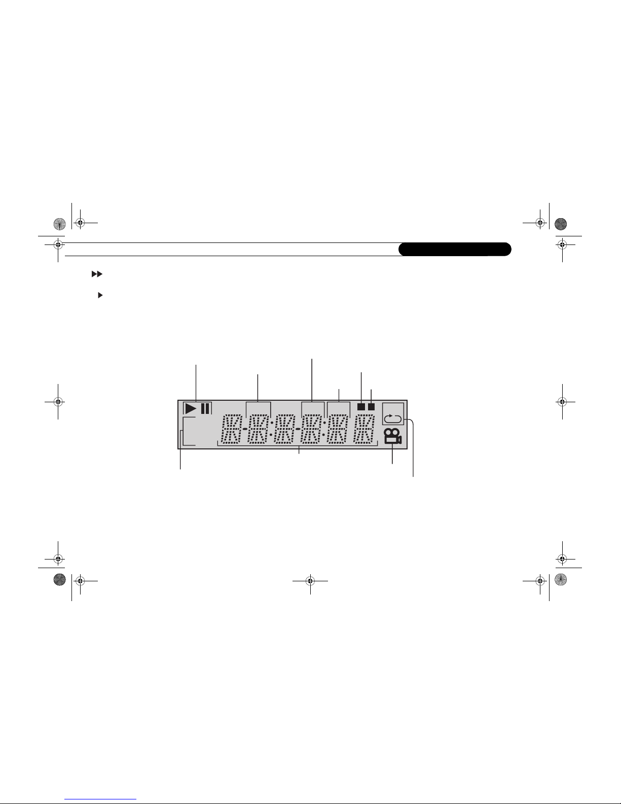
DVD Display
DVD Display
DVD
VCD
TITLE
CHP TRK
M A-BR
Play mode indicator
Title number indicator
Chapter number indicator
DVD/VIDEO CD/CD indicator
Multifunctional indicator (indicates
operating statusor messages, etc.
Memory playback indicator
Track number
indicator Random playback indicato
r
Angle icon indicator
Repeat playback indicato
r
1ControlsIdentification.fm Page 4 Monday, June 9, 2003 2:49 PM
Identification of Controls (continued)
5
1
Identification of Controls (continued)
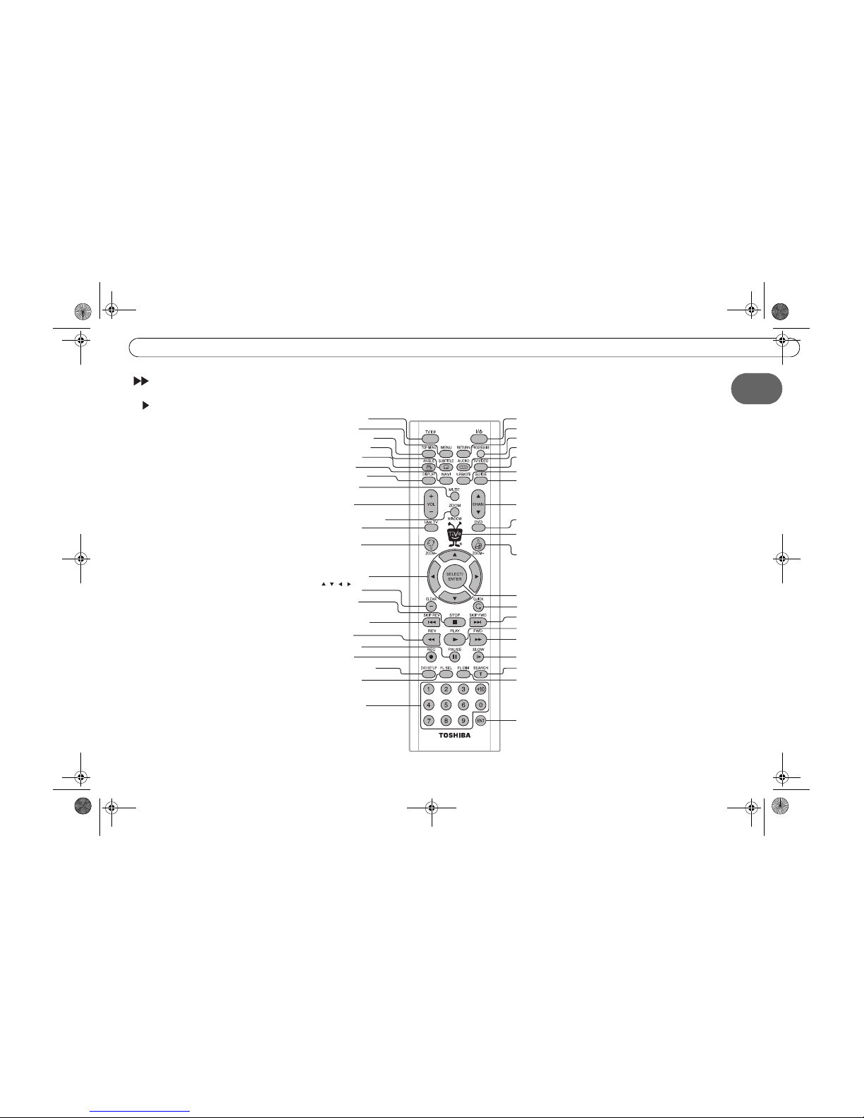
Remote control
TV Power button
MENU button
ANGLE button
SUBTITLE button
TOP MENU button
DISPLAY button
NAVI button
MUTE button
VOL button
ZOOM/WINDOW button
Live TV button
ZOOM- button
Direction buttons
( / / / )
CLEAR button
STOP button
SKIP REV button
REV button
PAUSE button
REC button
DVD SETUP button
FL SEL button
Number buttons
Power button
RETURN button
PROGRESSIVE button
AUDIO button
TV/VIDEO button
V-REMOTE button
GUIDE button
CHAN button
DVD button
ZOOM+ button
SELECT/ENTER button
QUICK button
SKIP FWD button
PLAY button
FWD button
SLOW button
SEARCH button
FL DIM button
ENT button
TiVo button
1ControlsIdentification.fm Page 5 Monday, June 9, 2003 2:49 PM
IdentificationChapter 1
6
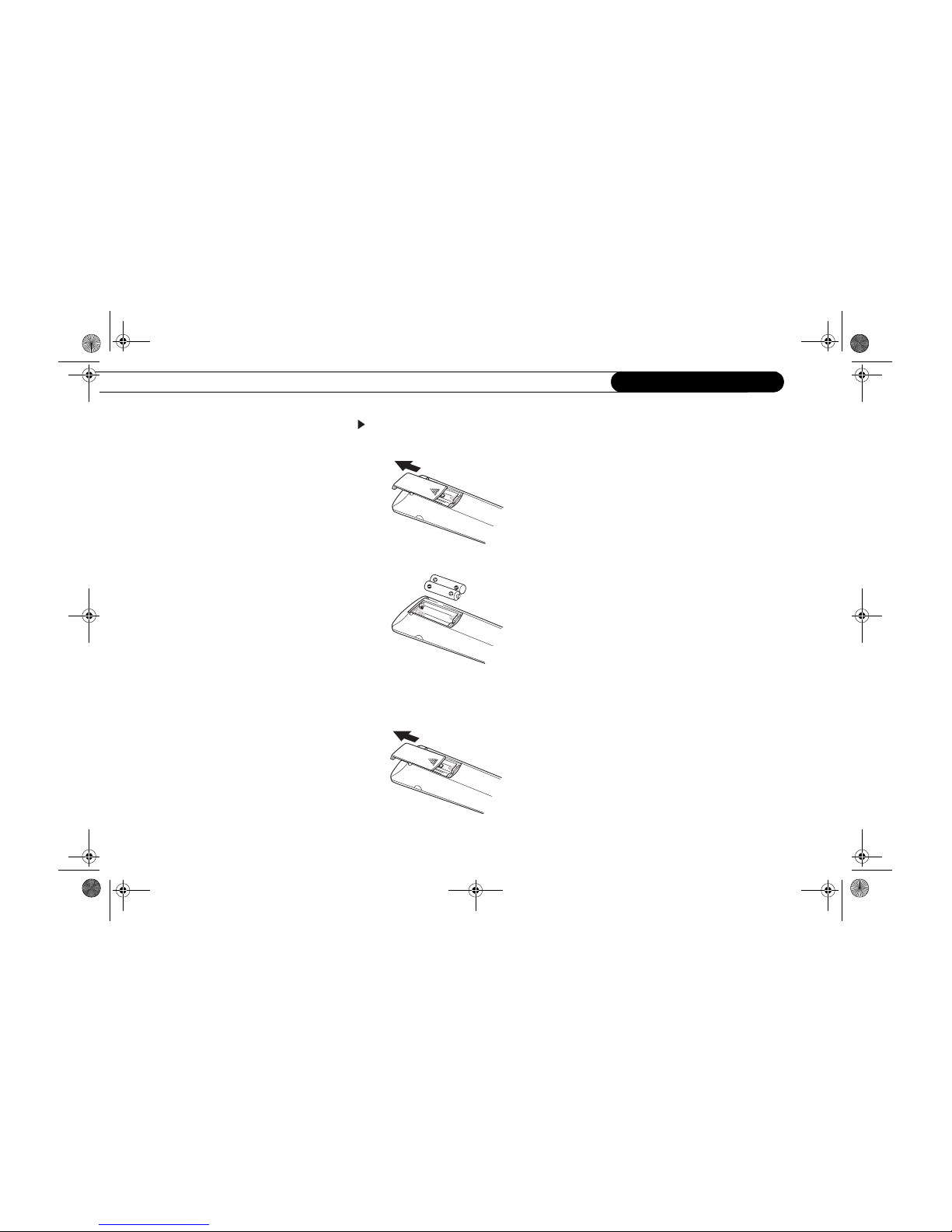
Loading batteries
1. Open the cover.
2. Insert batteries (AAA size).
Make sure to match the + and – on the batteries to the marks inside the battery
compartment.
3. Close the cover.
Notes on batteries
• Improper use of batteries may cause
battery leakage and corrosion. To operate
the remote contro l correctly, follo w the
instructions b elow.
• Do not insert batteries into the remote
control in the wrong direction .
• Do not charge, heat, open, or shortcircuit the batt eries. Do not throw
batteries into a fire.
• Do not leave dead or exhausted batteries
in the remote control.
• Do not use different types of batteries
together, or mix old and new batteries.
• If you do not use the remote control for a
long period of time, remove the batteries
to avoid possible damage from battery
corrosion.
• If the remote control does not function
correctly or if th e operating range
becomes reduced, replace all batterie s
with new ones.
• If battery leakage occurs, wipe the
battery liquid from the battery
compartment, th en insert new batteri es.
1ControlsIdentification.fm Page 6 Monday, June 9, 2003 2:49 PM
Identification of Controls (continued)
7
1
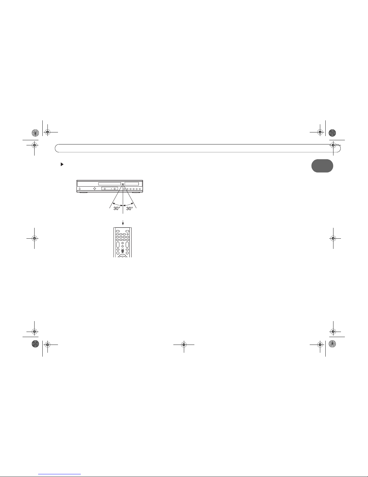
Operating with the remote control
Point the remote control at the remote sensor and press the buttons.
Distance: About 7 m (23 feet) from the front of the remote sensor
Angle: About 30° in each direction of the front of the remote sensor
Do not expose the remote sensor of the SD-H400 to a strong light source such as direct sunlight or
other illumination. If you do so, you may not be able to operate the SD-H400 via the remote control.
Notes on the remote control
• Direct the remote control a t the remote
sensor of the SD-H400.
• Do not drop or give the remote control a
shock.
• Do not leave the remote control near an
extremely hot or humid plac e.
• Do not spill water or put anything wet on
the remote contro l.
• Do not open the remote control.
1ControlsIdentification.fm Page 7 Monday, June 9, 2003 2:49 PM
IdentificationChapter 1
8
1ControlsIdentification.fm Page 8 Monday, June 9, 2003 2:49 PM

CHAPTER
Getting Started
Using This Guide 10
Cables and Accessories 11
Connecting the Phone Line 12
Using Your SD-H400 with a Cable or Satellite Box 13
2
2GettingStarted-New.fm Page 9 Monday, June 9, 2003 2:51 PM
Getting StartedChapter 2
10
Using This Guide
Finding your setup connections example
This guide provides examples of connecting the SD-H400 Digital Media Server (SD-
H400) to an existing antenna, cable, or satellite system and other A/V equipment.
Choose your setup connections from the ones below:
What’s next?
After connecting your SD-H400, the last steps are to activate the TiVo service and
complete Guided Setup. See the TiVo Viewer’s Guide for help with these steps.
You use either antenna or cable without a
cable box. You may also have a VCR.
Setup 1: Connecting to TV and Optional
VCR.
p. 18
You use cable and want to watch one
channel while recording another.
Setup 1: Watching one channel while
recording another (antenna or cable only).
p. 19
You have either a cable or satellite box (if
you have both, see Setup 2, instead). You
may also have a VCR.
Setup 2: Connecting to cable or satellite
box (Refer to Setup 1 for optional VCR).
p. 21
You have both a satellite box and antenna,
or both a satellite box and cable without a
cable box.
Setup 2: Connecting to cable or satellite
box (Refer to Setup 1 for optional VCR).
p. 21
You have both a satellite box and cable
with a cable box.
Setup 2: Connecting to both a satellite and
a cable box.
p. 21
You have an advanced home entertainment
system with several components.
Setup 3: Connecting toA/V receiver, game
console, and VCR.
p. 23
You want to enjoy high quality dynamic
sound.
Setup 4: Connecting to Optional Audio
Equipment.
p. 25
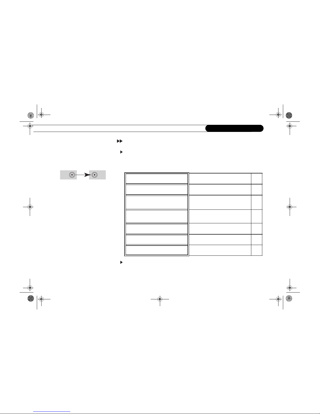
Remember, always connect cables from the
OUT connector of one device to the IN
connector of the nex t. Never connect an IN
to an IN or an OUT to an OUT.
OUT IN
The SD-H400 is not designed to support a
heavy load, such as a TV. Your SD-H400 is
only capable of supporting the weight of one
or two common A/V com ponents such as
VCRs or A/V receivers (provide d they have
four good, broad, padded feet that distrib ute
of the weight near the corners of the SD-
H400).
Also, avoid stacking your SD-H400 on top
of other electronic componen ts—such as
VCRs, A/V receivers—or the vents of your
TV.
2GettingStarted-New.fm Page 10 Monday, June 9, 2003 2:51 PM
Cables and Accessories
11
2
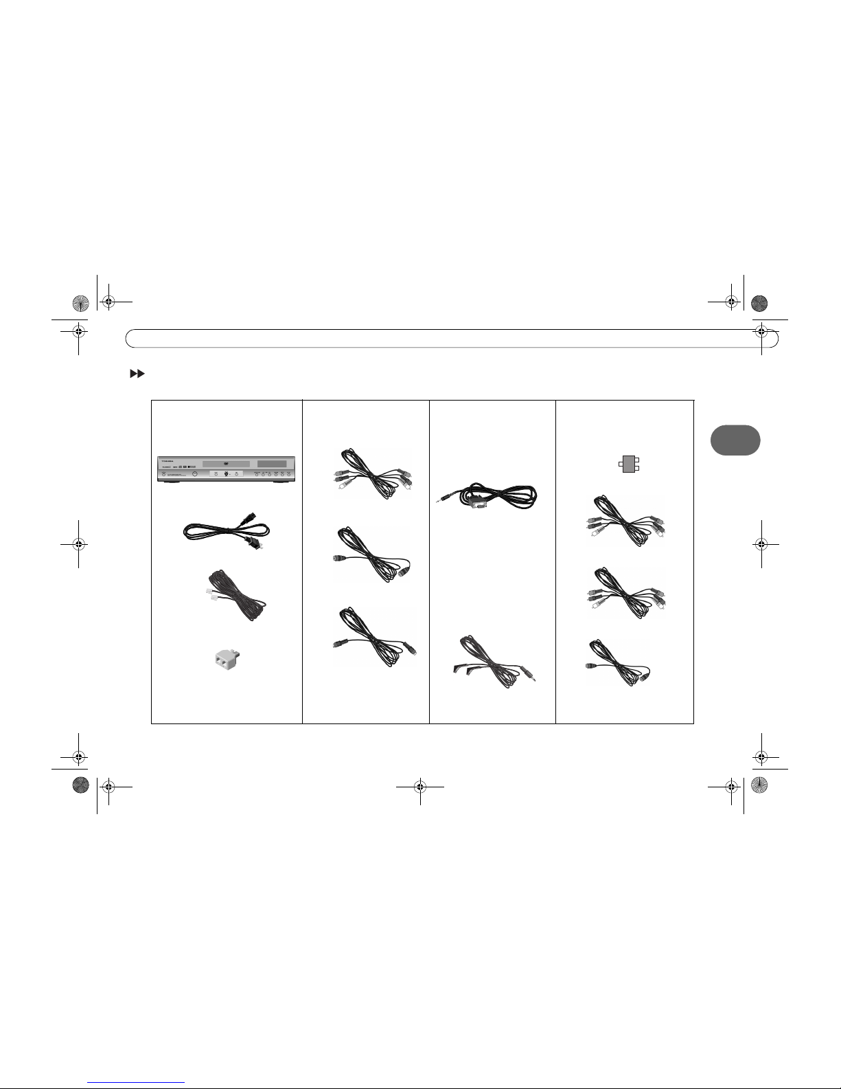
Cables and Accessories
IN
OUT
OUT
SD-H400 DM Server
25’ Phone Cord
Power Cord
Composite A/V Cables
1. These are the basics:
If you have a satellite box
and can’t use the Serial
Control cable above, or if
you have a cable box,
use this cable instead:
2. Choose a video cable:
Serial (Data) Control* Cable
IR Control Cable*
Phone Line Splitter
4. You may need to purchase
these additional items for
some setups:
RF Coaxial Cable Splitter
Extra Composite A/V Cables
3. If your DIRECTV
satellite receiver has a Data
connector, use this cable:
Extra RF Coaxial Cable
RF Coaxial Cable
S-Video Cable
Component Video Cables
*See page 13 for more information and tips ab out Serial and IR Control.
2GettingStarted-New.fm Page 11 Monday, June 9, 2003 2:51 PM

Getting StartedChapter 2
12
Connecting the Phone Line
You don’t need to install a new phone jack or phone number—simply use the phone line
you already have. The following information applies to all setups described in this guide:
• Phone line. Almost every household phone line is a standard analog line, which is
what the SD-H400 requires. Do not connect the SD-H400 to a digital PBX phone
system (these allow many phones to share a single telephone number and are usually
used in hotels and office buildings). Doing so may permanently damage your SD-
H400’s modem and will void your warranty.
• Phone jack. If the phone jack isn’t close to the SD-H400, you can use the 25-foot
phone cord that comes with the SD-H400 to connect it to a phone jack. Phone cords
longer than 25 feet are readily available at most hardware or electronics stores.
Your cable or satellite box may require a connection to your phone line, too. To
connect both the SD-H400 and your cable or satellite box to the same phone jack, use
the provided phone line splitter in the phone jack.
We recommend leaving the phone cord plugged in continuously. If this is inconvenient,
use one of the following solutions:
• Plug in the cord and make the SD-H400 call manually. Do this once or twice a week.
(See page 50 for details.)
• Purchase a wireless modem jack. Many of our customers report success when using
wireless modem jacks. If you purchase one, make sure it is a wireless modem jack, not
merely a wireless phone jack. We cannot guarantee that a wireless modem jack will
work with all phone and electrical systems. (See page 49 for more information.)
25’ Phone Cord
2GettingStarted-New.fm Page 12 Monday, June 9, 2003 2:51 PM
Using Your SD-H400 with a Cable or Satellite Box
13
2
Using Your SD-H400 with a Cable or Satellite Box
Your SD-H400 needs to be able to change the channel in order to record programs and
display live TV. If you are using a cable or satellite box, the SD-H400 must send it signals
to change the channel. (If you use antenna or cable without a cable box, the SD-H400 does
not need a Control cable to change channels.)
These signals can be sent through either an IR (infrared) or a Serial (data) Control cable
connection. The setup examples in Chapter 3 explain how to connect the IR and Serial
Control cables. You may find the following additional tips helpful:
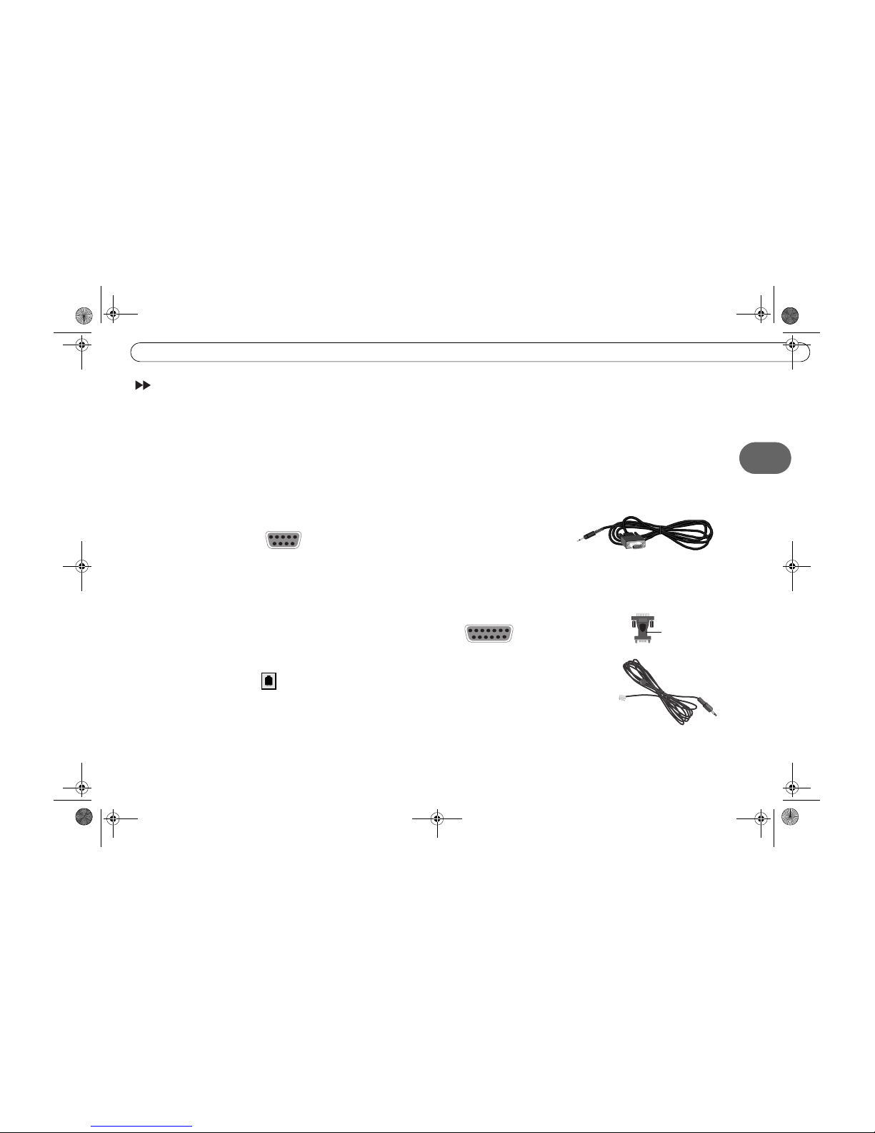
Serial/Data Control
If you have DIRECTV satellite service and your DIRECTV satellite receiver has a 9-pin
data connector like this: , you can connect the Serial Control cable. If you don’t
have DIRECTV, or there is no data connector, you can use the IR Control cable (described
on the next page).
However, some DIRECTV satellite receivers have alternative connections that you may
be able to try. You will need to purchase an additional cable or accessory for these types of
connections:
• If your DIRECTV satellite receiver has a 15-pin connector like this: ,
you can connect the Serial Control cable by using a 15-pin adapter.
• Some RCA satellite receivers for the DIRECTV service have a Home Control
connector like this: (similar to a phone jack, but slightly smaller).
Home Control is the fastest and most reliable form of Control cable connection. To
connect the Home Control cable, plug one end of the cable into the Home Control
jack on your DIRECTV satellite receiver. (If the cable doesn’t fit, don’t force it in.
You could be trying to force a Home Control cable into a phone jack!) Plug the other
end into the Channel Change-Serial jack on the SD-H400.
After setting up your SD- H400, including
the Control cable connection , change
channels with your SD-H400’s remote
control only.
15-pin adapter
(not included)
Home Control cable
(not included)
Serial Control Cable
2GettingStarted-New.fm Page 13 Monday, June 9, 2003 2:51 PM
Getting StartedChapter 2
14
IR (infrared) Control
Finding the IR sensor: To correctly position the IR Control cable, you need to find your
cable box or satellite box’s IR sensor (connection is fully described in the examples in
Chapter 3). To locate the IR sensor, look for a tiny round bulb behind the dark, translucent
plastic “window”—the IR window—on the front of your cable or satellite box. A
flashlight might help you see it. Position the IR emitters so they are centered on the IR
sensor and stick out about 1.5 inches.
Choosing an IR code in Guided Setup: After setting up your SD-H400, you’ll complete
Guided Setup (see the TiVo Viewer’s Guide for more information). During Guided Setup,
you’ll be asked to test and select an IR code. Each IR code signals a particular cable or
satellite box model to change channels. If none of the codes changes the channel on your
particular cable or satellite box, see page 53 for troubleshooting tips. If you find a code or
codes that work, but none of the codes is reliable or consistent, try optimizing the IR
Control connection (see below).
Optimizing the IR Control connection: The IR Control cable works better if its emitters
and the IR window on the cable or satellite box are shaded from other infrared signals.
You can create an IR cover to decrease the interference from other signals. This solution
may help if changing channels with an IR Control cable is unreliable or inconsistent, but
not if channels don’t change at all.
Test whether an IR cover might be effective simply by draping a magazine, a towel, or a
dark cloth over the front of cable or satellite box, including the IR emitters. (See the
diagram on page 15.) Do not block the SD-H400’s IR window. Try changing channels
several times with the SD-H400 remote. If channels change more reliably this way, you
may want to make an IR cover.
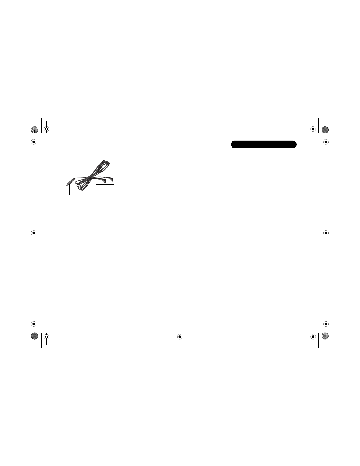
IR Control cable
These IR emitters
send signals to the
IR sensor on your
cable or satellite
box.
This purple end plugs
into your SD-H400.
The small “bulbs” on the IR emitters do not
visibly light up when they send an IR sig nal.
If you find that channels are not ch anging,
see page 52 for troubleshooting help. If
channels change unrel iably or inconsistently,
try the tips on optimizing the IR Control
connection (right).
2GettingStarted-New.fm Page 14 Monday, June 9, 2003 2:51 PM
Using Your SD-H400 with a Cable or Satellite Box
15
2
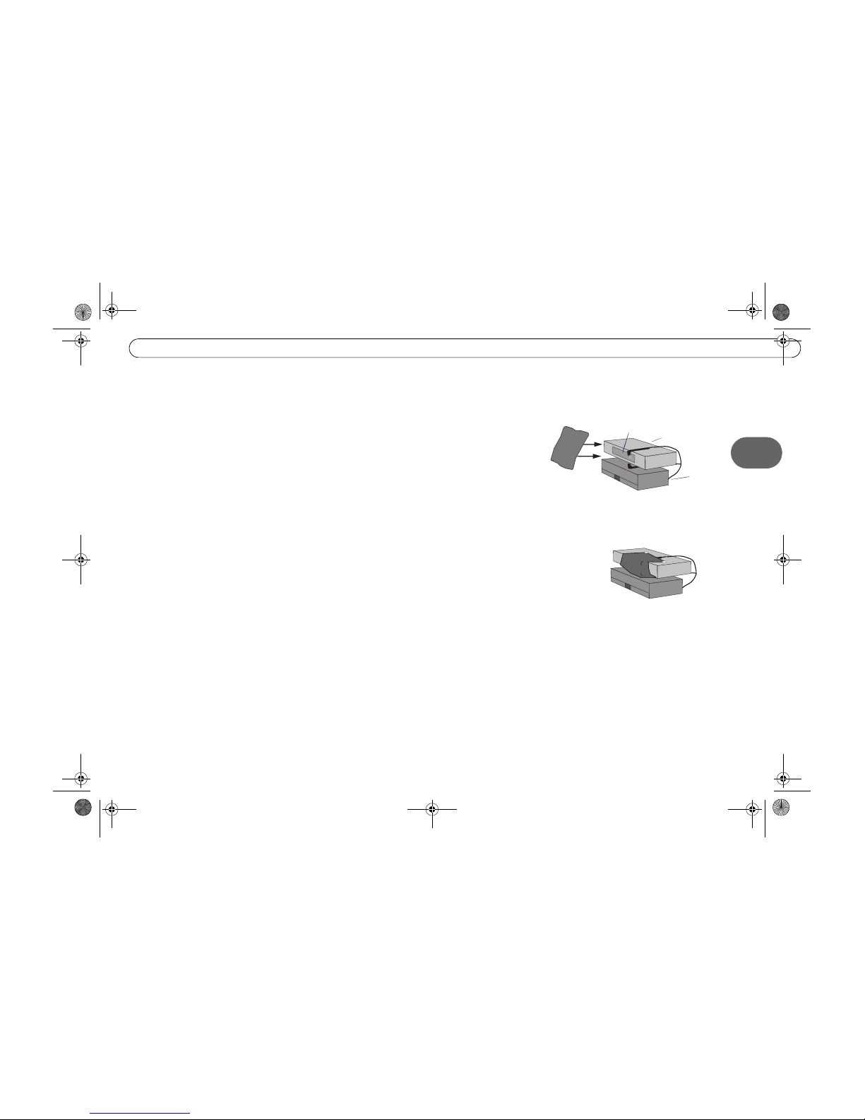
The exact methods and materials you use to build the IR cover will depend on the shape of
your cable or satellite box’s IR window and the materials you have available. However,
the general procedure described below will guide you.
1. Cover the area around the IR emitters and the cable or satellite box’s IR window with a
piece of thick fabric, such as black flannel. You could create a cover using cardboard
or opaque tape instead. The important point is that the material you use fits snugly over
the area around the translucent IR window and the IR Control cable’s emitters.
If possible, cover the entire IR window on the cable or satellite box, because signal
interference can enter from anywhere in the window. For some cable and satellite
boxes, covering the entire IR window will include covering the controls on the front.
In that case, you won’t be able to use the controls, nor will you be able to control the
cable or satellite box with its remote. However, we recommend using only your SD-
H400 remote to change the channel. If you still need to access your cable or satellite
box, use materials that are relatively easy to remove.
2. Secure the cloth, tape, or other material (with tape or by another method), making sure
that it fits closely around the IR window and the IR Control cable’s emitters.
cable or
satellite box
DM Server
IR window
1. Place a piece of opaqu e material—for example,
cloth or tape—over the IR emitters (shown on
opposite page) and the IR window of the c able or
satellite box.
2. Secure the material, making sure that it fits
snugly.
2GettingStarted-New.fm Page 15 Monday, June 9, 2003 2:51 PM

Getting StartedChapter 2
16
2GettingStarted-New.fm Page 16 Monday, June 9, 2003 2:51 PM
CHAPTER
Setup Connections
Setup 1: Connecting to a TV and Optional VCR 18
Setup 2: Connecting to a Cable or Satellite Box 21
Setup 3: Connecting to A/V Receiver, Game Console and VCR 23
Setup 4: Connecting to Optional Audio Equipment 25
3
3CommonSetupExamples-New.fm Page 17 Monday, June 9, 2003 2:52 PM
 Loading...