

Page 1

SERVICE MANUAL
DIGITAL VIDEO
DVD VIDEO PLAYER
FILE NO. 813-9906
SUPPLEMENT
SD-9100
– SUMMARY –
This service manual covers only the different points from the service manual, file no. 810-9807,
for model SD-9000 since SD-9100 are basically the same designing as SD-9000.
Please refer to the file no. 810-9807 for other information.
Feb., 2000 s
Page 2
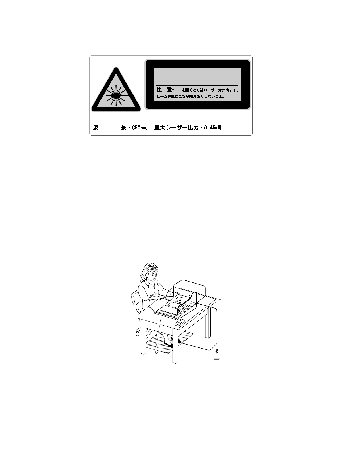
LASER BEAM CAUTION LABEL
VISIBLE LASER RADIATION
CAUTION
WHEN OPEN AND INTERLOCK DEFEATED
DO NOT STARE INTO BEAM.
WAVE LENGTH:650nm, MAX.LASER POWER:0.45mW
98763036
When the power supply is being turned on, you may not remove this laser cautions label. If it removes, radiation of a laser
may be recceived.
PREPARATION OF SERVICING
Pickup Head consists of a laser diode that is very susceptible to external static electricity.
Although it operates properly after replacement, if it was subject to electrostatic discharge during replacement, its
life might be shortened. When replacing, use a conductive mat, soldering iron with ground wire, etc. to protect the
laser diode from damage by static electricity.
And also, the LSI and IC are same as above.
Ground conductive
wrist strap for body.
Soldering iron
with ground wire
or ceramic type
1MΩ
Conductive mat
The ground resistance
between the ground line
and the ground is less than 10Ω.
Page 3

GENERAL DESCRIPTIONS
CONTENTS
SECTION 1
GENERAL DESCRIPTIONS
1. OPERATING INSTRUCTIONS................................................ 1 - 1
General descriptions such as location of mechanical parts and troubleshooting are the same as SD-9000.
Please refer to the service manual for SD-9000 (File No. 810-9807).
SECTION 2
PART REPLACEMENT AND ADJUSTMENT PROCEDURES
Part replacement and adjustment procedures are the same as SD-9000.
Please refer to the service manual for SD-9000 (File No. 810-9807).
SECTION1
SERVICING DIAGRAMS
1. CIRCUIT SYMBOLS AND
SUPPLEMENTARY EXPLANATION..................................... 3- 1
1-1. Precautions for Part Replacement ..................................... 3-1
1-2. Solid Resistor Indication..................................................... 3-1
1-3. Capacitance Indication ....................................................... 3-1
1-4. Inductor Indication ............................................................. 3-2
1-5. Waveform and Voltage Measurement .............................. 3 - 2
1-6. Others ................................................................................... 3-2
1-7. When Replaced ROM ICs or Upgraded Firmware ......... 3 -2
2. PRINTED WIRING BOARD AND
SCHEMATIC DIAGRAM.......................................................... 3-3
SAFETY PRECAUTION ................................................................. 4-1
NOTICE ............................................................................................. 4-1
ABBREVIATIONS ........................................................................... 4-1
1. Integrated Circuit (IC) ............................................................ 4-1
2. Capacitor (Cap) ....................................................................... 4-1
3. Resistor (Res) ........................................................................... 4-1
SECTION 3
3. BLOCK DIAGRAMS.................................................................. 3-5
3-1. Overall Block Diagram .......................................................3-5
3-2. Main Block Diagram ........................................................... 3-7
3-2-1. Logical System Block Diagram...................................... 3-7
3-3. Output Block Diagram........................................................ 3-9
4. CIRCUIT DIAGRAMS........................................................... 3-11
4-1. Output Circuit Diagram................................................3-11
4-2. Sub Video Circuit Diagram .......................................... 3-16
SECTION 4
PARTS LIST
4. EXPLODED VIEWS ................................................................. 4 -2
4-1. Packing Assembly ............................................................. 4-2
4-2. Remote Control Unit........................................................ 4-2
4-3. Chassis Assembly ............................................................... 4-3
4-4. Mechanism Assembly........................................................ 4-4
5 . PARTS LIST ............................................................................... 4 -5
Page 4
SECTION 3
100k
Rated Wattage Type Tolerance
100µ
Temperature
response
Rated
voltage
Tolerance
SERVICING DIAGRAMS
1. CIRCUIT SYMBOLS AND SUPPLEMENTARY EXPLANATION
1-1. Precautions for Part Replacement
• In the schematic diagram, parts marked (ex.
F801) are critical part to meet the safety regulations,
so always use the parts bearing specified part codes
(SN) when replacing them.
1-2. Solid Resistor Indication
Unit None ...........Ω
K ...........kΩ
M ...........MΩ
Tolerance None ...........±5%
B ...........±0.1%
C ...........±0.25%
D ...........±0.5%
F ...........±1%
G ...........±2%
K ...........±10%
M ...........±20%
Rated Wattage (1) Chip Parts
None.........1/16W
(2) Other Parts
None.........1/6W
Other than above, described in the Circuit Diagram.
Type None ...........Carbon film
S ...........Solid
R ...........Oxide metal film
W ...........Metal film
W ...........Cement
FR ...........Fusible
• Using the parts other than those specified shall violate
the regulations, and may cause troubles such as
operation failures, fire etc.
Eg. 1
Fig. 3-1-1
1-3. Capacitance Indication
Symbol
Unit None ...........F
Rated voltage None ...........50V
Tolerance (1) Ceramic, plastic, and film capacitors of which
Temperature characteristic None ........... SL
(Ceramic capacitor) For others, temperature characteristics are
Static electricity capacity Sometimes described with abbreviated letters as
(Ceramic capacitor) shown in Eg. 3.
+
........... Electrolytic, Special electrolytic
NP
...........Non polarity electrolytic
...........Ceramic, plastic
M
...........Film
...........Trimmer
µ ...........µF
p ...........pF
For other than 50V and electrolytic capacitors,
described in the Circuit Diagram.
capacitance are more than 10 pF.
None ...........±5% or more
B ...........±0.1%
C ...........±0.25%
D ...........±0.5%
F ...........±1%
G ...........±2%
(2) Ceramic, plastic, and film capacitors of which
capacitance are 10 pF or less.
None ...........more than ±5% pF
B ...........±0.1 pF
C ...........±0.25 pF
(3) Electrolytic, T rimmer
Tolerance is not described.
described. (For capacitors of 0.01 µF and
no indications are described as F.)
Eg. 2
Fig. 3-1-2
Eg. 3
104
4
pF (0.1µF)
10x10
Temperature characteristic
(or Temperature characteristic+
Static electricity capacity tolerance)
Fig. 3-1-3
SERVICING DIAGRAMS
SECTION 3
3-1
Page 5

1-4. Inductor Indication
Type name
10µ
Type Tolerance
Unit None ...........Η
µ ...........µH
m ...........mH
Tolerance None ...........±5%
B ...........±0.1%
C ...........±0.25%
D ...........±0.5%
F ...........±1%
G ...........±2%
K ...........±10%
M ...........±20%
1-5. Waveform and Voltag e Measurement
• The waveforms for CD/DVD and RF shown in the
circuit diagrams are obtained when a test disc is
played back.
• All voltage values except the waveforms are expressed
in DC and measured by a digital voltmeter.
1-6. Others
• The parts marked with “NC” or “KETU” in the circuit
diagrams are not used for this model.
1-7. When Replaced ROM ICs or Upgraded Firmware
Eg. 4
Fig. 3-1-4
Eg. 5
Fig. 3-1-5
1. When replaced the following ROM ICs, it is necessary
to write the data into the new ICs.
1) IC615 (firmware)
2) IC613 (Setup default data and other information)
2. When the firmware is upgraded, rewriting the new
firmware into IC615 may be requested for servicing.
DATA UPDATE KIT
(RS-232C Interface/cable)
RS-232C
cable
Computer
(MS-DOS/PC-DOS)
3. Connect a computer to the main PC board of the DVD
video player with using DATA UPDATE KIT (P/No.
79080074). (Fig. 3-2-6)
4. Writing operation
Refer to the instruction attached to the data floppy
disc.
MAIN PC Board
DVD video player
Note:
• The firmware and setup data floppy discs are not available as service parts.
For more information, consult TOSHIBA service office in your area.
Fig. 3-1-6
3-2
Page 6
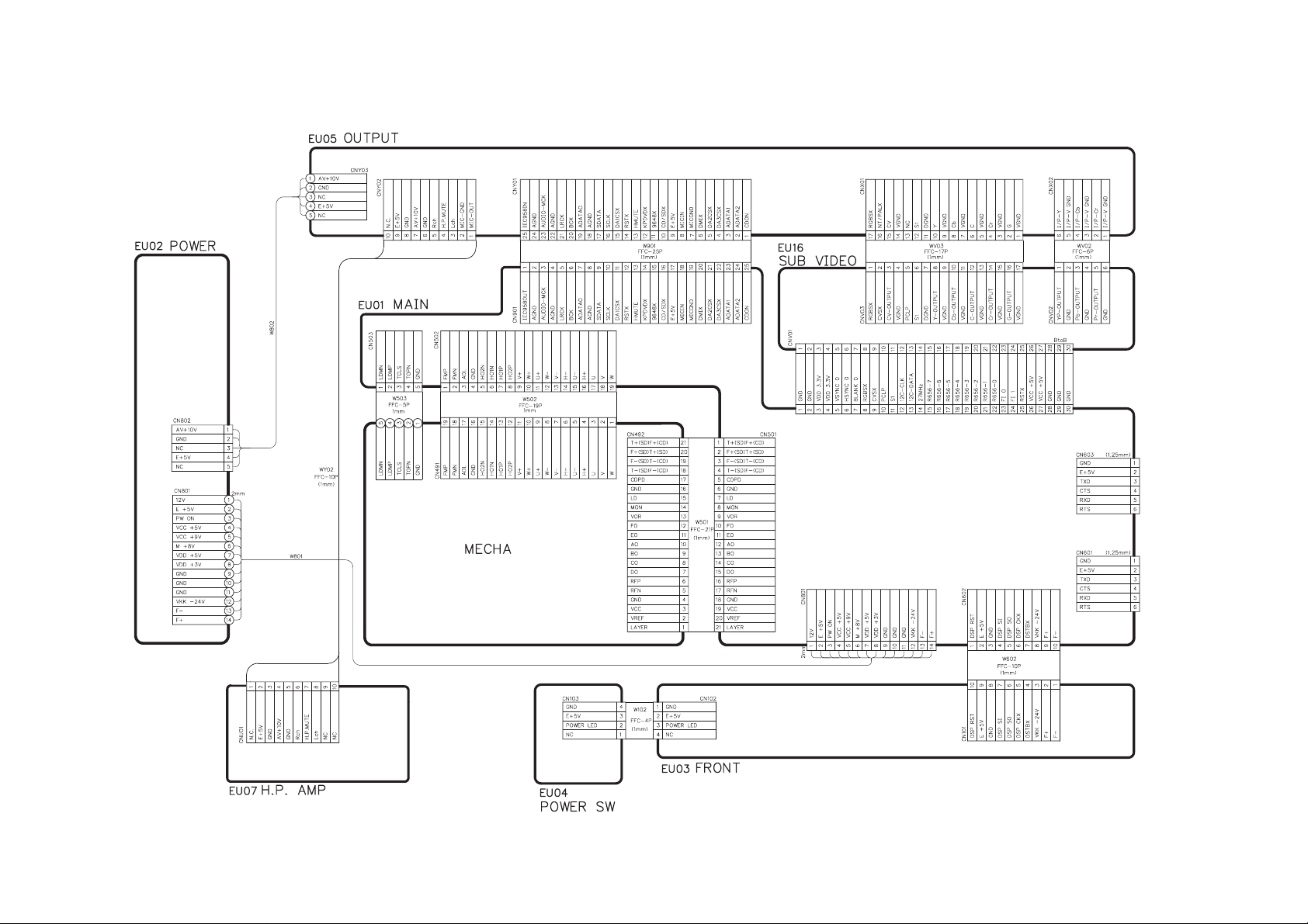
2. PRINTED WIRING BOARD AND SCHEMATIC DIAGRAM
3-3
Fig. 3-2-1
3-4
Page 7

3. BLOCK DIAGRAMS
3-1. Overall Block Diagram
3-5
Fig.3-3-1
3-6
Page 8
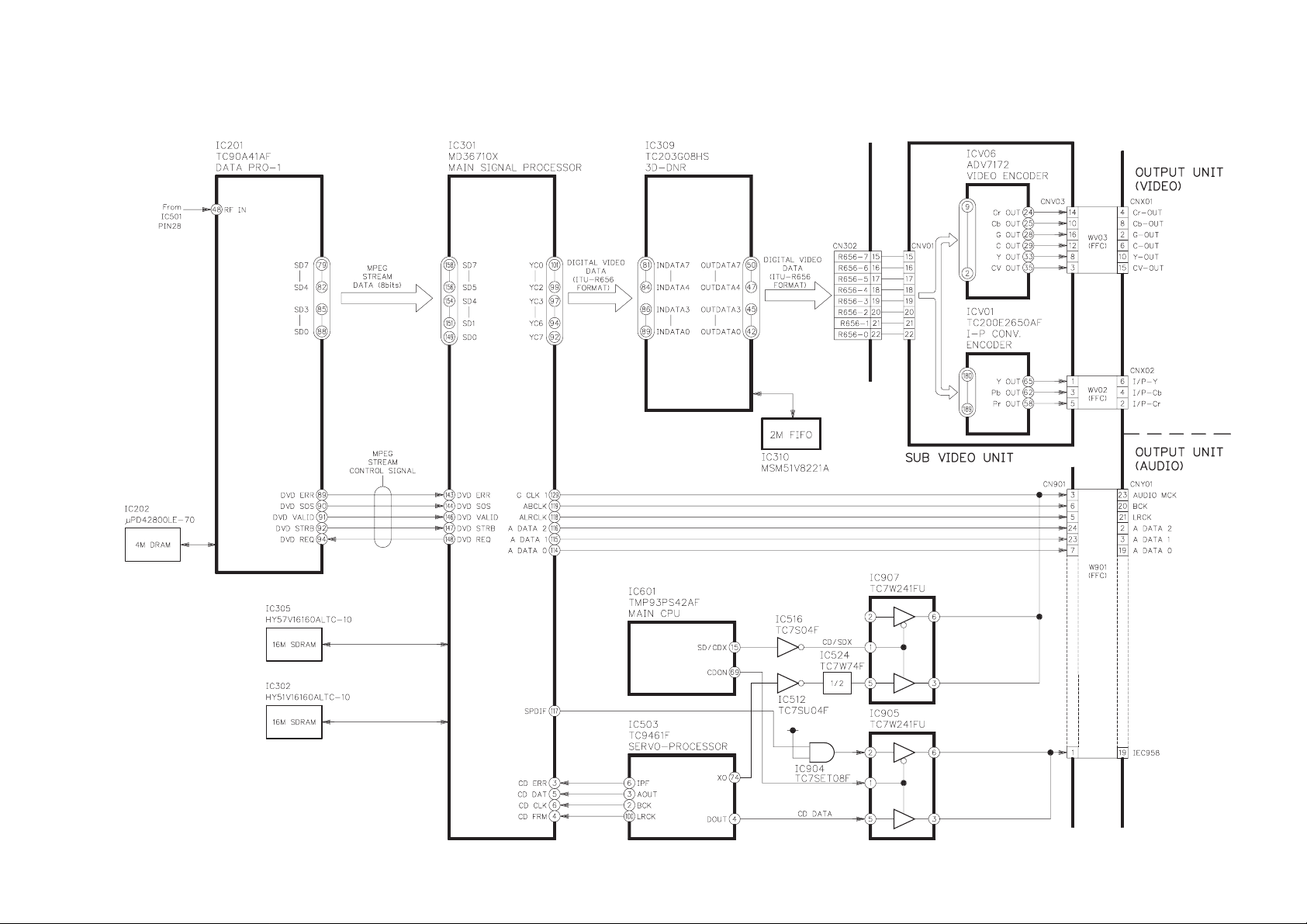
3-2. Main Block Diagram
3-2-1. Logical System Block Diagram
3-7
Fig. 3-3-2
3-8
Page 9
3-3. Output Block Diagram
3-9
Fig. 3-3-3
3-10
Page 10

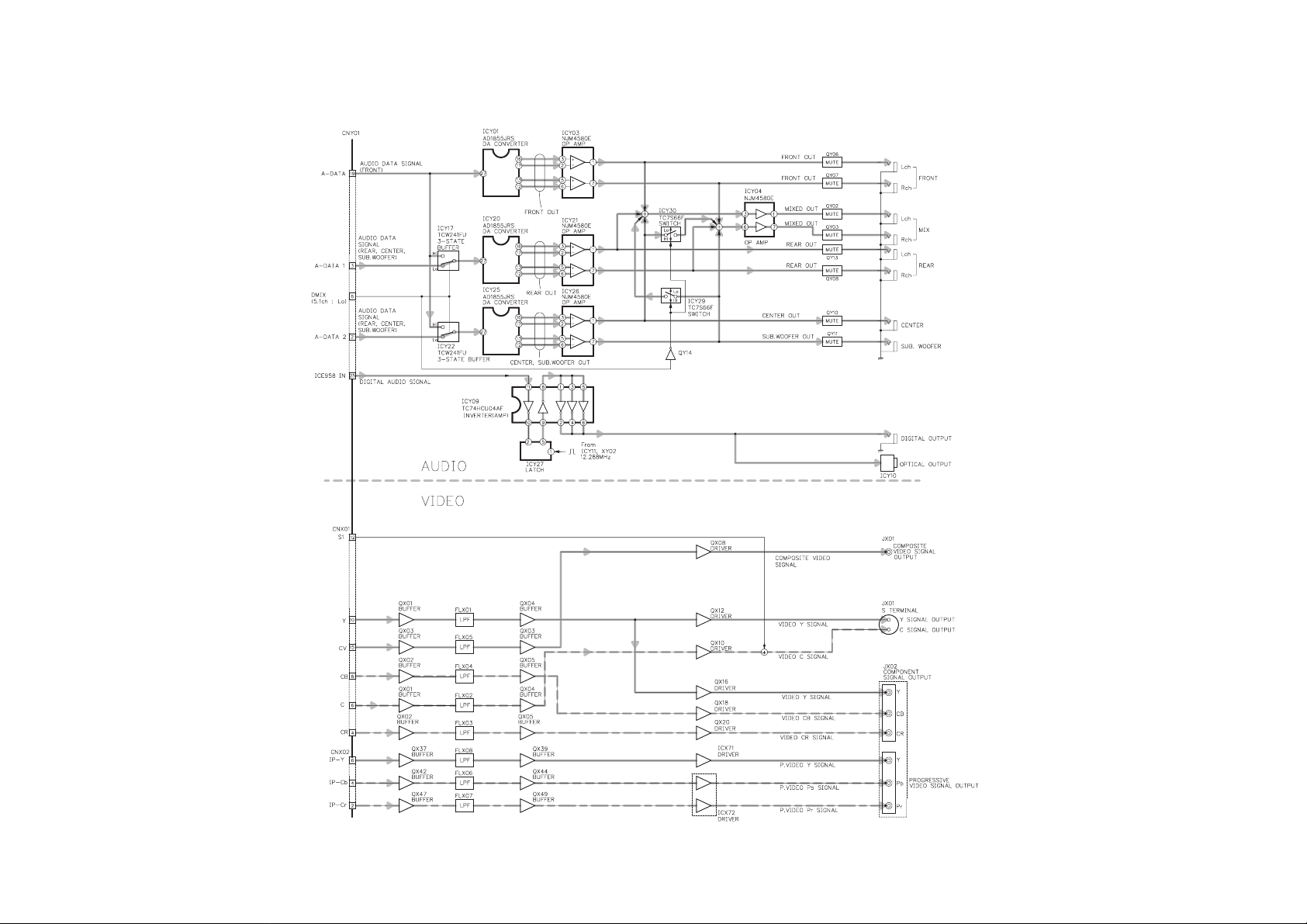
4. CIRCUIT DIAGRAMS
4-1. Output Circuit Diagram
Waveform points
(CNY01)
Pin
Wave
No
No
21
8
20
8
2, 3, 19
8
17
6
16
6
15
6
DAC control
signal
Audio data signal
(Surround)
Digital audio signal
(a)
(b)
(c)
(a)
(b)
(c)
Audio
data
control
signal
Audio data signal
(Front)
Front out
Surround out
MIXED
out
4
(a)
5
(a)
4
(b)
5
(b)
Y signal
Cb signal
Cr signal
C signal
Composit video signal
1
2
3
3
Audio data signal
(Center sub woofer)
Center sub
woofer out
3-11
7
Fig. 3-4-1
3-12
Page 11

4. CIRCUIT DIAGRAMS
4-1. Output Circuit Diagram
Waveform points
(CNY01)
Pin
Wave
No
No
21
8
(a)
20
8
(b)
2, 3, 19
17
16
15
8
(c)
6
(a)
6
(b)
6
(c)
Audio
data
control
signal
Digital audio signal
Audio data signal
(Front)
DAC control
signal
Front out
MIXED
out
Page 12

4
(a)
5
(a)
4
(b)
5
(b)
Page 13

Y signal
Composit video signal
C signal
1
2
Cb signal
3
3
Page 14

Audio data signal
(Surround)
Surround out
Audio data signal
(Center sub woofer)
Center sub
woofer out
Page 15

7
Page 16

Cr signal
Fig. 3-4-2
Page 17

Part Loca No. tion
CNX01 A9
CNX02 J10
CNY01 C1
CNY02 G8
CNY03 B8
CW01 L5
CW02 G2
CW03 A4
CW04 A4
CW05 C2
CW06 C2
CW07 C2
CW08 A6
CW09 B7
CW10 F2
CW11 E4
CW12 J2
CW13 L2
CW14 B6
CW15 B2
CW16 C2
CW17 C2
CX01 A10
CX02 B11
CX03 B11
CX04 A12
CX05 B11
Part Loca No. tion
CX06 A12
CX07 B12
CX08 B13
CX09 B13
CX10 B13
CX11 B15
CX12 B15
CX13 C14
CX14 D12
CX15 C13
CX16 B13
CX17 C15
CX18 D15
CX19 D15
CX20 D15
CX21 E15
CX22 E15
CX23 E15
CX24 E11
CX25 E11
CX26 F15
CX27 G15
CX28 F15
CX29 H10
CX30 H11
CX31 H13
CX32 H14
Part Loca No. tion
CX33 J9
CX34 J10
CX35 J13
CX36 J15
CX37 J13
CX38 J15
CX39 J14
CX40 H15
CX41 K13
CX42 J14
CX43 K13
CX45 K14
CX46 J15
CX47 K15
CX49 L13
CX52 K15
CX53 K14
CX54 G15
CX55 G15
CX56 H15
CX57 H15
CX58 H15
CX59 E15
CX60 B12
CX61 J10
CY01 C3
CY02 C3
Part Loca No. tion
CY03 C3
CY04 C4
CY05 D4
CY06 D4
CY07 E4
CY08 E4
CY09 E2
CY10 D4
CY11 D4
CY12 E4
CY13 E4
CY14 C5
CY15 C5
CY16 C5
CY17 C5
CY18 E5
CY19 E5
CY20 E5
CY21 E5
CY22 D5
CY23 D5
CY24 D5
CY25 D7
CY26 E7
CY27 D7
CY28 D7
CY29 B4
Part Loca No. tion
CY30 B4
CY31 A4
CY32 A5
CY36 B2
CY37 B2
CY38 B2
CY39 B3
CY41 B4
CY42 E5
CY43 D6
CY44 D7
CY45 E7
CY46 G3
CY47 J2
CY48 H4
CY49 H4
CY50 G4
CY51 G4
CY52 G4
CY53 G4
CY54 H4
CY55 H4
CY56 G5
CY57 G5
CY58 G5
CY59 H5
CY60 H5
Part Loca No. tion
CY61 H5
CY62 G5
CY63 H5
CY64 G6
CY65 H15
CY66 G5
CY67 J5
CY68 H15
CY69 K2
CY70 K3
CY71 M2
CY72 K4
CY73 K4
CY74 L4
CY75 L4
CY76 K4
CY77 K4
CY78 L4
CY79 L4
CY80 K5
CY81 K5
CY82 K5
CY83 L5
CY84 L5
CY85 L5
CY86 K5
CY87 M5
Part Loca No. tion
CY88 K5
CY89 L5
CY90 K6
CY91 L5
CY92 G8
CY93 G7
CY94 H8
CY95 H7
CY96 H8
CY97 H7
CY98 J8
CY99 J7
DX01 G10
DX02 G11
DX03 H13
DX04 H14
DX05 F10
DX06 G10
DX07 G10
DX08 C16
DX09 D16
DY01 D6
DY02 G2
DY03 F4
DY04 J2
DY05 L1
EX01 A9
Part Loca No. tion
EX02 A9
EX03 A9
EX04 A9
EX05 B9
EX06 B9
EX07 B9
EX08 B9
EX09 B9
EX10 B9
EX11 B9
EX12 B9
EX13 B9
EX14 B13
EX15 A13
EX16 B12
EX17 C11
EX18 C12
EX19 C11
EX20 D11
EX21 C16
EX22 D15
EX23 D15
EX24 E15
EX25 E15
EX26 E15
EX27 F15
EX28 F15
Part Loca No. tion
EX29 F15
EX30 F15
EX31 F15
EX32 H15
EX33 G16
EX34 H15
EX35 G15
EX36 G15
EX37 H15
EX38 J11
EX39 J11
EX40 K11
EX41 K11
EX42 J13
EX43 K13
EX44 L13
EY01 C1
EY02 D1
EY03 D1
EY04 D1
EY05 D1
EY06 D1
EY07 D1
EY08 D1
EY09 D1
EY10 D1
EY11 D1
Part Loca No. tion
EY12 D1
EY13 E1
EY14 E1
EY15 E1
EY16 E1
EY17 E1
EY18 E4
EY19 E4
EY20 D6
EY21 E5
EY22 A5
EY23 B8
EY24 B8
EY25 A6
EY26 A6
EY27 F8
EY28 F7
EY29 F7
EY30 F7
EY31 F7
EY32 E1
EY33 F7
EY34 G8
EY35 G7
EY36 G7
EY37 H7
EY38 H7
Part Loca No. tion
EY39 H7
EY40 H7
EY41 J7
EY42 J7
EY43 G5
EY44 H5
EY45 K5
EY46 L5
EY47 J4
EY48 M4
EY49 E1
EY50 E1
EY51 E1
EY52 E1
EY53 E1
EY54 A6
EY55 A6
EY56 J3
EY57 L3
EY58 F1
EY59 F4
EY60 J4
EY61 M4
EY62 F3
EY63 F3
EY64 G4
FLX01 B11
Part Loca No. tion
FLX02 C11
FLX03 C11
FLX04 C11
FLX05 D11
FLX06 K12
FLX07 L12
FLX08 J12
FLY01 B7
FLY02 B7
FLY03 B5
ICX71 H14
ICX72 J14
ICX91 C13
ICX92 F11
ICX93 H10
ICY01 D3
ICY02 C3
ICY03 D5
ICY04 D7
ICY05 C7
ICY06 E7
ICY07 E2
ICY08 E3
ICY09 C4
ICY10 A6
ICY11 A2
ICY15 A3
Part Loca No. tion
ICY17 H2
ICY18 J3
ICY19 J3
ICY20 H3
ICY21 H5
ICY22 K2
ICY23 M3
ICY24 M3
ICY25 L3
ICY26 L5
ICY27 A5
ICY28 C2
ICY29 C6
ICY30 E6
ICY31 F2
ICY32 F3
ICY33 B3
JPY02 B5
JX01 C16
JX02 E16
JX03 F16
JY01 G8
JY02 B6
LY01 E1
LY02 E2
LY03 C3
LY04 D4
Part Loca No. tion
LY06 B4
LY07 A6
LY08 G2
LY09 J2
LY10 K4
LY11 G4
LY12 B3
QX01 B10
QX02 C10
QX03 D10
QX04 B12
QX05 C12
QX06 B12
QX07 B13
QX08 B14
QX10 C14
QX12 C14
QX14 D13
QX15 D13
QX16 E14
QX18 F14
QX20 F14
QX22 F13
QX23 E13
QX24 E10
QX25 F10
QX26 F10
Part Loca No. tion
QX27 F10
QX28 F12
QX29 H9
QX31 H11
QX33 H12
QX35 H13
QX37 J11
QX39 J13
QX42 K11
QX44 K13
QX47 L11
QX49 L13
QX52 A11
QX53 B11
QY01 E4
QY02 C8
QY03 E7
QY04 E7
QY05 C6
QY06 F5
QY07 F6
QY08 H6
QY09 M4
QY10 K6
QY11 L6
QY12 J4
QY13 G6
Part Loca No. tion
QY14 E6
QY15 F4
QY16 J4
QY17 M4
QY18 F3
QY19 G3
QY20 G3
QY21 G3
QY22 F4
QY23 F4
QY24 J3
QY25 K2
QY26 L2
QY27 M1
QY28 G7
QY29 C4
QY30 C3
RV01 K15
RV02 K15
RV03 K15
RV05 F10
RV06 A14
RV07 A12
RV10 B10
RV11 C9
RV12 C9
RV13 D9
Part Loca No. tion
RV14 D9
RV15 B10
RV16 C10
RV17 C10
RV18 D10
RV19 D9
RV20 A14
RV21 A14
RV22 A14
RV23 A14
RV24 A14
RV25 B14
RV26 B14
RV27 B14
RV28 B14
RV29 C14
RV30 C14
RV31 D14
RV32 D14
RV33 E14
RV34 E14
RV35 F14
RV36 F14
RV37 J11
RV38 J11
RV39 J11
RV40 K11
Part Loca No. tion
RV41 J11
RV42 K11
RV43 L11
RV44 K11
RV45 L11
RV46 G9
RV47 G10
RV48 G10
RV49 G11
RV50 G12
RV51 G12
RV52 G13
RV53 G14
RV54 J13
RV55 H14
RV57 J15
RV58 J15
RV59 K15
RV60 K15
RV96 C9
RV97 A10
RV98 A10
RV99 D10
RW01 K6
RW02 K6
RW03 L6
RW04 L6
Part Loca No. tion
RW05 K6
RW06 L6
RW07 E5
RW08 G3
RW09 B4
RW10 A5
RW11 C 3
RW12 E6
RW13 C6
RW14 E6
RW15 E3
RW16 F3
RW17 J2
RW18 L1
RW20 F2
RW21 F7
RW22 F7
RW23 E3
RW24 F3
RW25 J3
RW26 M3
RW27 B6
RW28 B6
RW29 F5
RW30 E4
RW31 F4
RW32 F5
Part Loca No. tion
RW33 H6
RW34 J6
RW35 L6
RW36 M6
RW37 G7
RW38 F7
RW39 C4
RW40 C4
RW41 C3
RW42 C3
RW44 A5
RW45 F7
RW46 F7
RX01 A10
RX02 A10
RX03 B10
RX04 B10
RX05 B10
RX06 B10
RX07 C10
RX08 C10
RX09 C10
RX10 C10
RX11 D10
RX12 D10
RX13 D10
RX14 D11
Part Loca No. tion
RX15 C11
RX16 C11
RX17 B11
RX18 B11
RX19 B12
RX20 C12
RX21 C12
RX22 C12
RX23 A11
RX24 A11
RX25 A11
RX26 B12
RX27 A12
RX28 A12
RX29 A12
RX30 B12
RX31 B12
RX32 B12
RX33 B13
RX34 B13
RX35 A12
RX36 A13
RX37 A13
RX38 A13
RX39 A13
RX40 B13
RX41 B12
Part Loca No. tion
RX42 B12
RX43 B12
RX44 B13
RX45 C13
RX46 C13
RX47 C13
RX48 C14
RX49 D13
RX50 D12
RX51 D12
RX52 E13
RX53 A14
RX54 B14
RX55 B14
RX56 B14
RX57 B14
RX58 B14
RX59 C14
RX60 C14
RX61 C14
RX62 D14
RX63 D14
RX64 C15
RX65 C15
RX66 D15
RX67 D15
RX68 D15
Part Loca No. tion
RX69 D15
RX70 D15
RX71 E10
RX72 E10
RX73 E10
RX74 E10
RX75 E10
RX76 F10
RX77 F9
RX78 F9
RX79 F10
RX80 F10
RX81 F10
RX82 F11
RX83 E12
RX84 E12
RX85 E13
RX86 E13
RX87 F13
RX88 F13
RX89 F13
RX90 F13
RX91 F13
RX92 E13
RX93 E13
RX94 F13
RX95 E13
Part Loca No. tion
RX96 D14
RX97 D14
RX98 D14
RX99 E14
RY01 A2
RY02 D1
RY03 D1
RY04 D1
RY05 D3
RY06 C4
RY07 E4
RY08 D5
RY09 E5
RY10 D5
RY11 E5
RY12 D5
RY13 E5
RY14 C5
RY15 E5
RY16 D5
RY17 E5
RY18 C5
RY19 E5
RY20 D6
RY21 E6
RY22 D7
RY23 E7
Part Loca No. tion
RY24 C7
RY25 E7
RY26 E7
RY27 D8
RY28 E7
RY29 D8
RY30 E7
RY31 D8
RY32 E8
RY33 B5
RY34 B5
RY35 A5
RY36 A5
RY37 A6
RY38 B6
RY39 D6
RY40 D7
RY41 F7
RY45 B2
RY46 E7
RY47 E6
RY48 D7
RY49 D7
RY50 F5
RY51 F5
RY52 F6
RY53 F6
Part Loca No. tion
RY54 F6
RY55 G3
RY56 G4
RY57 J4
RY58 G4
RY59 G5
RY60 H4
RY61 H4
RY62 G5
RY63 H5
RY64 G5
RY65 H5
RY66 G5
RY67 H5
RY68 G5
RY69 H5
RY70 G6
RY71 H6
RY72 G6
RY73 H6
RY74 G6
RY75 J6
RY76 G8
RY77 G7
RY78 H8
RY79 H7
RY80 H8
RY81 H7
Part Loca No. tion
RY82 J8
RY83 J7
RY84 K3
RY85 K3
RY86 K4
RY87 M4
RY88 K4
RY89 K4
RY90 L4
RY91 L4
RY92 K5
RY93 L5
RY94 K5
RY95 L5
RY96 K5
RY97 L5
RY98 K5
RY99 L4
RZ01 E14
RZ02 E14
RZ03 F14
RZ04 F14
RZ05 F15
RZ06 E15
RZ07 E15
RZ08 E15
RZ09 E15
RZ10 E15
Part Loca No. tion
RZ11 F15
RZ12 G14
RZ13 G14
RZ14 F15
RZ15 G15
RZ16 G15
RZ17 G15
RZ18 G15
RZ19 G15
RZ20 G15
RZ21 G15
RZ22 G15
RZ23 H15
RZ24 H15
RZ25 H15
RZ26 H15
RZ27 H15
RZ28 G14
RZ29 G14
RZ30 G14
RZ31 G13
RZ32 G13
RZ33 H12
RZ34 G12
RZ35 G12
RZ36 G11
RZ37 G11
RZ38 G11
Part Loca No. tion
RZ39 G10
RZ40 G10
RZ41 G10
RZ42 G9
RZ43 G9
RZ44 J9
RZ45 J9
RZ46 J9
RZ47 A10
RZ48 J11
RZ49 J10
RZ50 J11
RZ51 J11
RZ52 J12
RZ53 J14
RZ54 J15
RZ55 J15
RZ56 J15
RZ57 J12
RZ58 J15
RZ59 J12
RZ60 J12
RZ61 J13
RZ62 J14
RZ63 J13
RZ64 J13
RZ65 J13
RZ66 H15
Part Loca No. tion
RZ67 J15
RZ68 J16
RZ69 J16
RZ70 J15
RZ71 K16
RZ74 J14
RZ75 K13
RZ76 K12
RZ77 K12
RZ78 K13
RZ79 K12
RZ80 K12
RZ81 K13
RZ82 K13
RZ83 K13
RZ84 K13
RZ85 K11
RZ86 K11
RZ87 K11
RZ91 L12
RZ92 L13
RZ93 K11
RZ94 K12
RZ96 L12
RZ97 L12
RZ98 L13
SY01 D6
XY02 B2
3-13
Page 18

1
JX01 Composite video output
C-16
5
CNX01
(a) Pin (Cb)
(b) Pin (C
8
4
B-9
r
)
C-9
2
JX01 S-video output
3
JX02 Y/Cb/Cr output
CVBS output
75Ω terminated
100% color bar
V: 500 mV/div
H: 20 s/div
S-Y/C
75Ω terminated
Y
100% color bar
C
V: 500 mV/div
H: 20 µs/div
Component output
75Ω terminated
Y
100% color bar (Play)
Cb
Cr
V: 500 mV/div
H: 20 µs/div
D-16
E-16
100% color bar (Play)
(a)
(b)
V: 1 V/div
H: 20 µs/div
6
CNY01
(a) Pin (S DATA)
(b) Pin (S CLOCK)
(c) Pin (DA2CSX)
7
17
16
15
(a)
(b)
(c)
V: 5 V/div
H: 20 µs/div
JY01 L ch output / R ch output
L ch output
R ch output
V: 2 V/div
H: 200 µs/div
D-1
D-1
D-1
H-8
4
CNX01
(a) Pin (Y)
(b) Pin (C)
10
6
100% color bar (Play)
(a)
(b)
V: 1 V/div
H: 20 µs/div
CNY01
8
(a) Pin (LRCK)
B-9
(b) Pin (BCK)
C-9
(c) Pin (ADATA)
3-14
21
20
19
(ADATA2)
2
(ADATA1)
3
5.1ch
D-1
D-1
D-1
E-1
E-1
(a)
(b)
(c)
Fig. 3-4-2
Page 19

IC
ICY01
DA CONVERTER
1
2.5
2
4.9
3
3.2
4
3.5
5
6
7
8
9
10
11
2.3
12
2.4
13
2.4
14
15
2.4
16
2.3
17
4.9
18
3.3
19
20
21
22
23
4.9
24
2.4
25
2.4
26
1.3
27
4.9
28
ICY02
REGURATOR
1
6.5
2
3
1.2
4
4.9
5
6.5
ICY03
OP AMP
1
4.9
2
4.9
3
4.9
4
4.9
5
4.9
6
4.9
7
4.9
8
9.2
ICY04
OP AMP
1
4.9
2
4.9
3
4.9
4
5
4.9
6
4.9
7
4.9
8
9.2
ICY17
0
3-STATE
BUFFER
4.7
1
0
2
1.3
3
0
4
1.3
5
1.3
6
4.7
7
4.9
8
ICY18
AND GATE
0
1
0
2
0
3
0
4
4.9
5
ICY19
OR GATE
1
0
2
0
3
0
4
0
5
4.9
ICY20
DA CONVERTER
1
0
2
2.5
3
4.9
4
3.2
5
3.5
6
0
7
0
8
0
9
0
10
0
11
0
12
2.3
13
2.4
14
2.4
15
0
16
2.4
17
2.3
18
4.9
19
3.3
20
0
21
0
22
0
23
0
24
4.9
25
2.4
26
2.4
27
1.3
28
4.9
ICY21
OP AMP
4.9
1
4.9
2
4.9
3
0
4
4.9
5
4.9
6
4.9
7
9.2
8
ICY22
3-STATE
BUFFER
1
4.7
2
0
3
1.3
4
0
5
1.3
6
1.3
7
4.7
8
4.9
ICY23
AND GATE
1
0
2
0
3
0
4
0
5
4.9
ICY24
OR GATE
1
0
2
0
3
0
4
0
5
4.9
ICY07
0
0
0
0
0
0
0
0
0
0
0
0
0
0
AND GATE
0
1
0
2
0
3
0
4
4.9
5
ICY08
OR GATE
1
0
2
0
3
0
4
0
5
4.9
ICY09
INVERTER
2.5
1
2.5
2
2.5
3
2.5
4
2.5
5
2.5
6
0
7
2.5
8
2.5
9
2.5
10
2.0
11
2.6
12
2.0
13
4.9
14
ICY10
D-IN
2.5
VCC
4.9
GND
ICY11
OSCILLATOR
1
4.9
2
0
3
0
4
0
5
0
6
4.9
7
2.5
8
4.9
ICY15
3-STATE
BUFFER
1
0
2
0
3
0
4
0
5
0
6
2.5
7
4.9
8
4.9
ICY25
DA CONVERTER
0
1
2.5
2
4.9
3
3.2
4
3.5
5
0
6
0
7
0
8
0
9
0
10
0
11
2.3
12
2.4
13
2.4
14
0
15
2.4
16
2.3
17
4.9
18
3.3
19
0
20
0
21
0
22
0
23
4.9
24
2.4
25
2.4
26
1.3
27
4.9
28
ICY26
OP AMP
1
4.9
2
4.9
3
4.9
4
0
5
4.9
6
4.9
7
4.9
8
9.2
ICY27
D-FLIP-FLOP
1
2.6
2
2.5
3
2.5
4
0
5
2.5
6
4.9
7
4.9
8
4.9
ICY28
REGURATOR
1
6.5
2
0
3
1.2
4
4.9
5
6.5
ICY29
SWITCH
1
4.9
2
4.9
3
0
4
0
5
9.2
ICY30
SWITCH
4.9
1
4.9
2
0
3
0
4
4.9
5
ICY31
AND GATE
1
0
2
0
3
0
4
0
5
4.9
ICY32
OR GATE
1
0
2
0
3
0
4
0
5
4.9
ICY33
3-STATE
BUFFER
0
1
0
2
0
3
0
4
0
5
2.5
6
4.9
7
4.9
8
ICX71
OP AMP
6.4
1
3.8
2
3.8
3
4
1.9
5
3.8
6
3.8
7
9.3
8
ICX72
OP AMP
6.4
1
3.8
2
3.8
3
4
3.8
5
3.8
6
6.4
7
9.3
8
0
0
Transistor
QY01
SWITCH
4.9
1
4.9
2
4.9
3
0
4
0
5
0
6
QY02
SWITCH
1
0
2
0
3
0
4
0
5
0
6
0
QY03
SWITCH
1
0
2
0
3
0
4
0
5
0
6
0
QY06
SWITCH
1
0
2
0
3
0
4
0
5
0
6
0
QY07
SWITCH
1
0
2
0
3
0
4
0
5
0
6
0
QY08
SWITCH
1
0
2
0
3
0
4
0
5
0
6
0
QY09
SWITCH
1
4.9
2
4.9
3
4.9
4
5
6
QY10
SWITCH
1
2
3
4
5
6
QY11
SWITCH
1
2
3
4
5
6
QY12
SWITCH
4.9
1
4.9
2
4.9
3
4
5
6
QY13
SWITCH
1
2
3
4
5
6
QY18
SWITCH
4.9
1
4.9
2
4.9
3
4
5
6
QY29
REGURATOR
9.2
1
7.4
2
6.5
0
0
0
0
0
0
0
0
0
0
0
0
0
0
0
0
0
0
0
0
0
0
0
0
0
0
0
3
8.2
4
9.2
5
8.2
6
QY30
REGURATOR
9.2
1
7.4
2
6.5
3
8.2
4
9.2
5
8.2
6
QX01
BUFFER
1
1.8
2
1.1
3
0
4
2.1
5
1.4
6
0
QX02
BUFFER
1
2.1
2
1.4
3
0
4
2.1
5
1.4
6
0
QX04
BUFFER
1
2.7
2
2.0
3
0
4
2.4
5
1.7
6
0
QX05
BUFFER
1
2.7
2
2.0
3
0
4
2.7
5
2.0
6
0
QX06
BUFFER
1
9.2
2
2.7
3
2.1
4
9.2
5
2.4
6
1.8
QX07
MIX AMP
BUFFER
1
9.2
2
1.6
3
1.0
4
6.0
5
6.0
6
5.5
QX08
DRIVER
1
—
2
5.4
3
9.2
4
4.7
5
5.4
6
0
QX10
DRIVER
1
3.4
2
2.7
3
0
4
0
5
0
6
0
QX12
DRIVER
1
3.1
2
2.4
3
0
4
0
5
0
6
0
QX16
SWITCH
1
3.1
2
2.4
3
0
4
0
5
0
6
0
QX18
DRIVER
1
2.6
2
2.6
3
4
5
6
QX20
DRIVER
1
2.6
2
2.0
3
4
5
6
QX22
SWITCH
1
2
0.7
3
4
5
0.7
6
QY05
SWITCH
E
C
B
4.7
QY14
SWITCH
E
C
4.7
B
QY15
SWITCH
4.9
E
C
4.9
B
QY16
SWITCH
4.9
E
C
4.9
B
0
0
0
0
0
0
0
0
0
0
0
0
0
0
0
0
0
0
QY17
SWITCH
E
4.9
C
0
B
4.9
QY19
SWITCH
E
4.9
C
0
B
4.9
QY20
SWITCH
E
4.9
C
0
B
4.9
QY21
SWITCH
E
4.9
C
0
B
4.9
QY22
SWITCH
4.9
E
0
C
4.9
B
QY23
SWITCH
E
4.9
C
0
B
4.9
QY24
SWITCH
E
4.9
C
0
B
4.9
QY25
SWITCH
4.9
E
0
C
4.9
B
QY26
SWITCH
4.9
E
0
C
4.9
B
QY27
SWITCH
E
4.9
C
0
B
4.9
QX15
SWITCH
E
C
0/3.3
B
QX23
SWITCH
3.6
E
9.2
C
4.9
B
QX37
BUFFER
E
2.4
C
0
B
1.7
QX39
BUFFER
E
2.1
C
9.3
B
2.7
QX42
BUFFER
E
2.6
C
0
B
1.9
QX44
BUFFER
E
2.2
C
9.3
B
2.9
QX47
BUFFER
2.6
E
0
C
1.9
B
QX49
BUFFER
2.2
E
9.3
C
2.9
B
0
—
3-15
Page 20

2 5 6 7 89
10134
A
B
C
D
E
F
4-2. Sub Video Circuit Diagram
Part Loca No. tion
CNV01 E1
CNV02 E9
CNV03 D1
CV01 F4
CV02 F5
CV03 F6
CV04 E7
CV05 E7
CV06 E7
CV07 E7
CV08 E7
CV09 E7
CV10 E7
CV11 E8
CV12 E8
CV13 D7
CV14 C7
CV15 C9
CV16 B6
CV17 A4
CV18 C4
CV19 C2
CV20 F4
CV21 E3
CV22 F3
CV23 E3
CV24 D3
CV25 D2
CV26 E2
CV27 E2
CV28 E2
CV29 E2
CV30 F1
CV31 E8
EV01 D1
EV02 D1
EV03 D1
EV04 D1
EV05 D1
EV06 D1
EV07 D1
EV08 D1
EV09 D1
EV10 D1
EV11 E1
EV12 E1
EV13 E1
EV14 E1
EV15 E1
EV16 E1
EV17 E1
EV18 E1
EV19 E1
EV20 F1
EV21 F1
EV22 F1
EV23 F1
EV24 F1
EV25 F1
EV26 F1
EV27 F1
EV28 F1
EV29 F1
EV30 F1
EV31 F1
EV32 F1
EV33 G1
EV34 G1
EV35 G1
EV36 G1
EV37 G1
EV38 G1
EV39 G1
EV40 G1
Part Loca No. tion
EV41 G1
EV42 G1
EV43 G1
EV44 F5
EV45 F5
EV46 F9
EV47 F9
EV48 F9
EV49 F9
EV50 F9
EV51 F9
EV52 F3
EV53 E2
EV54 D2
EV55 F4
EV56 F7
EV57 D8
EV58 D8
EV59 E7
EV60 E8
EV61 E8
EV62 E7
FLV01 F4
FLV02 F3
ICV01 D6
ICV02 C3
ICV03 A5
ICV04 D8
ICV05 D8
ICV06 E3
JPV01 F3
JPV02 D1
LV01 F6
LV02 E9
QV01 E8
QV02 E8
QV03 E8
RMV01 F1
RMV02 G2
RMV03 F1
RMV04 F1
RV01 G3
RV02 E8
RV03 E8
RV04 E8
RV05 E8
RV06 E8
RV07 E8
RV08 E7
RV09 E8
RV11 F1
RV12 G2
RV13 G2
RV14 D2
RV15 D2
RV16 D2
RV17 E2
RV18 E2
RV19 E2
RV20 E2
RV21 F1
RV22 E3
RV23 F3
RV24 F3
RV25 F3
RV26 D3
RV27 F1
RV28 D3
RV29 D3
RV30 E4
RV31 E4
TPV01 F3
TPV02 F3
TPV03 E3
G
3-16
NC: Not used.
Fig. 3-4-3
3-17
Page 21

SECTION 4
PARTS LIST
SAFETY PRECAUTION
The parts identified by !( ) mark are critical for safety. Replace only with part number specified.
The mounting position of replacement is to be identical with originals.
The substitute replacement parts which do not have the same safety characteristics as specified in the parts list may create
shock, fire or other hazards.
NOTICE
The part number must be used when ordering parts in order to assist in processing, be sure to include the model number and
description.
ABBREVIATIONS
1. Integrated Circuit (IC)
2. Capacitor (Cap)
• Capacitance Tolerance (for Nominal Capacitance more than 10pF)
Table 4-2-1
Symbol
T olerance %B± 0.1C± 0.25D± 0.5
Symbol
T olerance %
• Capacitance Tolerance (for Nominal Capacitance 10pF or less)
Symbol
Tolerance pFB± 0.1C± 0.25D± 0.5
3. Resistor (Res)
• Resistance tolerance
P
+ 100
0
Q
+ 30
– 10
T
+ 50
– 10
Ex. 10pF G = 10pF ± 2pF
F
± 1
U
+ 75
– 10
Table 4-2-2
F
± 1
Table 4-3-1
G
± 2
V
+ 20
– 10
G
± 2
J
± 5
W
+ 100
– 10
K
± 10
X
+ 40
– 20
Ex. 10MF J = 10µF ± 5%
M
± 20
Y
+ 150
– 10
N
± 30
Z
+ 80
– 20
PARTS LIST
SECTION 4
Symbol
T olerance %B± 0.1C± 0.25D± 0.5
F
± 1
4-1
G
± 2
J
± 5
Ex. 470 ohm J = 470 ohm ± 5%
K
± 10
M
± 20
Page 22

4. EXPLODED VIEWS
4-1. Packing Assembly
4-2. Remote Control Unit
Fig. 4-4-1
Fig. 4-4-2
4-2
Page 23

4-3. Chassis Assembly
Fig. 4-4-3
4-3
Page 24

4-4. Mechanism Assembly
Fig. 4-4-4
4-4
Page 25

LOCATION
4-5
NUMBER
- MECHANICAL PARTS -
M491 79070015 Motor,Feed RF-300PA
MC01 79070158 Chassis Assy,Mechanism
MC03 79070022 Tray
MC04 79070139 Clamper Assy
MC14 79070024 Belt,Loading
MC63 79070028 Screw 2.6x3.5mm
MC65 79070064 Screw 2.6x8W12mm
MP01 79070339 Mechanism Assy Pick Up
MP02 79070023 Chassis,Sub
MP13 79070011 Gear Assy Feed Motor
MP36 79070016 Dumper,Rubber Front
MP37 79070082 Dumper,Rubber Rear
MP61 79070019 Screw 1.7x0.5W9mm
MP64 79070020 Screw 1.7x4.0mm
MP66 79070018 Screw 1.7x4.5mm
MP67 79070017 Washer W-5-1.65
MP90 79070012 Gear A Kit
MP91 79070013 Gear B Kit
MP92 79070014 Gear,Rack
MT491 79040001 Hole Element HW-101A-E
MT492 79040001 Hole Element HW-101A-E
RM01 79070025 Motor Assy,Loading
S491 79070026 Switch SW-SSCF
W102 79080145 Cable,Flexible FFC,4P,L120
W501 79080020 Cable,Flexible FFC,21P,L292
W502 79080021 Cable,Flexible FFC,19P,L185
W503 79080059 Cable,Flexible FFC,5P,L288
W602 79080142 Cable,Flexible FFC-10P-L150
W901 79080178 Cable,Flexible FFC-25P-L180
WV02 79080182 Cable,Flexible FFC,6P,L120
WV03 79080177 Cable,Flexible FFC-17P-L120
WY02 79080183 Cable,Flexible FFC,10P,L440
ZF01 79078001 Remote Control Unit,SE-R0002
ZF02 79078002 Cover,Battery
ZF03 79078003 Cover,Remote Control Unit
! ZF10 79077028 Owners Manual English/SPANISH
ZF17 79070272 Warranty Card USA
ZF20 79070037 Cable,AV
ZF21 79070049 Cable,S
ZF30 79070042 Bag,Polyethylene
ZF31 79080026 Bag,Polyethylene (Power Cord)
ZG01 79071060 Front Panel
ZG03 79071033 Panel,Tray
ZG07 79071034 Knob,HP VR
ZG08 79071035 Button,Power
ZG20 79073014 Cover,Top
! ZG21 79070371 Label,Rating USA
ZG26 79073033 Foot Assy,Front
! ZG27 79070162 Label,PU Caution
ZG33 79079011 Base Main PCB
ZG60 79070165 Screw 3.0x6.0mm
ZK01 79075034 Case
ZK02 79075024 Packing,R
ZK03 79075023 Packing,L
ZK04 79070033 Bag,Polyethylene
ZK06 79075025 Separator
ZZ01 79070274 Test Disc DVDZ-9044
79080074 Kit,Data Update
PART
NUMBER DESCRIPTION
Page 26

LOCATION
C841 79020064 Cap,Electrolytic 39MF M 50V
C842 79020007 Cap,Electrolytic 22MF M 50V
- RESISTORS -
R803 79030045 Res,Oxide Metal 56kohm J 2W
R804 79030025 Res,Oxide Metal 82kohm J 2W
R805 79030039 Res,Carbon 4.7kohm J 1/6W
R806 79030026 Res,Oxide Metal 330kohm J 1W
R807 79030032 Res,Carbon 680ohm J 1/6W
R808 79030011 Res,Oxide Metal 0.47ohm J 1W
R809 79030033 Res,Carbon 3.3kohm J 1/6W
R810 79030028 Res,Oxide Metal 22ohm J 1/2W
R811 79030034 Res,Carbon 2.4kohm J 1/6W
R812 79030035 Res,Carbon 2.7kohm J 1/6W
R824 79030046 Res,Oxide Metal 62ohm J 1/2W
R825 79030036 Res,Carbon 330ohm J 1/6W
R826 79030037 Res,Carbon 7.5kohm G 1/4W
R827 79030038 Res,Carbon 1kohm G 1/4W
R828 79030039 Res,Carbon 4.7kohm J 1/6W
R829 79030004 Res,Carbon 1kohm J 1/6W
R830 79030029 Res,Carbon 100kohm G 1/4W
R832 79030004 Res,Carbon 1kohm J 1/6W
R833 79030047 Res,Oxide Metal 910ohm J 1/2W
R834 79030041 Res,Carbon 2kohm G 1/4W
R835 79030041 Res,Carbon 2kohm G 1/4W
R836 79030041 Res,Carbon 2kohm G 1/4W
R837 79030041 Res,Carbon 2kohm G 1/4W
R838 79030042 Res,Carbon 680ohm G 1/4W
R839 79030041 Res,Carbon 2kohm G 1/4W
R840 79030002 Res,Carbon 10kohm J 1/6W
R841 79030043 Res,Carbon 180ohm J 1/6W
R842 79030042 Res,Carbon 680ohm G 1/4W
R843 79030030 Positive ThermisterPTH8L510-T
R845 79030044 Res,Carbon 2.7kohm G 1/4W
R846 79030039 Res,Carbon 4.7kohm J 1/6W
R847 79030035 Res,Carbon 2.7kohm J 1/6W
R848 79030004 Res,Carbon 1kohm J 1/6W
R849 79030043 Res,Carbon 180ohm J 1/6W
R850 79030009 Res,Oxide Metal 220ohm J 1/2W
- MISCELLANEOUS -
F801 79087001 Fuse 1.6A,250V
F822 79070061 Protector 125V,3.0A
F823 79070061 Protector 125V,3.0A
P801 79088005 Power Cord
RF823 79030017 Res,Fusible 560ohm J 1/2W
T801 79080006 Line Filter 253YOR7
T802 79010013 Power Transformer SRW3020ED-204
EU04 79081011 PC Board Assy Power Switch
EU03 79081010 PC Board Assy Front
- INTEGRATED CIRCUITS -
IC101 79040132 IC TMP47C416F-RE12
- MISCELLANEOUS -
A101 79080148 Display,FL 7-ST-33GK
MT101 79080140 Module,RMT GP1U261X
S101 79080141 Switch Push
S102 79080141 Switch Push
S103 79080141 Switch Push
S104 79080141 Switch Push
S105 79080141 Switch Push
X101 79070006 Oscillator,Ceramic 8MHz
EU07 79081012 PC Board Assy HP AMP
- INTEGRATED CIRCUITS -
ICU01 79040044 IC NJM4580E
- TRANSISTORS -
QU01 79050029 Transistor,Chip IMD3A
QU03 79050038 Transistor,Chip 2SD2114K
QU31 79050001 Transistor,Chip RN2402
QU32 79050001 Transistor,Chip RN2402
QU33 79050001 Transistor,Chip RN2402
QU34 79050038 Transistor,Chip 2SD2114K
QU35 79050038 Transistor,Chip 2SD2114K
- CAPACITORS -
CU01 79020093 Cap,Electrolytic 220MF M 10V
CU02 79020094 Cap,Electrolytic 0.0001MF M 6.3V
CU03 79020094 Cap,Electrolytic 0.0001MF M 6.3V
CU04 79020093 Cap,Electrolytic 220MF M 10V
CU07 79020092 Cap,Electrolytic 10MF M 16V
CU08 79020092 Cap,Electrolytic 10MF M 16V
CU11 79020092 Cap,Electrolytic 10MF M 16V
CU32 79020093 Cap,Electrolytic 220MF M 10V
4-6
NUMBER
- ELECTRICAL PARTS -
EU02 79085011 PC Board Assy Power
- INTEGRATED CIRCUITS -
! Q803 79040100 IC STR-F6535
Q821 79040104 IC UPC1093J
Q830 79040105 IC BA10324A
- TRANSISTORS -
! Q802 79050026 Photo Coupler PC123FY2
! Q804 79050026 Photo Coupler PC123FY2
Q822 79050007 Transistor 2SC3852
Q823 79050007 Transistor 2SC3852
Q824 79050034 Transistor 2SA1757F
Q825 79050005 Transistor 2SC2236-Y
Q827 79050004 Transistor 2SC2458-Y
Q828 79050004 Transistor 2SC2458-Y
Q829 79050008 Transistor RN1201
- DIODES -
! D802 79060016 Diode ERA15-06
! D803 79060016 Diode ERA15-06
! D804 79060016 Diode ERA15-06
! D805 79060016 Diode ERA15-06
! D806 79060009 Diode RU-1P
D807 79060013 Diode AG01
D808 79060015 Diode 1SS133
D809 79060029 Diode,Zener 6.8V
D810 79060013 Diode AG01
D811 79060013 Diode AG01
D812 79060015 Diode 1SS133
D821 79060008 Diode RU2YX
D822 79060017 Diode RU4Z
D823 79060032 Diode RK49LF-L1
D824 79060013 Diode AG01
D825 79060013 Diode AG01
D829 79060015 Diode 1SS133
D831 79060015 Diode 1SS133
D832 79060015 Diode 1SS133
D833 79060015 Diode 1SS133
D835 79060012 Diode ERA15-02
D836 79060007 Diode,Zener UZ3.0BSB
D837 79060004 Diode,Zener UZ5.1BSB
D838 79060004 Diode,Zener UZ5.1BSB
D839 79060004 Diode,Zener UZ5.1BSB
D840 79060006 Diode,Zener UZ5.6BSB
D841 79060013 Diode AG01
D842 79060013 Diode AG01
D843 79060027 Diode,Zener UZ12BSB
- COILS -
! L801 79070051 Coil,Choke ZBF253D-02
! L802 79070051 Coil,Choke ZBF253D-02
! L821 79010001 Coil 20ƒÊH
- CAPACITORS -
! C801 79020027 Cap,Ceramic 0.22MF Z 275V
! C802 79020028 Cap,Ceramic 470pF Z 250V
! C803 79020028 Cap,Ceramic 470pF Z 250V
! C804 79020013 Cap,Ceramic 0.01MF Z 250V
! C805 79020042 Cap,Electrolytic 100MF D 450V
! C806 79020016 Cap,Film 0.033MF J 630V
! C808 79020015 Cap,Ceramic 150pF J 1kV
C809 79020067 Cap,Electrolytic 27MF M 35V
C810 79020078 Cap,Ceramic 470pF K 50V
! C811 79020029 Cap,Ceramic 220pF Z 250V
C812 79020068 Cap,Ceramic 390pF K 2kV
C813 79020079 Cap,Ceramic 2200pF K 50V
C814 79020069 Cap,Film 0.1MF J 50V
C821 79020020 Cap,Electrolytic 820MF M 16V
C823 79020019 Cap,Electrolytic 1200MF M 10V
C825 79020082 Cap,Electrolytic 1500MF M 10V
C826 79020002 Cap,Electrolytic 22MF M 100V
C828 79020077 Cap,Electrolytic 220MF M 25V
C829 79020022 Cap,Electrolytic 220MF M 10V
C830 79020001 Cap,Electrolytic 22MF M 16V
C831 79020043 Cap,Electrolytic 470MF M 16V
C832 79020035 Cap,Electrolytic 100MF M 10V
C833 79020043 Cap,Electrolytic 470MF M 16V
C834 79020043 Cap,Electrolytic 470MF M 16V
C835 79020007 Cap,Electrolytic 22MF M 50V
C836 79020007 Cap,Electrolytic 22MF M 50V
C837 79020021 Cap,Film 0.22MF J 50V
C840 79020064 Cap,Electrolytic 39MF M 50V
PART
NUMBER DESCRIPTION
LOCATION
NUMBER
!
!
!
!
!
!
!
!
!
!
PART
NUMBER DESCRIPTION
Page 27

LOCATION
X301 79089003 Oscillator SMD49,27MHz
X501 79080014 Oscillator SMD49,33.86MHz
X601 79080015 Oscillator CSACV20.00MX040
EU16 79086001 PC Board Assy Progressive
- INTEGRATED CIRCUITS -
ICV01 79040142 IC TC200E2650AF
ICV02 79040128 IC MSM51V8221A
ICV03 79040128 IC MSM51V8221A
ICV04 79040128 IC MSM51V8221A
ICV05 79040066 IC UPC29L33T
ICV06 79040139 IC ADV7172
- TRANSISTORS -
QV01 79050016 Transistor,Chip 2SC2712
QV02 79050016 Transistor,Chip 2SC2712
QV03 79050016 Transistor,Chip 2SC2712
- CAPACITORS -
CV01 79020062 Cap,Electrolytic 47MF M 16V
CV10 79020049 Cap,Electrolytic 10MF M 16V
CV12 79020062 Cap,Electrolytic 47MF M 16V
CV22 79020061 Cap,Electrolytic 100MF M 6.3V
CV31 79020049 Cap,Electrolytic 10MF M 16V
EU05 79085019 PC Board Assy Output
- INTEGRATED CIRCUITS -
ICX71 79040138 IC MC14577CFL1
ICX72 79040138 IC MC14577CFL1
ICY01 79040101 IC AD1855JRS
ICY02 79040102 IC NJM2370U05
ICY03 79040044 IC NJM4580E
ICY04 79040044 IC NJM4580E
ICY07 79040007 IC TC7S08F
ICY08 79040008 IC TC7S32F
ICY09 79040074 IC TC74HCU04AF
ICY10 79080019 Terminal,Optical GP1F32T
ICY11 79040130 IC NJU6321PE-TE1
ICY15 79040087 IC TC7W241FU
ICY17 79040087 IC TC7W241FU
ICY18 79040007 IC TC7S08F
ICY19 79040008 IC TC7S32F
ICY20 79040101 IC AD1855JRS
ICY21 79040044 IC NJM4580E
ICY22 79040087 IC TC7W241FU
ICY23 79040007 IC TC7S08F
ICY24 79040008 IC TC7S32F
ICY25 79040101 IC AD1855JRS
ICY26 79040044 IC NJM4580E
ICY27 79040013 IC TC7W74F
ICY28 79040102 IC NJM2370U05
ICY29 79040072 IC TC7S66F
ICY30 79040072 IC TC7S66F
ICY31 79040007 IC TC7S08F
ICY32 79040007 IC TC7S08F
ICY33 79040087 IC TC7W241FU
- TRANSISTORS -
QX01 79050022 Transistor,Chip HN1A01F-Y
QX02 79050022 Transistor,Chip HN1A01F-Y
QX03 79050022 Transistor,Chip HN1A01F-Y
QX04 79050022 Transistor,Chip HN1A01F-Y
QX05 79050022 Transistor,Chip HN1A01F-Y
QX08 79050015 Transistor,Chip HN1B01F
QX10 79050015 Transistor,Chip HN1B01F
QX12 79050015 Transistor,Chip HN1B01F
QX16 79050015 Transistor,Chip HN1B01F
QX18 79050015 Transistor,Chip HN1B01F
QX20 79050015 Transistor,Chip HN1B01F
QX22 79050032 Transistor,Chip IMX1
QX23 79050030 Transistor,Chip DTC143EKA
QX37 79050018 Transistor,Chip 2SA1162
QX39 79050016 Transistor,Chip 2SC2712
QX42 79050018 Transistor,Chip 2SA1162
QX44 79050016 Transistor,Chip 2SC2712
QX47 79050018 Transistor,Chip 2SA1162
QX49 79050016 Transistor,Chip 2SC2712
QY01 79050012 Transistor,Chip RN4601
QY02 79050014 Transistor,Chip HN1C03F
QY03 79050014 Transistor,Chip HN1C03F
QY05 79050030 Transistor,Chip DTC143EKA
QY06 79050014 Transistor,Chip HN1C03F
QY07 79050014 Transistor,Chip HN1C03F
QY08 79050014 Transistor,Chip HN1C03F
QY09 79050012 Transistor,Chip RN4601
4-7
NUMBER
- MISCELLANEOUS -
JU01 79089009 Jack,HP
VRU01 79030049 Res,Variable
EU01 79083006 PC Board Assy Main
- INTEGRATED CIRCUITS -
IC201 79040110 IC TC90A41AF
IC202 79040061 IC UPD424800LE70
IC202 79040145 IC NN514800AJ-60T
IC203 79040066 IC UPC29L33T
IC204 79040008 IC TC7S32F
IC205 79040008 IC TC7S32F
IC301 79040122 IC MD36710X
IC302 79040063 IC HY57V16160ATC-10
IC305 79040063 IC HY57V16160ATC-10
IC307 79040130 IC NJU6321PE-TE1
IC308 79040011 IC TC7W04F
IC309 79040123 IC TC203G8AF-0101(Z)
IC310 79040128 IC MSM51V8221A
IC311 79040013 IC TC7W74F
IC312 79040119 IC TC7SH86F
IC313 79040119 IC TC7SH86F
IC314 79040119 IC TC7SH86F
IC501 79040114 IC TA1254AF
IC503 79040109 IC TC9461F
IC504 79040006 IC TC7S04F
IC505 79040136 IC BA5917FP-E2
IC506 79040029 IC TC74HC4053AF
IC507 79040039 IC NJM3403AMC
IC508 79040072 IC TC7S66F
IC509 79040129 IC RT2124AFS-T
IC510 79040040 IC BA6844FP
IC512 79040006 IC TC7S04F
IC516 79040006 IC TC7S04F
IC517 79040014 IC TA75S01F
IC518 79040050 IC NJM2107F
IC519 79040009 IC TC7S86F
IC520 79040008 IC TC7S32F
IC521 79040009 IC TC7S86F
IC522 79040011 IC TC7W04F
IC523 79040013 IC TC7W74F
IC524 79040013 IC TC7W74F
IC525 79040121 IC AD8561AR
IC526 79040050 IC NJM2107F
IC527 79040131 IC TC74HC4066AFT
IC528 79040126 IC BU6481KV
IC529 79040125 IC TC7W66FU
IC530 79040072 IC TC7S66F
IC601 79040143 IC TMP93CS42AF-9417
IC602 79040041 IC PST591-IDT
IC603 79040027 IC TC74HC32AF
IC604 79040030 IC TC74AC573F
IC605 79040124 IC TC74HC08AF
IC607 79040007 IC TC7S08F
IC608 79040006 IC TC7S04F
IC609 79040030 IC TC74AC573F
IC613 79040135 IC 24C04AFJA
IC614 79040144 IC W26010AT-15
IC615 79040127 IC LH28F800SGE-70
IC616 79040007 IC TC7S08F
IC617 79040087 IC TC7W241FU
IC902 79040066 IC UPC29L33T
IC904 79040108 IC TC7SET08F
IC906 79040087 IC TC7W241FU
IC907 79040087 IC TC7W241FU
- TRANSISTORS -
Q501 79050019 Transistor,Chip 2SA1182
Q502 79050010 Transistor,Chip RN1411
Q503 79050015 Transistor,Chip HN1B01F
Q504 79050032 Transistor,Chip IMX1
Q505 79050030 Transistor,Chip DTC143EKA
Q506 79050015 Transistor,Chip HN1B01F
Q507 79050037 Transistor,Chip 2SC4944-GR
Q508 79050036 Transistor,Chip 2SA1832-GR
Q511 79050010 Transistor,Chip RN1411
Q512 79050010 Transistor,Chip RN1411
Q601 79050031 Transistor,Chip DTA114EKA
- DIODES -
D501 79060018 Diode,Chip 1SS193
D502 79060018 Diode,Chip 1SS193
D503 79060018 Diode,Chip 1SS193
- MISCELLANEOUS -
PART
NUMBER DESCRIPTION
LOCATION
NUMBER
PART
NUMBER DESCRIPTION
Page 28

LOCATION
CY63 79020089 Cap,Film 220pF J 100V
CY64 79020085 Cap,Electrolytic 100MF M 10V
CY65 79020085 Cap,Electrolytic 100MF M 10V
CY66 79020086 Cap,Electrolytic 220MF M 16V
CY67 79020086 Cap,Electrolytic 220MF M 16V
CY72 79020083 Cap,Electrolytic 10MF M 50V
CY75 79020085 Cap,Electrolytic 100MF M 10V
CY76 79020086 Cap,Electrolytic 220MF M 16V
CY77 79020086 Cap,Electrolytic 220MF M 16V
CY78 79020086 Cap,Electrolytic 220MF M 16V
CY79 79020086 Cap,Electrolytic 220MF M 16V
CY80 79020090 Cap,Film 1000pF J 100V
CY81 79020090 Cap,Film 1000pF J 100V
CY82 79020089 Cap,Film 220pF J 100V
CY83 79020090 Cap,Film 1000pF J 100V
CY84 79020090 Cap,Film 1000pF J 100V
CY85 79020089 Cap,Film 220pF J 100V
CY86 79020086 Cap,Electrolytic 220MF M 16V
CY87 79020086 Cap,Electrolytic 220MF M 16V
CY88 79020089 Cap,Film 220pF J 100V
CY89 79020089 Cap,Film 220pF J 100V
CY90 79020085 Cap,Electrolytic 100MF M 10V
CY91 79020085 Cap,Electrolytic 100MF M 10V
CY92 79020091 Cap,Film 4700pF J 63V
CY93 79020091 Cap,Film 4700pF J 63V
CY94 79020091 Cap,Film 4700pF J 63V
CY95 79020091 Cap,Film 4700pF J 63V
CY96 79020091 Cap,Film 4700pF J 63V
CY97 79020091 Cap,Film 4700pF J 63V
CY98 79020091 Cap,Film 4700pF J 63V
CY99 79020091 Cap,Film 4700pF J 63V
- MISCELLANEOUS -
FLX01 79010008 Coil TH286LAIS15674
FLX02 79010008 Coil TH286LAIS15674
FLX03 79010008 Coil TH286LAIS15674
FLX04 79010008 Coil TH286LAIS15674
FLX05 79010008 Coil TH286LAIS15674
FLX06 79010016 Filter H287LDKS-15818
FLX07 79010016 Filter H287LDKS-15818
FLX08 79010016 Filter H287LDKS-15818
JX01 79089004 Plate,Jack Video
JX02 79089013 Plate,Jack Component
JY01 79089006 Plate,Jack Audio
JY02 79089007 Plate,Jack Digital Audio
SY01 79080018 Relay EG2-9
XY02 79089008 Crystal HC49/U24.576MHz
4-8
NUMBER
QY10 79050014 Transistor,Chip HN1C03F
QY11 79050014 Transistor,Chip HN1C03F
QY12 79050012 Transistor,Chip RN4601
QY13 79050014 Transistor,Chip HN1C03F
QY14 79050030 Transistor,Chip DTC143EKA
QY15 79050001 Transistor,Chip RN2402
QY16 79050001 Transistor,Chip RN2402
QY17 79050001 Transistor,Chip RN2402
QY18 79050012 Transistor,Chip RN4601
QY19 79050001 Transistor,Chip RN2402
QY20 79050001 Transistor,Chip RN2402
QY21 79050001 Transistor,Chip RN2402
QY22 79050001 Transistor,Chip RN2402
QY23 79050001 Transistor,Chip RN2402
QY24 79050001 Transistor,Chip RN2402
QY25 79050001 Transistor,Chip RN2402
QY26 79050001 Transistor,Chip RN2402
QY27 79050001 Transistor,Chip RN2402
QY28 79050014 Transistor,Chip HN1C03F
QY29 79050014 Transistor,Chip HN1C03F
QY30 79050014 Transistor,Chip HN1C03F
- DIODES -
DY01 79060022 Diode,Chip 1SS368
DY02 79060022 Diode,Chip 1SS368
DY03 79060026 Diode UDZS10B
DY04 79060022 Diode,Chip 1SS368
DY05 79060022 Diode,Chip 1SS368
- CAPACITORS -
CW05 79020083 Cap,Electrolytic 10MF M 50V
CW06 79020083 Cap,Electrolytic 10MF M 50V
CW09 79020095 Cap,Electrolytic 1000MF M 25V
CW10 79020086 Cap,Electrolytic 220MF M 16V
CW11 79020086 Cap,Electrolytic 220MF M 16V
CW12 79020086 Cap,Electrolytic 220MF M 16V
CW13 79020086 Cap,Electrolytic 220MF M 16V
CX01 79020039 Cap,Electrolytic 47MF M 10V
CX17 79020088 Cap,Electrolytic 1000MF M 10V
CX20 79020088 Cap,Electrolytic 1000MF M 10V
CX21 79020088 Cap,Electrolytic 1000MF M 10V
CX22 79020033 Cap,Electrolytic 470MF M 6.3V
CX23 79020033 Cap,Electrolytic 470MF M 6.3V
CX37 79020039 Cap,Electrolytic 47MF M 10V
CX38 79020035 Cap,Electrolytic 100MF M 10V
CX40 79020033 Cap,Electrolytic 470MF M 6.3V
CX42 79020039 Cap,Electrolytic 47MF M 10V
CX43 79020039 Cap,Electrolytic 47MF M 10V
CX46 79020033 Cap,Electrolytic 470MF M 6.3V
CX49 79020039 Cap,Electrolytic 47MF M 10V
CX52 79020033 Cap,Electrolytic 470MF M 6.3V
CX53 79020039 Cap,Electrolytic 47MF M 10V
CY10 79020086 Cap,Electrolytic 220MF M 16V
CY11 79020086 Cap,Electrolytic 220MF M 16V
CY12 79020086 Cap,Electrolytic 220MF M 16V
CY13 79020086 Cap,Electrolytic 220MF M 16V
CY14 79020090 Cap,Film 1000pF J 100V
CY15 79020090 Cap,Film 1000pF J 100V
CY16 79020089 Cap,Film 220pF J 100V
CY17 79020086 Cap,Electrolytic 220MF M 16V
CY18 79020090 Cap,Film 1000pF J 100V
CY19 79020090 Cap,Film 1000pF J 100V
CY20 79020089 Cap,Film 220pF J 100V
CY21 79020086 Cap,Electrolytic 220MF M 16V
CY22 79020089 Cap,Film 220pF J 100V
CY23 79020089 Cap,Film 220pF J 100V
CY25 79020085 Cap,Electrolytic 100MF M 10V
CY26 79020085 Cap,Electrolytic 100MF M 10V
CY29 79020084 Cap,Electrolytic 47MF M 25V
CY42 79020085 Cap,Electrolytic 100MF M 10V
CY43 79020085 Cap,Electrolytic 100MF M 10V
CY49 79020085 Cap,Electrolytic 100MF M 10V
CY50 79020083 Cap,Electrolytic 10MF M 50V
CY52 79020086 Cap,Electrolytic 220MF M 16V
CY53 79020086 Cap,Electrolytic 220MF M 16V
CY54 79020086 Cap,Electrolytic 220MF M 16V
CY55 79020086 Cap,Electrolytic 220MF M 16V
CY56 79020090 Cap,Film 1000pF J 100V
CY57 79020090 Cap,Film 1000pF J 100V
CY58 79020089 Cap,Film 220pF J 100V
CY59 79020090 Cap,Film 1000pF J 100V
CY60 79020090 Cap,Film 1000pF J 100V
CY61 79020089 Cap,Film 220pF J 100V
CY62 79020089 Cap,Film 220pF J 100V
PART
NUMBER DESCRIPTION
LOCATION
NUMBER
PART
NUMBER DESCRIPTION
Page 29

SPECIFICATIONS
DVD Video Player/Outputs/Supplied Accessories
[DVD Video Player]
Power supply 120V AC, 60 Hz
Power consumption 25W
Mass 7.0 kg
External dimensions 430 x 96 x 300 mm (W/H/D)
Signal system Standard NTSC
Laser Semiconductor laser, wavelength 650 nm
Frequency range DVD linear sound : 48kHz sampling 4 Hz to 22 kHz
96kHz sampling 4 Hz to 44 kHz
Audio CD : 4Hz to 20 kHz
Signal-to-noise ratio More than 112 dB
Audio dynamic range More than 112 dB
Harmonic distortion Less than 0.001%
Wow and flutter Below measurable level (less than ± 0.001% (W. PEAK))
Operating conditions Temperature: 5 °C to 35 °C, Operation status: Horizontal
[Outputs]
Video output 1.0 V (p-p), 75 Ω, negative sync., pin jack x 1
S video output (Y) 1.0 V (p-p), 75 Ω, negative sync., Mini DIN 4-pin x 1
(C) 0.286 V (p-p), 75 Ω
Color difference output (interlaced)
Color difference output (progressive)
Audio output (optical) Optical connector x 1
Audio output (coaxial) 0.5 V (p-p), 75 Ω, pin jack x 1
Audio output (mixed out) 2.0 V (rms), 220 Ω, pin jacks (L, R) x 1
Audio output (5.1ch surround) 2.0 V (rms), 220 Ω, pin jacks x 6
Headphone terminal 32 Ω (10 mW), impedance; more than 8 Ω
(Y) 1.0 V (p-p), 75Ω, negative sync., pin jack x 1
(Cb)/(Cr) 0.7 V (p-p), 75 Ω, pin jack x 2
(Y) 1.0 V (p-p), 75Ω, negative sync., pin jack x 1
(Cb,Pb)/(Cr,Pr) 0.7 V (p-p), 75 Ω, pin jack x 2
[Supplied Accessories]
S video cable.................................................................. 1
Audio /video cable .......................................................... 1
Remote control (SE-R0002) ........................................... 1
Batteries (AA)................................................................. 2
* Designs and specifications are subject to change without notice.
Page 30

 Loading...