

Toshiba satellite l20 Service Manual

Toshiba Personal Computer
Satellite L20 Series
Maintenance Manual
TOSHIBA CORPORATION
File Number 960-Q01

Chapter-0
Copyright
© 2003 by Toshiba Corporation. All rights reserved. Under the copyright laws, this manual
cannot be reproduced in any form without the prior written permission of Toshiba. No patent
liability is assumed with respect to the use of the information contained herein.
Toshiba Personal Computer Satellite L20 Series Maintenance Manual
First edition October 2005
Disclaimer
The information presented in this manual has been reviewed and validated for accuracy. The
included set of instructions and descriptions are accurate for the Satellite L20 Series at the
time of this manual's production. However, succeeding computers and manuals are subject
to change without notice. Therefore, Toshiba assumes no liability for damages incurred
directly or indirectly from errors, omissions, or discrepancies between any succeeding
product and this manual.
Trademarks
Intel, Intel SpeedStep, Pentium and Celeron are trademarks or registered trademarks of Intel
Corporation or its subsidiaries in the United States and other countries/regions.
Windows and Microsoft are registered trademarks of Microsoft Corporation.
Photo CD is a trademark of Eastman Kodak.
i Link is a trademark of Sony Corporation.
TruSurround XT, Trubass, Dialog Clarity, SRS and (•)symbol are trademarks of SRS Labs,
Inc.
TruSurround XT technology is in corporated under license from SRS Labs, Inc.
Other trademarks and registered trademarks not listed above may be used in this manual.
2 Satellite L20 Maintenance Manual (960-Q01)
Chapter-0
Preface
This maintenance manual describes how to perform hardware service maintenance for the
Toshiba Personal Computer Satellite L20 Series.
The procedures described in this manual are intended to help service technicians isolate
faulty Field Replaceable Units (FRUs) and replace them in the field.
SAFETY PRECAUTIONS
Four types of messages are used in this manual to bring important information to your
attention. Each of these messages will be italicized and identified as shown below.
DANGER: “Danger” indicates the existence of a hazard that could result in death or
serious bodily injury, if the safety instruction is not observed.
WARNING: “Warning” indicates the existence of a hazard that could result in bodily
injury, if the safety instruction is not observed.
CAUTION: “Caution” indicates the existence of a hazard that could result in property
damage, if the safety instruction is not observed.
NOTE: “Note” contains general information that relates to your safe maintenance
service.
Improper repair of the computer may result in safety hazards. Toshiba requires service
technicians and authorized dealers or service providers to ensure the following safety
precautions are adhered to strictly.
Be sure to fasten screws securely with the right screwdriver. If a screw is not fully
fastened, it could come loose, creating a danger of a short circuit, which could cause
overheating, smoke or fire.
If you replace the battery pack or RTC battery, be sure to use only the same model
battery or an equivalent battery recommended by Toshiba. Installation of the wrong
battery can cause the battery to explode.
Satellite L20 Maintenance Manual (960-Q01) 3

Chapter-0
The manual is divided into the following parts:
Chapter 1 Hardware Overview describes the Satellite L20 system unit and each
FRU.
Chapter 2 Troubleshooting Procedures explains how to diagnose and resolve
FRU problems.
Chapter 3 Test and Diagnostics describes how to perform test and diagnostic
operations for maintenance service.
Chapter 4 Replacement Procedures describes the removal and replacement of the
FRUs.
Appendices The appendices describe the following:
Handling the LCD Module
Board layout
Pin assignments
Keyboard scan/character codes
Key layout
Wiring diagrams
BIOS Rewrite Procedures
EC/KBC Rewrite Procedures
Reliability
4 Satellite L20 Maintenance Manual (960-Q01)

Chapter-0
Conventions
This manual uses the following formats to describe, identify, and highlight terms and
operating procedures.
Acronyms
On the first appearance and whenever necessary for clarification acronyms are enclosed in
parentheses following their definition. For example:
Read Only Memory (ROM)
Keys
Keys are used in the text to describe many operations. The key top symbol as it appears on
the keyboard is printed in boldface type.
Key operation
Some operations require you to simultaneously use two or more keys. We identify such
operations by the key top symbols separated by a plus (+) sign. For example, Ctrl + Pause
(Break) means you must hold down Ctrl and at the same time press Pause (Break). If
three keys are used, hold down the first two and at the same time press the third.
User input
Text that you are instructed to type in is shown in the boldface type below:
DISKCOPY A: B:
The display
Text generated by the computer that appears on its display is presented in the typeface
below:
Format complete
System transferred
Satellite L20 Maintenance Manual (960-Q01) 5

Chapter-0
Table of Contents
Chapter 1 Hardware Overview
1.1 Features..........................................................................................................................1
1.2 System Block Diagram..................................................................................................6
1.3 2.5-inch Hard Disk Drive.............................................................................................11
1.4 Optical Drive................................................................................................................15
1.4.1 DVD-ROM & CD-R/RW Drive.............................................................15
1.4.2 DVD Super Multi Drive.........................................................................20
1.5 Keyboard......................................................................................................................26
1.6 TFT Color Display.......................................................................................................27
1.6.1 LCD Module ..........................................................................................27
1.6.2 FL Inverter Board...................................................................................29
1.7 Power Supply...............................................................................................................30
1.8 Batteries .......................................................................................................................32
1.8.1 Main Battery...........................................................................................32
1.8.2 Battery Charging Control.......................................................................33
1.8.3 RTC battery............................................................................................34
1.9 AC Adapter ..................................................................................................................35
Chapter 2 Troubleshooting Procedures
2.1 Troubleshooting...........................................................................................................36
2.2 Troubleshooting Flowchart..........................................................................................38
2.3 Power Supply Troubleshooting ...................................................................................42
Procedure 1 Power Status Check .................................................................42
Procedure 2 Error Code Check ....................................................................44
Procedure 3 Connection Check....................................................................45
Procedure 4 Charging Check .......................................................................45
Procedure 5 Replacement Check .................................................................46
2.4 System Board Troubleshooting ...................................................................................47
6 Satellite L20 Maintenance Manual (960-Q01)

Chapter-0
Procedure 1 Message Check ....................................................................... 48
Procedure 2 Debugging Port Check............................................................ 50
Procedure 3 Diagnostic Test Program Execution Check............................ 56
Procedure 4 Replacement Check ................................................................ 56
2.5 USB FDD Troubleshooting ........................................................................................ 57
Procedure 1 FDD Head Cleaning Check .................................................... 57
Procedure 2 Diagnostic Test Program Execution Check............................ 58
Procedure 3 Connector Check and Replacement Check............................. 59
2.6 2.5” HDD Troubleshooting......................................................................................... 61
Procedure 1 Partition Check........................................................................ 61
Procedure 2 Message Check ....................................................................... 62
Procedure 3 Format Check.......................................................................... 63
Procedure 4 Diagnostic Test Program Execution Check............................ 64
Procedure 5 Connector Check and Replacement Check............................. 65
2.7 Keyboard Troubleshooting ......................................................................................... 66
Procedure 1 Diagnostic Test Program Execution Check............................ 66
Procedure 2 Connector Check and Replacement Check............................. 67
2.8 Touch pad Troubleshooting........................................................................................ 68
Procedure 1 Diagnostic Test Program Execution Check............................ 68
Procedure 2 Connector Check and Replacement Check............................. 69
Satellite L20 Maintenance Manual (960-Q01) 7

Chapter-0
2.9 Display Troubleshooting..............................................................................................70
Procedure 1 External Monitor Check...........................................................70
Procedure 2 Diagnostic Test Program Execution Check.............................70
Procedure 3 Connector and Cable Check ....................................................71
Procedure 4 Replacement Check .................................................................72
2.10 Optical Disk Drive Troubleshooting............................................................................73
Procedure 1 Diagnostic Test Program Execution Check.............................73
Procedure 2 Connector Check and Replacement Check..............................73
2.11 Modem Troubleshooting..............................................................................................74
Procedure 1 Diagnostic Test Program Execution Check.............................74
Procedure 2 Connector Check and Replacement Check..............................74
2.12 LAN Troubleshooting..................................................................................................76
Procedure 1 Diagnostic Test Program Execution Check.............................76
Procedure 2 Connector Check and Replacement Check..............................76
2.13 Wireless LAN Troubleshooting...................................................................................77
Procedure 1 Transmitting-Receiving Check................................................77
Procedure 2 Antennas' Connection Check...................................................78
Procedure 3 Replacement Check .................................................................79
2.14 Sound Troubleshooting................................................................................................80
Procedure 1 Diagnostic Test Program Execution Check.............................80
Procedure 2 Connector Check......................................................................80
Procedure 3 Replacement Check .................................................................81
Chapter 3 Test Program for Field
3.1 Tests and Diagnostics Software Overview...................................................................82
3.2 Executing the Diagnostic Test .....................................Error! Bookmark not defined.
3.3 Subtest names...............................................................................................................87
3.4 System Test..................................................................................................................90
3.5 Memory Test................................................................................................................92
3.6 Keyboard Test..............................................................................................................95
3.7 Display Test .................................................................................................................98
3.8 Floppy Disk Test........................................................................................................113
8 Satellite L20 Maintenance Manual (960-Q01)

Chapter-0
3.9 Hard Disk Test.......................................................................................................... 115
3.10 Real Time Clock Test ............................................................................................... 118
3.11 Cache Memory Test.................................................................................................. 120
3.12 High Resolution Display Test................................................................................... 122
3.13 Multimedia Test........................................................................................................ 128
3.14 MEMORY2 Test....................................................................................................... 129
3.15 Error Codes and Error Status Names........................................................................ 131
3.16 Running Test............................................................................................................. 133
3.17 DMI INFOEMATION.............................................................................................. 134
3.17.1 Check DMI Information……………………………………………134
3.17.2 Write DMI
Information………………………………………………134
3.18 Log Utilities.............................................................................................................. 136
3.18.1 Operations……………………………………………………………136
3.19 System Configuration ............................................................................................... 138
3.20 Running Test Edit Item............................................................................................. 139
3.20.1 Function Description…………………………………………………141
3.20.2 Operation Description………………………………………………141
3.21 CommonTests an Operation ....................................................................................... 141
3.21.1 How to operate a window……………………………………………141
3.21.2 How to Stop the Test Program……………………………………….141
3.21.3 Test Status
Screen……………………………………………………141Error!
Bookmark not defined.
3.21.4 Test Stop Display……………………………………………………143
3.21.5 How to enter data……………………………………………………143
Satellite L20 Maintenance Manual (960-Q01) 9

Chapter-0
Chapter 4 Replacement Procedures
4.1 Overview....................................................................................................................144
Safety Precautions ................................................................................................145
Before You Begin ................................................................................................146
Disassembly Procedure........................................................................................147
Assembly Procedure ............................................................................................148
Tools and Equipment...........................................................................................148
Screw Tightening Torque ....................................................................................149
Grip Color............................................................................................................149
Screw Notation ....................................................................................................150
4.2 Battery pack...............................................................................................................151
4.3 PC card.......................................................................................................................154
4.4 HDD...........................................................................................................................156
4.5 Wireless LAN card ....................................................................................................160
4.6 Memory module.........................................................................................................162
4.7 Keyboard....................................................................................................................165
4.8 LED Board.................................................................................................................169
4.9 Optical disk drive.......................................................................................................171
4.10 Display assembly.......................................................................................................175
4.11 Cover assembly..........................................................................................................181
4.12 Touch pad...................................................................................................................186
4.20 System board..............................................................................................................188
4.21 CPU............................................................................................................................190
10 Satellite L20 Maintenance Manual (960-Q01)

Chapter-0
Appendices
Appendix A Handling the LCD Module ........................................................................... A-1
Appendix B Board Layout ................................................................................................ B-1
Appendix C Pin Assignments............................................................................................ C-1
Appendix D Keyboard Scan/Character Codes.................................................................. D-1
Appendix E Key Layout.....................................................................................................E-1
Appendix F Wiring Diagrams............................................................................................F-1
Appendix G BIOS Rewrite Procedures.............................................................................G-1
Appendix H EC/KBC Rewrite Procedures........................................................................H-1
Appendix I Reliability........................................................................................................I-1
Satellite L20 Maintenance Manual (960-Q01) 11

Chapter-0
12 Satellite L20 Maintenance Manual (960-Q01)

Chapter 1
Hardware Overview
Satellite L20 Maintenance Manual(960-Q01) 1-i

1 Hardware Overview
1-ii Satellite L20 Maintenance Manual(960-Q01)

Chapter 1 Contents
1.1 Features..........................................................................................................................1
1.2 System Block Diagram..................................................................................................6
1.3 2.5-inch Hard Disk Drive.............................................................................................11
1.4 Optical Drive................................................................................................................15
1.4.1 DVD-ROM & CD-R/RW Drive ............................................................15
1.4.2 DVD Super Multi Drive.........................................................................20
1.5 Keyboard......................................................................................................................26
1.6 TFT Color Display.......................................................................................................27
1.6.1 LCD Module ..........................................................................................27
1.6.2 FL Inverter Board...................................................................................29
1.7 Power Supply...............................................................................................................30
1.8 Batteries .......................................................................................................................32
1.8.1 Main Battery...........................................................................................32
1.8.2 Battery Charging Control.......................................................................33
1.8.3 RTC battery............................................................................................34
1.9 AC Adapter ..................................................................................................................35
Satellite L20 Maintenance Manual(960-Q01) 1-iii

Figures
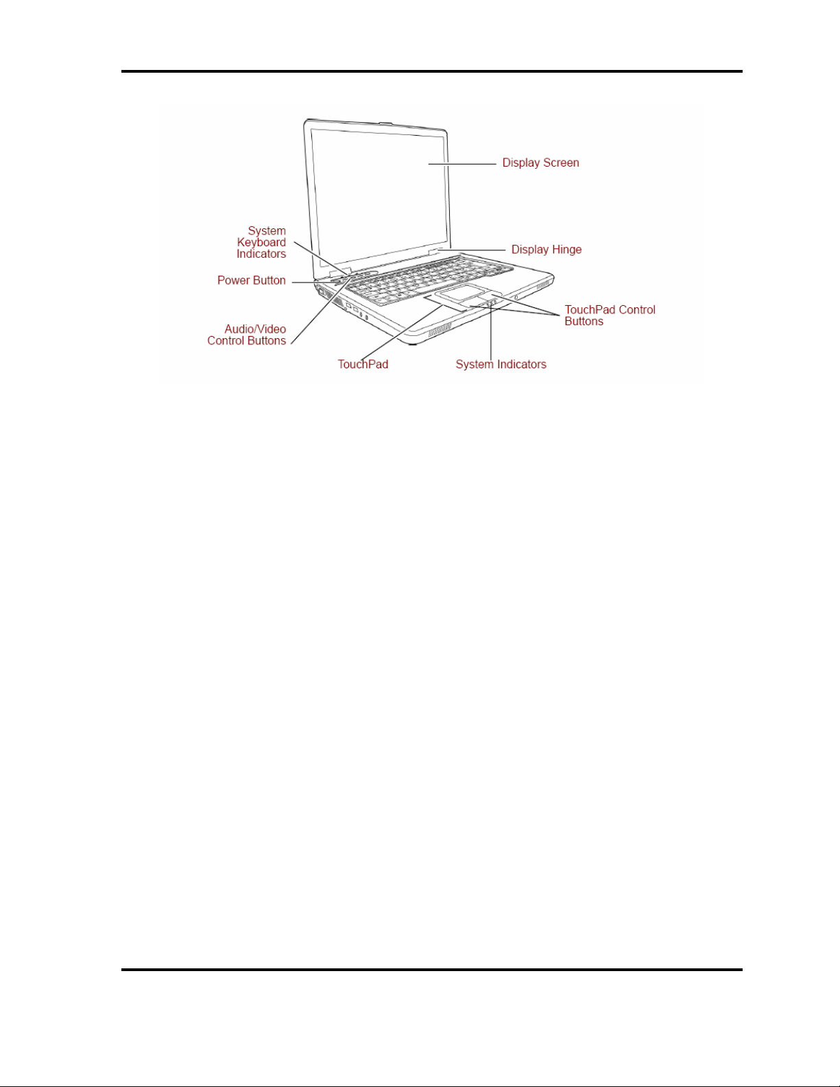
Figure 1-1 Front of the computer and the system units configuration ................................5
Figure 1-2 System block diagram........................................................................................6
Figure 1-3 2.5-inch HDD...................................................................................................11
Figure 1-4 DVD-ROM & CD-R/RW drive.......................................................................15
Figure 1-5 DVD Super Muti drive.....................................................................................20
Figure 1-6 Keyboard..........................................................................................................26
Figure 1-7 LCD module.....................................................................................................27
Tables
Table 1-1 2.5-inch HDD dimensions ...............................................................................11
Table 1-2 2.5-inch HDD specifications............................................................................13
Table 1-3 DVD-ROM & CD-R/RW drive outline dimensions........................................15
Table 1-4 DVD-ROM & CD-R/RW drive specifications................................................16
Table 1-5 DVD Super Multi drive outline dimensions....................................................20
Table 1-6 DVD Super Multi drive specifications ............................................................21
Table 1-7 LCD module specifications..............................................................................27
Table 1-8 FL inverter board specifications ......................................................................29
Table 1-9 Power supply output rating..............................................................................30
Table 1-10 Battery specifications.......................................................................................32
Table 1-11 Time required for charges of main battery ......................................................33
Table 1-12 Data preservation time.....................................................................................33
Table 1-13 Time required for charges of RTC battery.......................................................34
Table 1-14 AC adapter specifications................................................................................35
1-iv Satellite L20 Maintenance Ma nu al ( 96 0 -Q 01)

Chapter 1 Hardware Overview
Features
1.1 Features
The Satellite L20 (ATI Platform ) series are 2 spindle PCs running a Intel
Celeron®-M processor.
The features are listed below.
θ Microprocessor
Microprocessor that is used will be different of the model.
it supports Celeron-M as follows
Intel ® Celeron ®-M 350 (1.30GHz)
360 (1.40GHz)
370 (1.50GHz)
380 (1.60GHz)
L1 cache : 64KB (32KB + 32KB)
L2 cache : 1MB
®
Front side Bus : 400MHz
θ Memory
Two DDRII 533 SO-DIMM slots. Memory modules can be installed to provide a
maximum of 2GB. Memory modules are available in 256MB, 512MB and 1GB sizes.
For ATI RC410MB/SB400 Platform , DDRII 533 Module ran at DDRII 400.
θ VRAM
Shared with System RAM.
θ HDD
40GB, 60GB , 80GB and 100GB internal drives. 2.5 inch x 9.5mm height.
θ USB FDD (Option)
Satellite L20 Maintenance Manual(960-Q01)
1

Chatper 1 Hardware Overview
USB FDD supports 720KB and 1.44MB.
2 Satellite L20 Maintenance Manual (960-Q01)

Chapter 1 Hardware Overview
θ Display
LCD
Built-in 15.0-inch, XGA (1024 x 768 dots), 262,144 colors, amorphous silicon
TFT color display.
CRT
Supported via a RGB connector.
TV-out
S-VIDEO OUT port supported.
θ Keyboard
An-easy-to-use 84(US)/85(Euro)-key keyboard provides a numeric keypad overlay
for fast numeric data entry . The keyboard also includes two keys that have special
functions in Microsoft® Windows® XP. It supports software that uses a 101- or 102key enhanced keyboard.
θ PC card slot
The PC card slot (PCMCIA) accommodates one 5mm Type II card. The slot support
16-bit PC cards and Card Bus PC cards. CardBus supports 32-bit PC cards.
Satellite L20 Maintenance Manual(960-Q01)
3

Chatper 1 Hardware Overview
θ Optical devices
A DVD-ROM & CD-R/RW drive or DVD Super Multi drive is equipped.
θ Battery
The RTC battery is equipped inside the computer.
The main battery is a detachable lithium ion battery (4,300mAh:Li-Ion, 8cell).
θ USB (Universal Serial Bus)
Three USB ports are provided. The ports comply with the USB2.0 standard, which
enables data transfer speeds 40 times faster than USB1.1 standard. USB1.1 is also
supported.
θ Sound system
An internal stereo speaker, external monaural microphone connector, stereo
headphone connector is also equipped.
θ Wireless LAN (Mini PCI slot) (BTO)
The wireless LAN is equipped on the mini PCI slot.
θ LAN/MODEM
Connectors for LAN and Modem are separately mounted.
4 Satellite L20 Maintenance Manual (960-Q01)
Chapter 1 Hardware Overview
Figure 1-1 (ATI Platform ))Front of the computer and the system units configuration
Satellite L20 Maintenance Manual(960-Q01)
5
Chatper 1 Hardware Overview
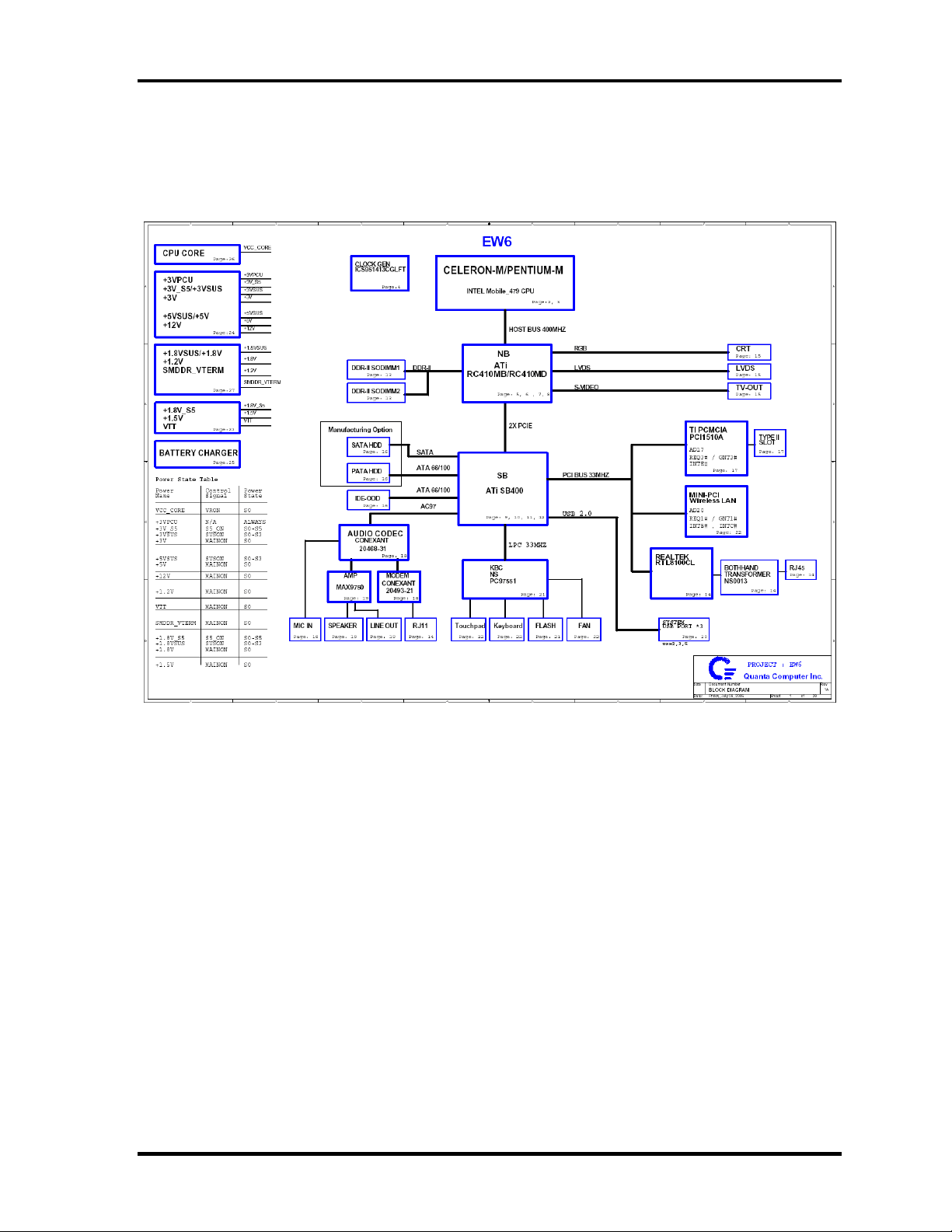
1.2 System Block Diagram
Figure 1-2 a/b shows the system block diagram.
Figure 1-2 System block diagram for ATI 410MB Platform
6 Satellite L20 Maintenance Manual (960-Q01)

Chapter 1 Hardware Overview
The PC contains the following components.
θ CPU
θ it supports Celeron-M CPU as follows
Intel ® Celeron ®-M 350 (1.30GHz)
360 (1.40GHz)
370 (1.50GHz)
380 (1.6GHz)
L1 cache : 64KB (32KB + 32KB)
L2 cache : 1MB
FSB : 400MHz Core voltage : 1.26V
θ Memory
Two memory slots capable of accepting DDRII-SDRAM 256MB, 512MB or 1GB
memory modules for a maximum of 2GB.
• 200-pin SO-DIMM
• 1.8V operation
• PC4200 support
θ BIOS ROM (Flash memory)
• 4Mbit (512K×8-bit chip)
θ Chipset
This gate array has the following elements and functions.
• North Bridge ATI RC410MB for Celeron-M Platform
− Celeron-M processor System Bus support
− DRAM Controller : DDRII 400/533 support
− A-Link Express Interface
− 707-ball 31mmx31mm FC-BGA Package
Satellite L20 Maintenance Manual(960-Q01)
7

Chatper 1 Hardware Overview
• South Bridge
− ATI SB400 for Celeron-M Platform
− PCI slot
− IDE controller
− SATA controller
− DMA controller
− USB host interface
− USB 2.0 host controller
− Interrupt controller
− SM Bus interface
− ACPI Power management
− Low Pin count (LPC) interface
− Real time clock
− AC’97 Rev. 2.3 interface
− 564-pin 31mmx31mm BGA Package
θ PC card controller (PCI1510, Texas Instrument-made)
− PCI Interface (PCI Rev. 2.3)
− PC Card Controller
8 Satellite L20 Maintenance Manual (960-Q01)

Chapter 1 Hardware Overview
θ VGA controller
• Intel VGA
− VRAM 32MB/64MB
− LVDS
− Or ATI
− VRAM 32MB/64MB/128MB
− LVDS
θ Other main system chips
• Clock Generator (ICS made ICS ) for ATI Platform
• EC/KBC (NS97551 x 1)
• AC97-CODEC (Conexant 20468-51 x1)
• Audio AMP (Maxim 9750x1)
•
θ Mini PCI
Wireless LAN card (BTO)
2.4GHz DSSS/OFDM LAN card is equipped. Conformity with IEEE 802.11b/g .
Transfer speed is maximum of 54Mbit/sec. Supports 128bit WEP.
θ LAN (Realtek RT8100CL x 1)
Controls LAN.
Supports 100Base-TX and 10Base-T.
Satellite L20 Maintenance Manual(960-Q01)
9

Chatper 1 Hardware Overview
θ MODEM (Conexant 20493-21x 1)
Supported by on board Modem + DAA daughter card.
Data and FAX transmission is available.
Supports ITU-TV.90.
The transfer speed of data receiving is 56kbps, of data sending is 33.6kbps and of
FAX is 14.4kbps. Actual speed depends on the quality of the line used.
Connected to telephone line through RJ11 MODEM jack.
10 Satellite L20 Maintenance Manual (960-Q01)
Chapter 1 Hardware Overview
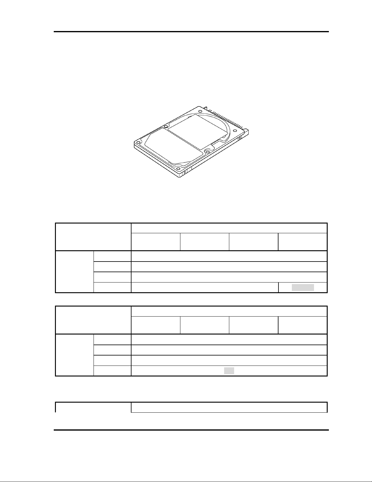
1.3 2.5-inch Hard Disk Drive
A compact, high-capacity HDD with a height of 9.5mm. Contains a 2.5-inch magnetic disk
and magnetic heads.
Figure 1-3 shows a view of the 2.5-inch HDD and Tables 1-1 and 1-2 list the specifications.
Figure 1-3 2.5-inch HDD
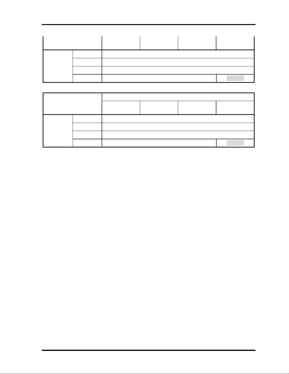
Table 1-1 2.5-inch HDD dimensions
Toshiba 40G 4200rpm PLUTO MK4025GAS
Outline
dimensions
Outline
dimensions
Parameter
Width (mm)
Height (mm)
Depth (mm)
Weight (g)
Parameter
Width (mm)
Height (mm)
Depth (mm)
Weight (g)
Parameter Standard value
Fujitsu
MHV2100AT
Fujitsu
MHV2100AH
Standard value
Fujitsu
MHV2080AT
Fujitsu
MHV2060AT
Fujitsu
MHV2040AT
70.0
9.5
100.0
100(max.) 96(max)
Standard value
Fujitsu
MHV2080AH
Fujitsu
MHV2060AH
70
9.5
100.0
101
Satellite L20 Maintenance Manual(960-Q01)
11
Chatper 1 Hardware Overview
Outline
dimensions
Outline
dimensions
Width (mm)
Height (mm)
Depth (mm)
Weight (g)
Parameter
Width (mm)
Height (mm)
Depth (mm)
Weight (g)
Toshiba
MK1031GAS
Toshiba
MK1032GAX
Toshiba
MK8025GAS
Toshiba
MK6025GAS
Toshiba
MK4025GAS
69.85
9.5
100.0
99 (max.) 95(max)
Standard value
Toshiba
MK8026GAX
Toshiba
MK6026GAX
Toshiba
MK4026GAX
70.0
9.5
100.0
101 (max.) 96(max)
12 Satellite L20 Maintenance Manual (960-Q01)
Chapter 1 Hardware Overview
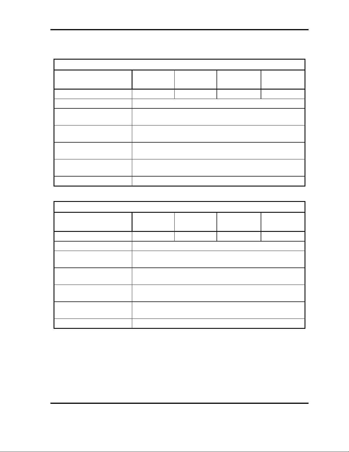
Table 1-2 2.5-inch HDD Specifications
Specification
Parameter
Storage size (formatted) 100GB 80GB 60GB 40GB
Speed (RPM) 4,200
Data transfer speed
(Mbits/s)
Interface transfer rate
(MB/s)
Average random seek time
(read) (ms)
Average random seek time
(write) (ms)
Power-on-to-ready (sec) 3.5 (typ.)
Fujitsu
MHV2100AT
Fujitsu
MHV2080AT
100 (Ultra DMA Mode)
MHV2060AT
350
12(typ.)
-
Fujitsu
Fujitsu
MHV2040AT
Specification
Parameter
Storage size (formatted) 100GB 80GB 60GB
Speed (RPM) 5,400
Fujitsu
MHV2100AH
Fujitsu
MHV2080AH
Fujitsu
MHV2060AH
Data transfer speed
(Mbits/s)
Interface transfer rate
(MB/s)
Average random seek time
(read) (ms)
Average random seek time
(write) (ms)
Power-on-to-ready (sec) 4
100 (Ultra DMA Mode)
Satellite L20 Maintenance Manual(960-Q01)
475
12
-
13
Chatper 1 Hardware Overview
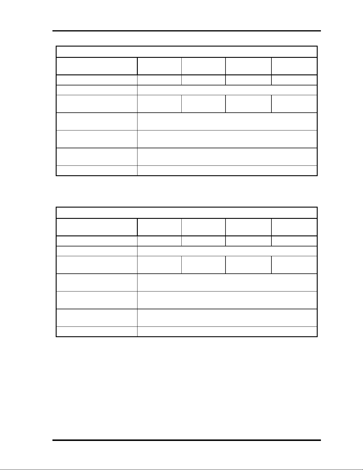
Specification
Parameter
Storage size (formatted) 100GB 80GB 60GB 40GB
Speed (RPM) 4,200
Data transfer speed
(Mbits/s)
Interface transfer rate
(MB/s)
Average random seek time
(read) (ms)
Average random seek time
(write) (ms)
Power-on-to-ready (sec) 4 (typical)/10 sec (Max)
Toshiba
MK1031GAS
170-373 175-342 202-308 175-342
Toshiba
MK8025GAS
100 (Ultra DMA Mode)
12
-
Toshiba
MK6025GAS
Toshiba
MK4025GAS
Specification
Parameter
Toshiba
MK1032GAX
Toshiba
MK8026GAX
Toshiba
MK6026GAX
Toshiba
MK4026GAX
Storage size (formatted) 100GB 80GB 60GB 40GB
Speed (RPM) 5,400
Data transfer speed
(Mbits/s)
Interface transfer rate
(MB/s)
Average random seek time
(read) (ms)
Average random seek time
(write) (ms)
Power-on-to-ready (sec) 4 (typical)/10 sec (Max)
235-445 233-446 258-394 233-446
100 (Ultra DMA Mode)
12
-
14 Satellite L20 Maintenance Manual (960-Q01)
 Loading...