

Toshiba Satellite A665 Series, Satellite A660D, Satellite A660 Series, Satellite P755 Series Maintenance Manual

Toshiba Personal Computer
Satellite & Satellite Pro
Maintenance Manual
TOSHIBA CORPORATION
[CONFIDENTIAL]

Copyright
© 2011 by Toshiba Corporation. All rights reserved. Under the copyright laws, this manual
cannot be reproduced in any form without the prior written permission of Toshiba. No patent
liability is assumed with respect to the use of the information contained herein.
Toshiba Personal Computer Satellite & Satellite Pro Maintenance Manual
First edition November. 2011
Disclaimer
The information presented in this manual has been reviewed and validated for accuracy. The
included set of instructions and descriptions are accurate for the Satellite Series at the time of this
manual's production. However, succeeding computers and manuals are subject to change without
notice. Therefore, Toshiba assumes no liability for damages incurred directly or indirectly from
errors, omissions, or discrepancies between any succeeding product and this manual.
Trademarks
IBM is a registered trademark, and OS/2 and PS/2 are trademarks of IBM Corporation.
Microsoft, MS-DOS, Windows, DirectSound and DirectMusic are registered trademarks of
Microsoft Corporation.
Intel and Pentium are registered trademarks, and Speed Step is a trademark of Intel Corporation.
Sound Blaster is a registered trademark of Creative Technology Ltd.
Getronics is a registered trademark of Getronics Data Computer Corporation.
Photo CD is a trademark of Eastman Kodak.
All other properties are trademarks or registered trademarks of their respective holders.
Satellite P750/P755 Maintenance Manual
DANGER: “Danger” indicates the existence of a hazard that could result in death or
serious bodily injury if the safety instruction is not observed.
WARNING: “Warning” indicates the existence of a hazard that could result in bodily
injury if the safety instruction is not observed.
CAUTION: “Caution” indicates the existence of a hazard that could result in property
damage if the safety instruction is not observed.
NOTE: “Note” contains general information that relates to your safe maintenance
service.
Preface
This maintenance manual describes how to perform hardware service maintenance for the Toshiba
Personal Computer Satellite, referred to as the Satellite Series in this manual.
The procedures described in this manual are intended to help service technicians isolate faulty
Field Replaceable Units (FRUs) and replace them in the field.
SAFETY PRECAUTIONS
Four types of messages are used in this manual to bring important information to your attention.
Each of these messages will be italicized and identified as shown below.
Improper repair of the computer may result in safety hazards. Toshiba requires service technicians
and authorized dealers or service providers to ensure the following safety precautions are adhered
to strictly.
Be sure to fasten screws securely with the right screwdriver. If a screw is not fully fastened, it
could come loose, creating a danger of a short circuit, which could cause overheating,
smoke or fire.
If you replace the battery pack or RTC battery, be sure to use only the same model battery or
an equivalent battery recommended by Toshiba. Installation of the wrong battery can cause
the battery to explode.
Satellite P750/P755 Maintenance Manual iii

The manual is divided into the following parts:
Chapter 1 Hardware Overview describes the Satellite Series system unit and each
FRU.
Chapter 2 Troubleshooting Procedures explains how to diagnose and resolve FRU
problems.
Chapter 3 Test and Diagnostics describes how to perform test and diagnostic
operations for maintenance service.
Chapter 4 Replacement Procedures describes the removal and replacement of the
FRUs.
Appendices The appendices describe the following:
Handling the LCD module
Board layout
Pin assignments
Keyboard scan/character codes
Key layout
Screw torque list
Reliability
Conventions
This manual uses the following formats to describe, identify, and highlight terms and operating
procedures.
Acronyms
On the first appearance and whenever necessary for clarification, acronyms are enclosed in
parentheses following their definition. For example:
Read Only Memory (ROM)
Keys
Keys are used in the text to describe many operations. The key top symbol as it appears on the
keyboard is printed in boldface type.
Key operation
Satellite P750/P755 Maintenance Manual

Some operations require you to simultaneously use two or more keys. We identify such operations
by the key top symbols separated by a plus (+) sign. For example, Ctrl + Pause (Break) means
you must hold down Ctrl and at the same time press Pause (Break). If three keys are used, hold
down the first two and at the same time press the third.
User input
Text that you are instructed to type in is shown in the boldface type below:
DISKCOPY A: B:
The display
Text generated by the computer that appears on its display is presented in the typeface below:
Format complete
System transferred
Satellite P750/P755 Maintenance Manual v

Table of Contents
Chapter 1 Hardware Overview
1.1 Features ....................................................................... Fehler! Textmarke nicht definiert.
1.2 2.5-inch HDD .............................................................. Fehler! Textmarke nicht definiert.
1.3 DVD Super Multi (+-R Double Layer) ....................... Fehler! Textmarke nicht definiert.
1.4 BD-RE and BD-Combo drives ................................... Fehler! Textmarke nicht definiert.
1.5 Power Supply .............................................................. Fehler! Textmarke nicht definiert.
1.6 Batteries ...................................................................... Fehler! Textmarke nicht definiert.
1.6.1 Main Battery ................................................. Fehler! Textmarke nicht definiert.
1.6.2 Battery Charging Control ............................. Fehler! Textmarke nicht definiert.
1.6.3 RTC Battery ................................................. Fehler! Textmarke nicht definiert.
Figures
Figure 1-1A ID Parts Description Placement Part A ..... Fehler! Textmarke nicht definiert.
Figure 1-2 SATA HDD .............................................. Fehler! Textmarke nicht definiert.
Figure 1-3 DVD Super Multi Drive ........................... Fehler! Textmarke nicht definiert.
Figure 1-4 BD-RE or BD-Combo drive (depending on the model)Fehler! Textmarke nicht
definiert.
Tables
Table 1-1 HDD Specifications .................................. Fehler! Textmarke nicht definiert.
Table 1-2 DVD Super Multi Drive Specifications .... Fehler! Textmarke nicht definiert.
Table 1-3 Blu-ray Disc Drive specifications ............. Fehler! Textmarke nicht definiert.
Table 1-4 Quick/Normal Charging Time .................. Fehler! Textmarke nicht definiert.
Satellite P750/P755 Maintenance Manual

Chapter 2 Troubleshooting Procedures
2.1 Troubleshooting Introduction ...................................................................................... 3
2.2 Troubleshooting Flowchart ……………………………………………………………4
2.3 Power Supply Troubleshooting ……………………………………………………….9
2.4 Display Troubleshooting ..............................................................................................14
2.5 Keyboard Troubleshooting.......................................................................................... 17
2.6 External USB Devices Troubleshooting ......................................................................19
2.7 TV-tuner Troubleshooting ...........................................................................................21
2.8 TouchPad Troubleshooting ..........................................................................................22
2.9 Speaker Troubleshooting .............................................................................................25
2.10 Optical drive troubleshooting ......................................................................................27
2.11 Wireless LAN Troubleshooting ........................................................................................ 30
2.12 Camera Troubleshooting…………………………………………… ……………….32
2.13 Bluetooth Troubleshooting…………………...…………………………….……….. 34
2.14 Bridge Media slot Troubleshooting……………………………………………..……36
2.15 HDD/SSD Troubleshooting……………………………………………..……………38
2.16 CRT failure Troubleshooting ……………………………………………………….. 40
2.17 HDMI CEC Troubleshooting ………………………………………………………...42
2.18 MIC Troubleshooting ………………………………………………………………. 44
2.19 Finger print Troubleshooting ……………………………………………………….46
2.20 USB Troubleshooting …………………………………...………………………….48
2.21 Felica Troubleshooting ………………………….………………………………….. 50
2.22 3D sensor troubleshooting process …………………………………………………..52
2.23 Sleep & charge Troubleshooting……………………………………………………..54
2.24 CIR Troubleshooting…………………………………………………………………56
2.25 Sleep & Play music Troubleshooting……………………………………………...…58
2.26 Wimax Troubleshooting ..............................................................................................60
2.27 LAN Troubleshooting………………………………………………...………………62
2.28 3G Troubleshooting…………………………………………………………………..64
2.29 JET Troubleshooting……………………………………………………………...…..67
2.30 Ambient Light sensor Troubleshooting ……………….…………...………………69
2.31 Battery Troubleshooting………………………………………………..………...…..71
2.32 LED Troubleshooting ……………….……………………...……...………………73
Satellite P750/P755 Maintenance Manual vii

Figures
Figure 2-1 Troubleshooting flowchart (2/1) ………………………………………………5
Figure 2-1 Troubleshooting flowchart (2/2) ………………………………………………6
Figure2-2 Power Supply Troubleshooting Process …………………………………..…..9
Figure 2-3 Display troubleshooting process ……………………………………………..14
Figure 2-4 Keyboard troubleshooting process ................................................................... 17
Figure 2-5 External USB device troubleshooting process ................................................. 19
Figure 2-6 TV-tuner troubleshooting process .................................................................... 21
Figure 2-7 TouchPad troubleshooting process .................................................................. 23
Figure 2-8 Speaker troubleshooting process ...................................................................... 25
Figure 2-9 Optical drive troubleshooting process ............................................................. 27
Figure 2-10 Wireless LAN troubleshooting process…………………………………...…20
Figure 2-11 Camera Troubleshooting process…………………………………………….32
Figure 2-12 Bluetooth troubleshooting process ....……………………………….……….34
Figure 2-13 5 in 1 card troubleshooting process……………………………..…….………36
Figure 2-14 HDD troubleshooting process……………………………….………………..38
Figure 2-15 CRT failure troubleshooting process ………………………………………...40
Figure 2-16 HDMI CEC troubleshooting process ………………………………………...42
Figure 2-17 MIC troubleshooting process ………………………………………………...44
Figure 2-18 Finger printer troubleshooting process ………………………………………46
Figure 2-19 USB3.0 Troubleshooting process………………………….………………....48
Figure 2-20 Felica Troubleshooting process..……………….………….………………... 50
Figure 2-21 3D sensor troubleshooting process ………………..…………………………52
Figure 2-22 Sleep & Charge Troubleshooting…………….………….……….…..…...….54
Figure 2-23 CIR troubleshooting process …………….………...…………………………56
Figure 2-24 Sleep and Play music troubleshooting process ………………………………58
Figure 2-25 Wimax Troubleshooting process.…………….………….……….…..…...….60
Figure 2-26 LAN troubleshooting process …………………….…………………………..62
Figure 2-27 3G troubleshooting process …………….………...…………………..………64
Figure 2-28 JET Troubleshooting process………………….………….……….…..…...…67
Figure 2-29 Ambient Light Sensor troubleshooting process………………………….........69
Figure 2-30 Battery troubleshooting process………………….………….………...…....…71
Figure 2-31 LED troubleshooting process…………………………………………….........73
Satellite P750/P755 Maintenance Manual

Tables
Table 2-1 Battery LED ................................................. Fehler! Textmarke nicht definiert.
Table 2-2 DC-IN LED .................................................. Fehler! Textmarke nicht definiert.
Chapter 3 Tests and Diagnostics
3.1 The Diagnostic Test ............................................................................................................... 2
3.2 Executing the Diagnostic Test ............................................................................................... 3
3.3 Display Configuration ........................................................................................................... 6
3.4 Audio sound Test ................................................................................................................... 7
3.5 Fan ON/OFF Test................................................................................................................. 10
3.6 Main Battery Charge Test .................................................................................................... 13
3.7 FDD Test .............................................................................................................................. 14
3.8 Memory Check ..................................................................................................................... 15
3.9 Keyboard Test ...................................................................................................................... 18
3.10 Mouse (Pad) Test ................................................................................................................. 20
3.11 LCD Pixels Mode Test ......................................................................................................... 21
3.12 Magnetic switch Test ........................................................................................................... 22
3.13 LAN Test.............................................................................................................................. 24
3.14 RTC Test .............................................................................................................................. 26
3.15 BUTTON Test……..…………...……….…….…………………………...……..............27
3.16 1st HDDTest …………………………....…………….…….………....….…….…..........29
3.17 RDMI Test………………...……………………….……….……………..…………........31
3.18 WDMI Test …………….………………………….……………...…....…..………….....32
3.19 G Sensor Test ……………………………………………………..……….…………........34
3.20 TP TYPE R/W Test………………………………………………………….…….…..…...38
3.21 EEPROM Setting ………………………..………………………...……….………..…...41
3.22 TOSHIBA LOGO Setting………………………………………...…………………...…...45
3.23 DYNABOOK LOGOSetting..............................................................................................47
3.24 LEDTest............................................................................................................................49
Satellite P750/P755 Maintenance Manual ix

Chapter 4 Replacement Procedures (UMA)
4.1 General ........................................................................ Fehler! Textmarke nicht definiert.
Safety Precautions ....................................................... Fehler! Textmarke nicht definiert.
Before You Begin ........................................................ Fehler! Textmarke nicht definiert.
Disassembly Procedures .............................................. Fehler! Textmarke nicht definiert.
Assembly Procedures .................................................. Fehler! Textmarke nicht definiert.
Tools and Equipment .................................................. Fehler! Textmarke nicht definiert.
Screw Tightening Torque ............................................ Fehler! Textmarke nicht definiert.
Colors of Screw Shanks .............................................. Fehler! Textmarke nicht definiert.
Symbols of Screws on the Laptop Body ..................... Fehler! Textmarke nicht definiert.
Symbol examples ........................................................ Fehler! Textmarke nicht definiert.
4.2 Battery ......................................................................... Fehler! Textmarke nicht definiert.
Removing the Battery Pack ......................................... Fehler! Textmarke nicht definiert.
Installing the Battery Pack........................................... Fehler! Textmarke nicht definiert.
4.3 HDD ............................................................................ Fehler! Textmarke nicht definiert.
Removing the HDD ..................................................... Fehler! Textmarke nicht definiert.
Installing the HDD ...................................................... Fehler! Textmarke nicht definiert.
4.4 Memory ....................................................................... Fehler! Textmarke nicht definiert.
Removing the Optional Memory ................................. Fehler! Textmarke nicht definiert.
Installing the Optional Memory .................................. Fehler! Textmarke nicht definiert.
4.5 Keyboard ..................................................................... Fehler! Textmarke nicht definiert.
Removing the Keyboard .............................................. Fehler! Textmarke nicht definiert.
Installing the Keyboard ............................................... Fehler! Textmarke nicht definiert.
4.6 WLAN Card ................................................................ Fehler! Textmarke nicht definiert.
Removing the WLAN Card ......................................... Fehler! Textmarke nicht definiert.
Installing the WLAN Card .......................................... Fehler! Textmarke nicht definiert.
4.7 ODD Module (Tray-load) ........................................... Fehler! Textmarke nicht definiert.
Removing the ODD Module (Tray-load) .................... Fehler! Textmarke nicht definiert.
Installing the ODD Module (Tray-load) ...................... Fehler! Textmarke nicht definiert.
Satellite P750/P755 Maintenance Manual

Disassembling the ODD (Tray-load) ........................... Fehler! Textmarke nicht definiert.
Assembling the ODD (Tray-load) ............................... Fehler! Textmarke nicht definiert.
4.8 Logic Upper Assembly ............................................... Fehler! Textmarke nicht definiert.
Removing the Logic Upper Assembly ........................ Fehler! Textmarke nicht definiert.
Installing the Logic Upper Assembly .......................... Fehler! Textmarke nicht definiert.
4.9 ODD Module (Slot-load) ............................................ Fehler! Textmarke nicht definiert.
Removing the ODD Module (Slot-load) ..................... Fehler! Textmarke nicht definiert.
Installing the ODD Module (Slot-load) ....................... Fehler! Textmarke nicht definiert.
Disassembling the ODD (Slot-load) ........................... Fehler! Textmarke nicht definiert.
Assembling the ODD (Slot-load) ................................ Fehler! Textmarke nicht definiert.
4.10 FeliCa Card ................................................................. Fehler! Textmarke nicht definiert.
Removing the FeliCa Card .......................................... Fehler! Textmarke nicht definiert.
Installing the FeliCa Card ............................................ Fehler! Textmarke nicht definiert.
4.11 Fingerprint Scanner Bracket ....................................... Fehler! Textmarke nicht definiert.
Removing the Fingerprint Scanner Bracket ................ Fehler! Textmarke nicht definiert.
Installing the Fingerprint Scanner Bracket .................. Fehler! Textmarke nicht definiert.
4.12 Touch Pad Board ......................................................... Fehler! Textmarke nicht definiert.
Removing the Touch Pad Board ................................. Fehler! Textmarke nicht definiert.
Installing the Touch Pad Board ................................... Fehler! Textmarke nicht definiert.
4.13 Speakers and Speaker Cushions .................................. Fehler! Textmarke nicht definiert.
Removing the Speakers ............................................... Fehler! Textmarke nicht definiert.
Removing the Speaker Cushions ................................. Fehler! Textmarke nicht definiert.
Installing the Speaker Cushions .................................. Fehler! Textmarke nicht definiert.
Installing the Speakers ................................................. Fehler! Textmarke nicht definiert.
4.14 USB Board .................................................................. Fehler! Textmarke nicht definiert.
Removing the USB Board ........................................... Fehler! Textmarke nicht definiert.
Installing the USB Board ............................................ Fehler! Textmarke nicht definiert.
4.15 Indicator Board ........................................................... Fehler! Textmarke nicht definiert.
Removing the Indicator Board .................................... Fehler! Textmarke nicht definiert.
Installing the Indicator Board ...................................... Fehler! Textmarke nicht definiert.
4.16 Thermal Fan ................................................................ Fehler! Textmarke nicht definiert.
Satellite P750/P755 Maintenance Manual xi

Removing the Thermal Fan ......................................... Fehler! Textmarke nicht definiert.
Installing the Thermal Fan .......................................... Fehler! Textmarke nicht definiert.
4.17 Motherboard Assembly ............................................... Fehler! Textmarke nicht definiert.
Removing the Motherboard Assembly........................ Fehler! Textmarke nicht definiert.
Installing the Motherboard .......................................... Fehler! Textmarke nicht definiert.
4.18 Thermal Module ......................................................... Fehler! Textmarke nicht definiert.
Removing the Thermal Module .................................. Fehler! Textmarke nicht definiert.
Installing the Thermal Module .................................... Fehler! Textmarke nicht definiert.
4.19 CPU ............................................................................. Fehler! Textmarke nicht definiert.
Removing the CPU ..................................................... Fehler! Textmarke nicht definiert.
Installing the CPU ....................................................... Fehler! Textmarke nicht definiert.
4.20 Power Membrane ........................................................ Fehler! Textmarke nicht definiert.
Removing the Power Membrane ................................. Fehler! Textmarke nicht definiert.
Installing the Power Membrane .................................. Fehler! Textmarke nicht definiert.
4.21 Display Assembly ....................................................... Fehler! Textmarke nicht definiert.
Removing the Display Assembly ................................ Fehler! Textmarke nicht definiert.
Installing the Display Assembly .................................. Fehler! Textmarke nicht definiert.
4.22 LCD Bezel .................................................................. Fehler! Textmarke nicht definiert.
Removing the LCD Bezel ........................................... Fehler! Textmarke nicht definiert.
Installing the LCD Bezel ............................................. Fehler! Textmarke nicht definiert.
4.23 DC/DC Board ............................................................. Fehler! Textmarke nicht definiert.
Removing the DC/DC Board ...................................... Fehler! Textmarke nicht definiert.
Installing the DC/DC Board ........................................ Fehler! Textmarke nicht definiert.
4.24 LCD Panel ................................................................... Fehler! Textmarke nicht definiert.
Removing the LCD Panel ........................................... Fehler! Textmarke nicht definiert.
Installing the LCD Panel ............................................. Fehler! Textmarke nicht definiert.
4.25 LCD Panel Hinges ...................................................... Fehler! Textmarke nicht definiert.
Removing the LCD Panel Hinges ............................... Fehler! Textmarke nicht definiert.
Installing the LCD Panel Hinges ................................. Fehler! Textmarke nicht definiert.
4.26 Web Camera ............................................................... Fehler! Textmarke nicht definiert.
Removing the Web Camera ........................................ Fehler! Textmarke nicht definiert.
Satellite P750/P755 Maintenance Manual

Installing the Web Camera .......................................... Fehler! Textmarke nicht definiert.
4.27 WLAN Antennas......................................................... Fehler! Textmarke nicht definiert.
Removing the WLAN Antennas ................................. Fehler! Textmarke nicht definiert.
Installing the WLAN Antennas ................................... Fehler! Textmarke nicht definiert.
4.28 LVDS Cable ................................................................ Fehler! Textmarke nicht definiert.
Removing the LVDS Cable ......................................... Fehler! Textmarke nicht definiert.
Installing the LVDS Cable .......................................... Fehler! Textmarke nicht definiert.
Figures
Figure 4.1 Removing the Battery Pack ............................. Fehler! Textmarke nicht definiert.
Figure 4.2 Removing the HDD door ................................. Fehler! Textmarke nicht definiert.
Figure 4.3 Releasing the HDD from the connector ........... Fehler! Textmarke nicht definiert.
Figure 4.4 Removing the HDD from the HDD bay .......... Fehler! Textmarke nicht definiert.
Figure 4.5 Removing the HDD foil .................................. Fehler! Textmarke nicht definiert.
Figure 4.6 Securing the HDD foil ..................................... Fehler! Textmarke nicht definiert.
Figure 4.7 Removing the RAM door ................................ Fehler! Textmarke nicht definiert.
Figure 4.8 Removing the RAM from the connectors ........ Fehler! Textmarke nicht definiert.
Figure 4.9 Removing the three screws securing the keyboardFehler! Textmarke nicht definiert.
Figure 4.10 Releasing the keyboard .................................. Fehler! Textmarke nicht definiert.
Figure 4.11 Disconnecting the cable and removing the keyboard ..... Fehler! Textmarke nicht
definiert.
Figure 4.12 Removing the WLAN Card ........................... Fehler! Textmarke nicht definiert.
Figure 4.13 Removing the ODD module (Tray-load) ....... Fehler! Textmarke nicht definiert.
Figure 4.14 Removing the ODD bracket from the ODD .. Fehler! Textmarke nicht definiert.
Figure 4.15 Hooks on the inside of the Tray-load ODD bezelFehler! Textmarke nicht definiert.
Figure 4.16 Removing thirteen screws from the bottom of the laptopFehler! Textmarke nicht
definiert.
Figure 4.17 Disconnecting the cables and removing two upper logic assembly screws . Fehler!
Textmarke nicht definiert.
Figure 4.18 Removing the logic upper assembly .............. Fehler! Textmarke nicht definiert.
Figure 4.19 Disassembling the Slot-load ODD ................ Fehler! Textmarke nicht definiert.
Satellite P750/P755 Maintenance Manual xiii

Figure 4.20 Removing the FeliCa card from the logic upper assemblyFehler! Textmarke nicht
definiert.
Figure 4.21 Raising the fingerprint scanner bracket from the logic upper assembly ...... Fehler!
Textmarke nicht definiert.
Figure 4.22 Working the fingerprint scanner bracket looseFehler! Textmarke nicht definiert.
Figure 4.23 Removing the fingerprint scanner bracket from the logic upper assembly . Fehler!
Textmarke nicht definiert.
Figure 4.24 Removing the touch pad board ...................... Fehler! Textmarke nicht definiert.
Figure 4.25 Removing the speakers .................................. Fehler! Textmarke nicht definiert.
Figure 4.26 Removing the speaker cushions .................... Fehler! Textmarke nicht definiert.
Figure 4.27 Removing the USB board .............................. Fehler! Textmarke nicht definiert.
Figure 4.28 Removing the indicator board ....................... Fehler! Textmarke nicht definiert.
Figure 4.29 Removing the thermal fan ............................. Fehler! Textmarke nicht definiert.
Figure 4.30 Removing the DC in cable from the connector slot ....... Fehler! Textmarke nicht
definiert.
Figure 4.31 Removing the screw and disconnect four cablesFehler! Textmarke nicht definiert.
Figure 4.32 Removing the discreet motherboard from the system .... Fehler! Textmarke nicht
definiert.
Figure 4.33 Removing the thermal module ...................... Fehler! Textmarke nicht definiert.
Figure 4.34 Reapplying Shinetsu 7762 grease on the thermal module and remove any release
papers ........................................................ Fehler! Textmarke nicht definiert.
Figure 4.35 Installing the thermal module ........................ Fehler! Textmarke nicht definiert.
Figure 4.36 Removing the CPU ........................................ Fehler! Textmarke nicht definiert.
Figure 4.37 Removing the power membrane .................... Fehler! Textmarke nicht definiert.
Figure 4.38 Removing the display assembly .................... Fehler! Textmarke nicht definiert.
Figure 4.39 Removing four screws securing the LCD bezel to the display assembly .... Fehler!
Textmarke nicht definiert.
Figure 4.40 Prying up the LCD bezel from the outside edgesFehler! Textmarke nicht definiert.
Figure 4.41 Releasing the DC/DC board from the snaps .. Fehler! Textmarke nicht definiert.
Figure 4.42 Removing the DC/DC board the display assemblyFehler! Textmarke nicht definiert.
Figure 4.43 Removing the four screws securing the LCD panel ....... Fehler! Textmarke nicht
definiert.
Figure 4.44 Disconnecting the camera cable .................... Fehler! Textmarke nicht definiert.
Figure 4.45 Disconnecting the LVDS cable ..................... Fehler! Textmarke nicht definiert.
Satellite P750/P755 Maintenance Manual

Figure 4.46 Removing the LCD panel hinges from the LCD Panel .. Fehler! Textmarke nicht
definiert.
Figure 4.47 Removing the web camera from the display assembly ... Fehler! Textmarke nicht
definiert.
Figure 4.48 Removing the WLAN antennas from the display assemblyFehler! Textmarke nicht
definiert.
Figure 4.49 Removing the LVDS cable from the LCD panelFehler! Textmarke nicht definiert.
Chapter 4 Replacement Procedures (Discrete)
4.1 General ........................................................................ Fehler! Textmarke nicht definiert.
Safety Precautions ....................................................... Fehler! Textmarke nicht definiert.
Before You Begin ........................................................ Fehler! Textmarke nicht definiert.
Disassembly Procedures .............................................. Fehler! Textmarke nicht definiert.
Assembly Procedures .................................................. Fehler! Textmarke nicht definiert.
Tools and Equipment .................................................. Fehler! Textmarke nicht definiert.
Screw Tightening Torque ............................................ Fehler! Textmarke nicht definiert.
Colors of Screw Shanks .............................................. Fehler! Textmarke nicht definiert.
Symbols of Screws on the Laptop Body ..................... Fehler! Textmarke nicht definiert.
Symbol examples ........................................................ Fehler! Textmarke nicht definiert.
4.2 Battery ......................................................................... Fehler! Textmarke nicht definiert.
Removing the Battery Pack ......................................... Fehler! Textmarke nicht definiert.
Installing the Battery Pack ........................................... Fehler! Textmarke nicht definiert.
4.3 HDD ............................................................................ Fehler! Textmarke nicht definiert.
Removing the HDD ..................................................... Fehler! Textmarke nicht definiert.
Installing the HDD ...................................................... Fehler! Textmarke nicht definiert.
4.4 Memory ....................................................................... Fehler! Textmarke nicht definiert.
Removing the Optional Memory ................................. Fehler! Textmarke nicht definiert.
Installing the Optional Memory .................................. Fehler! Textmarke nicht definiert.
4.5 Keyboard ..................................................................... Fehler! Textmarke nicht definiert.
Removing the Keyboard .............................................. Fehler! Textmarke nicht definiert.
Installing the Keyboard ............................................... Fehler! Textmarke nicht definiert.
Satellite P750/P755 Maintenance Manual xv

4.6 TV Tuner Card and WLAN Card ............................... Fehler! Textmarke nicht definiert.
Removing the WLAN Card ......................................... Fehler! Textmarke nicht definiert.
Removing the TV Tuner Card ..................................... Fehler! Textmarke nicht definiert.
Installing the WLAN Card .......................................... Fehler! Textmarke nicht definiert.
Installing the TV Tuner Card ...................................... Fehler! Textmarke nicht definiert.
4.7 ODD Module (Tray-load) ........................................... Fehler! Textmarke nicht definiert.
Removing the ODD Module (Tray-load) .................... Fehler! Textmarke nicht definiert.
Installing the ODD Module (Tray-load) ...................... Fehler! Textmarke nicht definiert.
Disassembling the ODD (Tray-load) .......................... Fehler! Textmarke nicht definiert.
Assembling the ODD (Tray-load) ............................... Fehler! Textmarke nicht definiert.
4.8 Logic Upper Assembly ............................................... Fehler! Textmarke nicht definiert.
Removing the Logic Upper Assembly ........................ Fehler! Textmarke nicht definiert.
Installing the Logic Upper Assembly .......................... Fehler! Textmarke nicht definiert.
4.9 ODD Module (Slot-load) ............................................ Fehler! Textmarke nicht definiert.
Removing the ODD Module (Slot-load) ..................... Fehler! Textmarke nicht definiert.
Installing the ODD Module (Slot-load) ...................... Fehler! Textmarke nicht definiert.
Disassembling the ODD (Slot-load) ........................... Fehler! Textmarke nicht definiert.
Assembling the ODD (Slot-load) ................................ Fehler! Textmarke nicht definiert.
4.10 FeliCa Card ................................................................. Fehler! Textmarke nicht definiert.
Removing the FeliCa Card .......................................... Fehler! Textmarke nicht definiert.
Installing the FeliCa Card ........................................... Fehler! Textmarke nicht definiert.
4.11 Fingerprint Scanner Bracket ....................................... Fehler! Textmarke nicht definiert.
Removing the Fingerprint Scanner Bracket ................ Fehler! Textmarke nicht definiert.
Installing the Fingerprint Scanner Bracket .................. Fehler! Textmarke nicht definiert.
4.12 Touch Pad Board......................................................... Fehler! Textmarke nicht definiert.
Removing the Touch Pad Board ................................. Fehler! Textmarke nicht definiert.
Installing the Touch Pad Board ................................... Fehler! Textmarke nicht definiert.
4.13 Speakers and Speaker Cushions.................................. Fehler! Textmarke nicht definiert.
Removing the Speakers ............................................... Fehler! Textmarke nicht definiert.
Removing the Speaker Cushions ................................ Fehler! Textmarke nicht definiert.
Installing the Speaker Cushions .................................. Fehler! Textmarke nicht definiert.
Satellite P750/P755 Maintenance Manual

Installing the Speakers ................................................. Fehler! Textmarke nicht definiert.
4.14 USB Board .................................................................. Fehler! Textmarke nicht definiert.
Removing the USB Board ........................................... Fehler! Textmarke nicht definiert.
Installing the USB Board ............................................ Fehler! Textmarke nicht definiert.
4.15 Indicator Board ........................................................... Fehler! Textmarke nicht definiert.
Removing the Indicator Board .................................... Fehler! Textmarke nicht definiert.
Installing the Indicator Board ...................................... Fehler! Textmarke nicht definiert.
4.16 Thermal Fan ................................................................ Fehler! Textmarke nicht definiert.
Removing the Thermal Fan ......................................... Fehler! Textmarke nicht definiert.
Installing the Thermal Fan .......................................... Fehler! Textmarke nicht definiert.
4.17 Motherboard Assembly ............................................... Fehler! Textmarke nicht definiert.
Removing the Motherboard Assembly ........................ Fehler! Textmarke nicht definiert.
Installing the Motherboard .......................................... Fehler! Textmarke nicht definiert.
4.18 Thermal Module .......................................................... Fehler! Textmarke nicht definiert.
Removing the Thermal Module .................................. Fehler! Textmarke nicht definiert.
Installing the Thermal Module .................................... Fehler! Textmarke nicht definiert.
4.19 CPU ............................................................................. Fehler! Textmarke nicht definiert.
Removing the CPU...................................................... Fehler! Textmarke nicht definiert.
Installing the CPU ....................................................... Fehler! Textmarke nicht definiert.
4.20 Power Membrane ........................................................ Fehler! Textmarke nicht definiert.
Removing the Power Membrane ................................. Fehler! Textmarke nicht definiert.
Installing the Power Membrane .................................. Fehler! Textmarke nicht definiert.
4.21 Display Assembly ....................................................... Fehler! Textmarke nicht definiert.
Removing the Display Assembly ................................ Fehler! Textmarke nicht definiert.
Installing the Display Assembly .................................. Fehler! Textmarke nicht definiert.
4.22 LCD Bezel................................................................... Fehler! Textmarke nicht definiert.
Removing the LCD Bezel ........................................... Fehler! Textmarke nicht definiert.
Installing the LCD Bezel ............................................. Fehler! Textmarke nicht definiert.
4.23 DC/DC Board .............................................................. Fehler! Textmarke nicht definiert.
Removing the DC/DC Board ...................................... Fehler! Textmarke nicht definiert.
Installing the DC/DC Board ........................................ Fehler! Textmarke nicht definiert.
Satellite P750/P755 Maintenance Manual xvii

4.24 LCD Panel ................................................................... Fehler! Textmarke nicht definiert.
Removing the LCD Panel ........................................... Fehler! Textmarke nicht definiert.
Installing the LCD Panel ............................................. Fehler! Textmarke nicht definiert.
4.25 LCD Panel Hinges ...................................................... Fehler! Textmarke nicht definiert.
Removing the LCD Panel Hinges ............................... Fehler! Textmarke nicht definiert.
Installing the LCD Panel Hinges ................................. Fehler! Textmarke nicht definiert.
4.26 Web Camera ............................................................... Fehler! Textmarke nicht definiert.
Removing the Web Camera ........................................ Fehler! Textmarke nicht definiert.
Installing the Web Camera .......................................... Fehler! Textmarke nicht definiert.
4.27 Inner IR Sensor ........................................................... Fehler! Textmarke nicht definiert.
Removing the Inner IR Sensor .................................... Fehler! Textmarke nicht definiert.
Installing the Inner IR Sensor ...................................... Fehler! Textmarke nicht definiert.
4.28 WLAN Antennas ........................................................ Fehler! Textmarke nicht definiert.
Removing the WLAN Antennas ................................. Fehler! Textmarke nicht definiert.
Installing the WLAN Antennas ................................... Fehler! Textmarke nicht definiert.
4.29 LVDS Cable ................................................................ Fehler! Textmarke nicht definiert.
Removing the LVDS Cable ......................................... Fehler! Textmarke nicht definiert.
Installing the LVDS Cable .......................................... Fehler! Textmarke nicht definiert.
4.30 TV Tuner Antenna ...................................................... Fehler! Textmarke nicht definiert.
Removing the TV Tuner Antenna ............................... Fehler! Textmarke nicht definiert.
Installing the TV Tuner Antenna................................. Fehler! Textmarke nicht definiert.
Figures
Figure 4.1 Removing the Battery Pack ............................. Fehler! Textmarke nicht definiert.
Figure 4.2 Removing the HDD door ................................. Fehler! Textmarke nicht definiert.
Figure 4.3 Releasing the HDD from the connector .......... Fehler! Textmarke nicht definiert.
Figure 4.4 Removing the HDD from the HDD bay .......... Fehler! Textmarke nicht definiert.
Figure 4.5 Removing the HDD foil .................................. Fehler! Textmarke nicht definiert.
Figure 4.6 Securing the HDD foil ..................................... Fehler! Textmarke nicht definiert.
Figure 4.7 Removing the RAM door ................................ Fehler! Textmarke nicht definiert.
Figure 4.8 Removing the RAM from the connectors........ Fehler! Textmarke nicht definiert.
Satellite P750/P755 Maintenance Manual

Figure 4.9 Removing the three screws securing the keyboardFehler! Textmarke nicht definiert.
Figure 4.10 Releasing the keyboard .................................. Fehler! Textmarke nicht definiert.
Figure 4.11 Disconnecting the cable and removing the keyboard ..... Fehler! Textmarke nicht
definiert.
Figure 4.12 Removing the WLAN Card ........................... Fehler! Textmarke nicht definiert.
Figure 4.13 Removing the TV tuner card ......................... Fehler! Textmarke nicht definiert.
Figure 4.14 Removing the ODD module (Tray-load) ....... Fehler! Textmarke nicht definiert.
Figure 4.15 Removing the ODD bracket from the ODD .. Fehler! Textmarke nicht definiert.
Figure 4.16 Hooks on the inside of the Tray-load ODD bezelFehler! Textmarke nicht definiert.
Figure 4.17 Removing thirteen screws from the bottom of the laptopFehler! Textmarke nicht
definiert.
Figure 4.18 Disconnecting the cables and removing two upper logic assembly screws . Fehler!
Textmarke nicht definiert.
Figure 4.19 Removing the logic upper assembly .............. Fehler! Textmarke nicht definiert.
Figure 4.20 Disassembling the Slot-load ODD ................ Fehler! Textmarke nicht definiert.
Figure 4.21 Removing the FeliCa card from the logic upper assemblyFehler! Textmarke nicht
definiert.
Figure 4.22 Raising the fingerprint scanner bracket from the logic upper assembly ...... Fehler!
Textmarke nicht definiert.
Figure 4.23 Working the fingerprint scanner bracket looseFehler! Textmarke nicht definiert.
Figure 4.24 Removing the fingerprint scanner bracket from the logic upper assembly . Fehler!
Textmarke nicht definiert.
Figure 4.25 Removing the touch pad board ...................... Fehler! Textmarke nicht definiert.
Figure 4.26 Removing the speakers .................................. Fehler! Textmarke nicht definiert.
Figure 4.27 Removing the speaker cushions .................... Fehler! Textmarke nicht definiert.
Figure 4.28 Removing the USB board .............................. Fehler! Textmarke nicht definiert.
Figure 4.29 Removing the indicator board ....................... Fehler! Textmarke nicht definiert.
Figure 4.30 Removing the thermal fan ............................. Fehler! Textmarke nicht definiert.
Figure 4.31 Removing the DC in cable from the connector slot ....... Fehler! Textmarke nicht
definiert.
Figure 4.32 Removing the screw and disconnect four cablesFehler! Textmarke nicht definiert.
Figure 4.33 Removing the discreet motherboard from the system .... Fehler! Textmarke nicht
definiert.
Figure 4.34 Removing the thermal module ...................... Fehler! Textmarke nicht definiert.
Satellite P750/P755 Maintenance Manual xix

Figure 4.35 Reapplying Shinetsu 7762 grease on the thermal module and remove any release
papers ........................................................ Fehler! Textmarke nicht definiert.
Figure 4.36 Installing the thermal module ........................ Fehler! Textmarke nicht definiert.
Figure 4.37 Removing the CPU ........................................ Fehler! Textmarke nicht definiert.
Figure 4.38 Removing the power membrane .................... Fehler! Textmarke nicht definiert.
Figure 4.39 Removing the display assembly .................... Fehler! Textmarke nicht definiert.
Figure 4.40 Removing four screws securing the LCD bezel to the display assembly .... Fehler!
Textmarke nicht definiert.
Figure 4.41 Prying up the LCD bezel from the outside edgesFehler! Textmarke nicht definiert.
Figure 4.42 Releasing the DC/DC board from the snaps .. Fehler! Textmarke nicht definiert.
Figure 4.43 Removing the DC/DC board the display assemblyFehler! Textmarke nicht definiert.
Figure 4.44 Removing the four screws securing the LCD panel ....... Fehler! Textmarke nicht
definiert.
Figure 4.45 Disconnecting the camera cable .................... Fehler! Textmarke nicht definiert.
Figure 4.46 Disconnecting the LVDS cable ..................... Fehler! Textmarke nicht definiert.
Figure 4.47 Removing the LCD panel hinges from the LCD Panel .. Fehler! Textmarke nicht
definiert.
Figure 4.48 Removing the web camera from the display assembly ... Fehler! Textmarke nicht
definiert.
Figure 4.49 Removing the inner IR sensor from the display assemblyFehler! Textmarke nicht
definiert.
Figure 4.50 Removing the WLAN antennas from the display assemblyFehler! Textmarke nicht
definiert.
Figure 4.51 Removing the LVDS cable from the LCD panelFehler! Textmarke nicht definiert.
Figure 4.52 Removing the TV tuner antenna .................... Fehler! Textmarke nicht definiert.
Appendix
Appendix A Handling the LCD Module…………………………………………………….A-1
Appendix B Board Layout…………………………………………………………………..B-1
Appendix C Pin Assignments………………………………………………………………..C-1
Satellite P750/P755 Maintenance Manual

Appendix D Keyboard Scan/Character Codes……………………………………………….D-1
Appendix E Key Layout……………………………………………………………………..E-1
Appendix F Series Screw Torque List……………………………………………………….F-1
Appendix G Reliability………………………………………………………………………G-1
Satellite P750/P755 Maintenance Manual xxi

Chapter 2
Troubleshooting Procedures


2 Troubleshooting Procedures
1
Chapter 2 Contents
2.1 Troubleshooting Introduction ...................................................................................... 3
2.2 Troubleshooting Flowchart ……………………………………………………………4
2.3 Power Supply Troubleshooting ……………………………………………………….9
2.4 Display Troubleshooting ..............................................................................................14
2.5 Keyboard Troubleshooting ......................................................................................... 17
2.6 External USB Devices Troubleshooting ......................................................................19
2.7 TV-tuner Troubleshooting ...........................................................................................21
2.8 TouchPad Troubleshooting ..........................................................................................22
2.9 Speaker Troubleshooting .............................................................................................25
2.10 Optical drive troubleshooting ......................................................................................27
2.11 Wireless LAN Troubleshooting ...................................................................................30
2.12 Camera Troubleshooting…………………………………………… ……………….32
2.13 Bluetooth Troubleshooting…………………...…………………………….……….. 34
2.14 Bridge Media slot Troubleshooting……………………………………………..……36
2.15 HDD/SSD Troubleshooting……………………………………………..……………38
2.16 CRT failure Troubleshooting ……………………………………………………….. 40
2.17 HDMI CEC Troubleshooting ………………………………………………………...42
2.18 MIC Troubleshooting ………………………………………………………………. 44
2.19 Finger print Troubleshooting ……………………………………………………….46
2.20 USB Troubleshooting …………………………………...………………………….48
2.21 Felica Troubleshooting ………………………….………………………………….. 50
2.22 3D sensor troubleshooting process …………………………………………………..52
2.23 Sleep & charge Troubleshooting……………………………………………………..54
2.24 CIR Troubleshooting…………………………………………………………………56
2.25 Sleep & Play music Troubleshooting……………………………………………...…58
2.26 Wimax Troubleshooting ..............................................................................................60
2.27 LAN Troubleshooting………………………………………………...………………62
2.28 3G Troubleshooting…………………………………………………………………..64
2.29 JET Troubleshooting……………………………………………………………...…..67
2.30 Ambient Light sensor Troubleshooting ……………….…………...………………69
2.31 Battery Troubleshooting………………………………………………..………...…..71
2.32 LED Troubleshooting ……………….……………………...……...………………73
Satellite A660/A665 Series Maintenance Manual

2 Troubleshooting Procedures
2
Figures
Figure 2-1 Troubleshooting flowchart (2/1) ………………………………………………5
Figure 2-1 Troubleshooting flowchart (2/2) ………………………………………………6
Figure2-2 Power Supply Troubleshooting Process …………………………………..…..9
Figure 2-3 Display troubleshooting process ……………………………………………..14
Figure 2-4 Keyboard troubleshooting process .................................................................. 17
Figure 2-5 External USB device troubleshooting process ................................................ 19
Figure 2-6 TV-tuner troubleshooting process ................................................................... 21
Figure 2-7 TouchPad troubleshooting process .................................................................. 23
Figure 2-8 Speaker troubleshooting process ..................................................................... 25
Figure 2-9 Optical drive troubleshooting process ............................................................. 27
Figure 2-10 Wireless LAN troubleshooting process…………………………………...…20
Figure 2-11 Camera Troubleshooting process…………………………………………….32
Figure 2-12 Bluetooth troubleshooting process ....……………………………….……….34
Figure 2-13 5 in 1 card troubleshooting process……………………………..…….………36
Figure 2-14 HDD troubleshooting process……………………………….………………..38
Figure 2-15 CRT failure troubleshooting process ………………………………………...40
Figure 2-16 HDMI CEC troubleshooting process ………………………………………...42
Figure 2-17 MIC troubleshooting process ………………………………………………...44
Figure 2-18 Finger printer troubleshooting process ………………………………………46
Figure 2-19 USB3.0 Troubleshooting process………………………….………………....48
Figure 2-20 Felica Troubleshooting process..……………….………….………………... 50
Figure 2-21 3D sensor troubleshooting process ………………..…………………………52
Figure 2-22 Sleep & Charge Troubleshooting…………….………….……….…..…...….54
Figure 2-23 CIR troubleshooting process …………….………...…………………………56
Figure 2-24 Sleep and Play music troubleshooting process ………………………………58
Figure 2-25 Wimax Troubleshooting process.…………….………….……….…..…...….60
Figure 2-26 LAN troubleshooting process …………………….…………………………..62
Figure 2-27 3G troubleshooting process …………….………...…………………..………64
Figure 2-28 JET Troubleshooting process………………….………….……….…..…...…67
Figure 2-29 Ambient Light Sensor troubleshooting process………………………….........69
Figure 2-30 Battery troubleshooting process………………….………….………...…....…71
Figure 2-31 LED troubleshooting process…………………………………………….........73
Tables
Table 2-1 Battery LED ....................................................................................................... 10
Table 2-2 DC-IN LED ........................................................................................................ 11
Satellite A660/A665 Series Maintenance Manual

2 Troubleshooting Procedures
3
1. Display
7. Optical driver
13. Finger printer
19.JET
25. Sleep & play music
2. Keyboard
8. Wire LAN
14. USB 3.0
20.3G
26. Wimax
3. USB ports
9. Camera
15. Felica Card
21. Light sensor
27. LAN
4. MIC
10. Bluetooth
16. TV-Tuner &B-Case
22.HDD
28. Battery
5. Touch Pad
11. HDMI CEC
17. Sleep &Charge
23.CIR
29. LED
6. Speaker
12. 3D Sensor
18. Bridge Media slot
24.CRT
2.1 Troubleshooting Introduction
Chapter 2 describes how to determine if a Field Replaceable Unit (FRU) in the computer is
causing the computer to malfunction. The FRUs covered are:
The Diagnostics Disk operations are described in Chapter 3. Detailed replacement
procedures are given in Chapter 4.
The following tools are necessary for implementing the troubleshooting procedures:
1. Phillips screwdriver (3.5 mm)
2. 2DD or 2HD formatted work disk for floppy disk drive testing
3. Multimeter
4. External monitor
5. USB compatible keyboard
6. Multimedia sound system with line-in and line-out ports
7. Headphones
8. USB test module and USB cable
9. Music CD
10. MIC module and MIC line
11. Audio loop back
12. Finger print module
13. TV tuner signal generator
14. USB3.0 HDD
15. Felica card
16. Remote controller
17. HDMI
18. CRT
Satellite A660/A665 Series Maintenance Manual

2 Troubleshooting Procedures
4
2.2 Troubleshooting Flowchart
If you know the location of the malfunction, turn directly to the appropriate section of this
chapter. If the problem is unspecified, use the flowchart in Figure 2-1 as a guide for
determining which troubleshooting procedures to execute. Before performing any
troubleshooting procedures, verify the following:
Ask the user if a password is registered, if it is, ask him or her to enter the password.
Verify with the customer that Toshiba Windows7 is installed on the hard disk. Operating
systems that were not preinstalled by Toshiba can cause the computer to malfunction.
Make sure all optional equipment is removed from the computer.
Make sure the floppy disk drive, if installed, is empty. If no ODD module is installed,
you should use an external ODD to run the diagnostics tests
Satellite A660/A665 Series Maintenance Manual
2 Troubleshooting Procedures
5
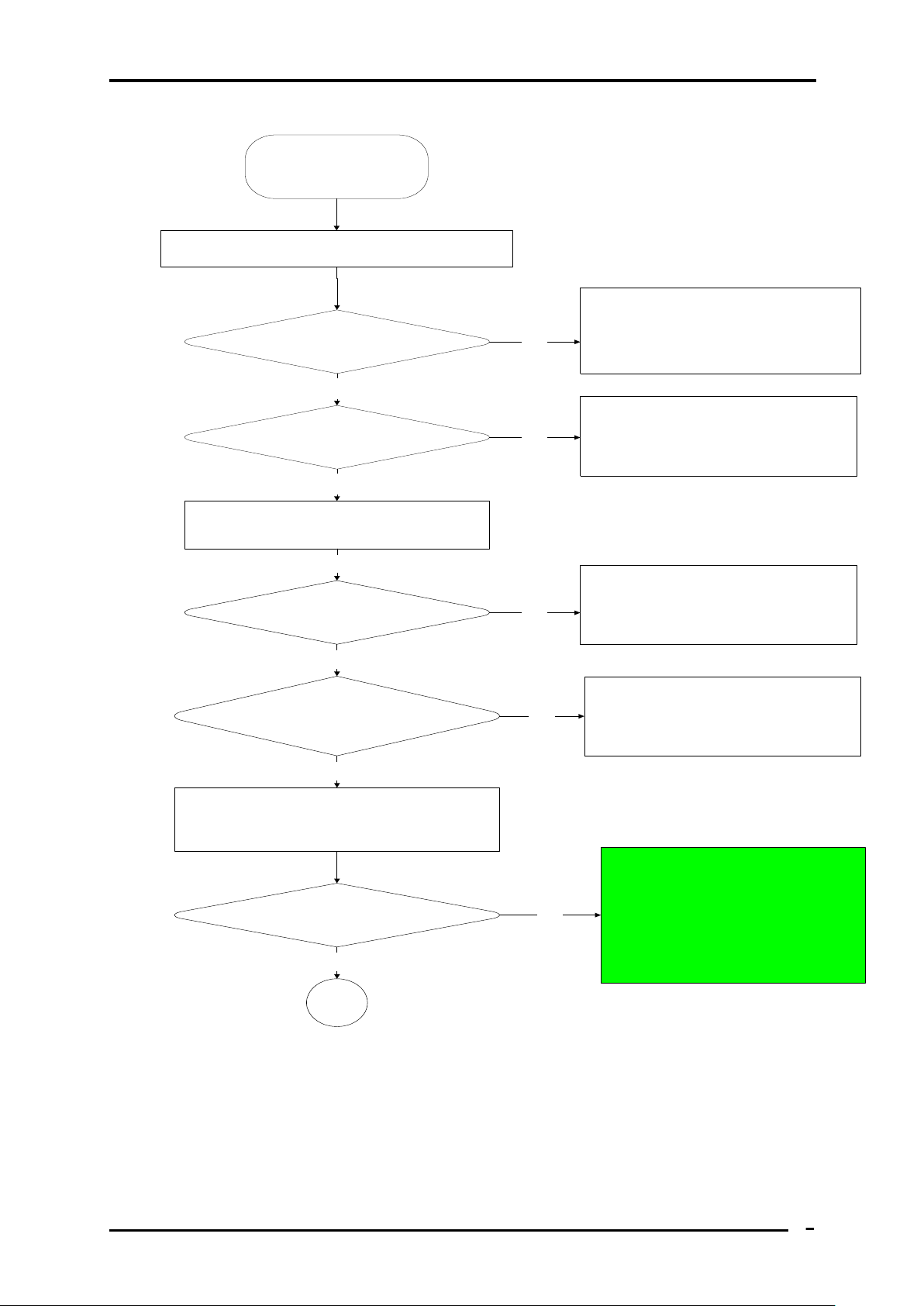
START
Connect the AC adapter to the DC-
IN socket
Is the DC-IN LED on?
Is the Battery LED on?
Turn the Power switch on
Is the Power On LED on?
Is the "Toshiba" or "Dynabook"
logo message display?
If the "password" message
displays, type the password, then
press Enter.
Is Toshiba Windows7 being
loaded?
A
Yes
Yes
Yes
Yes
Yes
Yes
Perform the Power Supply
Troubleshooting procedures
in section 2.3
Perform diagnostics
program. Run CM165.EXE
and select the HARD DISK
item.
Perform the Power Supply
Troubleshooting procedures
in section 2.3
No
No
No
No
No
Perform the Power Supply
Troubleshooting procedures
in section 2.3
Perform the Power Supply
Troubleshooting procedures
in section 2.3
Figure 2-1 Troubleshooting flowchart (1/2)
Satellite A660/A665 Series Maintenance Manual
2 Troubleshooting Procedures
6
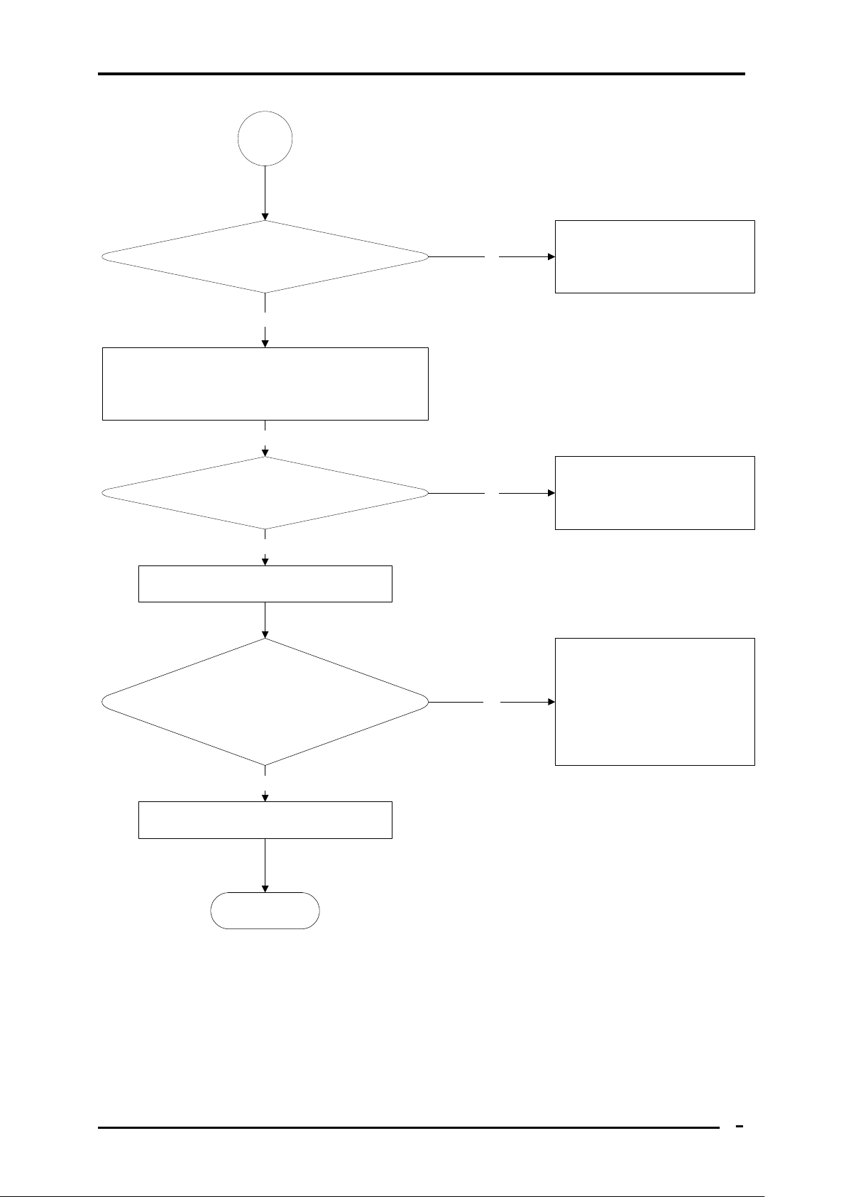
A
Does typed characters appear correctly?
Insert USB memory disk or CD ROM,
Then run the diagnostics test program.
Is the diagnostics test loaded?
Allow each test to perform
automatically
Is an error detected by any of the
diagnostics tests?
System is normal
End
Yes
Yes
Yes
No
Perform the Keyboard
Troubleshooting procedures
in section 2.5
Perform the USB memory
disk or CD ROM
Troubleshooting procedures
in section 2.9
After confirming which
diagnostics test has detected
an error, perform the
appropriate procedure as
outlined below.
No
No
Yes
Figure 2-1 Troubleshooting flowchart (2/2)
Satellite A660/A665 Series Maintenance Manual

2 Troubleshooting Procedures
7
If the diagnostics program cannot detect an error, the problem may be intermittent. The test
program should be executed several times to isolate the problem. When a problem has been
located, perform the appropriate troubleshooting procedures as follows:
1. If an error is detected by the battery test, perform the Power Supply Troubleshooting
procedures in Section 2.3
2. If an error is detected by the display test, perform the Display Troubleshooting
procedures in Section 2.4
3. If an error is detected by the keyboard test, perform the Keyboard Troubleshooting
procedures in Section 2.5
4. If an error is detected by the Touchpad test, perform the Touchpad Troubleshooting
procedures in Section 2.8
5. If an error is detected by the audio test, perform the Speaker Troubleshooting
procedures in Section 2.9 and the Optical Drive Troubleshooting Procedures in
Section 2.10
6. If an error is detected when using the HDD/SSD, perform the HDD/SDD
Troubleshooting procedures in Section 2.15
7. If an error is detected by the 3D sensor test, perform the 3D sensor troubleshooting
Procedures in Section 2.22
8. If an error is detected when using the LAN, perform the LAN troubleshooting
procedures in Section 2.27
Satellite A660/A665 Series Maintenance Manual
 Loading...