

Toshiba Satellite A300-ST3511, Satellite A300, Satellite Pro A300, EQUIUM A300, SATEGO A300 Maintenance Manual

Toshiba Personal Computer
Satellite A300
Satellite Pro A300
EQUIUM A300
SATEGO A300
(PSAG0x/PSAG1x)
(PSAG2x/PSAG3x)
(PSAG4x/PSAG5x)
(PSAG6x/PSAG7x)
Maintenance Manual
TOSHIBA CORPORATION
S/ No
Satellite A300/Satellite Pro A300/EQUIUM A300/SATEGO A300 Maintenance Manual

Copyright
© 2008 by Toshiba Corporation. All rights reserved. Under the copyright laws, this manual
cannot be reproduced in any form without the prior written permission of Toshiba. No patent
liability is assumed with respect to the use of the information contained herein.
Toshiba Satellite A300/Satellite Pro A300/EQUIUM A300/SATEGO A300 Maintenance
Manual
First edition March 2008
Disclaimer
The information presented in this manual has been reviewed and validated for accuracy. The
included set of instructions and descriptions are accurate for theSatellite A300/Satellite Pro
A300/EQUIUM A300/SATEGO A300 at the time of this manual's production. However,
succeeding computers and manuals are subject to change without notice. Therefore, Toshiba
assumes no liability for damages incurred directly or indirectly from errors, omissions, or
discrepancies between any succeeding product and this manual.
Trademarks
Intel and Pentium are registered trademarks of Intel Corporation.
IBM, IBM PC/XT, PC/AT, PS/2 and OS/2 are registered trademarks of IBM Corporation.
Windows Vista home edition are registered trademarks of Microsoft Corporation.
Sound Blaster and Pro are trademarks of Creative Technology Ltd.
UNIX is a registered trademark of X/Open Company Ltd.
NetWare are registered trademarks of Novell, Inc.
All other properties are trademarks or registered trademarks of their respective holders.
ii Satellite A300/Satellite Pro A300/EQUIUM A300/SATEGO A300 Maintenance Manual
Preface
This maintenance manual describes how to perform hardware service maintenance for the
Toshiba Personal Computer Satellite A300/Satellite Pro A300/EQUIUM A300/SATEGO
A300, referred to as Satellite A300/Satellite Pro A300/EQUIUM A300/SATEGO A300 in
this manual.
The procedures described in this manual are intended to help service technicians isolate
faulty Field Replaceable Units (FRUs) and replace them in the field.
SAFETY PRECAUTIONS
Four types of messages are used in this manual to bring important information to your
attention. Each of these messages will be italicized and identified as shown below.
DANGER: “Danger” indicates the existence of a hazard that could result in death or
serious bodily injury, if the safety instruction is not observed.
WARNING: “Warning” indicates the existence of a hazard that could result in bodily
injury, if the safety instruction is not observed.
CAUTION: “Caution” indicates the existence of a hazard that could result in property
damage, if the safety instruction is not observed.
NOTE: “Note” contains general information that relates to your safe maintenance
service.
Improper repair of the computer may result in safety hazards. Toshiba requires service
technicians and authorized dealers or service providers to ensure the following safety
precautions are adhered to strictly.
Be sure to fasten screws securely with the right screwdriver. If a screw is not fully
fastened, it could come loose, creating a danger of a short circuit, which could cause
overheating, smoke or fire.
If you replace the battery pack, RTC battery or backup battery, be sure to use only the
same model battery or an equivalent battery recommended by Toshiba. Installation of
the wrong battery can cause the battery to explode.
Satellite A300/Satellite Pro A300/EQUIUM A300/SATEGO A300 Maintenance Manual iii

The manual is divided into the following parts:
Chapter 1 Hardware Overview describes the Satellite A300/Satellite Pro
A300/EQUIUM A300/SATEGO A300 system unit and each FRU.
Chapter 2 Troubleshooting Procedures explains how to diagnose and resolve
FRU problems.
Chapter 3 Test and Diagnostics describes how to perform test and diagnostic
operations for maintenance service.
Chapter 4 Replacement Procedures describes the removal and replacement of the
FRUs.
Appendices The appendices describe the following:
Handling the LCD module
Board layout
Pin Assignments
Keyboard scan/character codes
Key layout
BIOS Rewrite Procedures
EC/KBC Rewrite Procedures
iv Satellite A300/Satellite Pro A300/EQUIUM A300/SATEGO A300 Maintenance Manual

Conventions
This manual uses the following formats to describe, identify, and highlight terms and
operating procedures.
Acronyms
On the first appearance and whenever necessary for clarification acronyms are enclosed in
parentheses following their definition. For example:
Read Only Memory (ROM)
Keys
Keys are used in the text to describe many operations. The key top symbol as it appears on
the keyboard is printed in boldface type.
Key operation
Some operations require you to simultaneously use two or more keys. We identify such
operations by the key top symbols separated by a plus (+) sign. For example, Ctrl + Pause
(Break) means you must hold down Ctrl and at the same time press Pause (Break). If
three keys are used, hold down the first two and at the same time press the third.
User input
Text that you are instructed to type in is shown in the boldface type below:
DISKCOPY A: B:
The display
Text generated by the XXXXX that appears on its display is presented in the type face
below:
Format complete
System transferred
Satellite A300/Satellite Pro A300/EQUIUM A300/SATEGO A300 Maintenance Manual v

Table of Contents
Chapter 1 Hardware Overview
1.1 Features................................................................................................................................1
1.2 System Unit Components ....................................................................................................9
1.3 2.5-inch HDD.....................................................................................................................15
1.4 DVD Super Multi (+-R Double Layer)..............................................................................16
1.5 HD DVD ROM..................................................................................................................17
1.6 HD DVD-RW ....................................................................................................................18
1.7 Power Supply.....................................................................................................................19
1.8 Batteries .............................................................................................................................20
1.1.1 Main Battery...........................................................................................20
1.1.2 Battery Charging Control.......................................................................20
1.1.3 RTC Battery ...........................................................................................21
Chapter 2 Troubleshooting
2.1 Outline....................................................................................................................2-1
2.2 Basic Flowchart......................................................................................................2-2
2.3 Power Supply .........................................................................................................2-6
Procedure 1 Power Icon Check........................................................................... 2-6
Procedure 2 Connection Check........................................................................... 2-8
Procedure 3 Replacement Check........................................................................ 2-8
2.4 System Board .........................................................................................................2-9
Procedure 3 Replacement Check.................................................................... 2-10
2.5 HDD .....................................................................................................................2-11
Procedure 1 Message Check............................................................................. 2-11
Procedure 2 Partition Check ......................................................................2-11
Procedure 3 Format Check..........................................................................2-12
Procedure 4 Test Program Check ...............................................................2-13
Procedure 5 Connector Check and Replacement Check.............................2-14
vi Satellite A300/Satellite Pro A300/EQUIUM A300/SATEGO A300 Maintenance Manual

2.6 Keyboard..............................................................................................................2-15
Procedure 1 Test Program Check ......................................................................2-15
Procedure 2 Connector Check and Replacement Check....................................2-15
2.7 Display ................................................................................................................. 2-16
Procedure 1 External Monitor Check .........................................................2-16
Procedure 2 Test Program Check ...............................................................2-16
Procedure 3 Connector Check and Replacement Check.............................2-16
2.8 ODD (Optical Disk Drive)...................................................................................2-18
Procedure 1 ODD Cleaning Check.............................................................2-18
Procedure 2 Test Program Check ...............................................................2-18
Procedure 3 Connector Check and Replacement Check.............................2-18
2.9 LAN......................................................................................................................2-20
Procedure 1 Test Program Check ...............................................................2-20
Procedure 2 Connector Check and Replacement Check.............................2-20
2.10 Finger Print(Optional)..........................................................................................2-21
Procedure 1 Test Program Check ...............................................................2-21
Procedure 2 Connector Check ....................................................................2-21
2.11 Audio Test............................................................................................................ 2-22
Procedure 1 Test Program Check ......................................................................2-22
Procedure 2 Connector Check and Replacement Check....................................2-22
2.12 IEEE 1394 Test ....................................................................................................2-23
Procedure 1 Test Program Check ...............................................................2-23
Procedure 2 Connector Check ....................................................................2-23
2.13 Cooling Module....................................................................................................2-24
Procedure 1 Test Program Check ...............................................................2-24
Procedure 2 Connector Check and Replacement Check.............................2-24
Chapter 3 Diagnostic Programs
General ...................................................................................................................... 1
3.1
3.2 Quick Start................................................................................................................. 3
3.2.1 Quick Test ............................................................................................... 3
Satellite A300/Satellite Pro A300/EQUIUM A300/SATEGO A300 Maintenance Manual vii

3.2.2 Customization Test...................................................................................3
3.2.3 Keyboard Layout test ...............................................................................7
3.2.4 Hotkey Test ..............................................................................................8
3.2.5 Audio Play Test........................................................................................8
3.2.6 Audio Record Test ...................................................................................9
3.2.7 DMI Read.................................................................................................9
3.2.8 DMI Write................................................................................................9
3.2.9 System Information................................................................................11
3.2.10 View Logs ..............................................................................................12
3.2.11 Exit to Free DOS...................................................................................12
3.2.12 The Diagnostics Screen Explanation......................................................13
3.3 Options .....................................................................................................................16
3.3.1 Overview ................................................................................................16
3.3.2 Batch Parameters Configuration ............................................................17
3.3.3 Item’s Parameters Configuration ...........................................................19
3.3.4 Load Batch Parameters...........................................................................20
3.3.5 Save Batch Parameters...........................................................................21
3.3.6 LOG Parameters Setting.........................................................................22
3.3.7 Specify LOG Viewer..............................................................................23
3.3.8 Display LOG File...................................................................................23
3.3.9 LOG Viewer...........................................................................................24
3.3.10 LOG File Sample ...................................................................................25
3.4 Subtests.....................................................................................................................27
3.5 System Test ..............................................................................................................30
3.6 Memory Test ............................................................................................................35
3.7 Storage......................................................................................................................41
3.8 Video ........................................................................................................................45
3.9 Communication (COMM)........................................................................................54
3.10 Peripheral .................................................................................................................55
3.11 Error Codes and description.....................................................................................57
3.12 Quick Test Item List...................................................................................................i
viii Satellite A300/Satellite Pro A300/EQUIUM A300/SATEGO A300 Maintenance Manual

Chapter 4 Replacement Procedures
4.1 General ...................................................................................................................4-1
Safety Precautions................................................................................................ 4-2
Before You Begin................................................................................................4-4
Disassembly Procedures ......................................................................................4-5
Assembly Procedures...........................................................................................4-5
Tools and Equipment........................................................................................... 4-6
Screw Tightening Torque ....................................................................................4-6
Colors of Screw Shanks.......................................................................................4-7
Symbols of Screws on the Computer Body......................................................... 4-7
Symbol examples.................................................................................................4-7
Removing the Battery Pack .................................................................................4-8
Installing the Battery Pack...................................................................................4-9
Removing the Optional PC Card .......................................................................4-10
Installing the Optional PC Card.........................................................................4-11
Removing the Momery Card .............................................................................4-12
Installing the Momery Card...............................................................................4-12
Removing the Optional Memory.......................................................................4-13
Installing the Optional Memory......................................................................... 4-14
4.2 HDD .....................................................................................................................4-15
Removing the HDD ...........................................................................................4-15
Installing the HDD.............................................................................................4-17
4.3 ODD Bay Module ................................................................................................4-18
Removing the ODD Bay Module ......................................................................4-18
Installing the ODD Bay Module........................................................................4-19
Disassembling the ODD Bay Module................................................................4-20
Assembling the ODD Bay Module....................................................................4-20
4.4 Keyboard Cover and Keyboard............................................................................4-21
Removing the Keyboard Cover and Keyboard..................................................4-21
Installing the Keyboard Cover and Keyboard ...................................................4-24
4.5 Wireless LAN Card..............................................................................................4-26
Removing the Wireless LAN Card....................................................................4-26
Satellite A300/Satellite Pro A300/EQUIUM A300/SATEGO A300 Maintenance Manual ix

Installing the Wireless LAN Card ..................................................................... 4-27
4.6 MDC Module .......................................................................................................4-28
Removing the MDC Module .............................................................................4-28
Installing the MDC Module ..............................................................................4-29
4.7 Top Cover............................................................................................................. 4-30
Removing the Top Cover................................................................................... 4-30
Installing the Top Cover...................................................................................4-31
4.8 Speakers ............................................................................................................... 4-32
Removing the Speakers......................................................................................4-32
Installing the Speakers.......................................................................................4-32
4.9 Audio Cable..........................................................................................................4-33
Removing the Audio Cable................................................................................ 4-33
Installing the Audio Cable................................................................................. 4-34
4.10 Display Assembly ................................................................................................4-35
Removing the Display Assembly.......................................................................4-35
Installing t the Display Assembly......................................................................4-36
4.11 System Board, AC-IN cable, Fan and Robson card.............................................4-37
Removing the System Board, AC-IN cable, Fan and Robson card...................4-38
Installing the System Board, AC-IN cable, Fan and Robson card.. ..................4-39
4.12 CPU Cooling Module ..........................................................................................4-40
Removing the CPU Cooling and Fan (for VGA Card Model) ..........................4-41
Installing the CPU Cooling and Fan (for VGA Card Model)............................4-42
Removing the CPU Cooling and Fan.................................................................4-43
Installing the CPU Cooling and Fan.................................................................. 4-44
4.13 CPU...................................................................................................................... 4-45
Removing the CPU............................................................................................4-45
Installing the CPU.............................................................................................. 4-46
4.14 USB board, Bluetooth Card, FM card and Felica card ........................................4-48
Removing the USB board, Bluetooth Card, FM card and Felica card ..............4-48
Installing the USB board, Bluetooth Card, FM card and Felica card................4-49
4.15 Display Mask........................................................................................................4-50
Removing the Display Mask..............................................................................4-50
x Satellite A300/Satellite Pro A300/EQUIUM A300/SATEGO A300 Maintenance Manual

Installing the Display Mask............................................................................... 4-52
4.16 FL Inverter Board.................................................................................................4-53
Removing the FL Inverter Board.......................................................................4-53
Installing the FL Inverter Board ........................................................................4-54
4.17 LCD Modules.......................................................................................................4-55
Removing LCD Modules...................................................................................4-55
Installing the LCD Modules .............................................................................. 4-57
4.18 CCD Board and MIC............................................................................................ 4-58
Removing the CCD Board and MIC ................................................................. 4-58
Installing the CCD Board and MIC...................................................................4-59
4.19 Power board, Switch board, Touch Pad board and Finger print board.................... 4-58
Removing Power board, Switch board, Touch Pad board, Finger print board.4-58
Installing Power board, Switch board, Touch Pad board, Finger print board ..4-59
Satellite A300/Satellite Pro A300/EQUIUM A300/SATEGO A300 Maintenance Manual xi

Appendices
Appendix A Handling the LCD Module ...........................................................................A-1
Appendix B Board Layout .................................................................................................B-1
Appendix C Pin Assignments.............................................................................................C-1
Appendix D Keyboard Scan/Character Codes.................................................................. D-1
Appendix E Key Layout.....................................................................................................E-1
Appendix F BIOS Rewrite Procedures..............................................................................F-1
Appendix G EC/KBC Rewrite Procedures........................................................................G-1
xii Satellite A300/Satellite Pro A300/EQUIUM A300/SATEGO A300 Maintenance Manual

Chapter 1
Hardware Overview
i Satellite A300/Satellite Pro A300/EQUIUM A300/SATEGO A300 Maintenance Manual

1 Hardware Overview
ii Satellite A300/Satellite Pro A300/EQUIUM A300/SATEGO A300 Maintenance Manual

1 Hardware Overview
Chapter 1 Contents
1.1 Features............................................................................................................................... 1
1.2 System Unit Components ................................................................................................... 9
1.3 2.5-inch HDD.................................................................................................................... 15
1.4 DVD Super Multi (+-R Double Layer)............................................................................. 17
1.5 HD DVD ROM................................................................................................................. 19
1.6 HD DVD-RW ................................................................................................................... 20
1.7 Power Supply.................................................................................................................... 21
1.8 Batteries ............................................................................................................................ 22
1.1.1 Main Battery.......................................................................................... 22
1.1.2 Battery Charging Control...................................................................... 22
1.1.3 RTC Battery .......................................................................................... 23
Satellite A300/Satellite Pro A300/EQUIUM A300/SATEGO A300 Maintenance Manual iii

1 Hardware Overview
Figures
Figure 1-1 ID Parts Description Placement...............................................................................6
Figure 1-2 Computer Block Diagram........................................................................................7
Figure 1-3 System Board Configurations..................................................................................8
Figure 1-4 System Unit Block Diagram....................................................................................9
Figure 1-5 SATA HDD ...........................................................................................................15
Figure 1-6 DVD Super Multi drive.........................................................................................17
Tables
Table 1-1 HDD Specifications ................................................................................................15
Table 1-2 DVD Super Multi Drive Specifications..................................................................17
Table 1-3 HD DVD ROM Specifications................................................................................19
Table 1-4 HD DVD-RW Specifications..................................................................................20
Table 1-5 Battery specifications..............................................................................................22
Table 1-6 Quick/Normal charging time ..................................................................................23
iv Satellite A300/Satellite Pro A300/EQUIUM A300/SATEGO A300 Maintenance Manual

1 Hardware Overview 1.1 Features
1.1 Features
The Toshiba Satellite A300/Satellite Pro A300/EQUIUM A300/SATEGO A300 is a full size
notebook PC based on the Penryn / Pentium and Merom processor, providing high-speed
processing capabilities and advanced features. The computer employs a Lithium Ion battery
that allows it to be battery-operated for a longer period of time. The display uses 15.4-inch
WXGA LCD panel, at a resolution of 1280 by 800 pixels. The Micro-FCPGA socket
supports BTO/CTO for the CPU so that the system can be designed to suit your needs.
The computer has the following features.
Processor
The CPU is the Penryn Processor and Merom Processor.
Penryn Core2 Duo Processor (800MHz)
T8100(2.20G)/T8300(2.40G) Hz
T9300(2.50G)/T9500(2.60G) Hz
Merom Core2 Duo Processor (800MHz)
T7800(2.6G) Hz
Merom Core2 Duo Processor (667MHz)
T5250(1.50G)/T5450(1.66G) Hz
T5550(1.83G)/T5750(2.00G) Hz
Pentium Dual Core Processor (533MHz)
T2330(1.60G)/T2370(1.73G) Hz
Merom Celeron Processor (533MHz)
540(1.86G)/550(2.0G)/560(2.13G) Hz
Host Bridge System Controller
System Controller: Intel PM965/GM965/GL960 + ICH8M
Graphics
Intel GM965/GL960 integrated graphic or PM965 with ATI M82XT/M86M.
Memory
1 Satellite A300/Satellite Pro A300/EQUIUM A300/SATEGO A300 Maintenance Manual

1 Hardware Overview 1.1 Features
The computer has two SO-DIMMs slot comes standard with DDRII-667MHz module.
It supports PC2-5300 and uses SO-DIMMs (DDRII SDRAM) driven at 1.8 V,
accepting BTO/CTO for your memory requirements. It can incorporate up to 4 GB
for PM/GM965 and 2GB of main memory for GL960.
Using the following sizes of memory modules:
y 512 MB (64M×16×4P)/667 MHZ
y 1024 MB (64M×16×8P)/667 MHZ
y 2048 MB (128Mx8x8P)/667 MHZ
Hard Disk Drive (HDD)
The computer accommodates 9.5 mm and 12.5mm height HDD with following
storage capacities:
y 80 GB (9.5 mm thick) SATA (5,400rpm)
y 120 GB (9.5 mm thick) SATA (5,400rpm)
y 160 GB (9.5 mm thick) SATA (5,400rpm)
y 200 GB (9.5 mm thick) SATA (4,200rpm/5,400rpm)
y 250 GB (9.5 mm thick) SATA (5,400rpm)
y 250 GB (12.5 mm thick) SATA (4,200rpm)
y 300 GB (12.5 mm thick) SATA (4,200rpm)
y 320 GB (9.5 mm thick) SATA (5,400rpm)
y 400 GB (12.5 mm thick) SATA (4,200rpm)
ODD
The computer accommodates a fixed 12.7 mm ODD with one of following types:
y DVD Super Multi +-R Double Layer drive
y DVD Super Multi +-R Double Layer with Label Flash
y HD DVD ROM with super Multi
y HD DVD-RW with super Multi
Display
The LCD displays available come with one of following types:
y 15.4” WXGA CSV 1-Lamp 200nits color display, resolution 1280×800
y 15.4” WXGA 400 CSV WV 72% 2-Lamps display, resolution 1280×800
2 Satellite A300/Satellite Pro A300/EQUIUM A300/SATEGO A300 Maintenance Manual

1.1 Features 1 Hardware Overview
Keyboard
The keyboard has 31 kinds’ countries key.
Battery
The computer has a removable 3/6/9 Cell Lithium Ion battery pack .
Universal Serial Bus (USB) Ports
The computer has four USB 2.0 ports. It is supported to daisy-chain a maximum of
127 USB devices. The serial data transfer rate is 480 Mbps or 12 Mbps and 1.5 Mbps.
These ports support PnP installation and hot plugging.
External Monitor Port
A 15-pin external monitor port is provided, through which the computer automatically
recognizes an external VESA DDC 2B compatible monitor.
Multiple Digital Media Card Slot
This computer is equipped with Multiple Digital Media Card Slot that can
accommodate SD/ Mini-SD/ Micro-SD/ SD-IO/ SDHC/ MS/ MS Pro/ MMC/ XD
memory cards. This slot is for your memory card requirements to provide memory
card read on your computer
Toshiba Pointing Device
Toshiba Pointing Device has one kind of Normal touchpad and one kind of Wide Lux
touchpad with LED light bar for mainstream ID only.
Sound System
The ALC268 integrated audio controller supports multimedia. The sound system
contains the following:
y Stereo speakers
y Headphone / SPDIF combo jack
y Internal microphone
y External microphone jack
LAN (BTO)
Satellite A300/Satellite Pro A300/EQUIUM A300/SATEGO A300 Maintenance Manual 3

1 Hardware Overview 1.1 Features
The internal LAN board supports 10/100Mbit or 1Gbit, enabling connection to a LAN
at up to 1Gbps. It also supports Wake-up on LAN from S3/S4/S5 and PXE boot
support. The LAN board has RJ45 jack to directly accommodate a LAN cable.
Wireless LAN
The internal Mini Card slot supports IEEE802.11bg (MOW)/ IEEE802.11bg (ROW) /
IEEE802.11ag (MOW)/ IEEE802.11ag (ROW)/ IEEE802.11ag (JPN)/
IEEE802.11agn (MOW)/ IEEE802.11agn (ROW)/ IEEE802.11agn (JPN) card. The
Antenna has two or three wires dual band antenna support for BTO.
Internal Modem (BTO)
The computer contains a MDC, enabling data and fax communication. It supports
ITU- T V.90 (for rest countries)/V.92 (America, Canada, UK, Germany & France).
The transfer rates are 56 Kbps for data reception, 33.6 Kbps for data transmission and
14,400 bps for fax transmission. Note, however, that the actual speed depends on the
line quality. The RJ11 modem jack is used to accommodate a telephone line.
IEEE 1394
The IEEE 1394 serial data transfer rate is 400 Mbps, this port supports hot plugging.
Finger Print (BTO)
This product has a fingerprint utility installed for the purpose of enrolling and
recognizing fingerprints. By enrolling the ID and password to the fingerprint authentication device, it is no longer necessary to input the password from the keyboard.
Just by swiping the finger against the fingerprint sensor.
PCI Express Slot
The ICH8-M provides PCI Express root ports which are compliant to the PCI Express
Base Specification, Revision 1.0a. The root port supports 2.5 Gb/s bandwidth in each
direction (5 Gb/s concurrent) and two virtual channels for full isochronous data
support.
CD Key (BTO)
The CD Key supports to play Audio CD directly.
Internal Camera (BTO)
The computer has an internal camera. The camera has VGA (fixed focus) for low
end ID or 1.3Mpix resolution (Auto macro) for mainstream ID support.
4 Satellite A300/Satellite Pro A300/EQUIUM A300/SATEGO A300 Maintenance Manual

1.1 Features 1 Hardware Overview
FELICA card reader (for JAPAN BTO)
The felica card reader writes and reads data to and from contactless Felica IC cards.
Having no need for physical contact with the card, the reader/writer is immune to
performance deterioration caused by wear and contamination, providing easy
maintenance and long term reliability.
The computer has Felica card reader and support BTO for Japan model only.
HDMI Out Port (BTO)
A HDMI monitor can be connected to the HDMI out port on the computer.
The computer has HDMI out port and support BTO for HD DVD SKU only.
S Video Out Port
The S Video out port lets you transfer video data to external devices.
FM Tuner Port (Exclusive with Modem/Felica)
The FM Tuner Port lets you connect an external FM Antenna.
Satellite A300/Satellite Pro A300/EQUIUM A300/SATEGO A300 Maintenance Manual 5
1 Hardware Overview 1.1 Features
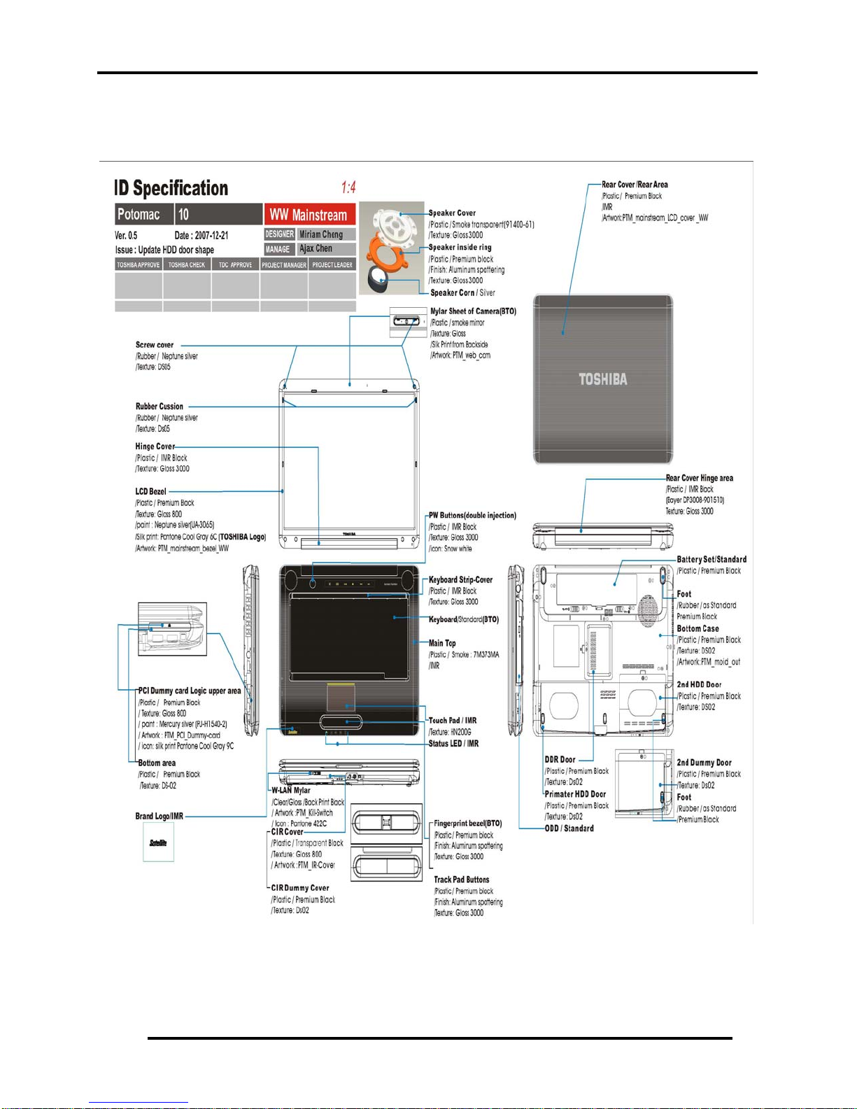
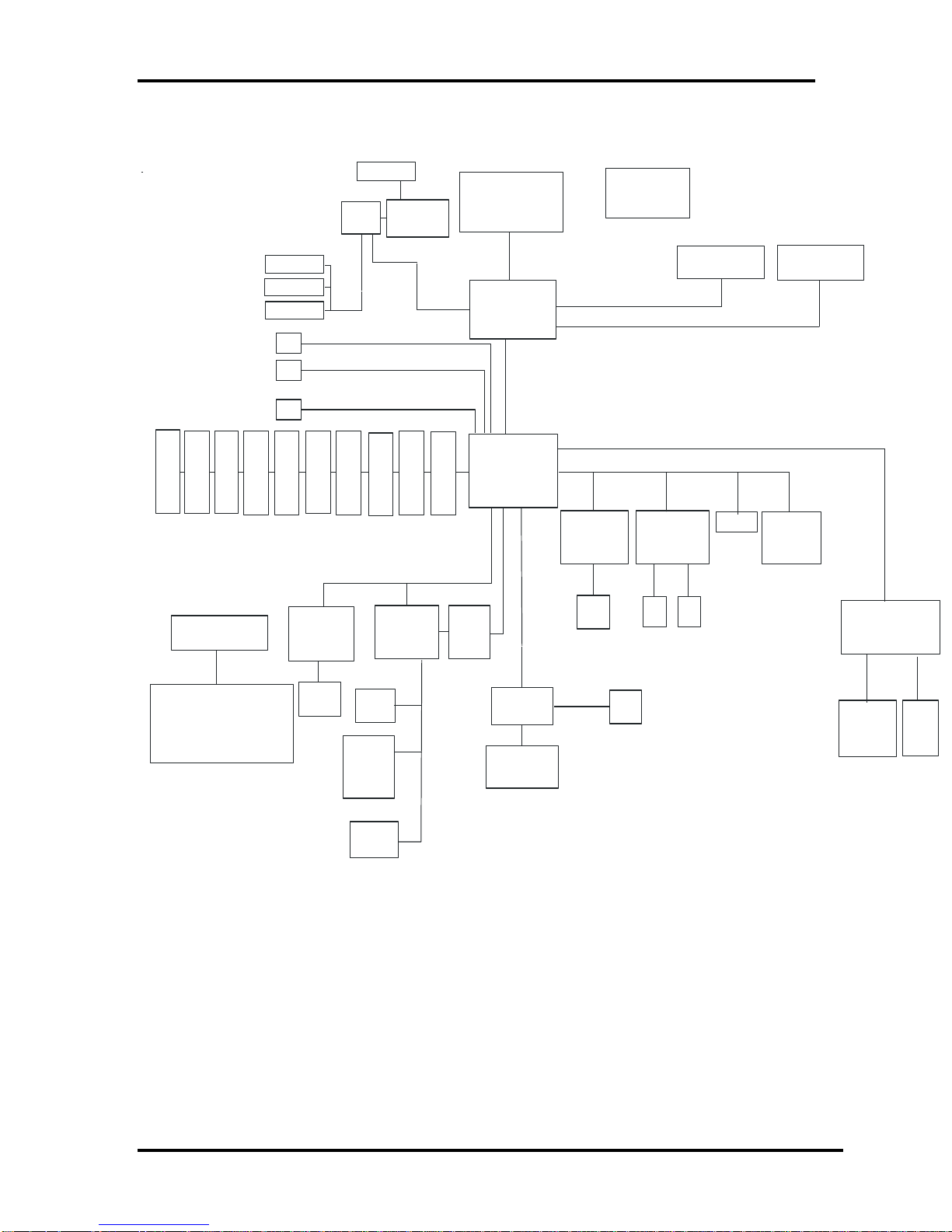
Figures 1-1/1-2/1-3 and 1-4 show the computer and its system unit configuration,
respectively.
Figure 1-1 ID Parts Description Placement
6 Satellite A300/Satellite Pro A300/EQUIUM A300/SATEGO A300 Maintenance Manual
1.1 Features 1 Hardware Overview
HDMI CONN
Mer om
SI L19198
ATI
HDMI Buffer
GP U
SATA_ 0
SATA_ 1
USB7
CA MER A
Re a l t e k
ALC 268
PCIE X16
USB8
FI NGER P RI NT
3. 3V, AZALI A
USB9
S- v i d eo
LCM
CRT
HDD
HDD
USB6
Pr i mar y _I DE
Bl uetooth
ODD
CONN
US B0
CONN
US B 1
BATTERY
CONN
CONN
US B2
US B3
USB4
Expr ess Card
MDC / Modem
Modul e 56K
WL A N
USB5
FELI CA
FM
Tuner
( u FCPGA)
FSB, 667/ 800 MHz
Cr es t l i n e
1299 PCBGA
DMI x4
I CH8 - M
676 BGA
PCI _EXPRESS
I CS9LPRS365
Cl oc k gener at or
1. 8V, DDR2 I nt er f ac e, 533/ 667 MHz
1. 8V, DDR2 I nt er f ac e, 533/ 667 MHz
Real t ek
10/ 100 8101E
8111C
RJ 4 5
MI NI CARD
Wi r el ess LAN
ANT ANT
DDR2 _ SODI MM0 DDR2 _ S ODI MM1
3. 3V, PCI _I nt er f ace, 33MHz
NEWCA RD
MINI CARD
ROBSON
Car d Reader & 1394
RI COH R5 C8 3 3
Sy s t e m Char ger &
DC/ DC S y s t e m power
(IMVP- 6 VR)
3. 3V, LPC_I nt er f ace, 33MHz
RJ 1 1
MI C
JACK
HP
+
SPDI F
JACK
SPEAKER
WINBOND
W775x
BI OS
SPI EEROM
Figure 1-2 Computer Block Diagram
CI R
Car d r eader
CONN
1394
CONN
Satellite A300/Satellite Pro A300/EQUIUM A300/SATEGO A300 Maintenance Manual 7
1 Hardware Overview 1.1 Features
Kensi ngt on
RG B
S- Vi deo
HDMI
Rj 45
USB 1*
1
U SB*
1394
Speak er
Expre ss 1 *
HDD
nd
(
2
WLan
-
CI R
switch
Bat t er y
Speak er
DC- I N
ODD
Rj 11
HDD
)
Bridge
Media
Slot
Vol ume
Mi c r ophone
Headphone
(Primary)
USB* 2
8 Satellite A300/Satellite Pro A300/EQUIUM A300/SATEGO A300 Maintenance Manual
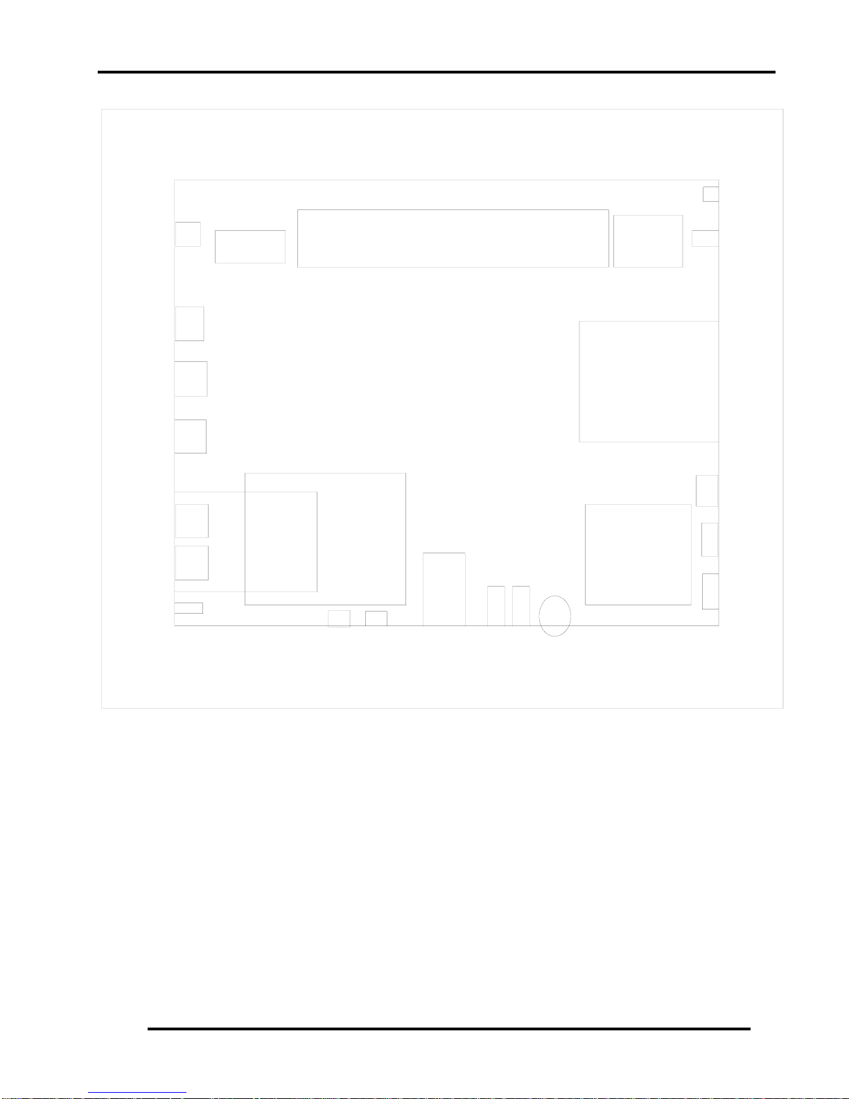
Figure 1-3 System Board Configurations
1.2 System Unit Components 1 Hardware Overview
1.2 System Unit Components
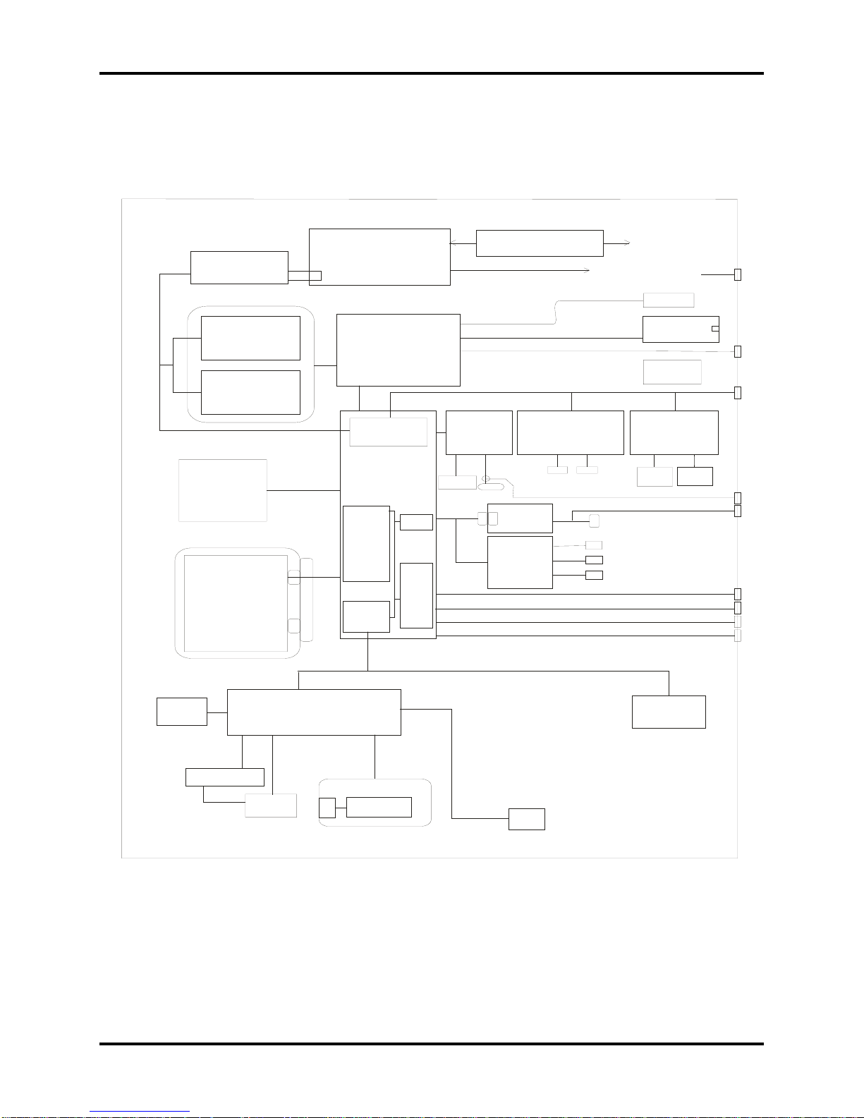
Figure 1-4 is Block Diagram of the System Unit.
CPU Intel
GMT G784
Themal Sensor
C
53
P 00 DDRII
H
667 M z
:
Core2 Duo
/
Merom C eleron M
. ... .
66 6
1G20GHz
uPGA
Clock Generator
()
ICS9LP RS 365
CPU VID
ISL6218
DC
S-Video
Expansion
Memory
512/1024/2048
Expansion
Memory
512/1024/2048
Internal
SATA
- GB
80 4
00
/. mm
9.5125
DVD Super Multi
+-R Double ayer
-
HD DVD ROM
-
HD DVD RW
Flash
ROM
HDD
L
SATA /__0
KBC /
W775C
Intel
GM965
GL960
/
North Bridge
DMI
Intel
ICH -M
1
South Bridge
IDE
Cont.
PCI-PC
Bridge
EC
/
SM Bus
Cont.
8
PM965
Ac97
USB
Cont.
(02)
LAN Cont.
Realtek
8101E
8
111C 1G
EEPROM
Internal LPC
10/100
Rj45
MDC
Modem
CODEC
ALC268
LVDS
Mini PCI Slot
Wireless LAN Card
.//
802 11g ag agn
Antenna
LCD . "
CRT
C
Controller
R5C833
Card
Reader
Rj11
Speaker
MIC
Headphone
W SPDIF
/
SMSC
SIO 1036
15 4
VRAM
ard Bus
1394
.Conn
USB
USB
USB
USB
K/B
KPA AC
1269A
Satellite A300/Satellite Pro A300/EQUIUM A300/SATEGO A300 Maintenance Manual 9
I2C
Main Battery
EEPROM
CIR
Figure 1-4 System Unit Block Diagram

1 Hardware Overview 1.2 System Unit Components
The system unit of the computer consists of the following components:
Processor: Core2 Duo / Dual Core Processor and Merom Celeron Processor.
y Core2 Duo Processor (800MHz)
− Core speed: 2.2/2.4/2.5/2.6GHz
− System bus: 800 MHz
− On-die level 2 cache: 3 MB (T8100/T8300)
− On-die level 2 cache: 4 MB (T7800)
− On-die level 2 cache: 6 MB (T9300/T9500)
y Core2 Duo Processor (667MHz)
− Core speed: 1.66/1.83/2.0GHz
− System bus: 667 MHz
− On-die level 2 cache: 2 MB
y Dual Core Processor (533MHz)
− Core speed: 1.60/1.73GHz
− System bus: 533 MHz
− On-die level 2 cache: 1 MB
y Merom Celeron Processor (533MHz)
− Core speed:1.86/2.0/2.13GHz
− System bus: 533 MHz
− On-die level 2 cache: 1 MB
Memory
Two expansion memory slots are provided. They can hold 512/1024/2048MB expansion
memory modules available as options to grow up to 2GB for GL960 and 4.0 GB for
PM/GM 965.
y PC2-5300/667MHz DDRII SDRAM supported
y 512/1024/2048MB modules supported
− 512 MB (32M x 16 x 8P)
− 1024 MB (64M x 8 x 16P)
− 2048 MB (64M x 16 x 16P)
y 1.8 volt operation
y No parity bit
y 64-bit data transfer
BIOS ROM (Flash EEPROM)
y 8Mb x 1 chip (1024KB flash parts)
10 Satellite A300/Satellite Pro A300/EQUIUM A300/SATEGO A300 Maintenance Manual

1.2 System Unit Components 1 Hardware Overview
− NvStorage size : 128K
− NvStorage free space : 101K
− FV00 size : 624K
− FV00 free space : 49K
− FV01 size : 64K
− FV01 free space : 45K
− FV02 size : 36K
− FV02 free space : 4K
− FV03 size : 20K
− FV03 free space : 2K
− FV04 size : 72K
− FV04 free space : 15K
System Controllers
y North Bridge: Intel PM965/GM965/GL960
− CPU Interface and Control
− System Memory Support
− PCI Express* Graphics (PEG) Interface
− Integrated Display Interface Support
− Internal Graphics Features
− Direct Media Interface (DMI)
− Power Management
− Security and Manageability
− Serial ATA Interface
− ICH8 Audio Control
y South Bridge: Intel ICH8-M
− Direct Media Interface (DMI)
− PCI Express* Interface
− Serial ATA (SATA) Controller
− Advanced Host Controller Interface (AHCI)
− Intel Matrix Storage Technology
− PCI Interface
− IDE Interface
− Low Pin Count (LPC) Interface
− Serial Peripheral Interface (SPI)
− Compatibility Modules
− Advanced Programmable Interrupt Controller (APIC)
− Universal Serial Bus (USB) Controller
− LAN Controller
− RTC
− GPIO
− Enhanced Power Management
Satellite A300/Satellite Pro A300/EQUIUM A300/SATEGO A300 Maintenance Manual 11

1 Hardware Overview 1.2 System Unit Components
− Manageability
− System Management Bus (SMBus 2.0)
− Intel High Definition Audio Controller
− Integrated FAN Speed Control
Card Bus Controller
y R5C833
− PCI-1394 bridge interface
− SD/Mini SD/SD-IO/MS/MS Pro/MMC/XD Card Controller
− PCI Bus interface
Audio Controller
Realtek ALC268 integrated audio controller supports multimedia. The sound system
feature contains the following:
y 2 Stereo DACs support 16/20/24-bit PCM format for stereo audio playback.
y 2 stereo ADCs support 16/20-bit PCM format for two stereo independent sound inputs.
y 16/20/24-bit S/PDIF-OUT supports 44.1K/48K/88.2K/96K/192KHz sample rate.
y All ADCs support 44.1K/48K/96KHZ sample rate.
y 4 GPIOs(GPIO0/GPIO3 are digital GPIO shared with digital MIC interface,
GPIO1/GPIO2 are analog) for customized applications.
y High quality analog differential CD input.
y 2 jack detection pins each designed to detect up to 4 jacks.
y Supports hardware digital volume control for digital microphone input.
y Supports external PCBEEP input and built-in digital BEEP generator.
−
KBC/EC (Keyboard Controller/Embedded Controller)
A single KBC W775X chip is used to serve as KBC/ EC and Super IO.
y KBC
− Scan controller function
− Interface controller function
y EC
− Power supply sequence control
− Overheat shutdown support
− LED control
− Beep control
− Device ON/OFF
12 Satellite A300/Satellite Pro A300/EQUIUM A300/SATEGO A300 Maintenance Manual

1.2 System Unit Components 1 Hardware Overview
− Cooling fan speed control
− Universal I/O port
− Battery capacity check
− Flash memory reprogramming function
− EC access interface
− I2C communication control
Battery EEPROM
y 24C02 equivalent (128 words x 16 bits, I2C interface) integrated in battery pack.
− Storing records of battery use
Clock Generator
y ICS9LPRS365
− Generating the clock signal required for the syste
Modem Controller
Built-in MDC card with Askey / Foxconn. Functions of modem controller:
y Digital signal conductor protection
y Ring wake-up support
y Azalia interface
y Communication codes supported:
− For data communication:
V.90 (China)/V.92, data rates: 28kbps/56kbps
V.34 extended rates: 33.6K/2400/V.32 turbo, V.32 bits and fallbacks
− For fax:
V.17, V.27, V.29, V.34 and V.21 Channel 2
V.253 Class 1 fax
LAN Controller
y Realtek 8101E 10/100Mbit or 8111C 10/100Mbit/1Gbit
− IEEE 802.3 10BASE-T/100BASE-TX compliant physical
layer interface
− IEEE 802.3u Auto-Negotiation support
− Digital Adaptive Equalization control
− 10BASE-T auto-polarity correction
− LAN Connect interface
− Automatic detection of “unplugged mode”
− Remote boot (PXE 2.1)
Satellite A300/Satellite Pro A300/EQUIUM A300/SATEGO A300 Maintenance Manual 13

1 Hardware Overview 1.2 System Unit Components
− Smart power down when link is not detected
Wireless LAN Controller
y Support following 3 kinds of mini PCI wireless LAN cards
− IEEE 802.11bg
− IEEE 802.11ag
− IEEE 802.11agn
y Data Rate
− IEEE 802.11bg: Standard 54M bps
− IEEE 802.11ag: Standard 54M bps
− IEEE 802.11agn: Standard 130M bps
y Frequency Channel
− IEEE802.11bg: 2.4GHz
− IEEE802.11ag: 2.4GHz / 5.4GHz
− IEEE802.11agn: 2.4GHz / 5.4GHz
14 Satellite A300/Satellite Pro A300/EQUIUM A300/SATEGO A300 Maintenance Manual
 Loading...