

Toshiba Satellite 1700 Series Replacement Manual
FIELD REPLACEABLE UNIT DOCUMENTATION
1700 Series
Satellite
TM
TM
1700 Series
Satellite
TM
1700 Series
Satellite
GENERAL INFORMATION
TM
1700 Series
Satellite
TM
TM
1700 Series
Satellite
TM
1700 Series
Satellite
GENERAL INFORMATION
TM
1700 Series
Satellite
TM
TM
1700 Series
Satellite
TM
1700 Series
Satellite
TM
1700 Series
Satellite
TM
TM
1700 Series
Satellite
TM
1700 Series
Satellite
GENERAL INFORMATION
TM
1700 Series
Satellite
TM
TM
1700 Series
Satellite
TM
1700 Series
Satellite
GENERAL INFORMATION
TM
1700 Series
Satellite
GENERAL INFORMATION
TM
1700 Series
Satellite
TM
TM
1700 Series
Satellite
TM
1700 Series
Satellite
TM
1700 Series
Satellite
TM
TM
1700 Series
Satellite
TM
1700 Series
Satellite
TM
1700 Series
Satellite
TM
TM
1700 Series
Satellite
TM
TM
1700 Series
Satellite
TM
1700 Series
Satellite
TM
TM
TM
Satellite
1700 Series
GENERAL INFORMATION
Tools Required for Proper
Disassembly and Reassembly:
1. Phillips Screwdriver (Size 1)
2. Flat head screwdriver (5mm)
Before attempting any of the following procedures,
make sure that the main battery and AC adaptor is
not connected to the unit and the environment in
which you are working on is protected from
Electro-Static Discharge(ESD).
3. Hex driver (5mm)
4. Case Separator
5. ESD Wrist Strap
6. ESD mats
7. Tweezers
TOSHIBA
Tough Enough for Today’s World
FIELD REPLACEABLE UNIT DOCUMENTATION
TM
Satellite
1700Series
TABLE OF CONTENTS:
1. BATTERY PACK REMOVAL
2. OPTIONAL PC CARD REMOVAL
3. MEMORY MODULE REMOVAL
4. KEYBOARD REMOVAL
5. TOP COVER REMOVAL
6. HDD REMOVAL
7. FDD REMOVAL
8. SYSTEM BOARD REMOVAL
9. CD-ROM DRIVE REMOVAL
10. MODEM MODULE REMOVAL
11. COOLING MODULE REMOVAL
12. CPU REMOVAL
13. LED BOARD REMOVAL
14. HINGE BRACKET REMOVAL
15. AUDIO BOARD REMOVAL
16. AUDIO/MEMBRANE SWITCH REMOVAL
17. 12.1’’ DISPLAY MASK REMOVAL
18. FL INVERTER AND 12.1’’ LCD REMOVAL
19. 13.3’’ DISPLAY MASK REMOVAL
20. FL INVERTER AND 13.3’’ LCD REMOVAL
TOSHIBA
Tough Enough for Today’s World.
FIELD REPLACEABLE UNIT DOCUMENTATION
TM
Satellite
1700Series
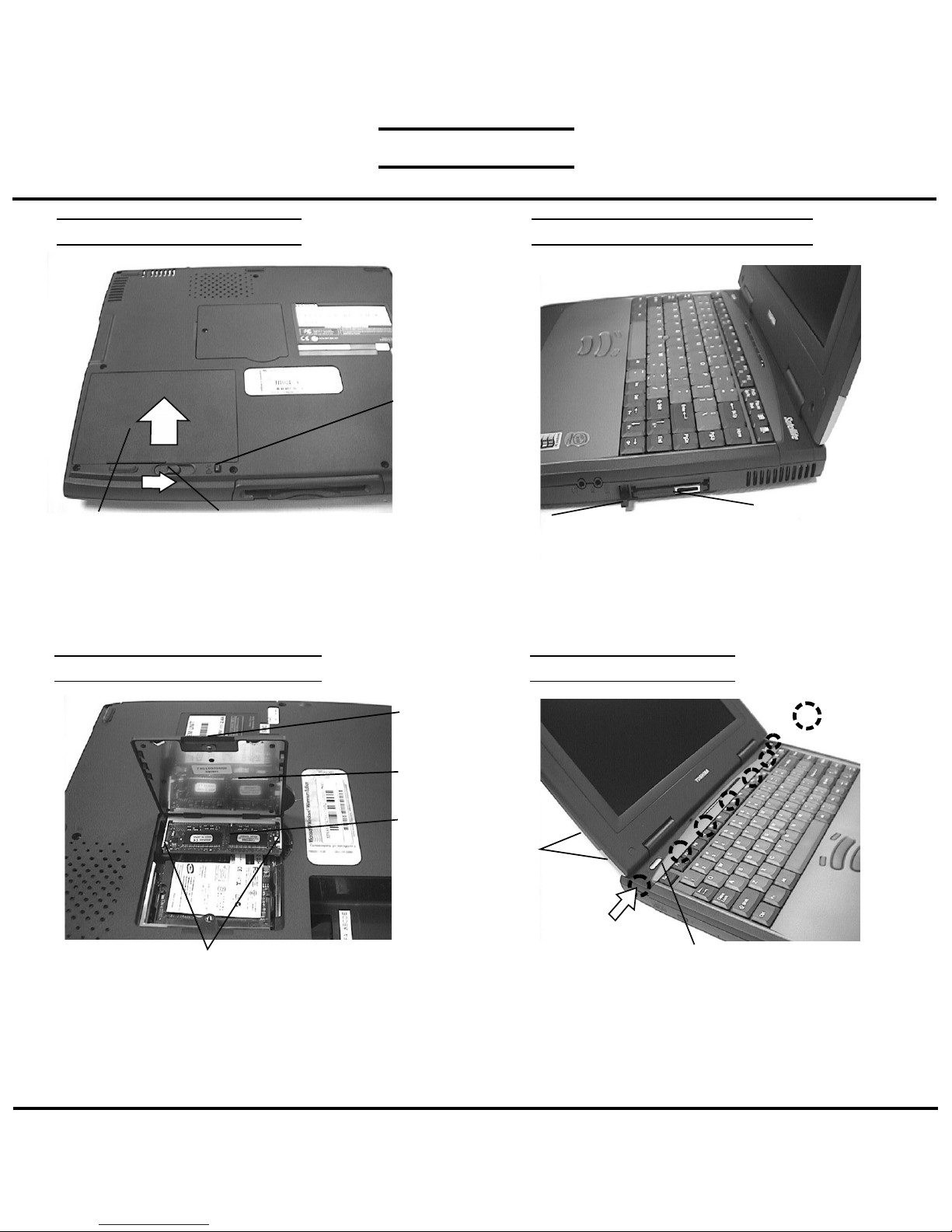
BATTERY PACK REMOVAL OPTIONAL PC CARD REMOVAL
Battery lock
Battery pack
1. Turn the computer upside down as shown.
2. Press the battery lock and slide the
battery release lever to the right and lift out the battery.
Battery release lever
MEMORY MODULE REMOVAL
M2x4 black
screws
Memory
cover
Memory
module
Memory clips
1. Turn the computer upside down.
2. Remove two M2x4 black screws and remove the
memory cover.
3. Push the memory clips outward and pull the
memory module out of the connector on a
30 degree angle.
Eject button
1. Pull out the eject button of the PC card to be
removed.
2. Press the eject button and remove the PC card.
NOTE: Before removing any PCMCIA device, make
sure it is “STOPPED” in the PC Card Manager.
PC card
KEYBOARD REMOVAL
M2.5x3
black screws
Keyboard holder
1. Open the display panel.
2. Remove two M2.5x3 black screws securing the
keyboard holder.
3. Unlatch the keyboard holder at the top of keyboard
starting from the left side.
Latch
TOSHIBA
Tough Enough for Today’s World
 Loading...