

Page 1
FIELD REPLACEABLE UNIT DOCUMENTATION
1700 Series
Satellite
TM
TM
1700 Series
Satellite
TM
1700 Series
Satellite
GENERAL INFORMATION
TM
1700 Series
Satellite
TM
TM
1700 Series
Satellite
TM
1700 Series
Satellite
GENERAL INFORMATION
TM
1700 Series
Satellite
TM
TM
1700 Series
Satellite
TM
1700 Series
Satellite
TM
1700 Series
Satellite
TM
TM
1700 Series
Satellite
TM
1700 Series
Satellite
GENERAL INFORMATION
TM
1700 Series
Satellite
TM
TM
1700 Series
Satellite
TM
1700 Series
Satellite
GENERAL INFORMATION
TM
1700 Series
Satellite
GENERAL INFORMATION
TM
1700 Series
Satellite
TM
TM
1700 Series
Satellite
TM
1700 Series
Satellite
TM
1700 Series
Satellite
TM
TM
1700 Series
Satellite
TM
1700 Series
Satellite
TM
1700 Series
Satellite
TM
TM
1700 Series
Satellite
TM
TM
1700 Series
Satellite
TM
1700 Series
Satellite
TM
TM
TM
Satellite
1700 Series
GENERAL INFORMATION
Tools Required for Proper
Disassembly and Reassembly:
1. Phillips Screwdriver (Size 1)
2. Flat head screwdriver (5mm)
Before attempting any of the following procedures,
make sure that the main battery and AC adaptor is
not connected to the unit and the environment in
which you are working on is protected from
Electro-Static Discharge(ESD).
3. Hex driver (5mm)
4. Case Separator
5. ESD Wrist Strap
6. ESD mats
7. Tweezers
Download Free Service Manual at http://printer1.blogspot.com
TOSHIBA
Tough Enough for Today’s World
Page 2

FIELD REPLACEABLE UNIT DOCUMENTATION
TM
Satellite
1700Series
TABLE OF CONTENTS:
1. BATTERY PACK REMOVAL
2. OPTIONAL PC CARD REMOVAL
3. MEMORY MODULE REMOVAL
4. KEYBOARD REMOVAL
5. TOP COVER REMOVAL
6. HDD REMOVAL
7. FDD REMOVAL
8. SYSTEM BOARD REMOVAL
9. CD-ROM DRIVE REMOVAL
10. MODEM MODULE REMOVAL
11. COOLING MODULE REMOVAL
12. CPU REMOVAL
13. LED BOARD REMOVAL
14. HINGE BRACKET REMOVAL
15. AUDIO BOARD REMOVAL
16. AUDIO/MEMBRANE SWITCH REMOVAL
17. 12.1’’ DISPLAY MASK REMOVAL
18. FL INVERTER AND 12.1’’ LCD REMOVAL
19. 13.3’’ DISPLAY MASK REMOVAL
20. FL INVERTER AND 13.3’’ LCD REMOVAL
Download Free Service Manual at http://printer1.blogspot.com
TOSHIBA
Tough Enough for Today’s World.
Page 3
FIELD REPLACEABLE UNIT DOCUMENTATION
TM
Satellite
1700Series
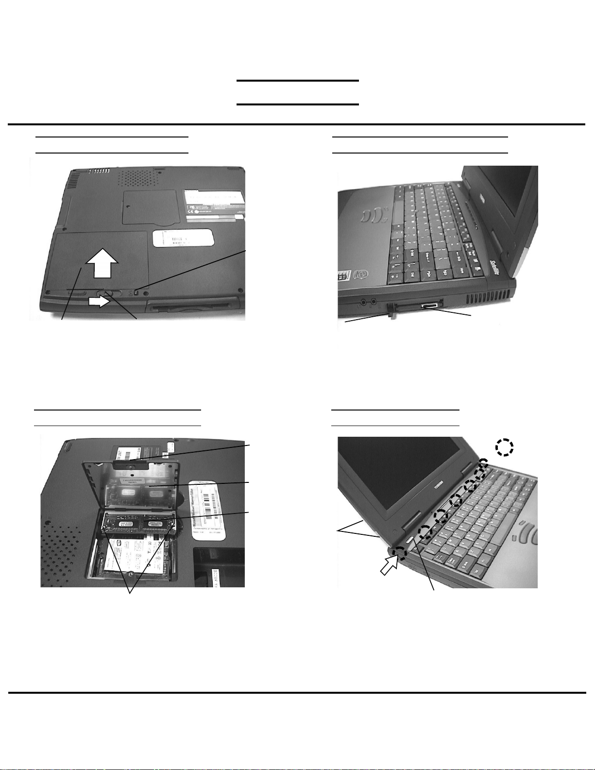
BATTERY PACK REMOVAL OPTIONAL PC CARD REMOVAL
Battery lock
Battery pack
1. Turn the computer upside down as shown.
2. Press the battery lock and slide the
battery release lever to the right and lift out the battery.
MEMORY MODULE REMOVAL
Memory clips
1. Turn the computer upside down.
2. Remove two M2x4 black screws and remove the
memory cover.
3. Push the memory clips outward and pull the
memory module out of the connector on a
30 degree angle.
Battery release lever
M2x4 black
screws
Memory
cover
Memory
module
Download Free Service Manual at http://printer1.blogspot.com
Eject button
1. Pull out the eject button of the PC card to be
removed.
2. Press the eject button and remove the PC card.
NOTE: Before removing any PCMCIA device, make
sure it is “STOPPED” in the PC Card Manager.
KEYBOARD REMOVAL
M2.5x3
black screws
Keyboard holder
1. Open the display panel.
2. Remove two M2.5x3 black screws securing the
keyboard holder.
3. Unlatch the keyboard holder at the top of keyboard
starting from the left side.
PC card
Latch
TOSHIBA
Tough Enough for Today’s World
Page 4

FIELD REPLACEABLE UNIT DOCUMENTATION
TM
Satellite
1700Series
KEYBOARD REMOVAL
Keyboard
M2.5x3 black screws
4. Remove four M2x4 black screws securing the
keyboard.
TOP COVER REMOVAL
Lcd harness assy
1. Remove two M2.5x8 silver screws and M2.5x12 black
screws securing the LCD assembly.
2. Remove one M2.5x3 black screw securing the
LCD harness assembly.
3. Disconnect the LCD harness assembly from the system
board.
Download Free Service Manual at http://printer1.blogspot.com
M2.5x3 black screw
Keyboard
M2.5x8
silver
screws
M2.5x12
black
screws
Keyboard cable
5. Set the keyboard as shown above.
6. Disconnect the keyboard cable from JP7 and
IPS cable from JP5.
7. Lift out the keyboard.
M2.5x18
black
screws
4. Remove eight M2.5x18 black screws and one
M2.5x10 black screw securing the bottom cover.
JP7
M2.5x10 black screw
JP5
IPS cable
TOSHIBA
Tough Enough for Today’s World
Page 5

FIELD REPLACEABLE UNIT DOCUMENTATION
TM
Satellite
1700Series
TOP COVER REMOVAL HDD REMOVAL
M2.5x3
black
screws
LED cable
M2.5x8
silver
screws
JP4 Top cover
5. Disconnect the sound/IPS switch board from JP4 on the
system board.
6. Disconnect the LED board cable from the LED board.
7. Remove four M2.5x8 silver screws and two M2.5x3
black screw securing the top cover assembly.
8 Remove the top cover.
Sound/IPS switch board
HDD REMOVAL
M2.5x4 silver
screws
HDD bracket
HDD assy
handle
HDD assy
HDD
M2.5x8 silver screw
1. Remove one M2.5x8 silver screw securing the
HDD assembly.
2. Grasp the HDD assembly handle and pull it
in the direction of the arrow.
3. Lift out the HDD assembly.
.
FDD REMOVAL
JP6
FDD
cable
M2.5x8
silver
screw
HDD
4. Remove four M2.5x3 silver screws securing the HDD
bracket.
5. Remove the HDD from the HDD bracket.
Download Free Service Manual at http://printer1.blogspot.com
TOSHIBA
Tough Enough for Today’s World
FDD assembly
1. Remove one M2.5x8 silver screw securing the FDD
assembly.
2. Disconnect the FDD cable from JP6.
3. Lift out the FDD assembly.
Page 6

FIELD REPLACEABLE UNIT DOCUMENTATION
TM
Satellite
1700Series
FDD REMOVAL
Left bracket
FDD cable
Right bracket
FDD
M2.5x3 black screws
1. Remove three M2.5x3 black screws securing the
left and right brackets.
2. Lift out the FDD and remove the FDD cable.
SYSTEM BOARD REMOVAL
SYSTEM BOARD REMOVAL
M2.5x8
silver
screws
Hex screws
1. Remove four hex screws at the rear of the computer.
2. Remove two M2.5x8 silver screws near the cooling
module.
CD-ROM DRIVE REMOVAL
System board
3. Push the PC Card eject button and lift out the
system board as shown above.
Download Free Service Manual at http://printer1.blogspot.com
TOSHIBA
PC card
eject button
CD-ROM
drive assy
M2.5x3 black screws
1. Remove two M2.5x3 black screws securing the
CD-ROM drive assembly.
2. Slide the CD-ROM drive assembly to the left
to disconnect from system board.
3. Remove all the CD-ROM brackets.
Tough Enough for Today’s World
Page 7

FIELD REPLACEABLE UNIT DOCUMENTATION
TM
Satellite
1700Series
MODEM MODULE REMOVAL
Modem
cable
Modem
Mini PCI clips
1. Disconnect the modem cable from the modem board.
2. Spread the mini PCI clips securing the modem board
and remove the modem board on a 30 degree angle.
CPU REMOVAL
COOLING MODULE REMOVAL
Cooling
module
Fan cable
JP16
Brass screws
1. Disconnect the fan cable from JP16 on the system
board.
2. Remove three brass screws securing the cooling
module.
3. Lift out the cooling module.
LED BOARD REMOVAL
Open
CPU lock
slot
Lock
1. Using a 5mm flat head screw driver, insert the screwdriver
into the CPU lock slot and turn it counterclockwise.
NOTE: In order to properly lock the CPU, a 5mm flat head
screwdriver must be used.
Download Free Service Manual at http://printer1.blogspot.com
LED
board
M2.5x3 black screws
1. Remove two M2.5x3 black screws securing the
LED board.
2. Lift out the LED board.
TOSHIBA
Tough Enough for Today’s World
Page 8

FIELD REPLACEABLE UNIT DOCUMENTATION
TM
Satellite
1700Series
HINGE BRACKET REMOVAL
1. Remove five M2.5x4 silver screws securing
hinge bracket.
2. Lift out the hinge bracket.
AUDIO/MEMBRANE SWITCH REMOVAL
M2.5x4
silver
screws
AUDIO BOARD REMOVAL
Audio
board
Audio cable
1. Disconnect the audio cable from the audio board.
2. Remove two M2.5x4 silver screws securing the
audio board.
3. Lift out the Audio board.
M2.5x4
silver
screws
1. Remove four M2.5x4 silver screws securing the metal
plate.
2. Lift out the metal plate
Download Free Service Manual at http://printer1.blogspot.com
Audio/membrane switch
cable
Audio cable
M2.5x4
silver
screws
Left speaker
1. Remove two M2.5x4 silver screws securing
the audio/membrane switch board.
2. Disconnect the left and right speakers from
JP3 and JP4.
3. Disconnect the audio and the audio/membrane switch
cables.
JP3
JP4
Right speaker
TOSHIBA
Tough Enough for Today’s World
Page 9

FIELD REPLACEABLE UNIT DOCUMENTATION
TM
Satellite
1700Series
12.1” DISPLAY MASK REMOVAL
Latch
Display
mask
LCD
Mask seals
1. Remove four mask seals at each corner of the
display assembly.
2. Remove four M2.5x5 brass screws securing the
display mask.
3. There are 22 latches securing the display mask.
Carefully insert your fingers between the display mask
and the LCD module and pry open the latches starting
from the top six latches, to the five latches on the right
and left sides, ending with the six bottom latches.
FL INVERTER AND 12.1” LCD REMOVAL
LCD module
M2x5
brass
screws
LCD/FL inverter cable
1. Remove two M2.5x5 black screw securing
FL inverter board.
2. Carefully lift up the FL inverter board and
disconnect the LCD/FL inverter cable from CN1 and
the FL cable from CN2.
3. Remove four M3X6 brass screws securing the
LCD module.
4. Carefully rotate the LCD module from right to left
of the LCD cover.
5. Disconnect the LCD/FL inverter cable from the LCD
module and remove the LCD from the computer.
FL inverter board
FL cable
M2.5x5
black
screws
Download Free Service Manual at http://printer1.blogspot.com
TOSHIBA
Tough Enough for Today’s World
Page 10

FIELD REPLACEABLE UNIT DOCUMENTATION
TM
Satellite
1700Series
13.3” DISPLAY MASK REMOVAL
Latch
Display
mask
LCD
Mask seals
1. Remove four mask seals at each corner of the
display assembly.
2. Remove four M2.5x5 black screws securing the
display mask.
3. There are 22 latches securing the display mask.
Carefully insert your fingers between the display mask
and the LCD module and pry open the latches starting
from the top six latches, to the five latches on the right
and left sides, ending with the six bottom latches.
FL INVERTER AND 13.3”LCD REMOVAL
LCD module
M2x5
brass
screws
LCD/FL inverter cable cable
1. Remove one M2.5x5 black screw securing
FL inverter board.
2. Carefully lift up the FL inverter board and
disconnect the LCD/FL inverter cable from CN1
and the FL cable from CN2.
3. Remove four M2X2 black screws securing the
LCD module.
4. Carefully rotate the LCD module from right to left
of the LCD cover.
5. Disconnect the LCD/FL inverter cable from the LCD
module and remove the LCD from the computer.
FL cable
FL cable
M2.5x5
black
screws
Download Free Service Manual at http://printer1.blogspot.com
TOSHIBA
Tough Enough for Today’s World
 Loading...