


Satellite 1400/1405 Series
General Specifications
1400-S151 1400-S152
PS140U-027XF7 PS140U-027XF3
1405-S151 1405-S152
PS140U-027XFX PS140U-027XFJ
Processor: Intel Celeron 1.20GHz; Integrated co-processor; 256KB Level 2 cache integrated on die; 133MHz front side bus clock
speed
Memory: 256MB SDRAM, expandable to 1024MB; Expansion memory: SODIMM expansion memory
128/256/512Mbit PC133 SDRAM, 3.3V
Data/Address Bus Width: 64-bit/32-bit; BIOS ROM: 4Mbit, CMOS Flash EPROM, Ali M1535 Chipset
Drive(s): HDD: 30.0GB supports PIO Mode 4
FDD: 3.5" 1.44MB
DVD-ROM/CDRW
Graphics/Video: 14.1" TFT active -matrix display; internal display supports up to 16M colors at 1024 x 768; Trident CyberALADDIN-T
graphics controller; 16MB external UMA video memory; 3D graphics accelerator, AGP bus support; 2D graphics
accelerator, BitBLT hardware, hardware cursor, Direct Draw support
Audio: AK4543 Codec Chip; Ali M1535 Sound Chip, 16-bit stereo; Built-in stereo speakers; Direct 3D sound; DirectSound
(supported by driver) and DirectMusic; Full duplex and MIDI (play back) support; Sound Volume Control Dial;
headphone and microphone ports
Communication: Integrated V.90/56K modem, Data and fax support; Integrated 10/100 Ethernet LAN
Expansion: 2 expansion memory slots; 2PC card slots support 2 Type II or 1 Type III PC cards; 32-bit CardBus ready
Ports: RGB (monitor); ECP Parallel printer; 3 USB; RJ-45 LAN; RJ-11 modem; Infrared; TV-Out (NTSC/PAL output; RCA
jack)
Keyboard: 85 keys with 12 function keys, TouchPad pointing device
Battery: 9 cell, rechargeable, removable Li-Ion, approximately 3H battery life
Weight: 7.4 lbs
Dimensions: (L)12.8" x (W)11.2" x (H)1.7"
Software: MS Windows XP Pro pre-installed (1400-S151/1405-S152); MS Windows XP Home pre-installed (1405-S151/1400-
S152); MS Internet Explorer, Online documentation, Adobe Acrobat Reader, Intuit Quicken Basic 2001, Norton
Antivirus 2002, AOL (3-month offer), Toshiba custom utilities, Toshiba great software offer; Lotus SmartSuite
Millennium Edition (1405 Series only)
Security: Slot for computer lock; Main battery pack (sliding lock); HDD and memory (by screw only), Built-in Modem/LAN
(screw only), User Power-On password, Setup Security, HDD password, Keyboard lock (by hotkey), Screen Blank (by
hotkey), Screen Saver (by software)
Warranty: 1 year parts, labor, and battery
Toshiba TRR Page 1 7/02, Satellite
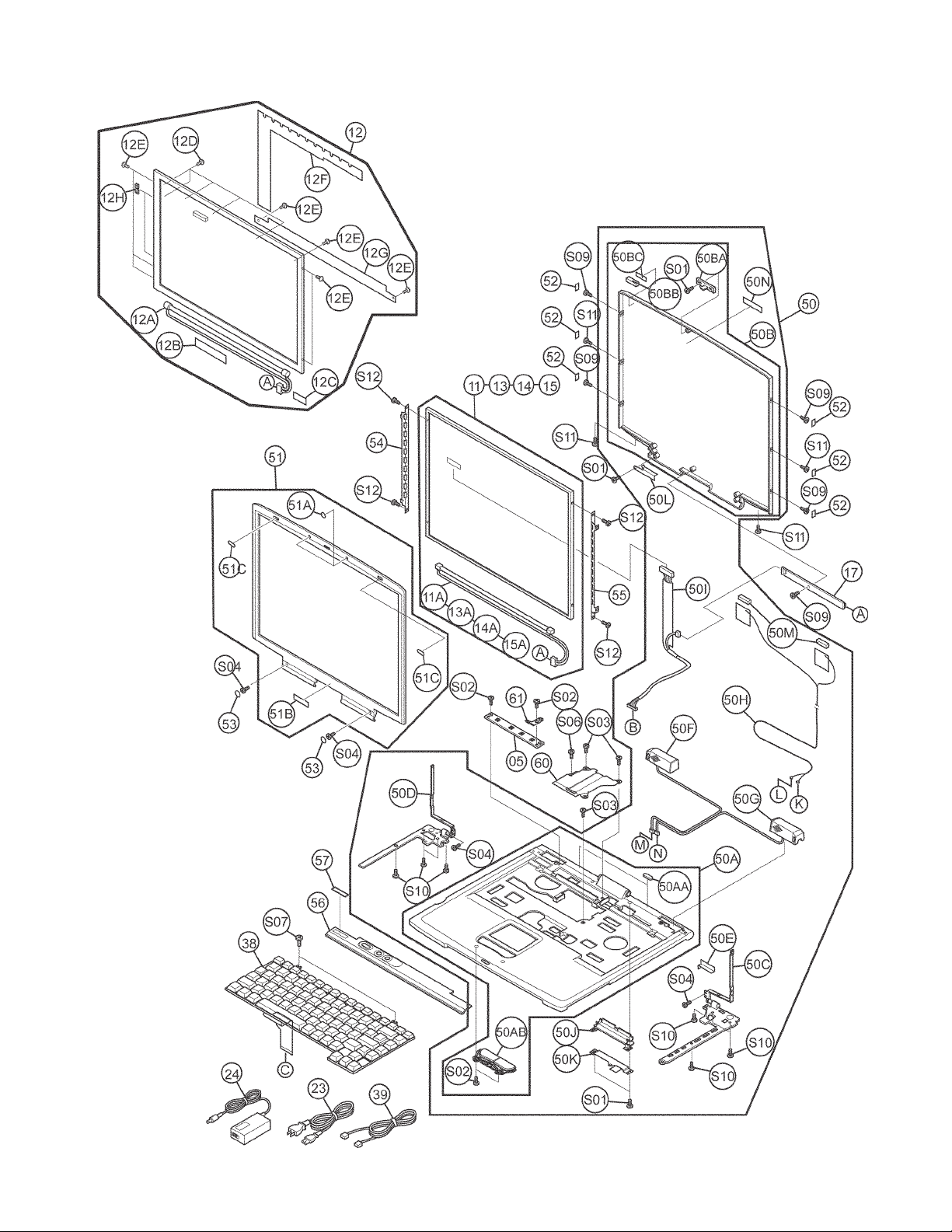
Satellite 1400 Series Exploded Upper View
7/02, SatelliteToshiba TRR Page 2
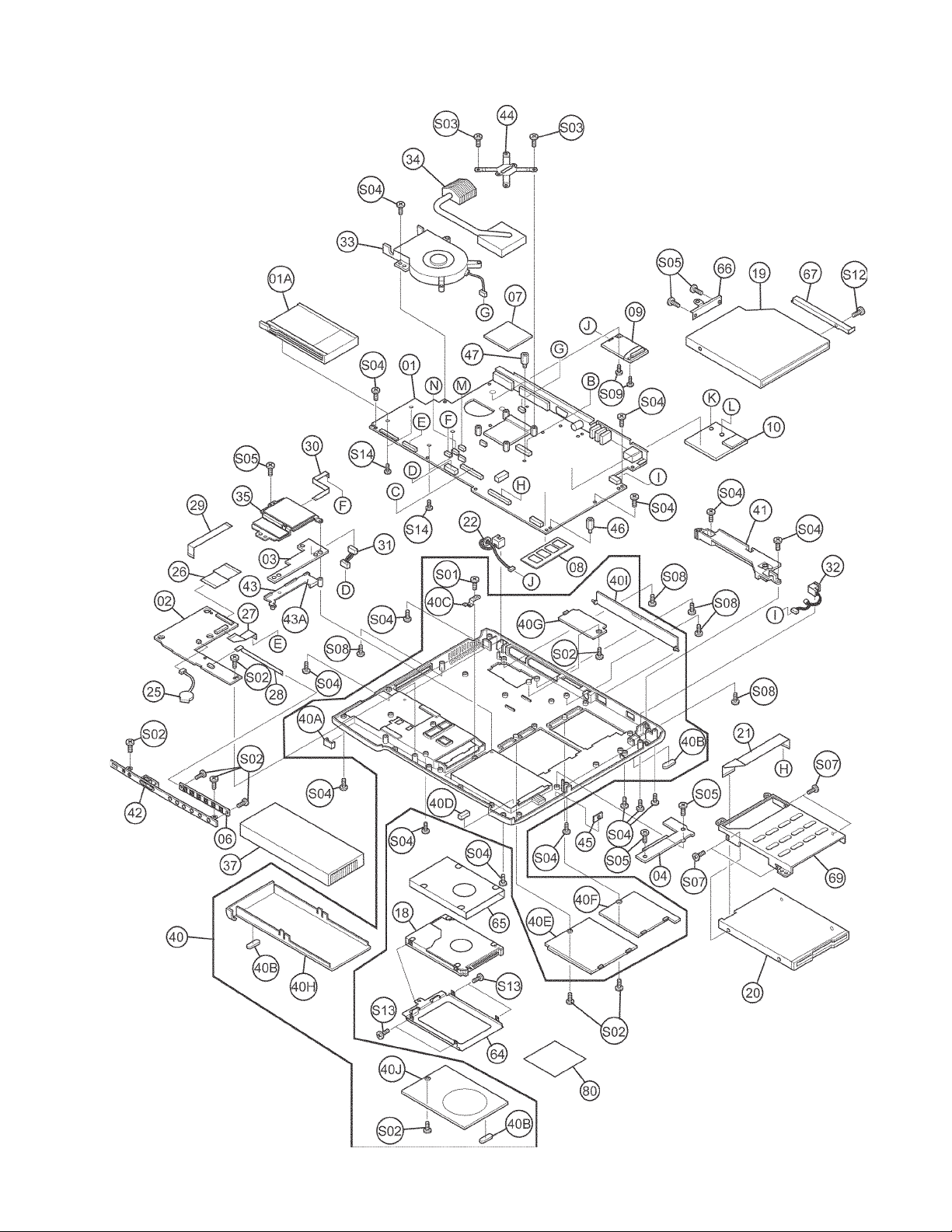
Satellite 1400 Series Exploded Lower View
Toshiba TRR Page 3 7/02, Satellite

Satellite 1400 Series Part Numbers
Ref. # Code Part # Description PIR Comments
C1Y2 PS140U-027XF3 1400-S152/30 (027XF3)
C1Y2 PS140U-027XF3B
C1Y2 PS140U-027XF7 1400-S151/30 (027XF7)
C1Y2 PS140U-027XF7B
C1Y2 PS140U-027XF7W 1400-S151/30 (027XF7W)
C1Y2 PS140U-027XF7WB
C1Y2 PS140U-027XF7X 1400-S151/30 (027XF7X)
C1Y2 PS140U-027XF7XB
C1Y2 PS140U-027XFJ 1405-S152/30 (027XFJ)
C1Y2 PS140U-027XFJB
C1Y2 PS140U-027XFX 1405-S151/30 (027XFX)
C1Y2 PS140U-027XFXB
C1Y3 PS140U-027XFNNC
C1Y3 PS140U-027XFPNC
C1Y4 PS140U-027W57
C1Y4 PS140U-027W57B
C1Y5 PS140U-027W5701
C1Y6 PS140U-027W5702
OP01 C1Y5 KTT-SO133/128 MEM MODULE, 128MB Kingston 128MB PC133 SDRAM Memory Module
OP01-A C1Y2 KTT-SO133/256 MEM MODULE, 256MB Kingston 256MB PC133 SDRAM Memory Module
OP02 C1Y3 PA3083U-1ACA UNIV AC ADAPTER Input:100V-240V, 1.2A-0.6A, 50-60Hz, Output:15VDC, 5A, 75 watt,(U,C,Z)
OP02A C1Y2 P000337890 AC ADAPTER Input: 100V-240V, 1.2A-0.6A, 50-60Hz, Output: 15VDC, 5A (UA2042P02)
OP02B C1Y2 P000327770 AC CORD SET (U, C, Z)
OP03 C1Y2 PA3107U-1BRS BATTERY PACK Lithium-Ion 10.8VDC, 4500mAh, with Recycle Label, (U,E)
OP03A C1Y2 P000324210 BATTERY PACK CEH Lithium-Ion 10.8VDC, 4500mAh, with Recycle Label, XM2033P02, (U,E)
OP03A-1 C1Y4 P000337840 BATTERY PACK CEH Lithium-Ion 10.8VDC, 4500mAh, with Recycle Label, XM2040P02 (U E,Z)
OP03A-2 C1Y5 P000350480 BATTERY PACK CEH Lithium-Ion 10.8VDC, 4500mAh, with Recycle Label (U,E,Z)
OP04 C1Y2 PA2488U BATT CHARGER (MAIN) For Main Battery Pack
OP05 C1Y2 PA3212U-1MPC
OP05A C1Y6 P000339520 WIRELESS LAN CARD Agere Systems MPCI3A-20/R, ZA2314P04
S01 C1Y6 P000300290 T SCREW, M2.5X6
S02 C1Y3 P000318000 TG SCREW, M2.5X4BN Black, Flat-Head (low profile) screw
S03 C1Y6 P000207940 SCREW, M2X6
S04 C1Y2 P000317990 TG SCREW, M2.5X6BN
S05 C1Y2 P000274010 T GRIP SCREW, M2X5C
S06 C1Y2 P000290500 GRIP SCREW, M2.5X16Z Black Grip Screw
S07 C1Y4 P000227770 SCREW, M2.5X2.6BN Black, Flat-Head (low profile) screw
S08 C1Y2 P000322980 GRIP SCREW, M2.5X25BN
S09 C1Y2 P000273730 T GRIP SCREW, M2X4Z Zinc (gold) flat-head (low profile head) screws
S10 C1Y2 P000239510 GRIP SCREW, M2.5X5Z
S11 C1Y3 P000315550 TG SCREW, M2.5X2.8B
S12 C1Y2 P000273850 T GRIP SCREW, M2X3C Silver, Flat-Head (low profile) screw
S13 C1Y4 P000339380 THIN SCREW, M3X4Z Silver, Flat-Head (low profile) screw
S14 C1Y4 P000261770 GRIP SCREW, M2X12Z
1 C1Y2 P000348950 PCB ASSY FRTSA2 System Board, without CPU, without memory, A5A000255010
1A C1Y2 P000323270 CARDBUS CONNCTOR PC Card Connector, G36220279179
2 C1Y3 P000348960 PCB ASSY FRTSD1 Sound Board, A5A000233030
3 C1Y2 P000347340 PCB ASSY FRTBA1 Battery (Battery Terrminal) Board, G70C00004210
4 C1Y2 P000347350 PCB ASSY FRTHD1 HDD Connector Board (contains W-LAN switch), G70C00005210
5 C1Y2 P000347360 PCB ASSY FRTPW1 Power Switch Board, G70C00006210
6 C1Y2 P000347370 PCB ASSY FRTCW1 CD Switch Board, G70C00007210
7 C1Y2 P000348650 IC RH80530NZ009 Intel 1.20GHz Cel, apply grease to CPU before mounting Cooling Mod
8-A C1Y5 P000328480 256MB SO DIMM Approved makes = Toshiba; SME - Samsung, ELP - Elpida; HYS - Hyundia
9 C1Y2 P000322090 MDC MODEM Modem Daughter Card, Askey Computer 1456VQL4 (INT), ZA2300P06
10 C1Y5 P000339520 WIRELESS LAN CARD Agere Systems MPCI3A-20/R, ZA2314P04
11 C1Y4 P000332290 COLOR LCD MODULE Chimei N141X6-02, 14.1 XGA TFT, VF2093P01
11A C1Y3 P000334580 FL TUBE SET
12 C1Y2 P000309120 COLOR LCD MODULE Samsung LTN141X7-L06, 14.1XGA TFT, VF2048P01
12A C1Y2 P000310980 FL TUBE
12B C1Y4 P000310990 AL TAPE
12C C1Y2 P000311000 WIRE TAPE
12D C1Y2 P000311010 SCREW, M2X1.7
12E C1Y4 P000311020 SCREW, M2X2.5
12F C1Y2 P000311030 PCB COVER
12G C1Y2 P000311040 LAMP COVER
12H C1Y3 P000311050 CLIP
13 C1Y2 P000316700 COLOR LCD MODULE LG Philips LP141X7-C1TO,14.1 XGA TFT, VF2062P01"
13A C1Y2 P000318970 FL LAMP KIT
14 C1Y4 P000309110 COLOR LCD MODULE Toshiba LTM14C433, 14.1 XGA TFT, VF2047P01"
14A C1Y4 P000311060 FL TUBE SET
15 C1Y2 P000338370 COLOR LCD MODULE Toshiba LTM14C501, 14.1 XGA TFT, VF2096P01"
1400-S152 (027XF3B) B-STK
1400-S151 (027XF7B) B-STK
1400-S151 (027XF7WB)B-STK
1400-S151 (027XF7X)B-STK
1405-S152 (027XFJB) B-STK
1405-S151 (027XFXB) B-STK
1405-S151/30 (027XFNNC)
1400-S151/30 (027XFPNC)
1400-S151W/30 (027W57) S1400-S151W/30, WXP Pro, 1.20GHz Cel, 256MB, CD-RW/DVD, 14 TFT, Modem/LAN, Wi-Fi LAN
1400-S151W (027W57B)B-STK S1400-S151W/30, WXP Pro, 1.20GHz Cel, 256MB, CD-RW/DVD, 14 TFT, Modem/LAN, Wi-Fi LAN, Remf
1400-S151W/30 (027W5701)
1400-S151W/30 (027W5702)
WIRELESS LAN CARD KIT
S1400-S152/30, WXP Home, 1.20GHz Cel, 256MB, CD-RW/DVD, 14 TFT, Modem/LAN, (W’less Ready)
S1400-S152/30, WXP Home, 1.20GHz Cel, 256MB, CD-RW/DVD, 14 TFT, Modem/LAN, (W’less Ready), Remf
S1400-S151/30, WXP Pro, 1.20GHz Cel, 256MB, CD-RW/DVD, 14 TFT, Modem/LAN, (W’less Ready)
S1400-S151/30, WXP Pro, 1.20GHz Cel, 256MB, CD-RW/DVD, 14 TFT, Modem/LAN, (W’less Ready), Remf
S1400-S151/30, WXP Pro, 1.20GHz Cel, 256MB, CD-RW/DVD, 14 TFT, Modem/LAN, (Office XP SB), (W’less Ready)
S1400-S151/30, WXP Pro,1.20GHz Cel,256MB,CD-RW/DVD,14 TFT,Modem/LAN,(Office XP SB),(W’less Ready),Remf
S1400-S151/30, WXP Pro, 1.20GHz Cel, 256MB, CD-RW/DVD, 14 TFT,Modem/LAN,(Office XP Pro),(W’less Ready)
S1400-S151/30,WXP Pro,1.20GHz Cel,256MB,CD-RW/DVD,14 TFT,Modem/LAN,(Office XP Pro),(W’less Ready),Remf
S1405-S152/30, WXP Pro, 1.20GHz Cel, 256MB, CD-RW/DVD, 14 TFT, Modem/LAN, (W’less Ready)
S1405-S152/30, WXP Pro, 1.20GHz Cel, 256MB, CD-RW/DVD, 14 TFT, Modem/LAN, (W’less Ready), Remf
S1405-S151/30, WXP Home, 1.20GHz Cel, 256MB, CD-RW/DVD, 14 TFT, Modem/LAN, (W’less Ready)
S1405-S151/30, WXP Home, 1.20GHz Cel, 256MB, CD-RW/DVD, 14 TFT, Modem/LAN, (W’less Ready), Remf
S1405-S151/30, WXP Home, 1.20GHz Cel, 256MB, CD-RW/DVD, 14 TFT, Modem/LAN, (W’less Ready), Sp
S1400-S151/30, WXP Pro, 1.20GHz Cel, 256MB, CD-RW/DVD, 14 TFT, Modem/LAN, (W’less Ready), Sp
S1400-S151W/30, WXP Pro, 1.20GHz Cel, 256MB, CD-RW/DVD, 14 TFT, Modem/LAN, Wi-Fi LAN, (NFS)
S1400-S151W/30, WXP Pro, 1.20GHz Cel, 256MB, CD-RW/DVD, 14 TFT, Modem/LAN, Wi-Fi LAN, (NFS)
7/02, SatelliteToshiba TRR Page 4

Satellite 1400 Series Part Numbers, (cont.)
Ref. # Code Part # Description PIR Comments
15A C1Y2 P000338550 FL TUBE SET
16 C1Y2 P000348970 COLOR LCD MODULE Sharp LQ141X1LH83, 14.1 XGA TFT, VF2065P02"
16A C1Y2 P000350800 FL TUBE
16B C1Y2 P000261140 SCREW, M2X2
16C C1Y2 P000350810 COVER S
16D C1Y2 P000316210 AL TAPE
16E C1Y4 P000350820 TAPE
17 C1Y5 P000347420 FL INVERTER
18-A C1Y2 P000341840 HDD UNIT (30GB) Toshiba, MK30KEF, HDD2169B
18-A-1 C1Y4 P000341850 HDD UNIT (30GB) CEH IBM IC25N030ATCS04 (ATD04T), P/N: 07N8326, 07N9318, G8BC00004210
18-A-2 C1Y2 P000343820 HDD UNIT (30GB) CEH Hitachi DK23DA-30F, G8BC00006210
19-A C1Y2 P000349540 CD-RW/DVD-ROM Toshiba SD-R2102-OAHB, G8CC00009210
19-A-1 C1Y2 P000347430 CD-RW/DVD-ROM CEH Panasonic (KME - Kyushu Matsushita Electric) UJDA720, ZA2431P02
20 C1Y2 P000347440 FDD UNIT Teac FD05HG-7778, G8AC00002210, requires P000347760
20-1 C1Y2 P000349920 FDD UNIT CEH Samsung SFD-321S/TB1 G8AC00007110, requires P000347760
20-A C1Y2 P000347450 FDD UNIT Mitsumi D353F3X/R-3220, G8AC00003110, requires P000349670
21 C1Y3 P000347760 1.0MM PITCH FFC FDD Cable for Teac or Samsung FDD
21-A C1Y2 P000349670 1.0MM PITCH FFC CDA FDD Cable for Mitsumi FDD
22 C1Y2 P000347460 RJ11 HARNESS
23 C1Y2 P000220300 MODULAR CABLE Modem Cable
24 C1Y2 P000322640 AC ADAPTER Input:100V-240V 1.5A-0.85A, 50-60HZ; Output: 15V 4A, PA3092U—1ACA
25 C1Y2 P000331520 RTC BATTERY Lithium Ion, 3.6V, 15mAh
26 C1Y2 P000347480 0.5MM PITCH FFC Cable between Sound Board and System Board
27 C1Y4 P000347490 0.5MM PITCH FFC Cable between Sound Board and System Board
28 C1Y3 P000347500 0.5MM PITCH FFC Cable between Sound Board and CD Switch Board
29 C1Y4 P000347510 0.5MM PITCH FFC
30 C1Y3 P000347520 0.5MM PITCH FFC Cable between Touch Pad and System Board
31 C1Y2 P000347530 BATTERY HARNESS Cable between Battery Board and System Board
32 C1Y2 P000347540 DC JACK HARNESS DC-In Cable
33 C1Y2 P000347550 DC FAN Cooling Fan Module, apply grease to CPU before installing Cooling Mod.
34 C1Y3 P000347560 FIN Heatsink unit, apply grease to chip before installing
35 C1Y2 P000348990 TOUCH PAD
36 C1Y4 (RESERVED)
37 C1Y4 P000337840 BATTERY PACK Lithium-Ion 10.8VDC, 4500mAh, with Recycle Label, XM2040P02 (U E,Z)
37-1 C1Y2 P000350480 BATTERY PACK CEH Lithium-Ion 10.8VDC, 4500mAh, with Recycle Label (U,E,Z)
38 C1Y6 P000347580 KEYBOARD UNIT Minebea WLJ-5508W, G83C0000E210, (U)
38-A C1Y3 UE2024P36KB-SP KEYBOARD UNIT, SP For Latin America, Alps Electric KFRMBA059A, UE2024P36
39 C1Y6 P000327770 AC CORD SET (U, C, Z)
40 C1Y2 P000347590 BASE ASSY For units with letter C stamped on Base in battery compartment area
40-A C1Y2 P000348470 BASE ASSY For units with letter D stamped on Base in battery compartment area
40-B C1Y6 P000349710 BASE ASSY For units with letter P stamped on Base in battery compartment area
40A C1Y2 P000347970 FIR COVER For units with letter C stamped on Base in battery compartment area
40A-A C1Y2 P000348530 FIR COVER For units with letter D stamped on Base in battery compartment area
40A-B C1Y2 P000349770 FIR COVER For units with letter P stamped on Base in battery compartment area
40B C1Y3 P000347980 BOTTOM CUSHION
40C C1Y4 P000347990 HDD BRACKET
40D C1Y2 P000222130 GUM CUSHION
40E C1Y4 P000348000 MEMORY COVER ASSY For units with letter C stamped on Base in battery compartment area
40E-A C1Y2 P000348540 MEMORY COVER ASSY For units with letter D stamped on Base in battery compartment area
40E-B C1Y2 P000349780 MEMORY COVER ASSY For units with letter P stamped on Base in battery compartment area
40F C1Y2 P000348010 MINI PCI COVER For units with letter C stamped on Base in battery compartment area
40F-A C1Y2 P000348550 MINI PCI COVER For units with letter D stamped on Base in battery compartment area
40F-B C1Y2 P000349790 MINI PCI COVER For units with letter P stamped on Base in battery compartment area
40G C1Y2 P000348020 MDC COVER Modem Slot Cover, For units with letter C stamped on Base
40G-A C1Y2 P000348560 MDC COVER Modem Slot Cover, For units with letter D stamped on Base
40G-B C1Y2 P000349800 MDC COVER Modem Slot Cover, For units with letter P stamped on Base
40H C1Y2 P000348030 BATT COVER ASSY For units with letter C stamped on Base in battery compartment area
40H-A C1Y2 P000348570 BATT COVER ASSY For units with letter D stamped on Base in battery compartment area
40H-B C1Y2 P000349810 BATT COVER ASSY For units with letter P stamped on Base in battery compartment area
40I C1Y2 P000348040 REAR CONN. COVER For units with letter C stamped on Base in battery compartment area
40I-A C1Y4 P000348580 REAR CONN. COVER For units with letter D stamped on Base in battery compartment area
40I-B C1Y4 P000349820 REAR CONN. COVER For units with letter P stamped on Base in battery compartment area
40J C1Y5 P000348050 HDD COVER ASSY For units with letter C stamped on Base in battery compartment area
40J-A C1Y5 P000348590 HDD COVER ASSY For units with letter D stamped on Base in battery compartment area
40J-B C1Y2 P000349830 HDD COVER ASSY For units with letter P stamped on Base in battery compartment area
41 C1Y2 P000347600 CONN. HOLDER ASSY Plastic Brace
42 C1Y2 P000347610 FRONT COVER ASSY For units with letter C stamped on Base in battery compartment area
42-A C1Y2 P000348480 FRONT COVER ASSY For units with letter D stamped on Base in battery compartment area
42-B C1Y2 P000349720 FRONT COVER ASSY For units with letter P stamped on Base in battery compartment area
43 C1Y4 P000347620 BATT CONN. COVER
43A C1Y3 P000343570 SPRING, BATT SAFETY
Toshiba TRR Page 5 7/02, Satellite

Satellite 1400 Series Part Numbers, (cont.)
Ref. # Code Part # Description PIR Comments
44 C1Y2 P000347630 CPU HOLDER
45 C1Y2 P000347640 W'LESS LAN SW. KNOB For units with letter C stamped on Base in battery compartment area
45-A C1Y4 P000348490 W'LESS LAN SW. KNOB For units with letter D stamped on Base in battery compartment area
45-B C1Y2 P000349730 W'LESS LAN SW. KNOB For units with letter P stamped on Base in battery compartment area
46 C1Y2 P000283510 CPU STUD M2.5X6 Stud Screw
47 C1Y2 P000309450 HEXA STUD M2.5X14 Stud Screw
48-49 C1Y3 (RESERVED)
50 C1Y3 P000349010 COVER ASSY For units with letter C stamped on Base in battery compartment area
50-A C1Y2 P000349090 COVER ASSY For units with letter D stamped on Base in battery compartment area
50-B C1Y2 P000350000 COVER ASSY For units with letter P stamped on Base in battery compartment area
50A C1Y2 P000349030 COVER SUB ASSY For units with letter C stamped on Base in battery compartment area
50A-A C1Y2 P000349110 COVER SUB ASSY For units with letter D stamped on Base in battery compartment area
50A-B C1Y2 P000350010 COVER SUB ASSY For units with letter P stamped on Base in battery compartment area
50AA C1Y2 P000347790 LCD CUSHION
50AB C1Y5 P000349040 TOUCH PAD BUTTON For units with letter C stamped on Base in battery compartment area
50AB-A C1Y6 P000349120 TOUCH PAD BUTTON For units with letter D stamped on Base in battery compartment area
50AB-B C1Y5 P000350020 TOUCH PAD BUTTON For units with letter P stamped on Base in battery compartment area
50B C1Y2 P000349050 LCD COVER ASSY For units with letter C stamped on Base in battery compartment area
50B-A C1Y2 P000349130 LCD COVER ASSY For units with letter D stamped on Base in battery compartment area
50B-B C1Y2 P000349860 LCD COVER ASSY For units with letter P stamped on Base in battery compartment area
50BA C1Y2 P000347820 LCD LATCH HOOK For units with letter C stamped on Base in battery compartment area
50BA-A C1Y2 P000348630 LCD LATCH HOOK For units with letter D stamped on Base in battery compartment area
50BA-B C1Y2 P000349870 LCD LATCH HOOK For units with letter P stamped on Base in battery compartment area
50BB C1Y2 P000347830 SENSOR SW. MAGNET
50BC C1Y2 P000347840 D STICK TAPE
50C C1Y2 P000349060 BRAKE HINGE, RIGHT
50D C1Y4 P000349070 BRAKE HINGE, LEFT
50E C1Y6 P000347870 BH UPPER INSULATOR Brake Hinge Upper Insulator
50F C1Y2 P000347880 SPEAKER, LEFT
50G C1Y2 P000347890 SPEAKER, RIGHT
50H C1Y2 P000347900 ANTENNA CABLE Wireless LAN Antenna
50I C1Y2 P000350190 LCD HARNESS LCD/FL Cable
50J C1Y2 P000347920 CABLE HOLDER For units with letter C stamped on Base in battery compartment area
50J-A C1Y6 P000348640 CABLE HOLDER For units with letter D stamped on Base in battery compartment area
50J-B C1Y2 P000349880 CABLE HOLDER For units with letter P stamped on Base in battery compartment area
50K C1Y2 P000347930 CABLE EARTH PLATE
50L C1Y4 P000347940 HARNESS HOLDER
50M C1Y6 P000347950 CUSHION TAPE
50N C1Y4 P000347960 TOSHIBA BADGE for Display Cover
51 C1Y2 P000349020 LCD MASK ASSY For units with letter C stamped on Base in battery compartment area
51-A C1Y2 P000349100 LCD MASK ASSY For units with letter D stamped on Base in battery compartment area
51-B C1Y4 P000349750 LCD MASK ASSY For units with letter P stamped on Base in battery compartment area
51A C1Y3 P000312850 LCD CUSHION
51B C1Y3 P000322780 TOSHIBA BADGE For Display Mask
51C C1Y2 P000322790 LCD GUM CUSHION
52 C1Y2 P000347670 SCREW SEAL
53 C1Y2 P000333940 LCD MASK SEAL
54 C1Y2 P000349960 LCD SUPPORT 14, L.
55 C1Y5 P000349970 LCD SUPPORT 14, R.
56 C1Y2 P000347690 KEYBD HOLDER ASSY Keyboard Brace, For units with letter C stamped on Base
56-A C1Y3 P000348520 KEYBD HOLDER ASSY Keyboard Brace, For units with letter D stamped on Base
56-B C1Y2 P000349760 KEYBD HOLDER ASSY Keyboard Brace, For units with letter P stamped on Base
57 C1Y4 P000347700 PRODUCT BADGE
58-59 C1Y2 (RESERVED)
60 C1Y5 P000347710 SUPPORT PLATE Metal Plate
61 C1Y2 P000347720 KEYBD HOLDER PLATE
62-63 C1Y2 (RESERVED)
64 C1Y4 P000347730 HDD HOLDER ASSY HDD Bracket
65 C1Y2 P000316400 HDD INSULATOR
66 C1Y5 P000347740 ODD REAR BRACKET Optical Disk Drive Rear Bracket
67 C1Y6 P000347750 ODD SIDE BRACKET Optical Disk Drive Side Bracket
68 C1Y3 (RESERVED)
69 C1Y2 P000347770 FDD BRACKET ASSY
70 C1Y2 (RESERVED)
71 C1Y3 P000316910 CHINA LABEL
72 C1Y3 P000319730 LITHUANIA LABEL
73 C1Y4 P000320520 CARD LABEL
74-79 C1Y2 (RESERVED)
210 C1Y5 597890 EXT. MICROPHONE Custom hardware - not used in all models
215 C1Y6 TOSH4 BAG ACCESSORY Carrying Case
7/02, SatelliteToshiba TRR Page 6

Satellite 1400 Series Disassembly Overview
The information offered in this section is an overview of the Maintenance Manual, Chapter 4, Replacement
Procedures. If you have any questions or concerns regarding the proper procedure please refer to the Maintenance Manual through the Toshiba Service and Support Website
before
you proceed.
This section explains how to remove Field
Replaceable Units (FRUs). It may not be necessary to remove all the FRUs in order to replace
one.
The chart is a guide to which FRUs need to be
removed in order to remove others. The section
numbers on the chart refer to the sections in the
Maintenance Manual, Chapter 4.
Always start by removing the battery pack, next,
optional items such as the optional PC card and
optional memory module, then follow the line on
the chart to determine which FRU you must
remove next in order to repair the one you think is
causing the computer to operate improperly.
To remove the battery, follow the steps below.
CAUTION: When handling battery packs, be
careful not to short circuit the terminals. Also
do not drop, hit or otherwise apply impact; do
not scratch or break the casing.
1. Turn the computer upside down.
2. Slide the battery latch to the left to
release it, then pull the battery cover
slightly forward and lift it out.
3. Lay the battery cover upside down. Push
the latches to the outside and lift out the
battery pack.
NOTE: For environmental reasons, do not
throw away a spent battery pack. Please follow
local ordinances or regulations for its disposal.
To remove an optional PC card, follow the steps
below.
1. Turn the computer right side up.
2. Press the eject button for the PC card
you want to remove, it will extend slightly.
3. Press the button again.
4. Grasp the PC card and remove it.
Toshiba TRR Page 7 7/02, Satellite

Satellite 1400 Series Disassembly Overview, cont.
To remove an optional SD card, follow the steps
below.
1. Turn the computer right side up.
2. Push the SD card in and release it to pop
the card out slightly.
3. Grasp the SD card and remove it.
To remove the HDD, follow the steps below.
1. Turn the computer upside down.
2. Remove one M2.5x4 black flat-head
screw securing the HDD cover.
3. Lift off the HDD cover.
4. Pull the guide to remove the HDD. Be
careful not to damage the connector.
5. Place the HDD pack on a flat surface and
remove four M2x4 silver flat-head
screws.
6. Remove the HDD bracket.
CAUTION: Do not apply pressure to the top or
bottom of the HDD.
To remove a memory module, follow the steps
below.
1. Turn the computer upside down.
2. Remove one M2.5x4 black flat-head
screw.
3. Lift off the memory slot cover.
4. Gently press out on two latches. One
end of the memory module will pop up.
5. Grasp the memory module and remove
it.
CAUTION: Do not try to remove a memory
module with the computer turned on. You can
damage the computer and the memory.
Do not touch the connectors on the memory
module(s) or on the computer. Debris on the
connectors may cause memory access problems.
7/02, SatelliteToshiba TRR Page 8

Satellite 1400 Series Disassembly Overview, cont.
To remove the modem daughter card (MDC), follow
the steps below.
1. Turn the computer upside down.
2. Remove one M2.5x4 black flat-head
screw.
3. Lift off the modem slot cover.
4. Remove two M2x4 super flat screws
securing the MDC.
5. Carefully lift up the MDC to disconnect it
from PJ9 (S1400) or PJ125 (S2400) on
the system board.
6. Carefully disconnect the modem cable
from JP1 on the MDC.
To remove the wireless LAN card, follow the steps
below.
1. Remove one M2.5x4 black flat-head
screw.
2. Lift off the Wireless LAN card slot cover.
3. Disconnect the Wireless LAN antenna
cables (black and white) from the
Wireless LAN card using an antenna
coaxial cable disconnector.
4. Push the Wireless LAN card lock
latches outward to release the card. It
will pop up to about a 45 degree angle.
5. Pull out the Wireless LAN card. Be
careful not to damage the connector.
To install the wireless LAN card (an option in some
models), follow the steps below.
CAUTION: Be sure to turn the computer off before
removing the card. Otherwise, the computer or the
card may be damaged.
1. Insert the Wireless LAN card into the
connector at an angle of 45 degrees.
2. Gently push the Wireless LAN card down
until latches on both sides engage to
hold it in place.
3. Connect the Wireless LAN antenna
(black and white) cables to the
connectors on the card.
CAUTION: Be sure the cables lie inside the guide.
Be careful not to damage or pinch the cables
when you seat the card.
4. Seat the Wireless LAN card slot cover.
5. Secure the cover with one M2.5x4 black
flat-head screw.
CAUTION: There are two MAC address barcode
labels in the package with the card. Apply one
labelo next to the Wireless LAN socket and one
on the box the computer was shipped in. Remove
old labels before applying the new ones. The
computer may have MAC address barcod labels
both wired and Wireless LANs. Be sure to replace
the correct label.
Toshiba TRR Page 9 7/02, Satellite

Satellite 1400 Series Disassembly Overview, cont.
"
#
To remove the keyboard, follow the steps below.
1. Open the display panel.
2. Insert the fingernails of both hands into
notches in the keyboard brace and the
computer, and pry up to release the
brace at twelve points. Remove the
brace.
3. Remove one M2.5x4 black flat-head
screw securing the metal brace.
4. Remove two M2.5x2.6 black flat-head
screws.
5. Rotate the keyboard out and lay it on top
of the palmrest.
6. Disconnect the keyboard cable from
PJ2003 on the system board and remove
the keyboard.
To remove the power switch board, follow the steps
below.
1. Disconnect the SUMI card from PJ2018.
2. Remove one M2.5x4 black flat-head
screw.
3. Remove the power switch board and
turn it over.
4. Disconnect the SUMI card from PJ7200.
!
To remove the top cover with display assembly,
follow the steps below.
1. Turn the computer upside down and
remove the following nineteen screws:
• Thirteen M2.5x6 black flat-head
• Six M2.5x5 black flat-head
2. Turn the computer right side up and open
the display panel.
3. Remove two M2.5x6 black screws and
two M2.5x16 black screws.
4. Remove the metal plate.
5. Disconnect the LCD/DL cable from
PJ5001 and the speaker cables from
PJ2020 and PJ2021 on the system
board.
6. Remove one M2x6 screw securing the
top cover.
7. Remove the top cover with display
assembly starting from the front. Be
careful not to damage the wireless LAN
antenna coaxial cables.
!
Images continued on the next page
7/02, SatelliteToshiba TRR Page 10

Satellite 1400 Series Disassembly Overview, cont.
"
"
#
!
!
To remove the optical disk drive, follow the steps
below.
1. Disconnect the optical disk drive (DVD)
from PJ2001 on the system board.
2. Carefully slide the drive to the right to
remove it.
3. Remove two M2x5 silver thin flat-head
screws and the short metal brace.
4. Remove one M2x3 silver thin flat-head
screw and the long metal brace.
To remove the FDD, follow the steps below.
1. Disconnect the FDD SUMI card from
PJ2007 on the system board.
2. Lift out the FDD.
3. Remove four M2.5x2.6 screws securing
the metal case to the FDD and remove
the metal case.
4. Disconnect the FDD DUMI card from the
connector of the FDD.
NOTE: Two types of SUMI cards are used; one
manufactured by TEAC and SAMSUNG, and the
other by MITSUMI.
Toshiba TRR Page 11 7/02, Satellite

Satellite 1400 Series Disassembly Overview, cont.
!
To remove the touch pad, follow the steps below.
1. Disconnect the touch pad SUMI card
from PJ2004 on the system board.
2. Remove one M2x5 silver thin flat-head
screw securing the touch pad.
3. LIft out the touch pad.
4. Disconnect the touch pad SUMI card
from CN1 on the touch pad.
To remove the battery board, follow the steps below.
1. Disconnect the battery cable from
PJ8810.
2. Lift out the battery board.
3. Disconnect the battery cable from
PJ8811 on the battery board, if necessary.
NOTE: On installation, be sure to route the
battery cable under the battery board to avoid
pinching the battery cable with the plastic cover.
!
To remove the HDD connector board, follow the
steps below.
1. Remove two M2x5 silver thin flat-head
screws securing the HDD connector
board.
2. Carefully lift up the HDD connector
board to disconnect it from PJ2000 on
the system board.
3. Lift out the HDD connector board.
7/02, SatelliteToshiba TRR Page 12

Satellite 1400 Series Disassembly Overview, cont.
To install the HDD connector board, follow the steps
below.
1. Seat the HDD connector board and
carefully connect it to PJ2000 on the
system board.
2. Secure the HDD connector board with
two M2x5 silver thin flat-head screws.
3. Lift out the HDD connector board.
CAUTION: Be careful not to damage or pinch the
FDD SUMI card when you seat the HDD connector board. Be sure the wireless LAN switch is in
the correct position.
To remove the RTC battery, follow the steps below.
1. Disconnect the RTC battery cable from
PJ9999 on the sound board.
2. Lift out the RTC battery.
To remove the sound board, follow the steps below.
1. Disconnect the sound SUMI card from
PJ7100 and PJ7101 on the sound board.
2. Disconnect the CD switch board SUMI
card from PJ7102 on the sound board.
3. Remove one M2.5x4 screw securing the
sound board.
4. Lift up the sound board.
To remove the CD switch board, follow the steps
below.
1. Remove four M2.5x4 black flat-head
screws securing the front cover
assembly.
2. Remove the front cover assembly.
3. Remove the CD SUMI card from PJ7300
on the CD switch board.
4. Remove two M2.5x4 black flat-head
screws securing the CD switch board.
5. Remove the CD switch board from the
front cover assembly.
!
Toshiba TRR Page 13 7/02, Satellite

Satellite 1400 Series Disassembly Overview, cont.
!
!
To remove the DC-IN cable, follow the steps below.
1. Remove two M2.5x6 black flat-head
screws securing the plastic brace.
2. Remove the plastic brace.
3. Disconnect the DC-IN cable from PJ8800
on the system board.
4. Remove the DC-IN cable.
To remove the cooling fan, follow the steps below.
1. Remove two M2x6 screws securing the
metal brace.
2. Remove the metal brace.
3. Disconnect the power cable from
PJ8770 (S2400) or PJ770 (S1400) on the
system board.
4. Remove one M2.5x4 black flat-head
screw securing the cooling fan module.
5. Remove the cooling fan module.
6. Remove the heat sink unit, if necessary.
!
"
To remove the system board, follow the steps
below.
1. Remove three M2.5x6 black flat-head
screws securing the system board.
2. Remove the following two stud screws:
• One M2.5x6
• One M2.5x14
3. Lift up the system board from the right
side and remove it with the RJ-45 jack.
7/02, SatelliteToshiba TRR Page 14

Satellite 1400 Series Disassembly Overview, cont.
!
To remove the PC card slot, follow the steps below.
1. Lay the system board right side up.
2. Remove four M2x12 screws securing
the PC card slot.
3. Lay the system board right side up.
4. Disconnect the PC card slot from
PJ3332.
!
!
To remove the speakers, follow the steps below.
1. Lay the top cover and display assembly
upside down.
2. Remove four M2.5x5 screws securing
the speakers.
3. Remove the tape securing the speaker
cables.
4. Free the speaker cables from their
guides.
5. Remove the speakers.
Toshiba TRR Page 15 7/02, Satellite

Satellite 1400 Series Disassembly Overview, cont.
!
To remove the CPU, follow the steps below.
1. Remove two M2.5x6 black screws and
two M2.5x16 black screws securing the
metal plate.
2. Remove the metal plate.
3. Remove two M2x6 screws securing the
metal brace and lift if out.
4. Lift up the heat pipe and lay it on the
insulator.
5. Turn the cam to the unlock position with
a flat-blade screwdriver to unlock the
CPU.
6. Lift up the CPU.
CAUTION: When you remove the CPU, wipe the
grease off the bottom of the heat sink, the bottom
of the cooling fan, and the top of the CPU.
"
#
"
To install the CPU, follow the steps below.
1. Make sure the cam is in the open
position.
2. Seat the CPU in the CPU socket. Be
sure the alignment is exact to avoid
damaging pins on the CPU.
3. Press the interposer gently with your
fingers and turn the cam on the CPU
socket to the lock position with a flatblade screwdriver to secure the CPU.
4. Apply new grease on the CPU.
5. Seat the heat pipe on the CPU. Be sure
the alignment is exact to avoid damaging
pins on the CPU.
6. Secure the metal brace with two M2x6
screws.
7. Seat the metal plate and secure it with
two M2.5x6 black screws and two
M2.5x16 black screws.
CAUTION: When you install the CPU, apply new
grease at the top of the chip. Be sure the bottom
of the heat pipe covers the top of the CPU.
7/02, SatelliteToshiba TRR Page 16

Satellite 1400 Series Disassembly Overview, cont.
!
To remove the display mask, follow the steps below.
1. Remove two mask seals at the bottom
corners of the display assembly.
2. Remove two M2.5x6 flat-head screws.
3. Release twenty-one latches on the
display mask as follows:
• Five on the bottom
• Five on each side
• Six on the top
To remove the FL inverter board, follow the steps
below.
1. Remove one M2x4 flat-head screw
securing the FL inverter board.
2. Rotate the FL inverter board out and
disconnect the FL cable from CN1 on the
FL inverter board.
3. Disconnect the HV cable from CN2 on
the FL inverter board.
4. Remove the FL inverter board.
To remove the LCD module, follow the steps below.
1. Remove four masking seals that cover
the screws.
2. Remove four M2x4 screws securing the
LCD module.
3. Carefully rotate the top of the LCD
module out to access the LCD/FL cable.
4. Remove the tape securing the LCD/FL
cable.
5. Disconnect the LCD/FL cable.
6. Remove the LCD module.
7. Remove four silver super flat-head
!
M2x3 screws securing two metal
braces.
!
Images continued on the next page
Toshiba TRR Page 17 7/02, Satellite

Satellite 1400 Series Disassembly Overview, cont.
" "
To remove the antenna coaxial cables, follow the
steps below.
1. Remove two M2.5x6 tapping screws
securing the metal plate.
2. Remove the metal plate and the plastic
brace.
3. Slip tweezers into the side of the plastic
brace and pry to release two latches and
remove the bottom part of the plastic
brace.
4. Remove the tape securing the wireless
LAN antenna coaxial cables.
5. Free the wireless LAN antenna coaxial
cables from their guides and remove
them.
!
!
To remove the LCD/FL cable, follow the steps
below.
1. Remove two M2.5x6 tapping screws
securing the metal plate.
2. Remove the metal plate and the plastic
brace.
3. Remove one M2.5x6 tapping screw
securing the metal brace.
4. Remove the LCD/FL cable.
NOTE: When you remove the top cover, hold it by
the sides close to the hinges to prevent damage.
"
7/02, SatelliteToshiba TRR Page 18

Satellite 1400 Series Interrupts / Memory Map
Interrupt Assignments
Interrupt Level Assigned to:
— NMI RAM Parity Error, I/O Channel Error
1 3 COM 2/4*
2 11 Reserved
* These I/O assignments are controlled by PnP OS or system setup as shown
below:
0 Timer
1 Keyboard
2 PIC 2 for level 8 to 15
4 COM 1/3*
5 LPT 2*, or Secondary IDE*
6 FDC
7 LPT 1/3*
8RTC
9 Modem 2nd IRQ*
10 Reserved
12 PS/2 Mouse
13 Math co-processor
14 Primary IDE*
15 CD-ROM (ATAPI)*
IRQ level 0 1 2 3 4 5 6 7 8 9 10 11 12 13 14 15
IDE $$$ $ $$$ %$
CD-ROM (ATAPI) $$$ $ $$$ $%
Serial Port %%$ $ $$$ $$
Modem 2nd IRQ $$%$ $
FIR $$$ $ $$$ $$
Parallel Port $$$$$ $$
PCI Bus $$$ $ $$$
%: Default setting, $: Possible setting
System Memory Map
Address range Space (Kbytes) Use
'00000000' to '0009FFFF' 640 Conventional memory
'000A0000' to '000BFFFF' 128 Video RAM
'000C0000' to '000CFFFF' 64 VGA BIOS-ROM
'000D0000' to '000EFFFF' 128 Not used (PCI/ISA)
'00F0000' to '000FFFFF' 64 System BIOS ROM (Shadow RAM)
'00100000' to '03FDFFFF' 64,384 System working memory
'03FE0000' to '03FEFFFF' 64 ACPI
'03FF0000' to '03FFFFFF' 64 DMI
'04000000' to '0FFFFFFF' 196,608 (MAX.) Optional working memory
'0A)000000' to 'FFFDFFFF' Memory expansion in expansion port
'100A0000' to '100FFFFF' 384 System Management RAM and etc
'FFFF0000' to 'FFFFFFFF' 1,024 BIOS-ROM (duplicated) and etc
Toshiba TRR Page 19 7/02, Satellite

Satellite 1400 Series Input/Output Port Assignments
Port Map
Port address Device/function Port address Device/function
'000' to '01F' 82C37: DMA C #1 '2F8' to '2FF' Serial Port* (COM 2)
'020' to '03F' 82C59: PIC #1 '300' to '30F' Not used
'040' to '05F' 82C54: PIT '310' to '32F' Not used
'060' to '06F' KBC / System Status '330' to '337' Not used
'070' to 07F' RTC / NMI Mask Register '338' to '36F' Not used
'080' to '09F' DMA Page Register '370' to '375' Not used
'0A0' to '0BF' 82C59: PIC #2 '376' to '377' Secondary IDE
'0C0' to '0DF' 82C37: DMA C #2 '378' to 37F' Parallel Port* (LPT1)
'0E0' to '0EF' Special Register '380' to '387' Not used
'0F0' to '0FF' Math Coprocessor '388' to '38B' Not used
'100' to '16F' Not used '38C' to '3AF' Not used
'170' to '177' Secondary IDE* '3B0' to '3BB' VGA
'178' to '1EF' Not Used '3BC' to '3BF' Parallel Port* (LPT3)
'1F0' to '1F7' Primary IDE* '3C0' to '3DF' VGA
'1F8' to '1FF' Not used '3E0' to '3E7' PC Card Contoller
'200' to'207' Not used '3E8' to '3EF' Serial Port* (COM3)
'208' to '21F' Not used '3F0' to '3F5' FDC
'220' to '233' Sound (SB Pro) '3F6' Primary IDE
'234' to '23F' Not used '3F7' FDC / Primary IDE
'240' to '253' Sound (SB Pro) '3F8" to '3FF' Serial Port (COM1)
'254' to '25F' Not used '400' to '47F'' Not used
'260' to '263' Sound (SB Pro) '480' to '49F' DMA Hi-Page Register
'264' to '26F' Not used '4A0' to '52F' Not used
'278' to '27F' Parallel Port* (LPT2) '530' to '537' Sound (WSS)
'280' to '293' Sound (SB Pro) '540' to '547' Sound (WSS)
'294' to '2E7' Not used '550' to '557' Sound (WSS)
'2E8' to '2EF' Serial Port (COM4) '560' to '567' Sound (WSS)
'2F0' to '2F7' Not used
* These port addresses can be specified by System Setup.
7/02, SatelliteToshiba TRR Page 20
 Loading...