

Toshiba nv Series, SA9A1 Instruction Manual
Unified Controller
6F8C1511
nv
Series
type2 SOE Function
Instruction Manual

Notes
(1)The technical information provided herein describes typical operations and applications of the product and does not
guarantee the intellectual property rights or other rights of Toshiba or third parties nor allows license of its use.
(2)No part or the whole of this document may be reproduced without prior consent.
(3)The information herein may be changed in the future without notice.
(4)All possible measures have been taken to prepare the information herein. If you have any question, comment, or find
any error, please contact us.
PROSEC, TOSLINE, TOSDIC, CIEMAC are trademarks or registered trademarks of Toshiba Corporation.
Microsoft, Windows are registered trademarks of Microsoft Corporation in the U.S. and other countries.
IBM is a registered trademark of International Business Machines Corporation.
Device Net is a registered trademark of Open DeviceNet Vendor Association Inc.
Safety Precautions
On the product and this instruction manual, important information for safe and correct use to
prevent danger to the user and other people as well as property damage is described.
Understand the following information (signs and symbols) before reading the text, and follow
the described items
Description of signs
Sign Description
DANGER
WARNING
CAUTION
*1: A serious injury indicates loss of sight, injury, burns (high/low temperature), electric shock,
broken bones, or intoxication that will have aftereffects and require hospitalization or long-term
hospital visits for healing.
*2: An injury indicates an injury, burn, or electric shock that does not need hospitalization or
long-term hospital visits for healing.
*3: A property damage indicates consequential damage in terms of breakage of properties or
materials.
Indicates that failure to avoid it will result in an immediate risk of death or
serious injury(*1).
Indicates that failure to avoid it will result in a risk of death or serious
injury(*1).
Indicates that failure to avoid it will result in a risk of light or medium
injury(*2) or only property damage(*3).
Description of symbols
Symbol Meaning
Prohibited
Mandatory
Warning
(Note) Descriptions of Prohibition, Mandatory Action, and Warning vary depending on the display on the
main unit.
Indicates “Prohibition” or “You must not do”.
Specific details are indicated near the symbol
Indicates “Mandatory Action” or “Do as indicated”.
Specific details are indicated near the symbol
Indicates Warning.
Specific details Specific details are indicated near the symbol
pictures and text.
with pictures and text.
with pictures and text.
with
Unified Controller nv series type2 SOE Function Instruction Manual
i
1. Safety Precautions on Installation
WARNING
Ground
Prohibited
Mandatory
Prohibited
Mandatory
Ground the device.
Otherwise, it may cause an electric shock
or fire.
Do not install, store, or use it in
the following environments.
・ A place with a lot of dust
・ A place with corrosive gases (SO
or flammable gases
・ A place with vibrations and shocks
exceeding the allowed values
・ A place with condensations due to rapid
temperature changes
・ A place with low or high temperature
outside of the installation condition
・ A place with high humidity outside of the
installation condition
・ A place with direct sunlight
・ A place near equipment generating
strong radio waves or magnetic fields
It may cause accidents.
Install the device in a place
where maintenance and
inspection can be done easily.
Otherwise, it may cause accidents.
Do not block the ventilation hole
or air inlet/outlet.
It may cause fire or failure due to overheat.
For installation and wiring of the
system, observe the installation
conditions and methods
described in this document.
CAUTION
, H2S)
2
Prohibited
Mandatory
Mandatory
Mandatory
Do not insert any foreign object
such as wasted lines into the
module or unit.
It may cause fire, failure, or malfunction.
Install the power module,
controller module, and I/O
module to the dedicated base
unit.
Otherwise, it may cause an electric shock,
injury, or failure.
Do not use it alone or for other purposes.
Install or remove the module,
base unit, and terminal block
while the power is off.
Otherwise, it may cause an electric shock,
malfunction, or failure.
When connecting the
connectors and cables or
installing the module to the base
unit, press them fully until they
clicks, and secure them with
screws tightly.
Insufficient tightening may cause failure or
malfunction due to vibrations.
ii
Otherwise, it may cause a fall, fire, failure,
or malfunction.
6F8C1511
2. Safety Precautions on Wiring
WARNING
Mandatory
Mandatory
Mandatory
Mandatory
Mandatory
Mandatory
Connect the cables while the
power is off.
Otherwise, it may cause an electric shock
or failure.
When wiring the module, use
crimp contacts with sheath, or
cover it with tape.
Otherwise, exposed conductors may
cause an electric shock.
Connect an external power
supply that matches the rating.
Otherwise, it may cause an explosion or
fire.
Wiring work must be done by
qualified experts.
Wrong wiring may cause a fire, electric
shock, or failure.
Install a fuse that matches the
current capacity to the external
circuit for overload protection of
the relay output module.
Otherwise, a load short-circuit may cause
an accident or damage to the machine.
When using the contact relay
used for relay output, check the
contact life.
If the contact life of the relay is expired, an
output error may occur due to a defective
contact, resulting in an accident or damage
to the machine.
Contact relays have a life due to wearing
of the contact. If the life is expired,
replace it with a new one.
Mandatory
CAUTION
Mandatory
Mandatory
Mandatory
Install the terminal block cover
securely to the terminal block.
Exposed conducting parts may cause an
electric shock.
Observe the tightening torque.
If it is too loose, it may come off.
If the tightening torque is out of specified
range, it may be broken off.
M3.5 screw: 0.8 to 1.2 N・m
M3 screw: 0.5 to 0.75 N・m
Install the battery before use.
If the RAM is operated without any battery,
memory data or programs may be lost,
causing an accident or damage to the
machine due to malfunction.
Replace the battery according to the
battery replacement cycle guideline.
Turn on the power in the
following order:
Turn on the power of the nv series, and
then turn on the I/O module supply
external power and external load
power.
If this order is not followed, it may cause
an accident or damage to the machine due
to malfunction.
Unified Controller nv series type2 SOE Function Instruction Manual
iii
Mandatory
For system safety, turn off the
load power before the power of
the nv series.
If this order is not followed, it may cause
an accident or damage to the machine.
Share the external power supply for the I/O
module with the load power supply
whenever possible. If this is not possible,
construct the system so that the external
power supply and load power supply are
turned off simultaneously.
Mandatory
Construct the emergency stop
circuit and interlock circuit
outside the nv series.
Otherwise, it may cause an injury accident
or damage to the machine if failure or
malfunction occurs in the nv series.
iv
6F8C1511
3. Safety Precautions on Daily Use
WARNING
No touch
Prohibited
Mandatory
Do not touch the terminals of
the module and unit during
energization.
It may cause an electric shock.
Do not modify, repair,
disassemble, or adjust the
device, module, or board.
It may cause an electric shock, fire, injury,
or failure.
Upon faulty operation or failure, contact
one of Toshiba's branch offices or service
agencies.
Before using, check that the
power capacity, frequency,
voltage, and regulation comply
with the device specifications.
If not, it may cause damage of the device,
or fire due to overheat, as well as not
obtaining the original performance of the
device.
Mandatory
Prohibited
When there is any smoke or
strange odor, turn off the power.
Otherwise, it may cause a fire or electric
shock.
Contact one of Toshiba's branch offices or
service agencies.
When the ambient or internal
temperature of the device rises
abnormally or failure occurs in
the device, do not use the
device.
Using it as it is may cause fire due to
overheat.
Turn off the power, and contact one of
Toshiba's service representatives.
Mandatory
Prohibited
When performing program
changes during operation,
forced output, run, or halt
operations, ensure safety.
Wrong operations or failure to ensure
safety may cause an accident or damage
to the machine.
Do not forcefully bend, pull, or
twist the power cord and cables.
It may cause breaks or heating.
CAUTION
No touch
Prohibited
Do not touch the card parts,
contacts, connectors, or
soldered surface in the module.
Ends of the lead wire of the parts may
cause an injury, or electrostatic breakdown
of the ICs or LSIs may occur, resulting in
failure.
Do not insert any metal into the
gaps of the device main body.
It may cause fire.
Unified Controller nv series type2 SOE Function Instruction Manual
v
4. Safety Precautions on Maintenance and Inspection
When replacing the power fuse
or alarm fuse of the device, turn
off the device.
Otherwise, it may cause an electric shock
or fire.
Replace fuses or batteries with
specified items.
Using anything other than specified may
cause a fire or failure.
Be extremely careful when
measuring the power supply
voltage at the power terminal
part of the module during an
inspection.
Mandatory
Prohibited
When installing or removing the
module, unit, terminal block, or
wiring cable, make sure that the
external power supply is off.
Otherwise, there will be live electric poles
on the back of the external terminal block
of the module, causing an electric shock.
Do not connect the battery in
reverse, charge, disassemble,
overheat it, throw it into fire, or
short-circuit it.
It may cause an explosion or fire.
WARNING
Mandatory
Mandatory
Mandatory
Mandatory
Mandatory
Prohibited
Replace the battery every 5
years.
If the battery is worn, the data or programs
saved in the controller module may be lost,
causing an accident or damage to the
machine due to malfunction.
Replace the shutdown capacitor
every 8 years.
If the shutdown capacitor is worn, the data
or programs saved in the controller module
may be lost, causing an accident or
damage to the machine due to
malfunction.
Do not drop, crush, or apply
strong shocks to the device,
module, or board.
Otherwise it will cause failure.
CAUTION
Mandatory
Prohibited
Otherwise, it may cause an electric shock.
Replace the battery for the
controller module every 4 years
(confirmation required) if the
annual average temperature is
30C or less, or every 2 years
(confirmation required) if it is
above 30C.
If the battery is worn, the data or programs
saved in the controller module may be lost
depending on the application, causing an
accident or damage to the machine due to
malfunction.
When replacing the module, do
not install the different type.
Otherwise, it may cause an accident or
damage to the machine due to
malfunction.
vi
6F8C1511
Mandatory
Mandatory
Before touching the device,
module, or board, touch a
grounded metal to discharge the
static electricity of your body.
Otherwise, it may cause malfunction or
failure due to static electricity.
Wipe off stain on the device,
module, or board with a soft
cloth.
For severe stain, use a wet cloth wrung
tightly.
Leaving them stained may cause wrong
decision or malfunction.
Mandatory
Prohibited
Place a board or module
removed from the unit or base
unit on a conductive mat or
conductive bag (used for a
backup board) on a grounded
table.
Otherwise, parts may be damaged due to
static electricity.
Do not use benzene or thinner
to remove stain on device,
module, or board.
It may cause deformation or discoloration
of the device panel, module, or board.
Unified Controller nv series type2 SOE Function Instruction Manual
vii
5. Safety Precautions on Transportation, Storage, and Disposal
Prohibited
Do not throw the lithium battery
into a fire.
The battery may explode.
WARNING
Mandatory
When dispose the product, it
treats as industrial waste and
follows the ordinances and
rules.
Otherwise, it may cause environmental
damage.
CAUTION
Mandatory
For transportation and storage
of the product, use a conductive
bag and packaging box.
Otherwise it will cause failure.
viii
6F8C1511
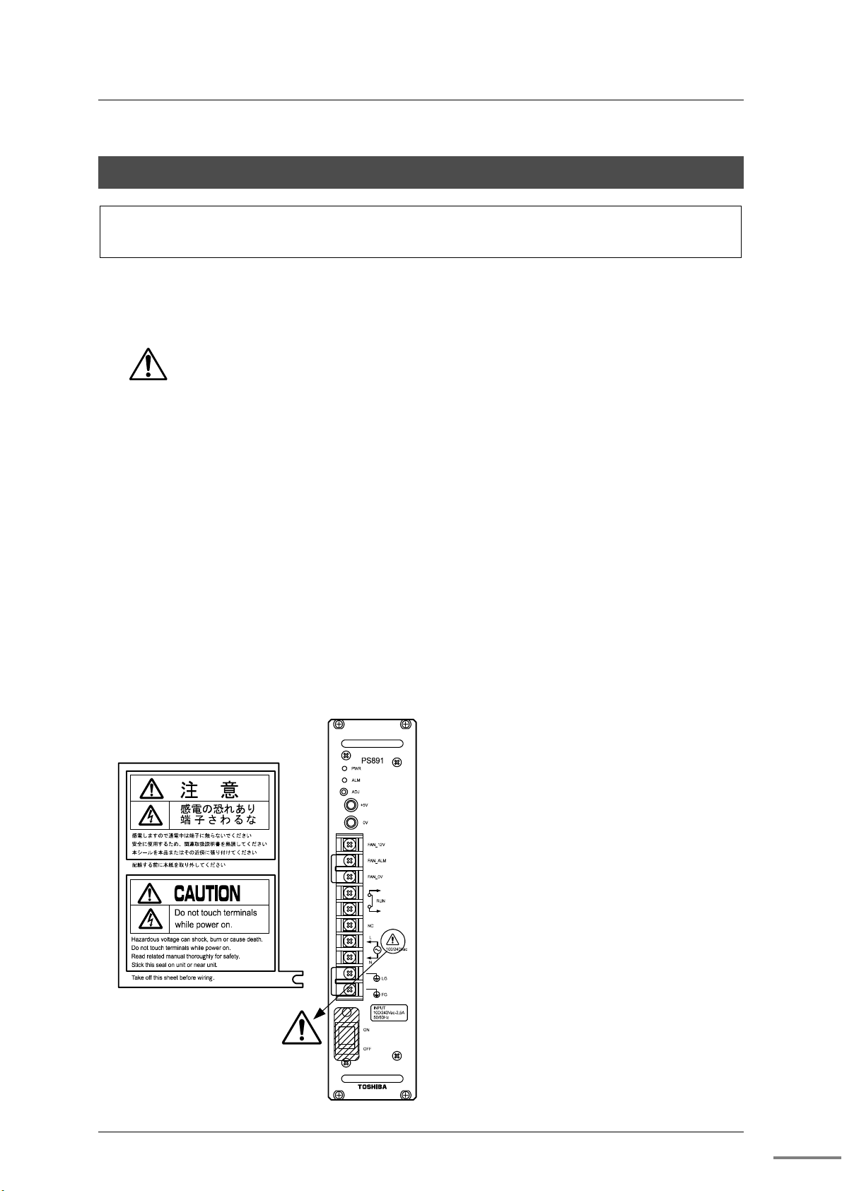
6. Checking the Warning Label on the Main Body
Check that warning label is attached on the main body.
If the label is missing or hard to read due to stain, contact our service department.
[Warning symbols on the nv series main body]
This symbol is a warning symbol for dangerous parts. It is attached on places
where there is a risk of an electric shock or a risk of damage to the main body due
to wrong wiring.
Note the following where this symbol is present.
● Touching the power input terminal of the power supply module while the power is on
causes an electric shock and is very dangerous.
Do not touch the power input terminal.
● For safety, turn off the power before wiring or performing maintenance and inspection.
● Wire the power input terminal correctly, and avoid applying any voltage exceeding the
specified voltage range. It may cause failure or damage.
● Perform connector connection of the nV-Tool port after turning off the power of the
nV-Tool (such as the PC).
Turn on the power of the nV-Tool after connection.
Be careful not to short-circuit the connector pins with the connector cover.
[Warning stickers]
The warning sticker as shown in the left
figure is attached to the power terminal of
the nv series (except for power supplies
below 24V).
Remove the sticker from the mount, and
attach it on the main body of the nv series,
or on a location near the nv series where it
can be seen easily.
There are stickers in both Japanese and
English. Use the one that suits your need.
When wiring, remove the sticker mount.
If the sticker is damaged, contact your
distributor.
Unified Controller nv series type2 SOE Function Instruction Manual
ix
Restrictions on Application
■
This product is not developed/manufactured for use in systems involving devices that
directly affect human life (Note 1). Do not use them for such applications.
■ To use this product for systems that involve devices that significantly affect human safety or
maintenance of public functions (Note 2), special considerations (Note 3) are required in
system operation, maintenance, and management. In this case, contact one of Toshiba's
sales representatives.
(Note 1) Devices that directly affect human life include the following.
Medical devices such as life supporting devices and devices for surgical units.
(Note 2) Systems that involve devices that significantly affect human safety or
maintenance of public functions include the following.
Main unit control systems of nuclear power plants, safety protection systems of
nuclear facilities, and other systems that are critical for safety
Operation control systems of mass transportation systems and air traffic control
systems
(Note 3) Special considerations indicate sufficient discussions with Toshiba's engineers to
construct a safe system (e.g. employing fool-proof design, fail-safe design, or
redundant design).
Disclaimer
Toshiba shall not be responsible for any damage caused by an earthquake, lightning and
■
wind, fire for which Toshiba is not responsible for, acts of a third party, other accidents, the
user's willful acts or negligence, misuse, or use in abnormal conditions.
■ Toshiba shall not be responsible for any incidental damage (loss of business profits,
interruption of business, change or loss of stored memory) caused by use of or unable to
use of this product.
■ Toshiba shall not be responsible for any damage caused by failure to observe the
information described in the operation manual.
■ Toshiba shall not be responsible for any damage caused by malfunctions due to combination
with any connected device.
■ Toshiba shall not be responsible for any damage caused by malfunctions due to combination
with any application program created by the customer.
6F8C1511
x

Precautions on Usage
Installation
●
Use your cellular phone or PHS one meter or more away from the product main unit in
operation, various transmission cables, and I/O cable. Otherwise, the system may cause
malfunction.
When connecting the connectors and cables or installing the module to the base unit,
secure them with screws tightly.
Insufficient tightening may cause failure or malfunction due to vibrations.
Power wiring
●
Keep the cables from other lines as much as possible. Especially, keep them away by
200mm or more from power lines.
The terminal screw size is M3.5. As applicable crimp contacts, use the one for 3.5M
screws whose width is 7mm or less.
Do not connect anything to the NC part.
Use of sample programs
●
Use the sample programs described in the operation manual after performing an operation
check.
Make sure to perform an operation check before actual operation to avoid an accident due
to malfunction.
Do not drop, bump, or apply strong shocks to the device or module. It may cause failure.
Battery replacement
●
Battery replacement can be done while the unit is energized or not energized. When
replacing the battery while the unit is not energized, complete the replacement within 3
minutes. If the unit is left without a battery for a long time, the content of the RAM
memory may be lost.
The Battery Normal LED (BAT) may illuminate during battery replacement. This is not an
error.
If the voltage decreases with the battery installed, the state will be detected normally and
the LED goes off.
The battery voltage is not compatible with manganese batteries or alkaline batteries. Do
not mix them.
Do not use a battery when 3 years or more have passed since the production date.
Maintenance
●
Place a module removed from the unit on a conductive mat or conductive bag (used for a
backup board) on a grounded table.
Otherwise, parts may be damaged due to static electricity.
Before touching the device or module, touch a grounded metal to discharge the static
electricity of your body. Otherwise, it may cause malfunction or failure due to static
electricity.
Wipe off stain on the device or module with a soft cloth.
For severe stain, use a wet cloth wrung tightly.
Leaving them stained may cause wrong decision or malfunction.
Do not use benzene or thinner to remove stain on device or module.
It may cause deformation or discoloration of the device panel or module.
To keep the system normal and avoid unnecessary troubles, perform daily inspections,
regular inspections, and cleaning.
Unified Controller nv series type2 SOE Function Instruction Manual
xi

Observe the following
●
To assure safety of the operator and normal operation of the device when the device is used,
observe the following.
1. Before installation, operation, maintenance, or inspection, read this operation manual
and all the related manuals thoroughly to obtain device information, safety information,
and other considerations. Use the device after reading the operation manual
thoroughly.
2. Do not install or store it in the following environments.
(1) A place with a lot of dust
(2) A place with corrosive gases (SO
(3) A place with vibrations and shocks
(4) A place with low or high temperature outside of the installation condition described in
this manual
(5) A place with high humidity
3. When the ambient or internal temperature of the device rises abnormally or failure occurs
in the device, stop using the device, turn off the power, and contact one of Toshiba's
service representatives.
4. Do not open the case of the device during operation for any purpose other than switch
setting.
5. Do not modify the device.
6. Be careful not to drop the product during transportation.
7. The device is intended for people with general knowledge on handling of control devices
in terms of installation, wiring, usage, and maintenance. Wrong handling may cause an
electric shock, fire, failure, or malfunction. Those who have insufficient knowledge on
handling of control devices or electric devices should avoid performing installation, wiring,
usage, and maintenance, and delegate the task to someone with expertise.
, H2S)
2
xii
8. This document and related materials are intended for people with general knowledge on
handling of control devices.
If you have any question, please do not hesitate to ask us.
6F8C1511

Introduction
This manual describes the functions, methods of installation and setting, and maintenance and
inspection of the sequence of event function ("SOE function" hereafter) and the high-speed
serial I/O adapter module ("SA9A1 module" hereafter) in the Unified Controller nv series type2.
To use the devices correctly and safely, read "Safety Precautions" before use. After reading
this manual, keep it in a safe place so that you can read it whenever necessary.
Repairs and replacements due to depletion or wear are offered at cost even within the warranty
period of this product.
The manuals related to the SOE function and the SA9A1 module are as follows.
Unified Controller nv series Controller Unit Instruction Manual (6F8C1220)
Describes the overview, installation and operation methods, and maintenance/inspection
of Unified Controller nv series type1 and type2 Controller Units.
Unified Controller nv series type2 Functional Manual (6F8C1362)
Describes the functions and use of type2 and information necessary to create user
programs.
Unified Controller nv series / Integrated Controller V series Programing Instructions
(LD/FBD/SFC/ST) (6F8C1226)
Describes the detailed specifications of the instruction words of the program languages
(LD, FBD, SFC and ST) supported by the nv series and V series.
Unified Controller nv series / Integrated Controller V series Engineering Tool 4 Operation
Manual -Basic- (6F8C1290)
Describes how to create, debug, print, and save programs using nV-Tool.
Unified Controller nv series / Integrated Controller V series Engineering Tool 4 Operation
Manual -Setup- (6F8C1291)
Describes how to set up nV-Tool.
Unified Controller nv series time service module TS811 Instruction Manual (6F8C1514)
Describes the functions, methods of installation and setting, and maintenance and
inspection of time service module TS811.
The figures and diagrams in the description are provided to help the reader to understand
better. They may not be same as the actual products. Note that modifications of the product
may be made without any prior notice for the improvement of the performance and functionality.
Unified Controller nv series type2 SOE Function Instruction Manual
xiii
Notational conventions
●
The following are the notational conventions for better understanding of this document.
Important
Note
Remark
Reading this document
●
This document consists of the following chapters.
Chapter 1 Introducing the SA9A1 module
Describes functions and characteristics of the SA9A1 module, and names
Describes what the user should be particularly aware of to handle the product
correctly.
Describes what the user should observe to handle the product correctly.
Describes a remark.
and functions of the parts.
Chapter 2 Installation and wiring
Describes how to install and wire the TC-net I/O base unit and the SA9A1
module.
Chapter 3 Setting
Describes how to set the switches and parameters to use the module
correctly.
Chapter 4 Startup/Shutdown and Operation
Describes the startup and shutdown method of a SOE functional system and
the operations of the SOE Information Screen.
Chapter 5 Troubleshooting
Describes troubleshooting such as what to do when failure occurs.
Chapter 6 Maintenance and inspection
Describes details and methods of daily inspection and periodical inspection,
and maintenance parts and life limited parts.
Chapter 7 Application interface
xiv
Describes usage constraints of the user application, and the examples of the
diagnostic functions.
6F8C1511
CONTENTS
Chapter 1
Introducing the
SA9A1 Module
…1
Chapter 2
Installation and
Wiring
…9
Chapter 3
Setting
…21
Chapter 4
Startup/Shutdown
and Operation
…43
1.1 Functions and Characteristics of the SA9A1 Module ··· 2
1.2 Names and Functions of the Parts
2.1 Types of I/O Base Units ············································· 12
2.2 Installing the Module
2.3 Connecting the TC-net I/O Loop Transmission Cable 18
2.4 Replacing the Module
2.5 Removing the Base Unit
3.1 Switch Setting of the SA9A1 ······································ 22
3.2 Setting with the Engineering Tool ······························ 24
3.3 SOE Guidance tag registration ·································· 33
3.4 Time service module TS811
3.5 OIS-DS Engineering Tool ··········································· 39
4.1 Checking the Switch before Startup ·························· 44
4.2 Startup of the System
4.3 Shutdown of the System
4.4 Start SOE Information
4.5 Show SOE Information ·············································· 48
4.6 Switch Node
4.7 Update event run mode
4.8 SOE Restart
4.9 Save CSV file
4.10 Close SOE Information
······························· 5
1.2.1 Names of the parts ··············································· 5
1.2.2 Functions of the parts ············································ 6
················································· 13
2.2.1 Vertical Installing of the module ····························· 13
2.2.2 Horizontal Installing of the module ·························· 17
················································ 19
············································ 20
3.1.1 Loop address setting switch (STN-H, STN-L) ············ 22
3.1.2 Operation mode setting switch (MODE) ··················· 23
3.1.3 Maintenance switch (MAINT) ································ 23
3.2.1 Module parameter setting ····································· 25
······································· 36
3.4.1 TS811 function ··················································· 36
3.4.2 About leap second correction ································ 37
3.5.1 Event Condition ·················································· 39
3.5.2 Program Menu ··················································· 40
3.5.3 Guidance ·························································· 41
················································ 44
··········································· 45
················································ 46
4.4.1 Start from Guidance ············································ 46
4.4.2 Start from TOSDIC-CIE DS OIS-DS Program ··········· 47
······························································ 50
············································· 51
······························································· 51
····························································· 52
·············································· 54
Unified Controller nv series type2 SOE Function Instruction Manual
xv
Chapter 5
Troubleshooting
…55
Chapter 6
Maintenance and
Inspection
…59
Chapter 7
Application
Interface
…65
6.1 Inspection ································································· 60
6.1.1 Daily inspection ·················································· 60
6.1.2 Periodical inspection ··········································· 62
6.2 Maintenance Parts ····················································· 63
6.3 Life Limited Parts
······················································ 63
7.1 Usage Constraints ····················································· 66
7.1.1 Combination with the other modules and
engineering tool ················································· 66
7.1.2 Implementation Constraints ·································· 66
7.2 About TS811 diagnostic ············································ 67
7.2.1 TS811 diagnostic function····································· 67
7.2.3 Sample program 1 ·············································· 67
7.2.4 Sample program 2 ·············································· 68
xvi
6F8C1511

Appendix A
Specifications
…69
Appendix B
Outside
Dimensions
…73
Appendix C
Related Products
…75
Appendix D
DecimalHexadecimal
Conversion Table
…77
Appendix E
Component
Module
…81
A.1 Common Specifications ············································ 70
A.2 SA9A1 Specifications
A.3 BU901 Specifications
A.4 24VDC System Power Supply Specifications
················································ 71
················································ 72
············· 72
Unified Controller nv series type2 SOE Function Instruction Manual
xvii

xviii
6F8C1511
Chapter 1 Introducing the SA9A1 Module
This chapter describes functions and characteristics of the SA9A1
module, and names and functions of the parts.
1.1 Functions and Characteristics of the SA9A1 Module
1.2 Names and Functions of the Parts
1.2.1 Names of the parts ·················································· 5
1.2.2 Functions of the parts ·············································· 6
································· 5
····· 2
1
Chapter 1 Introducing the SA9A1 Module
1.1 Functions and Characteristics of the SA9A1 Module
The SA9A1 module collects TC-net I/O event data in the Unified Controller nv
series type2.
The SA9A1 module connects to the Unified Controller nv Series type2 controller
module via high-speed serial TC-net I/O loop transmission, and to the I/O
module via high-speed serial TC-net I/O bus transmission.
Characteristics of the SA9A1 module
・ Relays the TC-net I/O loop and TC-net I/O bus transmission.
・ Allows high-speed data transfer because I/O data between TC-net I/O buses
is directly transferred between the dedicated transmission gate arrays.
・ Realizes highly reliable data transfer because a data check and error
correction of I/O data are performed with ECC.
・ Up to two units of SA9A1 can be installed to one base unit, allowing single or
redundant configuration.
・ Collection of event data
The engineering tool supervises change of the registered digital input data in
a cycle of 1ms. If change of the digital input data is detected, a time stamp is
attached and saved to data.
・ Collection of analog data
The analog input data can be obtained, if the analog input module is
registered into the engineering tool and change of the digital input data will be
detected.
・ Collection and Analysis of event data by OIS
The OIS collects and analyzes the event data which the SA9A1 saved.
Note
SA9A1 and other module cannot be installed on the same base unit each.
Since there are constraints in assignment, refer to 7.1 Usage Constraints.
2
6F8C1511
1.1 Functions and Characteristics of the SA9A1 Module
Specification outline of the SA9A1 module
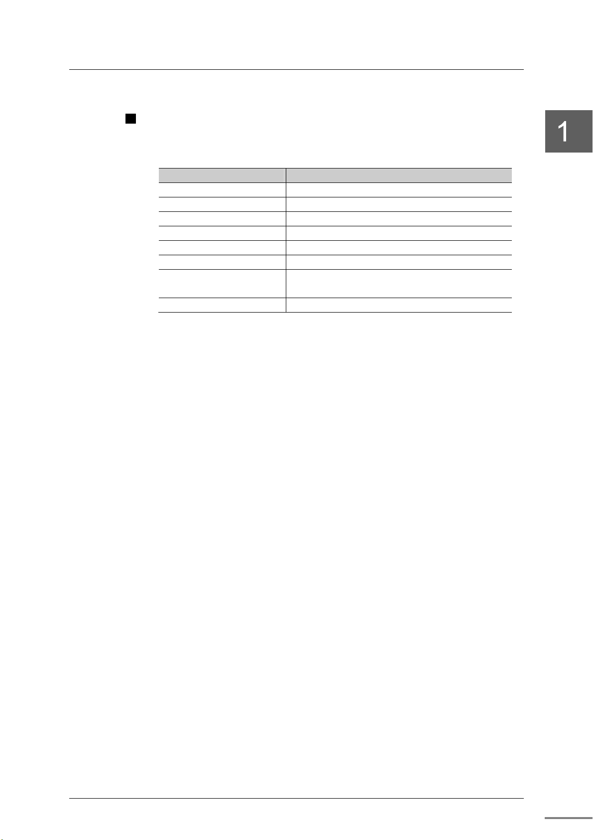
Table 1-1 Specification outline of the SA9A1 module
Item SA9A1
Event object numbers Max. 240 objects
I/O module numbers Max. 16 modules
AI object points*1 Max. 8 points
Support modules DI936, DI934, DI944, AI919
Detection cycle 1ms
Time stamp Year/Month/Day/Hour/Minute/Second/ms
Connection numbers per a
controller*2
Event data numbers Max. 2048
*1 : The AI object point store information when change information of DI object point.
*2 : If one node of SA9A1 module is used, the connection number of other SA9**
modules will decrease by one node.
*3 : A node is one element which constitutes the network.
One unit per a node*3
Two units per a node*3 in case of duplex system
Unified Controller nv series type2 SOE Function Instruction Manual
3
Chapter 1 Introducing the SA9A1 Module
A
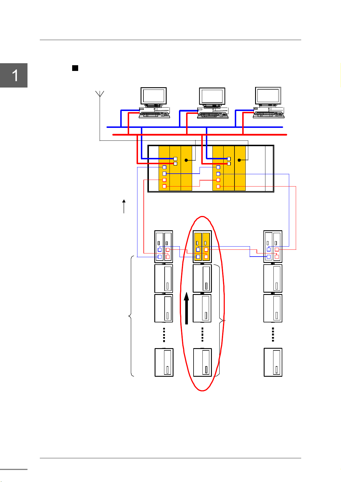
Example of system configuration
GPS antenna
Input data
Engineering tool
PU
821
SA
SA
911
911
OIS #1
Primary Secondary
FN
812
TS
811
SA
9A1
SA
9A1
PU
821
FN
812
OIS #2
Ethernet
TS
811
TC-net I/O loop
SA
911
SA
911
TC-net I/O
DO
934
DO
934
bus
DO
934
DO
934
936
936
DI
DI
DI module
or
I module
AO
928
AI
F
919
AO
928
Figure 1-1 Example of SOE function system configuration
F
4
6F8C1511
1.2 Names and Functions of the Parts
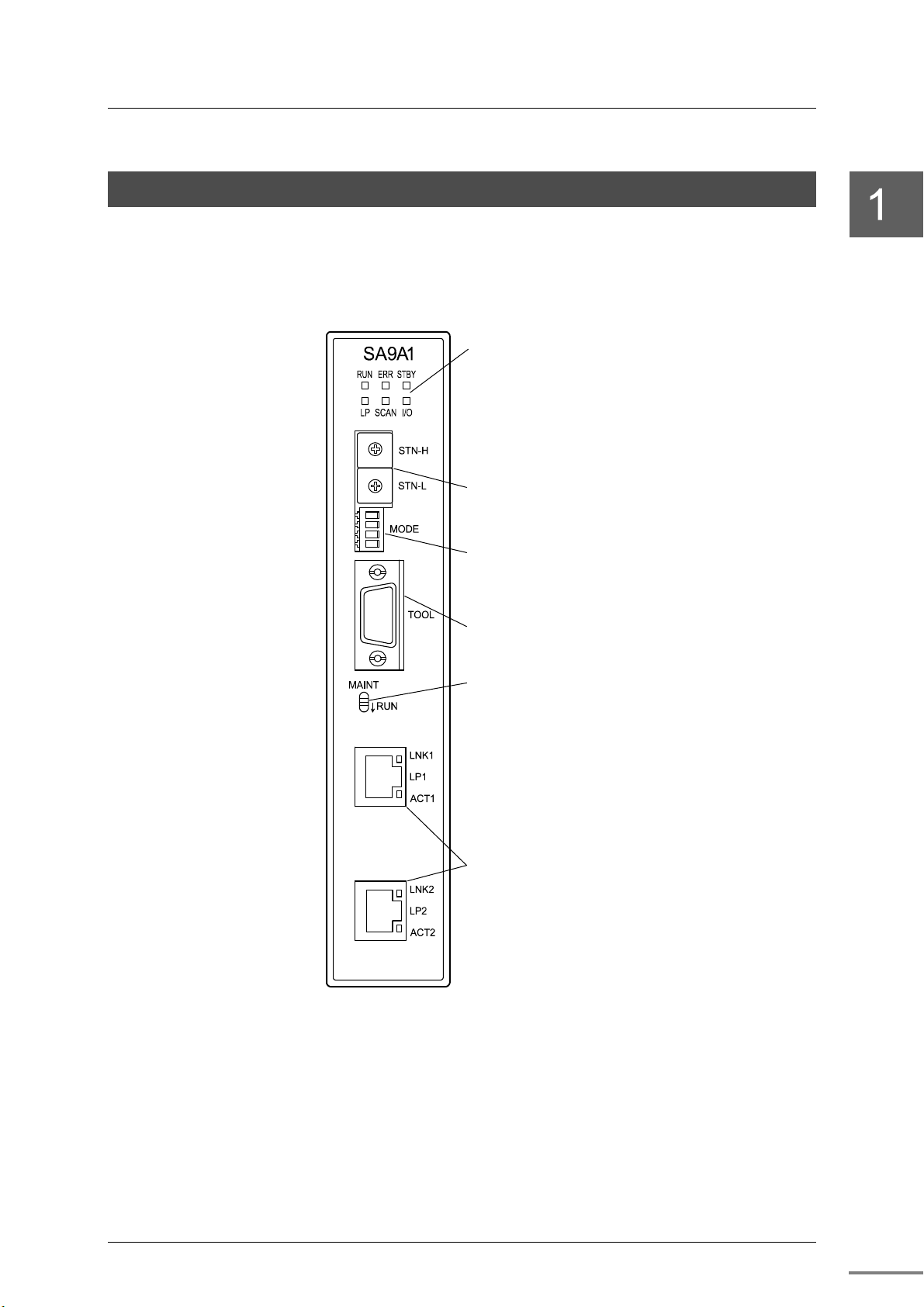
1.2.1 Names of the parts
Figure 1-2 shows the names of the parts of the SA9A1 module respectively.
State display LED
・RUN
・ERR
・I/O
・LP
・SCAN
・STS
1.2 Names and Functions of the Parts
Loop address setting switch
・STN-H
・STN-L
Operation mode setting switch
・MODE
Serial communication port
・TOOL
Maintenance switch
・MAINT
TC-net I/O loop connectors
・LP1
・LP2
Figure 1-2 Names of the parts of the SA9A1 module
Unified Controller nv series type2 SOE Function Instruction Manual
5
Chapter 1 Introducing the SA9A1 Module
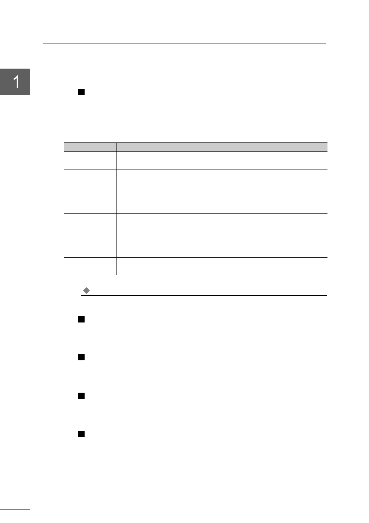
1.2.2 Functions of the parts
State display LED
The SA9A1 has state display LEDs in the front that displays the state of the
module.
Table 1-2 SA9A1 state display LED
LED name Description
RUN(green)
ERR(red)
STBY(green)
LP(green)
SCAN(green)
I/O(green)
Note
When the maintenance switch is set to the maintenance state (MAINT), all LEDs go off.
ON : Module is normal or waiting for parameter download
OFF : Module is abnormal
ON : Module is abnormal
OFF : Module is normal
ON : SA9A1 is in redundancy, standby system
OFF : SA9A1 is in redundancy, online system
or SA9A1 is in single configuration
ON : TC-net I/O loop is normal
OFF : Disconnection of TC-net I/O loop exists
ON : TC-net I/O loop side scan transmission is running normally
OFF : TC-net I/O loop side scan transmission is in suspension
Blinking : TC-net I/O loop side scan block is overlapping
ON : TC-net I/O bus side scan reception is running normally
OFF : TC-net I/O bus side scan reception is in suspension
Loop address setting switch (STN-H, STN-L)
The switch sets the address of the SA9A1 on the TC-net I/O loop in
hexadecimal. For the setting method, refer to "Chapter 3 Setting."
Operation mode setting switch (MODE)
The switch sets the operation mode of the SA9A1. For the setting method,
refer to "Chapter 3 Setting."
Serial communication port (TOOL)
This is an RS-232C port for maintenance. The connector is a 9-pin D-sub
connector (socket).
Maintenance switch (MAINT)
This switch is used to insert or remove the SA9A1 module online.
For module replacement, refer to "Chapter 2 Installation and wiring."
6
6F8C1511
1.2 Names and Functions of the Parts
TC-net I/O loop transmission connector (LP1、LP2)
The TC-net I/O transmission cable is connected. For TC-net I/O loop
connection, refer to "Chapter 2 Installation and wiring."
The connector has LEDs that indicate the transmission state of the TC-net I/O
loop. The display details are as shown in the table below.
Table 1-3 TC-net I/O loop transmission connector LED display
LED name Description
LNK1(green) Indicates that the link state of the LP1 connection side has been
established.
ON : Established (normal)
OFF : Not established (abnormal)
ACT1(yellow) Indicates that transmission or reception in the LP1 connection side is
performed.
Blinking : Transmission/reception is done (normal)
Other than above : Transmission/reception is not done (abnormal)
LNK2(green) Indicates that the link state of the LP2 connection side has been
established.
ON : Established (normal)
OFF : Not established (abnormal)
ACT2(yellow) Indicates that transmission or reception in the LP2 connection side is
performed.
Blinking : Transmission/reception is done (normal)
Other than above : Transmission/reception is not done (abnormal)
Note
When the maintenance switch is set to the maintenance state (MAINT), all LEDs go off.
Unified Controller nv series type2 SOE Function Instruction Manual
7
Chapter 1 Introducing the SA9A1 Module
8
6F8C1511

Chapter 2 Installation and Wiring
This chapter describes how to install and wire the TC-net I/O base unit
and the SA9A1 module.
2.1 Types of I/O Base Units ···········································
2.2 Installing the Module ···············································
2.2.1 Vertical Installing of the module ································ 13
2.2.2 Horizontal Installing of the module ···························· 17
2.3 Connecting the TC-net I/O Loop Transmission Cable ·· 18
2.4 Replacing the Module ··············································
2.5 Removing the Base Unit ··········································
12
13
19
20
9
Chapter 2 Installation and Wiring
y
A
WARNING
WARNING
CAUTION
Before installing or removing the module,
make sure that the basic unit to which the
SA9A1 module is installed is turned off.
Otherwise, it may cause an electric shock.
Do not touch the interior of the product
except the switches.
It may cause an electric shock.
Install it under an environment that satisfies
the product specifications.
When installing it under an environment that does
not satisfy the product operating temperature range,
apply forced cooling with cooling equipment.
Operating temperature range: 0 to 55C
Mandatory
Prohibited
Prohibited
CAUTION
CAUTION
CAUTION
CAUTION
Before installation or wiring, remove the
static electricity from your body.
The static electricity accumulated in the human body ma
cause failure of the product.
Do not touch the cables carelessly.
pplying stress to the cables may cause malfunction or
accidents.
Do not perform wiring, insertion of the
TC-net I/O bus cable connector, or
installation, removal, or replacement of the
base unit while the power is on.
It may cause an electric shock or malfunction.
When installing the product to the base unit, be careful not
to snap or bend the TC-net I/O bus connector pins.
When installing the product to the basic
unit, do not break or bend the pins of the
TC-net I/O bus connector.
Prohibited
Prohibited
Prohibited
Prohibited
If it is difficult to insert the module to the
CAUTION
10
6F8C1511
basic unit, remove it once and try again
rather than forcing it.
Mandatory
 Loading...