


E6580718②
RS485 Converter Unit Instruction Manual
RS4001Z-0
Table of Contents
1. OVERVIEW .............................................................................................................................................................. 4
2. COMMUNICATION SPECIFICATIONS.................................................................................................................... 4
3. NAMES AND FUNCTIONS OF MAIN PARTS.......................................................................................................... 5
4. CONNECTION AND START-UP.............................................................................................................................. 6
5. DIMENSIONS........................................................................................................................................................... 8
6. COMMUNICATION PARAMETERS ......................................................................................................................... 9
7. SPECIFICATIONS.................................................................................................................................................... 9
8. WARRANTY............................................................................................................................................................. 9
This RS485 communication unit cannot use at TOSVERT VF-S7/S7e inverter has a CPU whose version
is V100 to V102.
For checking the version number of the CPU, refer to the “Monitor” paragraph in the instruction manual
of the inverter.
(C)TOSHIBA CORPORATION 1998
All Rights Reserved.
NOTE
1. Make sure that this instruction manual is delivered to the end user of the RS485 converter unit.
2. Read this manual before installing or operating the RS485 Converter unit. And keep it in a safe
place for reference.

E6580718
‑
‑‑
‑
1‑
Introduction
Thank you for purchasing the “RS485 Converter Option Unit(RS4001Z)” for TOSVERT series
inverter. Read the safety precautions in the “Inverter Instruction Manual” before powering up your
inverter. Using this RS485 Option Unit, a communication between the inverter, which has the
common serial option (communication) connector, and a host computer is available.
Please read the entire manual carefully before attempting to control your inverter via RS485 serial
connection. Besides this instruction manual, the “Serial Communications Function Manual” is
needed to develop software which communicates with the inverter.
In addition, it has this manual kept to the operator using "RS485 Converter Unit", and please use it
for future maintenance and inspection.
[Explanation of part number of RS-485 Option Unit]
RS4001Z - 0
[Check of accessories]
The RS-485 Option Unit is shipped together with the following accessories in the same package.
On opening the packing case, check to see if the following accessories are contained or not.
(1) Instruction manual of RS-485 Option Unit……1 copy
(E6580718)
(2)Connector terminal (remover side)……1 pcs
(MVSTBW2.5/6-ST-5.08 : Phoenix Contact)
Part number of connection cable
between the Inverter and Option Unit
Cable length
CAB0011 1m (1.2m, 4ft)
CAB0013 3m (3.6m, 12ft)
CAB0015 5m (4.8m, 16ft)
(Note) The RS-485 Option Unit (Part Number : RS4001Z)
is not provided with connection cable between the inverter
and Option Unit. This should be purchased separately.
Revision number
Symbol of RS-485
Model number of RS-485 Option Unit
Cable length Z: Without cable
(Cable length between inverter and Option Unit)

E6580718
‑
‑‑
‑
2‑
Carefully read the following notes
Safety precautions
On the inverter and in its instruction manual, important information is contained for preventing
injuries to users and damages to assets and for proper use of the device. Read the instruction
manual attached to the inverter along with this instruction manual for completely understanding the
safety precautions and adhere to the contents of these manuals.
■■■■
Handling in general
Danger
Never
Disassemble
▼
Never disassemble, modify or repair the product.
Disassembling the inverter could cause electric shocks, fire or injuries.
For repairs, call your agency.
Prohibited
▼ Do not remove connectors when the power is on.
It could lead to electric shocks.
▼ Do not put or insert foreign objects such as waste cable, bars, or wires into the product.
It could lead to electric shocks or fire.
▼
Do not splash water over the product.
It could lead to electric shocks or fire.
Mandatory
▼
Wiring should be conducted after turning the inverter power off.
▼ Turn off the power immediately in case any abnormalities such as smokes, smells or abnormal
noise are found.
Neglect of these conditions could lead to fire.
For repairs, call your agency.
■
Transportation and installation
Danger
Prohibited
▼
Do not install or operate the inverter if it is damaged or any part is missing from it.
Operating the inverter in a defective condition could lead to electric shocks or fire.
For repairs, call your agency.
▼ Do not put any inflammable material near the product.
It could catch fire if the product sparks because of a breakdown and the like.
▼ Do not install the product where it could be splashed with water and the like.
It could lead to electric shocks or fire.
Mandatory
▼ The product must be used under environmental conditions prescribed in this instruction manual.
Using the product under conditions not specified by the instruction manual could lead to
breakdown.
Cautions
Prohibited
▼ Do not install the product in any place subject to vibrations or it could fall.
Otherwise it can cause injury to people.

E6580718
‑
‑‑
‑
3‑
■■■■
About operation
Danger
Prohibited
▼
Do not wipe the body with a wet cloth.
It could lead to electric shocks.
▼ Do not pull on the cable
It could cause damage or error.
■
About disposal of the product
Cautions
Mandatory
▼
Dispose of the product as an industrial waste.
Unless it is disposed of as an industrial waste, it will become risks for human injury.
■
Cautions on use
Cautions
▼
Avoid installation locations that may be subjected to rapid changes in ambient temperature
or/and humidity.
▼
Route the transmission cable separate from the inverter input/output power wiring.
When disconnecting connection cable, make sure to hold its connector with care not to give
unreasonable stress to the cable and the unit.
▼
Since connectors of optional cables have locking
pawls for disconnection prevention at the inverter and the Option Unit, disconnect such a
connector while pressing the pawl by finger for unlocking.
▼
Mount the Option Unit securely on the panel, otherwise it could fall and cause malfunction or
breakdown.
▼
Connect an electromagnetic contactor or the like between the inverter and the power source to
secure external control of emergency stop of operation.
▼
Do not assign the same inverter number to more than one inverter in the same system.
▼
The inverter’s EEPROM has a life of 10,000 write cycles. Do not write to the same EEPROM
address more than 10,000 times.

E6580718
‑
‑‑
‑
4‑
1. Overview
By using RS485 Converter Unit, a network can be constructed that allows communication between a
host computer and multiple inverter units. A maximum of 32 Option Units can be connected on the
same network. And two inverters can be connected to one RS485 Converter Unit. A maximum of 64
inverters can be connected on the same network.
2. Communication specifications
Item Specifications
Interface Conforming to EIA RS485 standard
Configuration 4-wire, bus type (terminating resistor is necessary at each
end of system)
Communication Distance 1,000m maximum
Connection Points 32 units maximum
Number of ASDs per one Option Unit 2 units maximum
Number of ASDs on the Same Network 64 units maximum
Communication Line Isolation Not isolated
Synchronization Method Start-stop synchronization
Communication Speed 1200/2400/4800/9600 baud selectable (parameter and
switch selection)
Other Please be sure to add a parity bit.
(This product does not fit to none parity bit. )
RS485
Converter Unit
Inverter
Host computer

E6580718
‑
‑‑
‑
5‑
■
Switch for communication speed
& Termination resistor setting
(Note) Set the switch before power on
(1) Communication speed setting (SW1, 2)
Set the communication speed to the same
as inverter’s (F800).
(2) Terminating resistor setting (SW3, 4)
SW3-ON : Connecting receiving side
SW4-ON : Connecting transmitting side
Connect the terminating resistor to both
end of system.
3. Names and functions of main parts
■
Connector terminal (removal side)
*Wire size (shielded twisted-pair cable recommended)
Bare wire (without stick lug) : 0.4(0.2)~1.5mm
2
(Refer to a page 6)
Phoenix Contact TWIN terminal : (wire size below) × 2
Part number: AI-TWIN2×0.5-8WH, AI-TWIN2×0.75-8GY, AI-TWIN2×1-8RD, AI-TWIN2×1.5-8BK
* Others
COMBICON terminal blocks such as the Phoenix Contact TMSTBP series that allows signal
branching can be used in place of included terminal.
INVERTER 1, INVERTER 2:Communication connector
Connect to the inverter’s common serial conector with the
option cable.
Setting Baud rate
SW1 SW2
OFF OFF 1200
ON OFF 2400
OFF ON 4800
ON ON 9600
OFF(OPEN
)
ON
(Back side of the UNIT)
SHIELD
Shield terminal
Connector terminal
(socket side)
Insert removal
terminal block
Connector terminal
(removal side)
Insert socket
terminal block
RXA, RXB
Receiving Terminal
TXA, TXB
Transmitting terminal
SG
Signal common terminal
SW
INVERTER2
INVERTER1
RS485
OPTION UNIT
R R T T S S
X X X X G H
A B A B I
E
L
D
M3
7mm
Terminal pitch : 5.08mm
(Front side of the UNIT)

E6580718
‑
‑‑
‑
6‑
4. Connection and start-up
■
Procedure
(1) Set the communication speed to SW on the RS-485 Option Unit.
(2) Connect terminating resistor in both ends of units. The RS-485 Option Unit has internal
terminating resistor. Set SW3 and SW4 to ON to connect these terminating resistors.
(Refer to a page 5)
(3) Install the RS-485 Option Unit on a metal panel.
(4) Connect the cable to the removable terminal block. If the stick-lugs are not used, strip the
insulation from the wire and insert the wire directly into the terminal. Be sure not to short any
wires. Wire the cable as shown in the figure. Use a common cable in the system.
(5) Connect the shield of the twisted pair cable to the SHIELD terminal on each RS-485 Option Unit,
and make the ground connection. Do not connect host computer ground to a power ground or
any other noise-producing ground connection.
(6) Insert the removable terminal block back into the RS-485 Option Unit.
(7) Connect the communication connectors (INVERTER1 and INVERTER2) of the RS-485 Option
Unit to the inverter’s common serial option (communication) connector of the with the optional
cable.
(8) Turn on the power of the inverter.
(9) Set the communication parameters of the inverter. (Refer to a page 9)
Shielded twisted-pair cable
0.2~1.5mm
2
(AWG size: 24~16)
(*1)
(recommendation: More than 0.4mm
2
(*2)
)
Terminating
resisitor
120Ω-1/2W
SW3,SW4=OFF
Ground
(100Ω or less)
Host Computer
RS485
Option Unit
TXA
TXB
RXA
RXB
SG
FG
RXA
RXB
TXA
TXB
SG
SHIELD
RXA
RXB
TXA
TXB
SG
SHIELD
RXA
RXB
TXA
TXB
SG
SHIELD
(*2)
:When transmission
distance exceeds 500m,
please use 0.75mm
2
two
or more cables.
(*1)
:
It is one electric-wire size at
two wires connection.
See page5 when stick t
erminal is used.
SW3,SW4=OFF
SW3,SW4=ON
Set terminating resistor
RS485
Option Unit
RS485
Option Unit
E6580718
‑
‑‑
‑
7‑
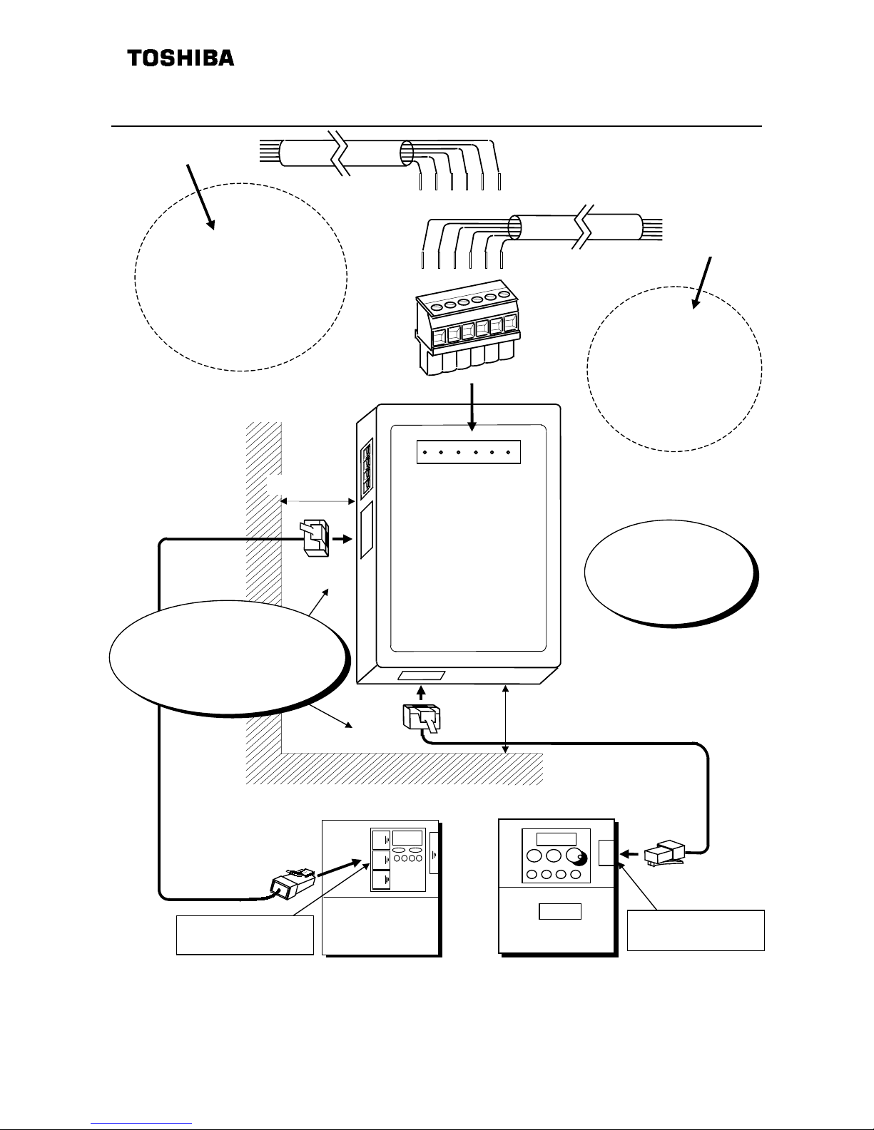
■ Cable connection
1.RXA
2.RXB
3.TXA
4.TXB
5.SG
6.SHIELD
Please fix a cable.
1.Transmit positive line (TXA)
2.Transmit negative line (TXB)
3.Receive positive line (RXA)
4.Receive negative line (RXB)
5.Signal line ground (SG)
6.Shield ground (FG)
Another
RS-485
Option Unit
Host Computer
123456
123456
R R T T S S
X X X X G H
A B A B I
E
L
D
SW
INVERTER2
INVERTER1
RS485
OPTION UNIT
More than 5cm
More than 5cm
Leave a space more than 5cm on left
and bottom side of option unit for
connecting the communication cable.
Example:VF-A7
Common serial option
connector
Example:VF-S7
VF-S7
Common serial option
connector
VF-A7

E6580718
‑
‑‑
‑
8‑
5.0
5. Dimensions
Dimensions of the RS-485 Option Unit (with connector terminal (removal side)) are shown below.
Make sure a space for connecting cables.
Use M3 screws to install.
■RS485 Converter Unit
3.2 Hole
(Unit: mm)
45°
3.2 hole
2.8
13.5
19.6
15.9
1.0 1.0
13.2
60.0
28.0
13.5
88.0
1.01.0
2.0
49.7
27.1 22.6
19.6
15.9
12.6
100.0
15.9
19.9 31.6
16.0
9.0
2.0
112.0
90.0 11.0
11.0
30.0
SW
INVERTER1
RS485
OPTION UNIT
INVERTER2

E6580718
‑
‑‑
‑
9E‑
6. Communication parameters
Be careful the parameter setting range, initial value, etc. may change with the inverter models.
Function Parameter Note
Communication
speed
f800
Communication speed must be the same in the same network
(Inverters, Host computer, RS485 units).
Parity
f801
Parity setting must be the same in the same network (Inverters, Host
computer).
In addition, None parity is not available.Select odd or even parity bit.
Inverter number
f802
Do not assign the same inverter number in the same network (Inverters,
Host computer).
Need to set the inverter number in the transmission format.
7.
Specifications
Item Specifications
Part number RS4001Z-0
Service environment Indoors. Altitude of less than 1000m (3280 ft).
Must not be exposed to direct sunlight, subjected to corrosive and/or
explosive gases, vapor, dust, chips, cutting oil, grinding agent, etc.
Ambient temperature From -10°C to +50°C (14°F to 104°F)
Storage temperature From -25°C to +65°C (-13°F to 149°F)
Relative humidity 20 to 90% (no condensation allowed)
Vibration 5.9m/s2 or less
Cooling system Self-cooling
8.
Warranty
Any part of the RS485 Option Unit that proves defective will be repaired and adjusted free of charge
under the following conditions:
1. If and when a trouble occurs on the option unit properly installed and handled within one year of
delivery, and if the trouble is clearly attributable to defects inherent in our design and manufacture,
the product will be repaired free of charge.
2. The warranty covers only the delivered option unit.
3. Even in the term of the warranty, repair/adjustment service will be charged for the following cases.
1) Fault or damage resulting from misuse, unauthorized modification or repair.
2) Fault or damage resulting from falling down of the product or traffic accident during transportation.
3) Fault or damage originating from fire, salt water/salty breezes, some kind of gas, earthquake,
storm or flood, lightning, abnormal supply voltage, other natural disasters.
4) Fault or damage caused by improper use of this option unit as it is used for a purpose out of its
original function.
4. If there is another special warranty contracted for this option unit , the special warranty has
priority over this warranty.
 Loading...