

PROGRAMMABLE CONTROLLER
PROSEC T1
RS232C/RS485
MULTI-DROP ADAPTER
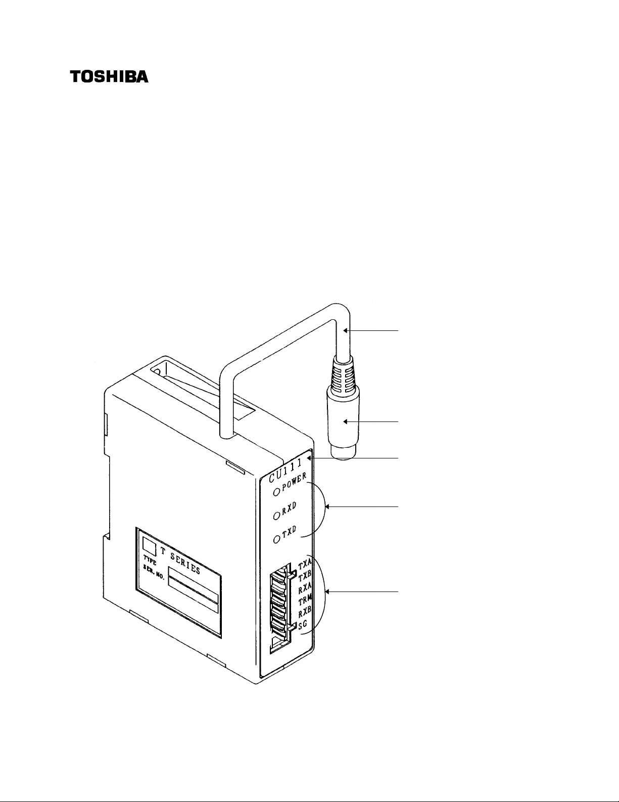
CU111
n
USER’S MANUAL
T1 connection cable
T1 side connector
Type identification
Status LEDs
RS485 Terminal block
1
Precaution and Checks
Thank you for purchasing a TOSHIBA product.
Please confirm the product has arrived in good condition and use it according to this guide.
This guide has been prepared for users who have general knowledge of the programmable
controllers and control systems. If any parts of this guide are not clear to you,contact
TOSHIBA agent.
CAUTION
1. Use the multi-drop adapter in the environment specified in the T1 user's
manual. Using the multi-drop adapter in the illegal environment may lead to
electric shock,fire,failure,or malfunction.
2. Neither disassemble nor modify the multi-drop adapter. Otherwise, it may get
fired,failed,or malfunctioned.
3. The multi-drop adapter CU111 is designed for the T1. Do not use it for other
purposes.
4. Turn off the power of the T1 main unit before connecting the cable.
5. Do not pull the T1 connection cable without grasping the connector. It can
cause cable disconnection.
6. Do not extend the T1 connection cable.
n Unpacking confirmation
Check the product matches the type notation on the packing case.
Also, check the followings are in the packing case.
Multi-drop adapter (CU111) 1
Metal fitting for screw 1
Terminal block (attached) 1
Guide (this document) 1
n Product identification
Product type : CU111
Part number : TCU111**S
n Handling precautions
The multi-drop adapter specification confirm to the T1 main unit.
Please read the following documents.
T1 USER’S GUIDE (UG-TS07***-E007)
T1 USER’S MANUAL - Basic Hardware and Function - (UM-TS01***-E001)
T1 USER’S MANUAL - Option Cards and I/O Modules - (UM-TS01***-E002)
T1 USER’S MANUAL - Computer Link Function - (UM-TS01***-E003)
Also, keep this guide and related manuals so that you can read them anytime while the T1
is in operation.
2

CU111 Specifications
1.Overview
Connecting the RS232C/RS485 multi-drop adapter (CU111) to the T1’s programmer port, you
can use the RS485 computer link function.
By this function, long-distance and one -to- N communications become available.
2.Specifications
(1)Function specification
Item Specification
Connection RS232C DIN - 8pin (T1 programmer port connector)
RS485 Removable terminal block 6pin
Length of T1 connection cable 30cm
Status LEDs 3 (Refer to the following table)
Isolation Non isolation between RS232C and RS485
Power Supply 5Vdc from T1 main unit
Current consumption 75mA
Size
(2)Transmission specification
Item Specification
Interface Conforms to RS232C (T1 side)
Transmission distance 30cm (between T1 and adapter)
Transmission speed 9600 bps
Framing Start bit 1bit (Fixed)
Number of stations Max. 32
30mm(W) × 90mm(H) × 75mm(D) (except cable)
Conforms to RS485 (Host side)
Max. 1km (RS485 )
Dta bit 8bits (Fixed)
Parity Odd parity/ Non (automatic detection)
Stop bit 1bit (Fixed)
(3)RS485 transmission cable
Shieled twisted cable which conforms to the RS485, should be used for communication
cable. It’s recommended that 0.9mm diameter or more, 3 pairs or more cables are used.
(4)Operation Status LEDs
Name Direction LED Status
(color) Lit Not Lit
POWER
(green)
RXD
(green)
TXD
(green)
Host → T1
T1 → Host
5V power is normal and
connected to T1
Data receiving
(RXD = 0)
Data transmitting
(TXD = 0)
3
5V power is not normal.
Data not receiving
(RXD = 1)
Data not transmitting
(TXD = 1)

CU111 Installation
30mm
23mm
15mm
3.Installation
1.Installing the adapter
Either DIN rail or screw mounting is available.
The length of the T1 connection cable is 30cm. Consider the cable length when installing
the multi-drop adapter.
Please read the installation section of the T1 user’s manual.
(Mounting on a DIN rail)
Mounting
(1)Hang the adapter on the DIN rail at first.
Next, push the adapter and hook the
DIN rail.
(2)Please check that the DIN rail bracket
hooks the DIN rail.
DIN rail
Adapter
(35mm)
DIN rail bracket
(Screw mounting)
Attach the metal fittings for screw to the DIN rail bracket and screw securely using the M3
screws.
2-M3
adapter
95mm
90mm
fitting for screw
2.Connecting the dedicated cable
Turn off the power of the T1 main unit. Connect the T1 side connector to the T1’s
programmer port and RS485 cables to the terminal block.
Do not connect or remove the cables while power to the T1 is on.
T1 dedicated cable
Programmer
T1 CU111
port
Terminal block
RS485
4

CU111 Configuration
T1
T1
T1
R
4.System configuration example
[ one-to-one configuration ]
IN
PROSEC
TOSHIBA MDR16
OUT
T1 main unit : T1-16/28/40
[ one-to-N configuration ]
RS485RS232C
CU111
Operator interface unit
CU111 CU111
RS232C
IN
PROSEC
TOSHIBA MDR16
OUT
5.Circuit configuration
T1
Connection
Cable
RS485
ADP-
RS232C
6237B
RS232C
IN
PROSEC
TOSHIBA MDR16
OUT
Multi-drop adapter
RS485
Gate
Controller
……………………
RS485 TransceiverRS232C Transceiver
Other T-sereis PLCT1 main unit : T1-16/28/40T1 main unit : T1-16/28/40
RS485
Terminal
Block
TXARX1
TXBCRS1
RXARTS
TX1
TRM
RXB
SG
P5
GND/SG
Supervisor of
Power Suplly
TTermination registors : 1/2W 120Ω
5
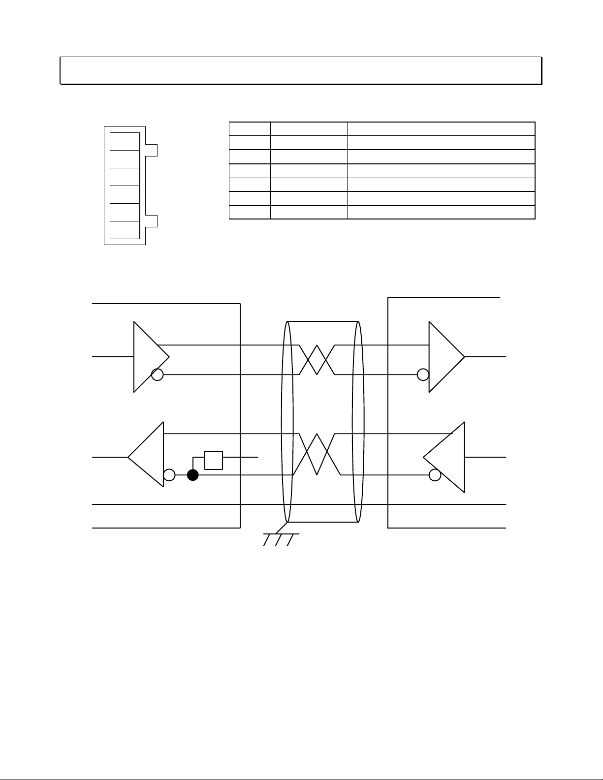
6.Computer Link (RS485) interface
(1)Computer Link (RS485) signal name and pin assignment
Pin No. Signal Name Function
1
2
3
4
5
6
(2)Computer Link (RS485) interface connection
TXA
TXB
RXA
TRM
RXB
SG
1 TXA
2 TXB
3 RXA
4 TRM Termination
5 RXB
6 SG Signal Ground
Sheilded
twisted-paired cable
CU111 connection
CU111→RS485 (In phase signal)
CU111→RS485 (Reverse signal)
CU111←RS485 (In phase signal)
CU111←RS485 (Reverse signal)
TXA RXA
TXB
R
RXB
RS232C/RS485
Multi-drop adapter
CU111
1
RXDTXD
2
RXB
3
4
TRM
5
6
TXARXA
TXDRXD
TXB
SGSG
Host Equipment
RS485 Interface
Short between RXA(Pin No.3) and TRM(Pin No.4) for termination of one-to-one configuration
at CU111. Refer to the next page.
Note
¬ Use the shielded twisted-paired cable for noise immunity and ground the cable shield at
one end.
- Connect SG (Signal Ground) each other.
® The adapter does not have the frame ground (FG) terminal, so please ground directly.
¯ Please make the program transmitting again.
6

CU111 Connection
T1
T1
T1
T1
TRM
RXA
TXB
TXA
TERM
RXA
TXB
TXA
RXB
RXBSGSG
R
R
(3)Computer Link signal and connect termination registors
[ one-to-one configuration ]
RS485
CU111
IN
PROSEC
TOSHIBA MDR16
OUT
RS232C
RS232C
T1 main unit : T1-16/28/40
HOST
Connect cables according to the above diagram.
Short between RXA and TRM(TERM) for termination at the end of both CU111 and ADP6237B.
[ one-to-N configuration ]
R
TXA
RS232C
TXB
RXA
R
TERM
RXB
SG
ADP-6237B
HOST
SGR
T
R
T
CU111
T
X
R
X
X
X
B
M
A
B
A
R
T
T
X
X
X
A
B
A
SGR
T
X
R
B
M
R
T
T
X
X
X
A
B
A
SGR
T
X
R
B
M
RS232C
IN
PROSEC
TOSHIBA MDR16
OUT
IN
PROSEC
TOSHIBA MDR16
OUT
IN
PROSEC
TOSHIBA MDR16
OUT
Connect cables according to the above diagram.
Connect termination registor 1/2W-220Ω between RXA and TXB, and between TXA and
TXB at both terminal stations.
7

TOSHIBA INTERNATIONAL (EUROPE) LTD.
1 Roundwood Avenue
Stockley Park, Uxbridge
Middlesex, ENGLAND UB11 1AR
Tel: 0181-756-6000 Fax: 0181-848 4969
TOSHIBA INTERNATIONAL
CORPORATION PTY. LTD.
2 Morton Street, Parramatta
N.S.W. 2150, AUSTRALIA
Tel: 02-9768-6600 Fax: 02-9890-7542
TOSHIBA INTERNATIONAL CORPORATION
Industrial Division
13131 West Little York Road
Houston, TX. 77041, U.S.A.
Tel: 713-466-0277 Fax: 713-466-8773
UG-TS01***-E011
1997-02(2)
8
TOSHIBA CORPORATION
Industrial Equipment Department
1-1, Shibaura 1-chome, Minato-ku
Tokyo 105, JAPAN
Tel: 03-3457-4900
 Loading...