


FILE No. A90-9611
SERVICE MANUAL
AIR CONDITIONER
SPLIT TYPE
2 WAY CASSETTE TYPE, HEATPUMP
RAV-103TUH-PE
RAV-133TUH-PE/RAV-132AH-PE
RAV-163TUH-PE/RAV-162AH-PE
Printed in UK Dec 1996
s

CONTENTS
1. SPECIFICATION .....................................................................................................................................................3
2. CONSTRUCTION VIEWS .......................................................................................................................................6
3. WIRING DIAGRAM ..................................................................................................................................................8
4. SPECIFICATIONS OF ELECTRICAL PARTS............................................................................................................ 10
5. INTERFACE PCB .................................................................................................................................................... 12
6. REFRIGERANT PIPING DIAGRAM........................................................................................................................... 13
7. PERFORMANCE CHARACTER ........................................................................................................................... 15
8. EXPLODED VIEWS AND PARTS LISTS ............................................................................................................... 17
SUMMARY
• The units referred to within this manual conform with the protection requirements of Directives 89/336/EEC
Electromagnetic Compatibility and 73/23/EEC Low Voltage.
• Operating conditions of units are as follows:
OUTDOOR TEMPERATURE -2 TO 43°C (COOL)
-10 TO 21°C (HEAT)
ROOM TEMPERATURE 18 TO 32°C (COOL)
15 TO 29°C (HEAT)
ROOM HUMIDITY LESS THAN 80% (COOL)
Note 1 : Cooling Capacity is based on the following temperature conditions:
Indoor air inlet temperature 27°C DB, 19°C WB.
Outdoor air inlet temperature 35°C DB.
Note 2: Heating Capacity is based on the following temperature conditions:
Indoor air inlet temperature 20°C DB.
Outdoor air inlet temperature 7°C DB, 6°C WB.
Note 3: For details on the Remote Controller and Control Circuits
refer to Service Manual A90-9503.
-2-
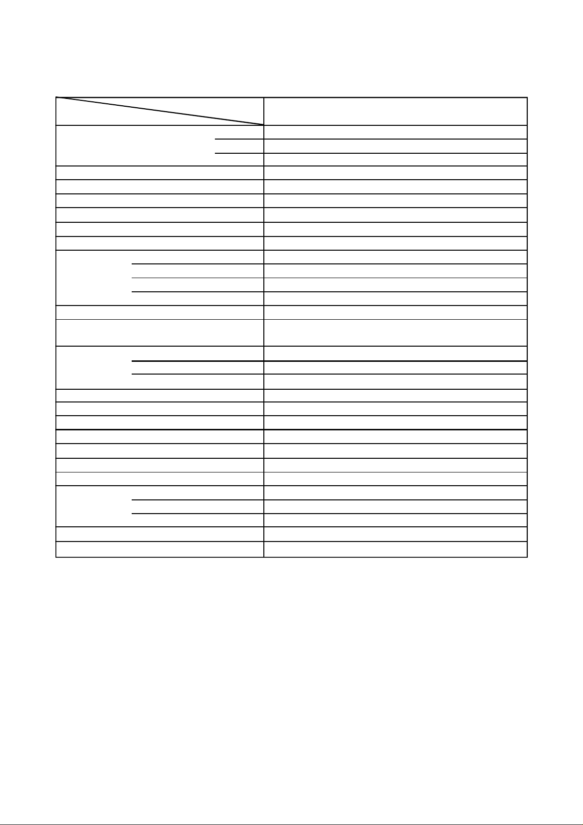
1.SPECIFICATION
ITEM
Power source
Power consumption
Power factor
Running current
Starting current
Operating noise (SPL) (High, Med, Low)
Refrigerant
Name of refrigerant
Larger side size
Interconnection
pipe
Coupler style
Smaller side size
Coupler style
Condensate drain pipe diameter
Appearance colour
Height
Dimensions
Width
Depth
Net weight
Heat exchanger type
Indoor fan type
Air volume
Fan motor output
CEILING PANEL Model
Appearance colour
Height
Dimensions Width
Depth
Net weight
Air filter
MODEL
Phase
V
Hz
kW
%
A
A
dB(A)
mm
mm
mm
mm
mm
mm
kg
m3/h
W
mm
mm
mm
kg
RAV-103TUH-PE
1
220-240
50
0.07
93
0.33
0.6
40/36/34
R-22
Ø12.7 (1/2)
Flare
Ø6.4 (1/4)
Flare
Ø25.5(OD)
Grey (zinc galvanized steel
+ Thermal insulator)
190
910
480
23
Finned tube
Transverse flow fan
550
7 x 2
RBC-U133PG(W)-PE
Silky white (Munsell 2.9Y8.9/0.8)
25
1050
550
4.5
Washable
Specifications are subject to change without notice.
-3-
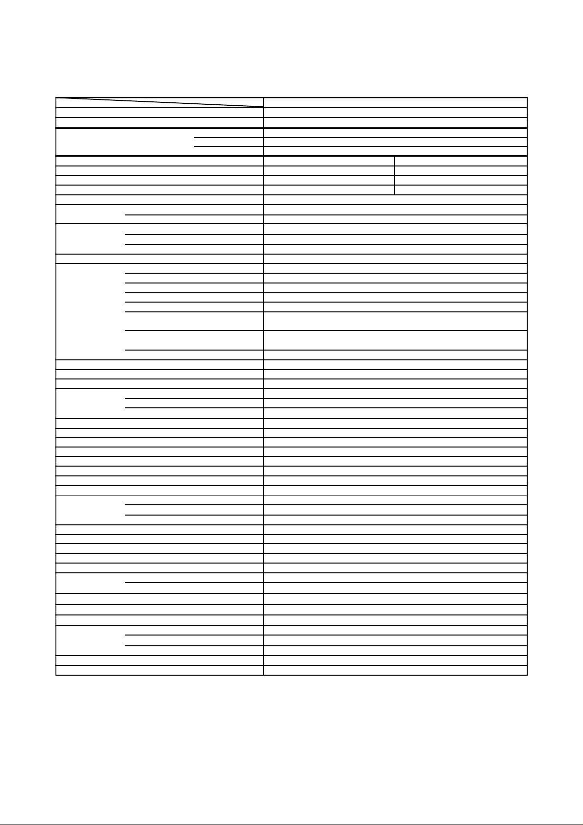
ITEM
Cooling capacity
Power source
MODEL
kW
kW
Phase
V
Hz
RAV-133TUH-PE
3.6
4.2Heating capacity
1
220-240
50
HEATINGCOOLING
Power consumption
Power factor
Running current 10.3 10.7
Starting current
Operating noise (SPL)
Refrigerant
Indoor unit (High, Med, Low)
Outdoor unit
Name of refrigerant
Charge volume
Add. volume (20-30m)
kW
%
A
A
dB(A)
dB(A)
kg
g/m
Refrigerant control
Larger side size
mm
Coupler style
Smaller side size
mm
Coupler style
Interconnection pipe
Standard length
Maximum length
(of one way) *1 m
m
2.1
89 89
60
40/36/34
50
R-22
1.2
35
Capillary tube & Expansion valve
Ø12.7 (1/2)
Flare
Ø 6.4 (1/4)
Flare
7.5
30
2.2
Maximum height difference
If indoor unit higher m 15
If outdoor unit higher m 30
Condensate drain pipe diameter mm
Ø 25.5 (OD)
INDOOR UNIT Model RAV-133TUH-PE
Appearance colour Grey (zinc galvanized steel + thermal insulator)
Height mm 190
Dimensions
Width
mm
910
Depth mm 480
Net weight kg 23
Heat exchanger type
Finned tube
Indoor fan type Transverse flow fan
Air volume m3/h 700
Fan motor output
Air filter
W 7 x 2
Washable
OUTDOOR UNIT Model RAV-132AH-PE
Appearance colour Bronze white (Munsell 6Y7.5/1)
Dimensions
Height mm
Width
mm
Depth mm
740
880
310
Net weight kg 61
Heat exchanger type
Outdoor fan type
Finned tube
Propeller fan
Air flow volume m3/h 2,700
Fan motor output
Compressor
Protective device
CEILING PANEL Model
Model
Output
W
kW
High pressure switch, Fuse, Crankcase heater, Overload relay, Bimetal thermostat
39
PH230X3-4LS
1.5
RBC-U133PG(W)-PE
Appearance colour Silky white (Munsell 2.9Y8.9/0.8)
Dimensions
Net weight
Air filter
Height mm
Width mm
Depth mm
kg
25
1050
550
4.5
Washable
Specifications are subject to change without notice.
* Note 1 : These mean actual length.
-4-

ITEM MODEL
Cooling capacity
Heating capacity
Power source
Power consumption kW
Power factor %
Running current A
Starting current
Operating
noise (SPL)
Refrigerant
Refrigerant control
Interconnection
pipe
Condensate drain pipe diameter ø 25.5(OD)
INDOOR UNIT Model
Appearance colour
Dimensions
Net weight kg
Heat exchanger type
Indoor fan type
Air volume
Fan motor output
Air filter
OUTDOOR UNIT Model
Appearance colour
Dimensions
Net weight
Heat exchanger type
Outdoor fan type
Air flow volume
Fan motor output
Compressor
Protective device
CEILING PANEL Model
Appearance colour
Dimensions
Net weight
Air filter
Indoor unit (high/med/low)
Outdoor unit
Name of refrigerant
Charge volume
Add. volume (20-30m) g/m
Larger side size
Coupler style
Smaller side size
Coupler style
Standard length m 7.5
Maximum length
(of one way) *1 m
Maximum height difference
If indoor unit higher
If outdoor unit higher
Height
Width
Depth mm 480
Height mm
Width
Depth mm
Model
Output
Height
Width
Depth
kW
kW
Phase
V
Hz
COOLING
2.3
90
11.1
A
dB (A)
dB (A)
kg
mm ø 12.7 (1/2)
mm ø 6.4 (1/4)
m
mm
Grey (zinc galvanized steel + thermal insulator)
mm 190
mm 910
m3/h
W
mm
kg
m3/h
W
kW
High pressure switch, Fuse, Crankcase heater, Overload relay, Bimetal thermostat
mm
mm
mm
kg
RAV-163TUH-PE
4.5
5.0
1
220-240
50
60
41/37/35
50
R-22
1.6
35
Capillary tube & Expansion valve
Flare
Flare
30
15m
30
RAV-163TUH-PE
23
Finned tube
Transverse flow fan
750
7 x 2
Washable
RAV-162AH-PE
Bronze white (Munsell 6Y7.5/1)
740
880
310
61
Finned tube
Propeller fan
2,700
39
PH250X3-4LS
1.5
RBC-U133PG(W)-PE
Silky white (Munsell 2.9Y8.9/0.8)
25
1050
550
4.5
Washable
HEATING
2.2
90
10.6
Specifications are subject to change without notice.
* Note 1 : These mean actual length.
-5-
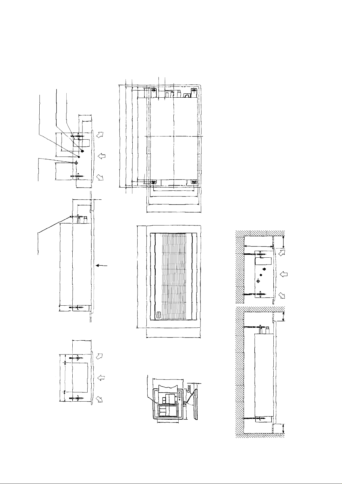
2.1 Indoor unit
Space required for service and installation
RAV-103TUH-PE
RAV-133TUH-PE
RAV-163TUH-PE
2. CONSTRUCTION VIEWS
73
20
40
110
66
90
Wiring connection
Refrigerant piping joint
( Gas ∅ 12.7)
Refrigerant piping joint
( Liquid ∅ 6.4)
186
267
170
Drain pipe joint
(outer ∅ 25.5)
Hanger bolt
(4- M10)
840
190
156
140
131
96
Panel outer dimension 1050
25
A
840
Ceiling opening 1010
Hang bolt pitch 930
40
60
40
20
1050
410
Hang bolt pitch 480
Ceiling opening 510
Panel outer dimension 550
View A
200
600
Minimum
70
480
130
290
70
190
Long hole
2-4.5 x 9L
-6-
120
83.5
550
12.5
Remote controller
600
Minimum
600
Minimum
(Unit: mm)

2.2 Outdoor unit
RAV-132AH-PE
RAV-162AH-PE
Knock - out hole for drain
(2-(20 x 60) slots)
Hole for drain
(2-ø19 hole)
Refrigerant piping joint
(Gas side ∅ 12.7)
Refrigerant piping joint
(Liquid side ∅ 6.4)
Anchor bolt hole
(4-(12x18)slots) Air outlet
Space required for service
Blow out guide
mounting hole
(4-ø3 embosses)
Carrying handle
(Both sides)
Electric parts
box
(Space for wiring
and piping)
Earth screw (M6)
Terminal cover
Outlet
(Space for wiring
and piping)
When installed with the
inlet faced to the wall side
When installed with the
outlet faced to the wall side
(Unit: mm)
-7-

3.1
RAV-103TUH-PE
RAV-133TUH-PE
RAV-163TUH-PE
3. WIRING DIAGRAM
TA
(TA)
CN04
TC
(TC)
CN05
CN07
(FAN)
WHI
RED
RC02
WHI
RED
FM
YEL
02
BLU
ORN
BLK
CS
DM
TR
CN12
REMOCON
CN01
(TRANS)
RY01
RY04 RY03 RY02
CN10
UL L M H
RY14
(PUMP)
43
YEL BLU ORN BLK
RY01
output
( )
F
(L1)
(N)
CN03
(SERIAL)
CN11
(FLOAT)
WHI
RY11
43
WHI
RC01
RED
RED
CN09(LOUVER)
F
TR
FM
YEL
3
01
SM
01
BLU
ORN
BLK
PCB
INTERFACE
02
SM
Remote
Controller
Indoor unit
Outdoor unit
(1 Phase model)
Earth
Screw
Spark
Killer
F2
Power
Supply
220/240V
50Hz
Symbol Name Symbol Name
FM Fan motor 43 Relay
RC Running capacitor RY01~RY14 Relay
TR Transformer SM01,02 Stepper motor
TA Sensor CS Float switch
TC Sensor DM Drain motor
F Fuse (PCB) F3 Fuse (Interface PCB)
Shows terminal block and figures show terminal numbers.
Broken lines show wiring at site.
Do not operate the units with magnetic contactor pushed in.
-8-

3.2 RAV-132AH-PE
RAV-162AH-PE
Earth
Screw
Indoor unit
Outdoor unit
TR
Earth
RED
WHI
RED
BLK
BLU
FM
0
BLK
TD
TE
TL
F2
RY05
F
RY07
BLK WHI WHI
52C
63H
GRY
Wave
Control
Circuit
RED
BLK
RED
WHI
RCO
26HD
20SR20SF
CM
52C
RCC
51C
Power Supply 220/240V 50Hz
1. Shows terminal block and figures show terminal numbers.
Broken lines show wiring at site.
Don't operate the units with magnetic contactor pushed.
Symbol Name Symb Name Symbol Name
20SF Solenoid Coil (4 Way Valve ) C M Compressor F2 Fuse (T5A)
RY05, 07 Relay 52C Magnetic C ontactor 63H High Pressure Switch
51C Overload Relay FMo Fan Motor (Out door) CH Crank Case Heater
20SR Solenoid Coil (2 Way Va lve ) TL Sensor F Fuse (on PCB)
RCc Running Capacitor (Compressor) TE Sensor TR Transformer
RCo Running Capacitor (Fan motor) 26HD Bimetal Thermostat TD Sensor
-9-
CH

4. SPECIFICATION OF ELECTRICAL PARTS
4.1 RAV-103TUH-PE, RAV-133TUH-PE
No. PARTS NAME TYPE SPECIFICAT IONS
1 Indoor unit fan motor (x2) PAF-230-7-4 Output (Rated) 7W, 4 pole, 1 phase, 230V, 50Hz
Running capacitor for
2
indoor fan motor (x2)
3 Transformer (Indoor unit) ST-9586 AC187~264V
4 Stepper motor (x2) MP35EA2 DC12V, 80mNm
5 Relay LY2F AC 240V, 2ab
6 Drain pump PCD-4N230TF-7 AC230V, 0.2A
7 Float switch FS-085-003E AC230V, 0.5A
Sensor for room
8
temperature
Indoor unit sensor for
9
heat- exchanger
temperature.
EVM45M504UF AC 450V, 0.5µF
Maximum input
38mA
DTN-C103J40
Maximum input
34mA
°C 15 20 25 30 40
16.1 12.6 10.0 8.0 5.2
KΩ
°C –12 0 25 50
K
Ω
62.29 32.82 10.0 3.59
4.2. RAV-163TUH-PE
No. PARTS NAME TYPE SPECIFICATIONS
1 Indoor unit fan motor (x2) PAF-230-7-4 Output (Rated) 7W, 4 pole, 1 phase, 230V, 50Hz
Running capacitor for indoor
2
fan motor (x2)
3 Transformer (Indoor unit) ST-9586 AC187~264V
4 Stepper motor (x2) MP35EA2 DC12V, 80mNm
5 Relay LY2F AC 240V, 2ab
6 Drain pump PCD-4N230TF-7 AC230V, 0.2A
7 Float switch FS-085-003E AC230V, 0.5A
8 Sensor for room temperature
Indoor unit sensor for heat9
exchanger temperature.
EEP2H105HQA 105 AC 500V, 1.0µF
Maximum input
38mA
DTN-C103J40
Maximum input
34mA
°C 15 20 25 30 40
16.1 12.6 10.0 8.0 5.2
KΩ
°C –12 0 25 50
62.29 32.82 10.0 3.59
KΩ
-10-

4.3 RAV-132AH-PE
No. PARTS NAME TYPE SPECIFICATIONS
1 Compressor PH230X3-4LS Output (Rated) 1.5 kW, 2 pole, 220/240V, 1 phase, 50Hz
2 Outdoor unit fan motor SMF-230-39N-2 Output (Rated) 39W, 6 pole, 230V, 1 phase, 50Hz
Running capacitor for outdoor
3
fan motor
4 Magnetic contactor FMca-1S AC 220-240V, 50Hz
5 High pressure switch ACB-2TBO4W
6 Solenoid coil for four-way valve CHV-AC240V AC 220-240V
7 Crankcase heater AC 240V, 28W
EEP2G405HQA114 AC 400V, 4 µF
Tripping pressure 30kg/cm²G Resetting
pressure 23kg/cm²G
8 Sensor for defrosting Maximum input 15.5mA
°C –12 10
KΩ
9 Fuse T5A
Sensor for cooling operation in low
10
ambient temperature
11 Solenoid coil for two-way valve NEV AC 240V AC 220-240V, 50Hz
12 Running capacitor for compressor MT-44MP456W AC 440V 45µF
Transformer (Outdoor
13
unit)
14 Overload relay OL-177GM15 AC 240V, Tripping temp: 165°C, Resetting temp: 80°C
15 Bimetal thermostat CS-7 Tripping temp: 110°C, Resetting temp 90°C
FT-67 AC 187-264V
Maximum input 15.5mA
°C –12 10
KΩ
4.4 RAV-162AH-PE
No. PARTS NAME TYPE SPECIFICATIONS
1 Compressor PH250X3-4LS Output (Rated) 1.5 kW, 2 pole, 220/240V, 1 phase, 50Hz
2 Outdoor unit fan motor SMF-230-39N-2 Output (Rated) 39W, 6 pole, 230V, 1 phase, 50Hz
Running capacitor for outdoor
3
fan motor
4 Magnetic contactor FMca-1S AC 220-240V, 50Hz
5 High pressure switch ACB-2TBO4W
6 Solenoid coil for four-way valve CHV-AC240V AC 220-240V
EEP2G405HQA114 AC 400V, 4 µF
Tripping pressure 30kg/cm²G Resetting
pressure 23kg/cm²G
67.5 21.3
67.5 21.3
7 Crankcase heater AC 240V, 28W
8 Sensor for defrosting Maximum input 15.5mA
9 Fuse T5A
Sensor for cooling operation in low
10
ambient temperature
11 Solenoid coil for two-way valve NEV AC 240V AC 220-240V, 50Hz
12 Running capacitor for compressor MT-44MP456W AC 440V 45µF
Transformer (Outdoor
13
unit)
14 Overload relay OL-177GM15 AC 240V, Tripping temp: 165°C, Resetting temp: 80°C
15 Bimetal thermostat CS-7 Tripping temp: 110°C, Resetting temp 90°C
FT-67 AC 187-264V
Maximum input 15.5mA
°C –12 10
KΩ
°C –12 10
KΩ
67.5 21.3
67.5 21.3
-11-

5. INTERFACE PCB FOR LOUVER OPERATION
An additional PCB, referred to as the Interface PCB, is fitted to this unit to operate the dc stepper motors,
which drive the louvers. The power supply to the interface PCB is via relay RY11 on the indoor PCB.
-12-

6.1 Indoor unit
RAV-103TUH-PE
Distributor strainer
capillary tube
IDø1.5 x 300 l x 2P
6. REFRIGERANT PIPING DIAGRAM
Cooling
Heating
Indoor unit
Heat exchanger
Strainer
Refrigerant pipe (Smaller side)
ø6.4mm (1/4")
Refrigerant pipe (Larger side)
ø12.7mm (1/2")
-13-

6.2 Indoor unit
RAV-133TUH-PE
RAV-163TUH-PE
Distributor strainer
capillary tube
Outdoor unit
RAV-132AH-PE
RAV-162AH-PE
Cooling
Heating
Indoor unit
Heat exchanger
Strainer
Expansion
valve
Strainer
Refrigerant pipe (Smaller side)
ø6.4mm (1/4")
Packed valve
Strainer
Capillary tube
ø2.4 x 500L x 1P
Dryer
Check valve
2-way
valve
Bypass Capillary tube
ø0.8 x 1000L x 1P
Line Pressure
P1
P2
TL sensor
Distributor
TE sensor
Refrigerant pipe (Larger side)
Cooling
High pressure Low pressure
Low pressure High pressure
Heat exchanger
Four-way valve
ø12.7mm (1/2")
Packed valve
Heating
Check joint
Accumulator
INDOOR UNIT OUTDOOR UNIT
MODEL CAPILLARY MODEL
RAV-133TUH-P
RAV-163TUH-P
Compressor
IDφ 2.2x200 L x2P
IDφ 1.5x200 L x2P
RAV-132AH-PE
RAV-162AH-PE
Outdoor unit
-14-
High pressure switch
MAIN
CAPILLARY
IDφ 2.4x500 L x1P IDφ 0.8x1000 L x1P
BYPASS
CAPILLARY

Ambient Temp. (Dry Bulb) (
o
C)
Ambient Temp. (Wet Bulb) (
o
C)
7.1 Cooling capacity
7. PERFORMANCE CHARACTER
Capacity Ratio (%)
RAV-132AH-PE
2.88
3.06
3.24
3.42
3.60
3.78
3.96
4.14
4.32
(KW)
RAV-162AH-PE
3.60
3.82
4.05
4.28
4.50
4.73
4.95
5.18
5.40
-2 ~
Room Temp. (Wet Bulb) (oC)
7.2 Heating capacity
Room Temp. (Dry Bulb) (
Capacity Ratio (%)
o
C)
RAV-132AH-PE
5.04
4.83
4.62
4.41
4.20
3.99
3.78
3.57
3.36
3.15
2.94
2.73
2.52
2.31
(KW)
RAV-162AH-PE
6.00
5.75
5.50
5.25
5.00
4.75
4.50
4.25
4.00
3.75
3.50
3.25
3.00
2.75
-15-

7.3 Cooling capacity
Outdoor Unit Height H (m)
Outdoor Unit Height H (m)
RAV-132AH-PE
RAV-162AH-PE
Cooling Capacity Ratio
Heating Capacity Ratio
Indoor Unit
Outdoor Unit
30
Piping Length (m)
30
Piping Length (m)
7.4 Piping length/additional refrigerant volume
Piping length
less than (m)
Model
RAV-132AH-PE
RAV-162AH-PE
l The amount of refrigerant put into the outdoor unit at the factory is equivalent to that which fills up 20m length of refrigerant pipe.
l If the length of refrigerant pipe is 20m or less, addition of refrigerant at the installation site is unnecessary. If the length of the pipe
20
Filled at
factory
Filled at
factory
exceeds 20m, add the refrigerant R-22.
l Overcharge or undercharge of refrigerant in the outdoor unit will cause malfunction of the compressor. The prescribed amount of
the replenishment of the refrigerant is shown in the table above.
The permissible amount of refrigerant is the prescribed amount ±50g.
Additional amount of refrigerant
at installation site (kg)
35
30
25
0.35
0.15
0.15 0.35
Recharge quantity (kg)
40
45
50
10
5
0.95
1.05151.10
1.35 1.45 1.50 1.60 1.75 1.95
20
1.20
25
1.35
30
1.55
-16-

8.1 Indoor unit
RAV-103TUH-PE
RAV-133TUH-PE
RAV-163TUH-PE
8. EXPLODED VIEWS AND PARTS LIST
Location
No
201 43A22001 Casing Assembly
202 43020288 Fan
203 43151217 Float Switch
204 43A70003 Pump Assembly
205 43020253 Bearing
206 43071019 Drain Connection
207 43070164 Drain Hose
208 43A60002 3 P Terminal
209 43A60001 4 P Terminal
210 43A21014 Fan Motor
211 43019604 Sensor Fix Plate
212 43A22002 Casing Outlet
213 43A44012 Heat Exchanger (RAV-103TUH-PE)
213 43A44010 Heat Exchanger (RAV-133TUH-PE)
213 43A44011 Heat Exchanger (RAV-163TUH-PE)
Part No Description
Location
No
214 43039240 Canoe Clip
215 43A72001 Drain Pan
216 43A88004 Manual
217 43155086 Spark Killer
218 43A69008 Interface PC Board
219 37555721 Capacitor, Metal Film (RAV-103/133TUH-PE)
219 43155100 Capacitor, Metal Film (RAV-163TUH-PE)
220 43A69002 PC Board
221 43A58002 Transformer
222 43154141 Relay
223 43A62001 Cover, Remote Controller
224 43A69004 Remote Controller
225 43A50002 Sensor (TC)
226 43150118 Sensor (TA)
Part No Description
-17-

8.2 CEILING PANEL
RBC-U133PG(W)-PE
10
5
4
1
3
1
7
6
7
4
2
8
8
4
2
2
4
7
5
5
2
Location Part
number Number
Description
1 43080392 Filter
2 43007108 Plate connect (long)
3 43009504 ASM-Grille-Out
4 43007107 Bushing
5 43007109 Plate connect (short)
9
Location Part
number Number
Description
6 43009503 Grille-L-R
7 43007124 Support plate
8 43009499 ASM-Grille-Out
9 43A26001 ASM-Motor
10 43007125 Support plate
-18-

8.3 Outdoor unit
RAV-132AH-PE
RAV-162AH-PE
Location
No.
1 43120156 Fan, Propeller
2 43A21003 Motor, Fan, AC230V, 50Hz
3 43A43001 Condenser
4 43149212 Base, Spring, A
5 43149198 Spring, Buffer
6 43049132 Base, Spring, B
7 43A69003 PC Board
8 43A49001 Switch, High-Pressure
9 43060479 Terminal, 4P
1 0 43A60003 Terminal, 2P
11 43A60001 Terminal, 4P
1 2 43152334 Magnetic Contactor
1 3 43054286 Relay, Overload
1 4 43A19001 Guard, Fan
1 5 43119368 Hanger
1 6 43A46004 Solenoid Coil
1 7 43162027 Cover, Electric Parts
1 8 43155115 Capacitor, Plastic Film, 45MFD, 440V
20 43107215 Holder, Sensor (TE)
22 43148105 Accumulator
23 43145082 Dryer
24 43155080 Capacitor, Electrolytic
Part No. Description
Location
No.
25 43041837
25 43041845
26 43146454 Packed Valve (1/4")
27 43146406 Packed Valve (1/2")
28 43147321 Check Joint
29 43146424 Expansion Valve
30 43046198 Coil, 2-Way Valve
31 43146283 1-Way Valve
33 43A58003 Transformer, Power
34 43046151 Valve, 2-Way
35 43193043 Spring
36 43A50001 Sensor, Cond. Out (TL)
37 43150196 Sensor, Heat Exch. (TE)
38 43146418 Valve 4-Way
39 43157167 Heater, Crankcase
41 43146459 Capillary Tube
42 44246235 Capillary Tube
43 43150122 Thermostat, Bimetal
44 43107215 Holder, Sensor (TL)
Part No. Description
Compressor, AC220/240V,
50Hz, PH230X3-4LS (RAV-132AH-PE)
Compressor, AC220/240V,
50Hz, PH250X3-4LS (RAV-162AH-PE)
-19-

-89-
 Loading...