

Toshiba RAS-M10UKCV-E, RAS-M13UKCV-E, RAS-M16UKCV-E, RAS-3M23YACV-E Service Manual

SERVICE MANUAL
FILE NO. SVM-03016
AIR-CONDITIONER
SPLIT TYPE
RAS-M10UKCV-E, RAS-M13UKCV-E, RAS-M16UKCV-E /
RAS-3M23YACV-E
R410A
June, 2003

– 2 –
CONTENTS
1. SPECIFICATIONS........................................................................................................... 3
2. REFRIGERANT R410A................................................................................................... 7
3. CONSTRUCTION VIEWS.............................................................................................. 15
4. WIRING DIAGRAM ....................................................................................................... 17
5. SPECIFICATIONS OF ELECTRICAL PARTS .............................................................. 19
6. REFRIGERANT CYCLE DIAGRAM.............................................................................. 20
7. CONTROL BLOCK DIAGRAM ..................................................................................... 22
8. OPERATION DESCRIPTION ........................................................................................ 24
9. INSTALLATION PROCEDURE ..................................................................................... 36
10. HOWTO DIA GNOSE THE TROUBLE........................................................................... 50
11. HOW TO REPLACETHE MAIN PARTS........................................................................ 71
12. EXPLODED VIEWS AND PARTS LIST ........................................................................ 82
– 3 –
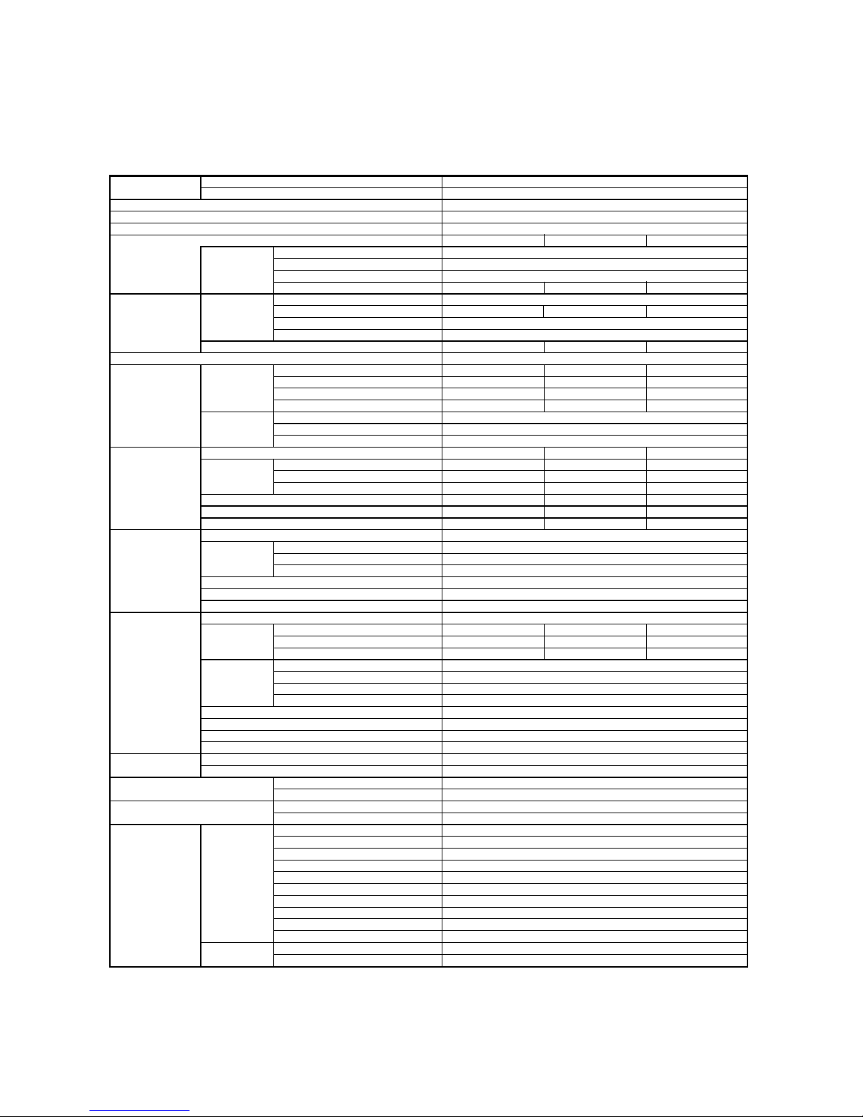
1. SPECIFICATIONS
1-1. Specifications
• For performance when each indoor unit is combined with other unit, ref er to the separate table .
• The specifications may be subject to change without notice f or purpose of improvement.
RAS-M10UKCV-E, RAS-M13UKCV-E, RAS-M16UKCV-E
RAS-3M23YACV-E
6,7
2,2~7,0
220–240V–1Ph–50Hz
220V 230V 240V
RAS-M10UKCV-E, RAS-M13UKCV-E, RAS-M16UKCV-E
0,15
30
91 87 83
RAS-3M23YACV-E
9,84 9,39 8,98
2060
95
10,29 9,84 9,43
3,12
RAS-M10UKCV-E RAS-M13UKCV-E RAS-M16UKCV-E
36 39 42
33 35 39
28 28 33
RAS-3M23YACV-E
45
48
RAS-M10UKCV-E RAS-M13UKCV-E RAS-M16UKCV-E
275275275
790 790 790
208 208 208
10 10 10
19 19 19
470 520 600
RAS-3M23YACV-E
695
780
270
48
40
2100
Flare connection
RAS-M10UKCV-E RAS-M13UKCV-E RAS-M16UKCV-E
Ø6,35 Ø6,35 Ø6,35
Ø9,52 Ø9,52 Ø12,7
RAS-3M23YACV-E
Ø6,35 / Ø12,7
Ø6,35 / Ø9,52
Ø6,35 / Ø9,52
20
40
40
10
R410A
1,5
3 Wires : includes earth
4 Wires : includes earth
21–32
10–43
1
1
1
1
2 (Ø3,1 x 16L)
1
1
2
6 (Ø4 x 25L)
1
1
1
Unit model Indoor
Outdoor
Cooling capacity (kW)
Cooling capacity range (kW)
Power supply
Electric
characteristics
Indoor Unit model
Running current (A)
Power consumption (W)
Power factor (%)
Outdoor Unit model
Running current (A)
Power consumption (W)
Power factor (%)
Starting current (A)
COP
Operating noise Indoor Unit model
High (dB•A)
Medium (dB•A)
Low (dB•A)
Outdoor Unit model
10-1 unit operating (dB•A)
3 units operating (dB•A)
Indoor unit Unit model
Dimension Height (mm)
Width (mm)
Depth (mm)
Net weight (kg)
Fan motor output (W)
Air flow rate (m³/h)
Outdoor unit Unit model
Dimension Height (mm)
Width (mm)
Depth (mm)
Net weight (kg)
Fan motor output (W)
Air flow rate (m³/h)
Piping connection Type
Indoor unit Unit model
Liquid side
Gas side
Outdoor unit Unit model
A unit
B unit
C unit
Maximum length (per unit) (m)
Maximum length (total) (m)
Maximum chargeless length (m)
Maximum height difference (m)
Refrigerant Name of refrigerant
Weight (kg)
Wiring connection Power supply
Interconnection
Usable temperature range Indoor (°C)
Outdoor (°C)
Accessory Indoor unit Installation plate
Wireless remote control
Label
Remote control holder
Pan head wood screw
Purifying filter
Zeodorizing filter
Batteries
Mounting screw
Installation manual
Outdoor unit Installation manual
Owner's manual

– 4 –
• The above specification values are those under the conditions that the indoor DB/WB=27/19°C and the
outdoor DB=35°C.
• Indoor unit 10 : RAS-M10UKCV-E, 13 : RAS-M13UKCV-E, 16 : RAS-M16UKCV-E
Operating
Power
status
supply
(V)
1 unit 220
230
240
220
230
240
220
230
240
2 units 220
230
240
220
230
240
220
230
240
220
230
240
220
230
240
220
230
240
3 units 220
230
240
220
230
240
220
230
240
220
230
240
Indoor unit Unit capacity (kW)
ABCABC
10 — — 2,7 — —
10 — — 2,7 — —
10 — — 2,7 — —
13 — — 3,7 — —
13 — — 3,7 — —
13 — — 3,7 — —
16 — — 4,5 — —
16 — — 4,5 — —
16 — — 4,5 — —
10 10 — 2,7 2,7 —
10 10 — 2,7 2,7 —
10 10 — 2,7 2,7 —
10 13 — 2,45 3,35 —
10 13 — 2,45 3,35 —
10 13 — 2,45 3,35 —
10 16 — 2,21 3,69 —
10 16 — 2,21 3,69 —
10 16 — 2,21 3,69 —
13 13 — 2,95 2,95 —
13 13 — 2,95 2,95 —
13 13 — 2,95 2,95 —
13 16 — 2,71 3,29 —
13 16 — 2,71 3,29 —
13 16 — 2,71 3,29 —
16 16 — 3,05 3,05 —
16 16 — 3,05 3,05 —
16 16 — 3,05 3,05 —
10 10 10 2,13 2,13 2,13
10 10 10 2,13 2,13 2,13
10 10 10 2,13 2,13 2,13
10 10 13 1,99 1,99 2,72
10 10 13 1,99 1,99 2,72
10 10 13 1,99 1,99 2,72
10 13 13 1,80 2,45 2,45
10 13 13 1,80 2,45 2,45
10 13 13 1,80 2,45 2,45
10 10 16 1,83 1,83 3,04
10 10 16 1,83 1,83 3,04
10 10 16 1,83 1,83 3,04
Cooling Power Operation Outdoor
capacity consumption current noise
(kW) (W) (A) (dB)
2,7 770 4,12 45
(1,4 to 3,2) (320 to 950) (2,08 to 5,08)
2,7 770 3,94 45
(1,4 to 3,2) (320 to 950) (1,99 to 4,86)
2,7 770 3,77 45
(1,4 to 3,2) (320 to 950) (1,90 to 4,66)
3,7 1200 6,34 48
(1,4 to 4,4) (320 to 1470) (2,08 to 7,51)
3,7 1200 6,07 48
(1,4 to 4,4) (320 to 1470) (1,99 to 7,18)
3,7 1200 5,81 48
(1,4 to 4,4) (320 to 1470) (1,90 to 6,88)
4,5 1600 7,66 48
(1,4 to 4,9) (320 to 1750) (2,08 to 8,37)
4,5 1600 7,32 48
(1,4 to 4,9) (320 to 1750) (1,99 to 8,01)
4,5 1600 7,02 48
(1,4 to 4,9) (320 to 1750) (1,90 to 7,68)
5,4 1500 7,18 48
(1,8 to 6,0) (360 to 1880) (2,34 to 9,00)
5,4 1500 6,86 48
(1,8 to 6,0) (360 to 1880) (2,24 to 8,60)
5,4 1500 6,58 48
(1,8 to 6,0) (360 to 1880) (2,14 to 8,25)
5,8 1800 8,61 48
(1,8 to 6,3) (360 to 1970) (2,34 to 9,43)
5,8 1800 8,24 48
(1,8 to 6,3) (360 to 1970) (2,24 to 9,02)
5,8 1800 7,89 48
(1,8 to 6,3) (360 to 1970) (2,14 to 8,64)
5,9 1830 8,76 48
(1,8 to 6,4) (360 to 2000) (2,34 to 9,57)
5,9 1830 8,38 48
(1,8 to 6,4) (360 to 2000) (2,24 to 9,15)
5,9 1830 8,03 48
(1,8 to 6,4) (360 to 2000) (2,14 to 8,77)
5,9 1830 8,76 48
(1,8 to 6,4) (360 to 2000) (2,34 to 9,57)
5,9 1830 8,38 48
(1,8 to 6,4) (360 to 2000) (2,24 to 9,15)
5,9 1830 8,03 48
(1,8 to 6,4) (360 to 2000) (2,14 to 8,77)
6,0 1850 8,85 48
(1,8 to 6,4) (360 to 2000) (2,34 to 9,57)
6,0 1850 8,50 48
(1,8 to 6,4) (360 to 2000) (2,24 to 9,15)
6,0 1850 8,11 48
(1,8 to 6,4) (360 to 2000) (2,14 to 8,77)
6,1 1870 8,95 48
(1,8 to 6,5) (360 to 2050) (2,34 to 9,81)
6,1 1870 8,56 48
(1,8 to 6,5) (360 to 2050) (2,24 to 9,38)
6,1 1870 8,20 48
(1,8 to 6,5) (360 to 2050) (2,14 to 8,99)
6,4 1880 9,00 48
(2,2 to 7,0) (420 to 2300) (2,73 to 11,0)
6,4 1880 8,60 48
(2,2 to 7,0) (420 to 2300) (2,61 to 10,53)
6,4 1880 8,25 48
(2,2 to 7,0) (420 to 2300) (2,50 to 10,09)
6,7 2150 10,29 48
(2,2 to 7,0) (420 to 2300) (2,73 to 11,0)
6,7 2150 9,84 48
(2,2 to 7,0) (420 to 2300) (2,61 to 10,53)
6,7 2150 9,43 48
(2,2 to 7,0) (420 to 2300) (2,50 to 10,09)
6,7 2150 10,29 48
(2,2 to 7,0) (420 to 2300) (2,73 to 11,0)
6,7 2150 9,84 48
(2,2 to 7,0) (420 to 2300) (2,61 to 10,53)
6,7 2150 9,43 48
(2,2 to 7,0) (420 to 2300) (2,50 to 10,09)
6,7 2150 10,29 48
(2,2 to 7,0) (420 to 2300) (2,73 to 11,0)
6,7 2150 9,84 48
(2,2 to 7,0) (420 to 2300) (2,61 to 10,53)
6,7 2150 9,43 48
(2,2 to 7,0) (420 to 2300) (2,50 to 10,09)
1-2.
Specifications of Performance When Each Indoor Unit is Combined with Other Unit
– 5 –
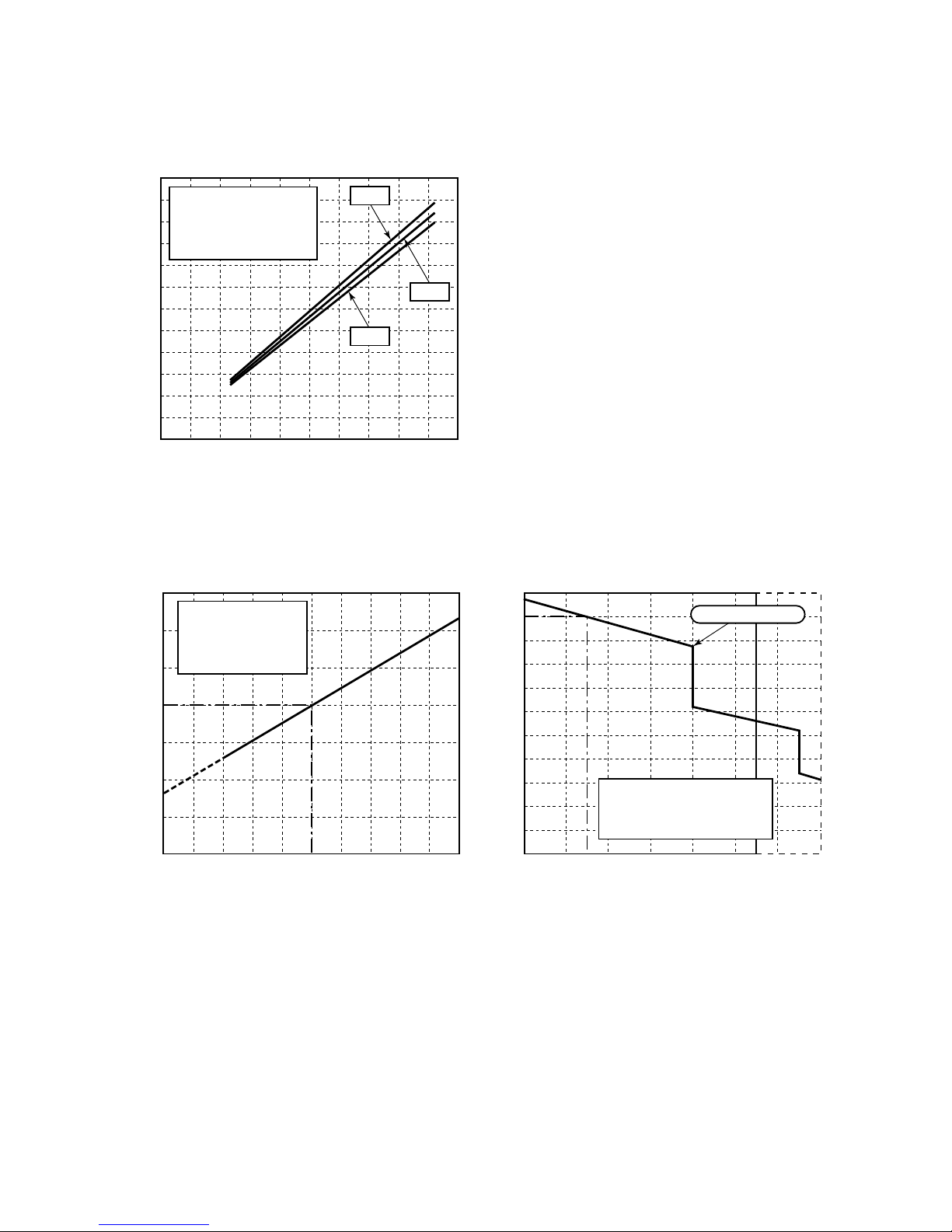
1-2-2. Capacity Variation Ratio According to Temperature
1-2-1. Operation Characteristic Curve
12
11
10
9
8
7
6
5
4
3
2
1
0
100 2030405060708090100
Inverter output frequency (rps)
Current (A)
• Conditions
Indoor : DB27˚C/WB19˚C
Outdoor : DB35˚C
Air flow : High
Pipe length 5m × 3
3 units operating
220V
240V
230V
105115
110
100
105
100
95
90
85
0
95
90
85
80
75
70
65
60
55
50
32 34 36 38 40 42 44 4614 16
4318 20 22 24
Outdoor temp. (˚C)
* Capacity ratio : 100% = 6,7 kW
Indoor air wet bulb temp. (˚C)
Capacity ratio (%)
Capacity ratio (%)
• Conditions
Indoor : DB27˚C
Outdoor : DB35˚C
Indoor air flow: High
Pipe length 5m × 3
3 units operating
• Conditions
Indoor : DB27˚C/WB19˚C
Indoor air flow: High
Pipe length 5m × 3
3 units operating
Current Limited Start
– 6 –
DB WB
Indoor temp. °C 27 19
Outdoor temp. °C 35 —
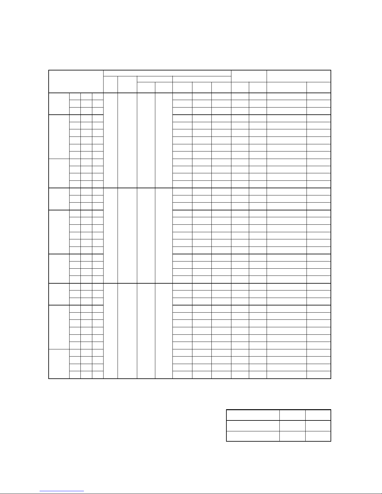
NOTE :
Model of Indoor unit 10 : RAS-M10UKCV-E, 13 : RAS-M13UKCV-E, 16 : RAS-M16UKCV-E
MCA : Minimum Circuit Amps .
ICF : Maximum Instantaneous Current Flow
(Equivalent to MCA in case of inverter air conditioner)
MOCP : Maximum Ov ercurrent Protection (Fuse only)
MSC : Maximum Starting Current
FLA : Full Load Amps.
RLA : Rated Load Amps. RLA under conditions on the right.
Combination of
indoor unit operation
1 unit 10 — —
13 — —
16 — —
2 units 10 10 —
13 10 —
16 10 —
13 13 —
16 13 —
16 16 —
3 units 10 10 10
13 10 10
13 13 10
16 10 10
1 unit 10 — —
13 — —
16 — —
2 units 10 10 —
13 10 —
16 10 —
13 13 —
16 13 —
16 16 —
3 units 10 10 10
13 10 10
13 13 10
16 10 10
1 unit 10 — —
13 — —
16 — —
2 units 10 10 —
13 10 —
16 10 —
13 13 —
16 13 —
16 16 —
3 units 10 10 10
13 10 10
13 13 10
16 10 10
System
Voltage range Power supply
Hz
Volts-
Min. Max. MCA ICF
MOCP
Ph.
(Amps)
4,99 4,99 8,46
7,76 7,76 13,45
9,41 9,41 16,42
8,78 8,78 15,16
10,56 10,56 18,37
50 220-1 198 264
10,75 10,75 18,71
10,75 10,75 18,71
10,86 10,86 18,91
10,99 10,99 19,14
11,01 11,01 19,06
12,63 12,63 21,97
12,63 12,63 21,97
12,63 12,63 21,97
4,76 4,76 8,05
7,43 7,43 12,85
8,99 8,99 15,66
8,38 8,38 14,44
10,10 10,10 17,54
50 230-1 198 264
10,28 10,28 17,86
10,28 10,28 17,86
10,43 10,43 18,13
10,50 10,50 18,26
10,51 10,51 18,16
12,06 12,06 20,95
12,06 12,06 20,95
12,06 12,06 20,95
4,55 4,55 7,67
7,10 7,10 12,26
8,61 8,61 14,98
8,03 8,03 13,81
9,66 9,66 16,75
50 240-1 198 264
9,84 9,84 17,07
9,84 9,84 17,07
9,94 9,94 17,25
10,05 10,05 17,45
10,08 10,08 17,38
11,55 11,55 20,03
11,55 11,55 20,03
11,55 11,55 20,03
Compressor Fan motor FLA
MSC RLA Indoor Outdoor
3,47 3,47 0,15 x 1 = 0,15 0,5
5,69 5,69 0,15 x 1 = 0,15 0,5
7,01 7,01 0,15 x 1 = 0,15 0,5
6,38 6,38 0,15 x 2 = 0,30 0,5
7,81 7,81 0,15 x 2 = 0,30 0,5
7,96 7,96 0,15 x 2 = 0,30 0,5
7,96 7,96 0,15 x 2 = 0,30 0,5
8,05 8,05 0,15 x 2 = 0,30 0,5
8,15 8,15 0,15 x 2 = 0,30 0,5
8,05 8,05 0,15 x 3 = 0,45 0,5
9,34 9,34 0,15 x 3 = 0,45 0,5
9,34 9,34 0,15 x 3 = 0,45 0,5
9,34 9,34 0,15 x 3 = 0,45 0,5
3,29 3,29 0,15 x 1 = 0,15 0,5
5,42 5,42 0,15 x 1 = 0,15 0,5
6,67 6,67 0,15 x 1 = 0,15 0,5
6,06 6,06 0,15 x 2 = 0,30 0,5
7,44 7,44 0,15 x 2 = 0,30 0,5
7,58 7,58 0,15 x 2 = 0,30 0,5
7,58 7,58 0,15 x 2 = 0,30 0,5
7,70 7,70 0,15 x 2 = 0,30 0,5
7,76 7,76 0,15 x 2 = 0,30 0,5
7,65 7,65 0,15 x 3 = 0,45 0,5
8,89 8,89 0,15 x 3 = 0,45 0,5
8,89 8,89 0,15 x 3 = 0,45 0,5
8,89 8,89 0,15 x 3 = 0,45 0,5
3,12 3,12 0,15 x 1 = 0,15 0,5
5,16 5,16 0,15 x 1 = 0,15 0,5
6,37 6,37 0,15 x 1 = 0,15 0,5
5,78 5,78 0,15 x 2 = 0,30 0,5
7,09 7,09 0,15 x 2 = 0,30 0,5
7,23 7,23 0,15 x 2 = 0,30 0,5
7,23 7,23 0,15 x 2 = 0,30 0,5
7,31 7,31 0,15 x 2 = 0,30 0,5
7,40 7,40 0,15 x 2 = 0,30 0,5
7,30 7,30 0,15 x 3 = 0,45 0,5
8,48 8,48 0,15 x 3 = 0,45 0,5
8,48 8,48 0,15 x 3 = 0,45 0,5
8,48 8,48 0,15 x 3 = 0,45 0,5
1-3. Electrical Data

– 7 –
2. REFRIGERANT R410A
(5) After completion of installation work, check to
make sure that there is no refrigeration gas
leakage.
If the refrigerant gas leaks into the room, coming
into contact with fire in the fan-driven heater ,
space heater, etc., a poisonous gas ma y occur.
(6) When an air conditioning system charged with a
large volume of refrigerant is installed in a small
room, it is necessary to exercise care so that,
even when refrigerant leaks, its concentration
does not exceed the marginal lev el.
If the refrigerant gas leakage occurs and its
concentration exceeds the marginal lev el, an
oxygen starvation accident may result.
(7) Be sure to carry out installation or removal
according to the installation manual.
Improper installation may cause refrigeration
trouble, water leakage, electric shoc k, fire , etc.
(8) Unauthorized modifications to the air conditioner
may be dangerous. If a breakdown occurs
please call a qualified air conditioner technician
or electrician.
Improper repair’s may result in w ater leakage ,
electric shock and fire, etc.
2-2. Refrigerant Piping Installation
2-2-1. Piping Materials and Joints Used
For the refrigerant piping installation, copper pipes
and joints are mainly used. Copper pipes and joints
suitable for the refrigerant must be chosen and
installed. Furthermore, it is necessary to use clean
copper pipes and joints whose interior surfaces are
less affected by contaminants.
(1) Copper Pipes
It is necessary to use seamless copper pipes
which are made of either copper or copper alloy
and it is desirable that the amount of residual oil
is less than 40 mg/10 m. Do not use copper
pipes having a collapsed, deformed or discolored portion (especially on the interior surface).
Otherwise, the expansion valv e or capillary tube
may become block ed with contaminants.
As an air conditioner using R410A incurs
pressure higher than when using R22, it is
necessary to choose adequate materials.
Thicknesses of copper pipes used with R410A
are as shown in Table 2-2-1. Ne ver use copper
pipes thinner than 0,8 mm even when it is
available on the mark et.
This air conditioner adopts the new refrigerant HFC
(R410A) which does not damage the ozone layer.
The working pressure of the new refrigerant R410A
is 1,6 times higher than conventional refrigerant
(R22). The refrigerating oil is also changed in
accordance with change of refrigerant, so be careful
that water, dust, and e xisting refrigerant or refrigerating oil are not entered in the refrigerant cycle of the
air conditioner using the new refrigerant during
installation work or servicing time.
The next section describes the precautions for air
conditioner using the new refrigerant. Conf orming to
contents of the next section together with the
general cautions included in this manual, perform
the correct and safe work.
2-1. Safety During Installation/Servicing
As R410A’s pressure is about 1,6 times higher than
that of R22, improper installation/servicing may
cause a serious trouble. By using tools and materials exclusive f or R410A, it is necessary to carry out
installation/servicing safely while taking the following
precautions into consideration.
(1) Never use refrigerant other than R410A in an air
conditioner which is designed to operate with
R410A.
If other refrigerant than R410A is mixed, pressure in the refrigeration cycle becomes abnormally high, and it may cause personal injury, etc.
by a rupture.
(2) Confirm the used refrigerant name, and use
tools and materials exclusive for the refriger ant
R410A.
The refrigerant name R410A is indicated on the
visible place of the outdoor unit of the air conditioner using R410A as refrigerant. To prevent
mischarging, the diameter of the service port
differs from that of R22.
(3) If a refrigeration gas leakage occurs during
installation/servicing, be sure to ventilate fully .
If the refrigerant gas comes into contact with fire,
a poisonous gas may occur .
(4) When installing or removing an air conditioner,
do not allow air or moisture to remain in the
refrigeration cycle. Otherwise , pressure in the
refrigeration cycle may become abnormally high
so that a rupture or personal injury may be
caused.
– 8 –
(2) Joints
For copper pipes, flare joints or soc k et joints are
used. Prior to use, be sure to remove all contaminants.
a) Flare Joints
Flare joints used to connect the copper pipes
cannot be used for pipings whose outer
diameter exceeds 20 mm. In such a case,
socket joints can be used.
Sizes of flare pipe ends, flare joint ends and
flare nuts are as shown in Tables 2-2-3 ~ 2-2-6
below .
b) Socket Joints
Socket joints are such that they are br azed
for connections, and used mainly for thick
pipings whose diameter is larger than 20 mm.
Thicknesses of socket joints are as sho wn in
T ab le 2-2-2.
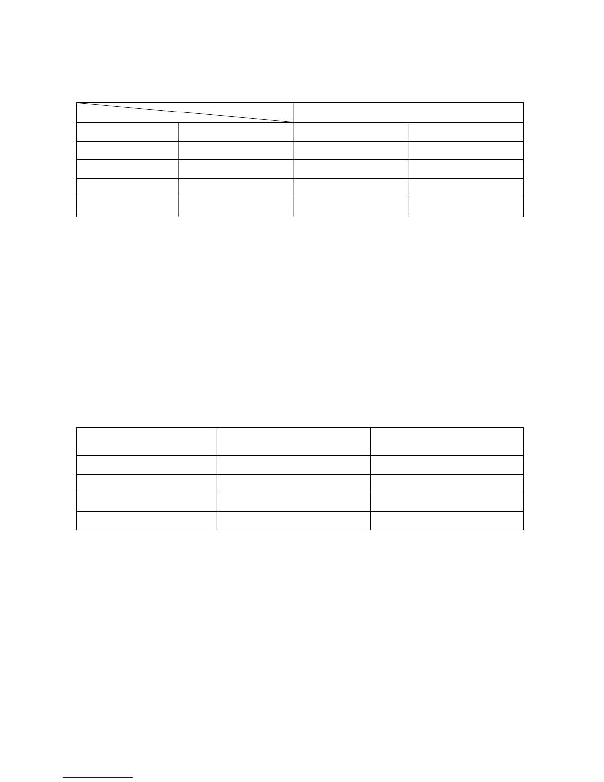
T able 2-2-2 Minimum thicknesses of socket joints
Nominal diameter
Reference outer diameter of Minimum joint thickness
copper pipe jointed (mm) (mm)
1/4 6,35 0,50
3/8 9,52 0,60
1/2 12,70 0,70
5/8 15,88 0,80
2-2-2. Processing of Piping Materials
When performing the refrigerant piping installation,
care should be taken to ensure that water or dust
does not enter the pipe interior, that no other oil
other than lubricating oils used in the installed air
conditioner is used, and that refrigerant does not
leak. When using lubricating oils in the piping
processing, use such lubricating oils whose water
content has been removed. When stored, be sure to
seal the container with an airtight cap or any other
cover.
(1) Flare Processing Procedures and Precautions
a) Cutting the Pipe
By means of a pipe cutter, slowly cut the pipe
so that it is not deformed.
b) Removing Burrs and Chips
If the flared section has chips or burrs,
refrigerant leakage may occur . Carefully
remove all burrs and clean the cut surface
before installation.
T a ble 2-2-1 Thicknesses of annealed copper pipes
Thickness (mm)
Nominal diameter Outer diameter (mm) R410A R22
1/4 6,35 0,80 0,80
3/8 9,52 0,80 0,80
1/2 12,70 0,80 0,80
5/8 15,88 1,00 1,00
– 9 –
A
ØD
Flare nut
width
(mm)
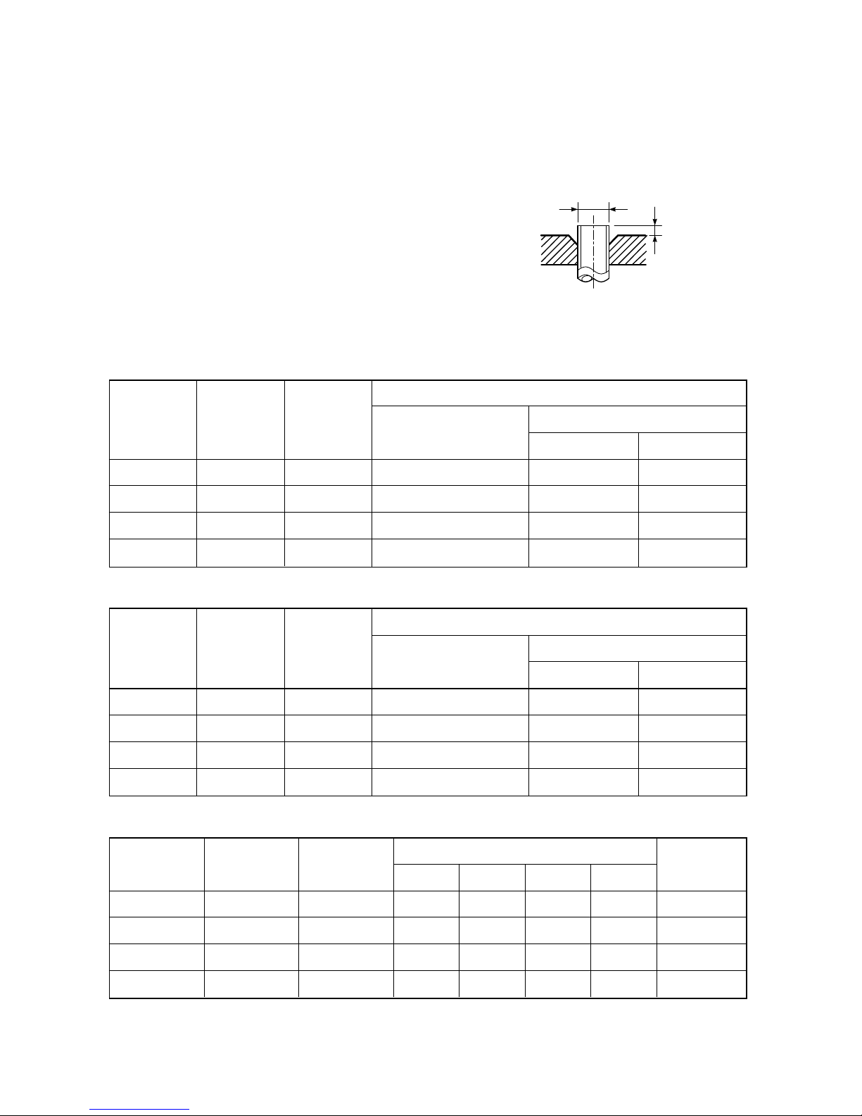
Flare processing dimensions differ according
to the type of flare tool. When using a conventional flare tool, be sure to secure “dimension A” by using a gauge for size adjustment.
Fig. 2-2-1 Flare processing dimensions
T able 2-2-3 Dimensions related to flare pr ocessing for R410A
Nominal
Outer
Thickness
diameter
diameter
(mm)
(mm)
1/4 6,35 0,8
3/8 9,52 0,8
1/2 12,70 0,8
5/8 15,88 1,0
A (mm)
Flare tool for
Conventional flare tool
R410A clutch type
Clutch type Wing nut type
0 to 0,5 1,0 to 1,5 1,5 to 2,0
0 to 0,5 1,0 to 1,5 1,5 to 2,0
0 to 0,5 1,0 to 1,5 2,0 to 2,5
0 to 0,5 1,0 to 1,5 2,0 to 2,5
Table 2-2-4 Dimensions related to flare processing for R22
Nominal
Outer
Thickness
diameter
diameter
(mm)
(mm)
1/4 6,35 0,8
3/8 9,52 0,8
1/2 12,70 0,8
5/8 15,88 1,0
A (mm)
Flare tool for
Conventional flare tool
R22 clutch type
Clutch type Wing nut type
0 to 0,5 0,5 to 1,0 1,0 to 1,5
0 to 0,5 0,5 to 1,0 1,0 to 1,5
0 to 0,5 0,5 to 1,0 1,5 to 2,0
0 to 0,5 0,5 to 1,0 1,5 to 2,0
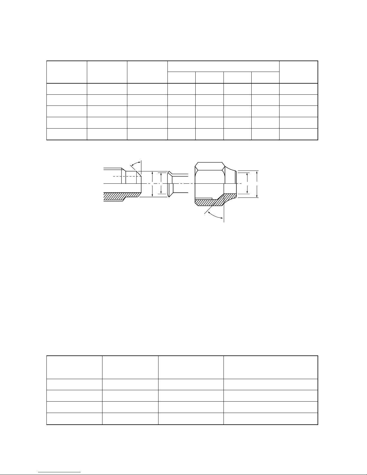
T able 2-2-5 Flare and flare nut dimensions for R410A
Nominal Outer diameter Thickness
diameter (mm) (mm)
1/4 6,35 0,8
3/8 9,52 0,8
1/2 12,70 0,8
5/8 15,88 1,0
Dimension (mm)
ABCD
9,1 9,2 6,5 13 17
13,2 13,5 9,7 20 22
16,6 16,0 12,9 23 26
19,7 19,0 16,0 25 29
c) Insertion of Flare Nut
d) Flare Processing
Make certain that a clamp bar and copper
pipe have been cleaned.
By means of the clamp bar, perform the flare
processing correctly .
Use either a flare tool for R410A or conventional flare tool.
– 10 –
43˚
~
45˚
45˚
~
46˚
B A
C
D
Flare nut
width
(mm)
Nominal Outer diameter Thickness
diameter (mm) (mm)
1/4 6,35 0,8
3/8 9,52 0,8
1/2 12,70 0,8
5/8 15,88 1,0
3/4 19,05 1,0
Dimension (mm)
ABCD
9,0 9,2 6,5 13 17
13,0 13,5 9,7 20 22
16,2 16,0 12,9 20 24
19,4 19,0 16,0 23 27
23,3 24,0 19,2 34 36
Fig. 2-2-2 Relations between flare nut and flare seal surface
(2) Flare Connecting Procedures and Precautions
a) Make sure that the flare and union portions
do not have any scar or dust, etc.
b) Correctly align the processed flare surface
with the union axis.
c) Tighten the flare with designated torque by
means of a torque wrench. The tightening
torque for R410A is the same as that for
conventional R22. Incidentally , when the
torque is weak, the gas leakage may occur .
When it is strong, the flare nut may crack and
may be made non-removab le . When choosing the tightening torque, comply with values
designated by manufacturers. Table 2-2-7
shows reference values.
Note:
When applying oil to the flare surface, be sure to use
oil designated by the manufacturer. If any other oil is
used, the lubricating oils may deteriorate and cause
the compressor to burn out.
Table 2-2-7 Tightening tor que of flare f or R410A [Reference v alues]
Nominal Outer diameter Tightening torque
Tightening torque of torque
wrenches available on the market
diameter (mm) N•m (kgf•cm)
N•m (kgf•cm)
1/4 6,35 14 to 18 (140 to 180) 16 (160), 18 (180)
3/8 9,52 33 to 42 (330 to 420) 42 (420)
1/2 12,70 50 to 62 (500 to 620) 55 (550)
5/8 15,88 63 to 77 (630 to 770) 65 (650)
T able 2-2-6 Flare and flare nut dimensions for R22
– 11 –
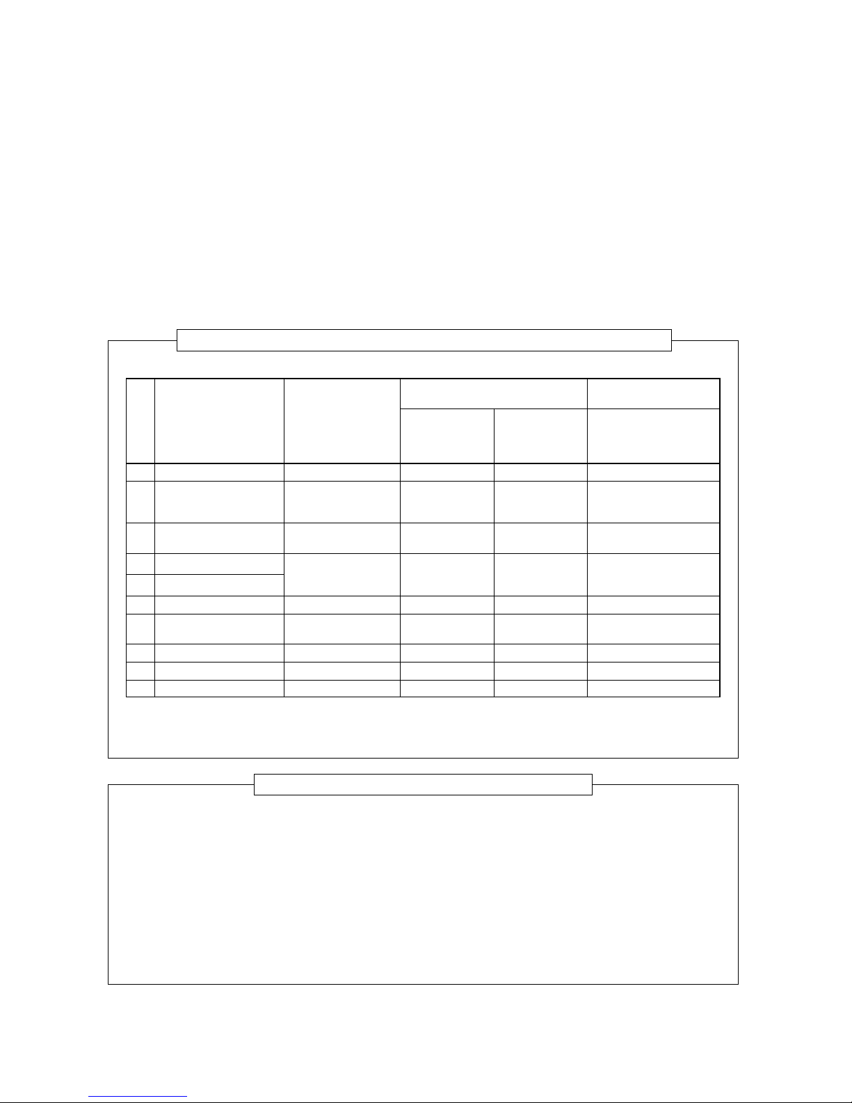
Tools exclusive for R410A (The following tools for R410A are required.)
Tools whose specifications are changed for R410A and their interchangeability
No. Used tool
Flare tool
Copper pipe gauge for
adjusting projection
margin
Torque wrench
(For Ø12,7)
Gauge manifold
Charge hose
Vacuum pump adapter
Electronic balance for
refrigerant charging
Refr igerant cylinder
Leakage detector
Charging cylinder
Usage
Pipe flaring
Flaring by
conventional flare
tool
Connection of flare
nut
Evacuating, refrigerant charge, run
check, etc.
Vacuum evacuating
Refrigerant charge
Refrigerant charge
Gas leakage check
Refrigerant charge
R410A air conditioner
installation
Existence of Whether
new equipment conventional
for R410A equipment can
be used
Yes
*
(Note 1)
Yes
*
(Note 1)
Yes
X
Yes
X
Yes
X
Yes
X
Yes
X
Yes
X
(Note 2)
X
Conventional air
conditioner installation
Whether new equipment can be used with
conventional refrigerant
¡
*
(Note 1)
X
X
¡
¡
X
¡
X
(Note 1) When flaring is carried out for R410A using the con v entional flare tools , adjustment of projection
margin is necessary. For this adjustment, a copper pipe gauge, etc. are necessary .
(Note 2) Charging cylinder for R410A is being currently developed.
General tools (Conventional tools can be used.)
In addition to the above exclusiv e tools , the following equipments which serve also for R22 are necessary
as the general tools.
(1) Vacuum pump
Use vacuum pump by
attaching vacuum pump adapter.
(2) Torque wrench (For Ø6,35)
(3) Pipe cutter
(4) Reamer
(5) Pipe bender
(6) Level vial
(7) Screwdriver (+, –)
(8) Spanner or Monkey wrench
(9) Hole core drill (Ø65)
(10) Hexagon wrench
(Opposite side 5mm)
(11) Tape measure
(12) Metal saw
Also prepare the following equipments for other installation method and run chec k.
(1) Clamp meter
(2) Thermometer
(3) Insulation resistance tester
(4) Electroscope
2-3. Tools
2-3-1. Required T ools
The service port diameter of pac ked valv e of the outdoor unit in the air conditioner using R410A is changed to prev ent
mixing of other refrigerant. To reinforce the pressure-resisting strength, flare processing dimensions and opposite side
dimension of flare nut (For Ø12,7 copper pipe) of the refrigerant piping are lengthened.
The used refrigerating oil is changed, and mixing of oil may cause a trouble such as generation of sludge,
clogging of capillary, etc. Accordingly, the tools to be used are classified into the following three types.
(1) T ools e xclusive for R410A (Those which cannot be used for conventional refrigerant (R22))
(2) T ools e xclusive for R410A, but can be also used for con v entional refrigerant (R22)
(3) T ools commonly used f or R410A and for conventional refrigerant (R22)
The table below shows the tools exclusiv e for R410A and their interchangeability .
– 12 –
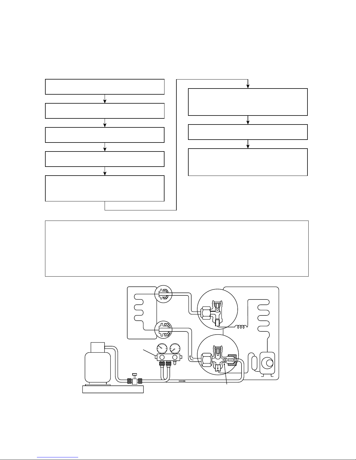
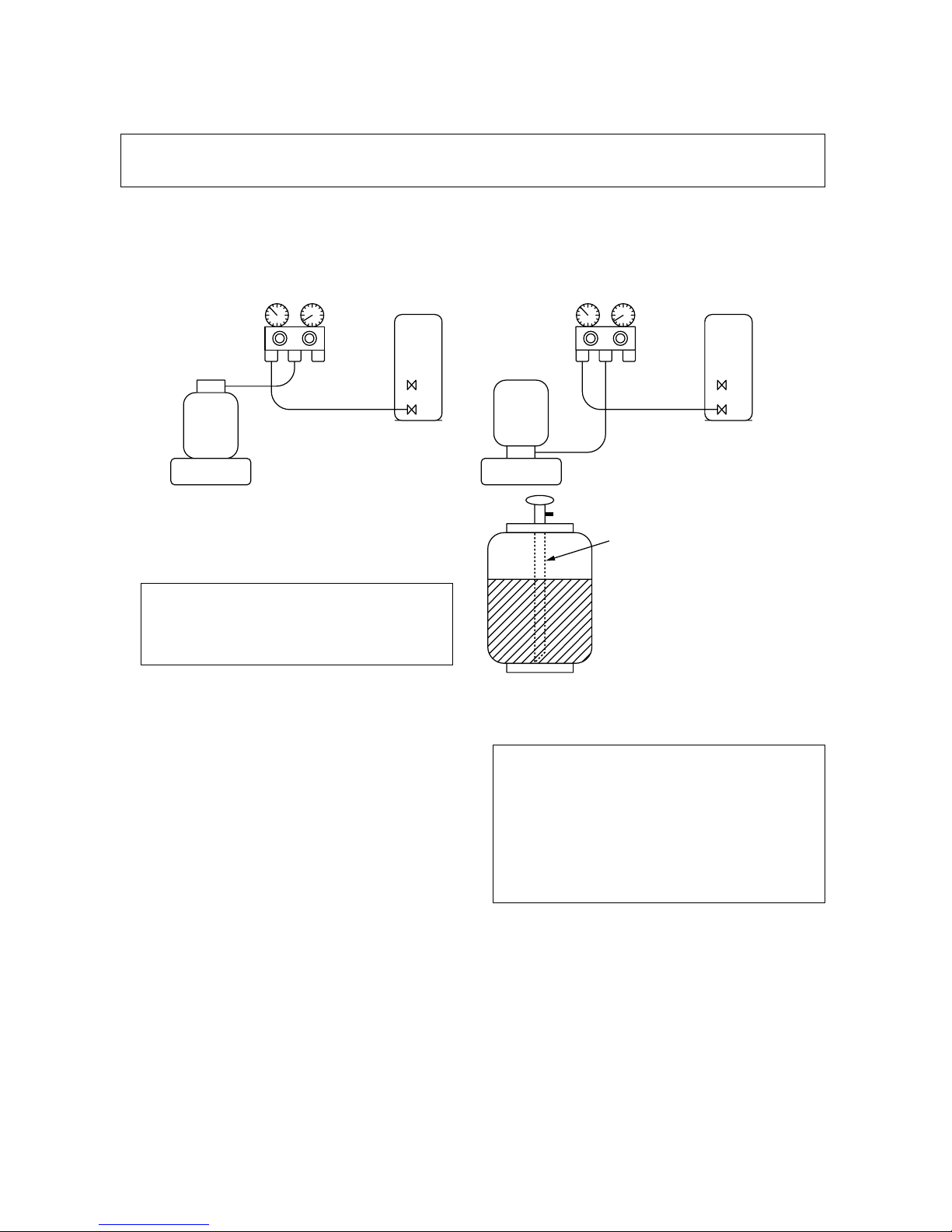
(INDOOR unit)
(Liquid side)
Refrigerant cylinder
(With siphon pipe)
Check valve
(Gas side)
Open/Close valve
for charging
Electronic balance for refrigerant charging
Opened
(OUTDOOR unit)
Closed
Service port
Connect the charge hose to packed valve service
port at the outdoor unit’s gas side.
Recover the refrigerant, and check no refrigerant
remains in the equipment.
(For refrigerant charging, see the figure below.)
Connect the charge hose of the vacuum pump
adapter.
Open fully both packed valves at liquid and gas
sides.
Place the handle of the gauge manifold Low in the
fully opened position, and turn on the vacuum pump’s
power switch. Then, evacuating the refrigerant in the
cycle.
When the compound gauge’s pointer has indicated
–0,1 Mpa (–76 cmHg), place the handle Low in the
fully closed position, and turn off the vacuum pump’s
power switch.
Keep the status as it is for 1 to 2 minutes, and ensure
that the compound gauge’s pointer does not return.
Set the refrigerant cylinder to the electronic balance,
connect the connecting hose to the cylinder and the
connecting port of the electronic balance, and charge
liquid refrigerant.
Never charge refrigerant e xceeding the specified amount.
If the specified amount of refrigerant cannot be charged, charge refrigerant bit by bit in COOL mode.
Do not carry out additional charging.
When additional charging is carried out if refrigerant leaks, the refrigerant composition changes in the
refrigeration cycle, that is characteristics of the air conditioner changes, refrigerant exceeding the specified amount is charged, and working pressure in the refrigeration cycle becomes abnormally high pressure, and may cause a rupture or personal injury .
Fig. 2-4-1 Configuration of refrigerant charging
2-4. Recharging of Refrigerant
When it is necessary to recharge refrigerant, charge the specified amount of new refrigerant according to the
following steps.
– 13 –
Gauge manifold
[ Cylinder with siphon ] [ Cylinder without siphon ]
OUTDOOR unit
Gauge manifold
OUTDOOR unit
Refrigerant
cylinder
Electronic
balance
Refrigerant
cylinder
Electronic
balance
Siphon
It is necessary for charging refrigerant under condition of liquid because R410A is mixed type of refrigerant.
Accordingly , when charging refrigerant from the refrigerant cylinder to the equipment, charge it turning the
cylinder upside down if cylinder is not equipped with siphon.
R410A refrigerant is HFC mixed refrigerant.
Therefore, if it is charged with gas, the composition of the charged refrigerant changes and
the characteristics of the equipment varies.
Fig. 2-4-2
2-5. Brazing of Pipes
2-5-1. Materials for Brazing
(1) Silver brazing filler
Silver brazing filler is an alloy mainly composed
of silver and copper. It is used to join iron,
copper or copper alloy, and is relatively expensive though it excels in solderability.
(2) Phosphor bronze brazing filler
Phosphor bronze brazing filler is generally used
to join copper or copper alloy.
(3) Low temperature brazing filler
Low temperature brazing filler is generally called
solder, and is an allo y of tin and lead. Since it is
weak in adhesive strength, do not use it for
refrigerant pipes.
Phosphor bronze brazing filler tends to react
with sulfur and produce a fragile compound
water solution, which may cause a gas leakage. Therefore, use an y other type of brazing
filler at a hot spring resort, etc., and coat the
surface with a paint.
When performing brazing again at time of
servicing, use the same type of brazing filler.
2-5-2. Flux
(1) Reason why flux is necessary
• By removing the oxide film and any f oreign
matter on the metal surface, it assists the flow
of brazing filler.
• In the brazing process, it prevents the metal
surface from being oxidiz ed.
• By reducing the brazing filler’s surface tension,
the brazing filler adheres better to the treated
metal.
Be sure to make setting so that liquid can be charged.
When using a cylinder equipped with a siphon, liquid can be charged without turning it upside down.
– 14 –
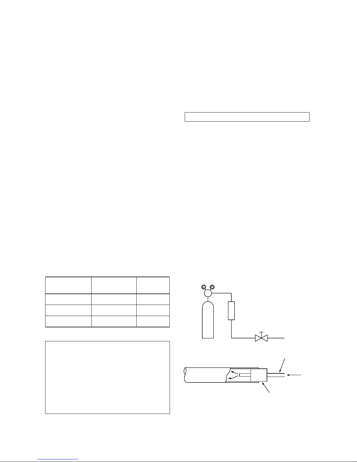
Nitrogen gas
cylinder
Pipe
Flow meter
M
Stop valve
From Nitrogen cylind
er
Nitrogen
gas
Rubber plug
Piping
material
Copper - Copper
Copper - Iron
Iron - Iron
Used brazing Used
filler flux
Phosphor copper Do not use
Silver Paste flux
Silver Vapor flux
Do not enter flux into the refrigeration cycle.
When chlorine contained in the flux remains
within the pipe, the lubricating oil deteriorates. Therefore, use a flux which does not
contain chlorine.
When adding water to the flux, use water
which does not contain chlorine (e.g. distilled
water or ion-exchange water).
Remove the flux after brazing.
2-5-3. Brazing
As brazing work requires sophisticated techniques,
experiences based upon a theoretical knowledge, it
must be performed by a person qualified.
In order to prevent the oxide film from occurring in
the pipe interior during brazing, it is effective to
proceed with brazing while letting dry Nitrogen gas
(N2) flow .
Never use gas other than Nitrogen gas.
(1) Brazing method to prevent oxidation
Attach a reducing valve and a flow-meter to
the Nitrogen gas cylinder.
Use a copper pipe to direct the piping
material, and attach a flow-meter to the
cylinder.
Apply a seal onto the clearance between the
piping material and inserted copper pipe for
Nitrogen in order to prevent backflo w of the
Nitrogen gas.
When the Nitrogen gas is flowing, be sure to
keep the piping end open.
Adjust the flow rate of Nitrogen gas so that it
is lower than 0,05 m
3
/Hr or 0,02 MPa (0,2kgf/
cm2) by means of the reducing valve.
After performing the steps above, k eep the
Nitrogen gas flowing until the pipe cools
down to a certain extent (temperature at
which pipes are touchable with hands).
Remove the flux completely after brazing.
Fig. 2-5-1 Prevention of o xidation during brazing
(2) Characteristics required for flux
• Activated temperature of flux coincides with
the brazing temperature.
• Due to a wide effective temper ature range ,
flux is hard to carbonize.
• It is easy to remove slag after brazing.
• The corrosive action to the treated metal and
brazing filler is minimum.
• It excels in coating performance and is
harmless to the human body.
As the flux works in a complicated manner as
described above, it is necessary to select an
adequate type of flux according to the type and
shape of treated metal, type of brazing filler and
brazing method, etc.
(3) Types of flux
• Noncorrosive flux
Generally, it is a compound of borax and boric
acid.
It is effective in case where the br azing
temperature is higher than 800°C.
• Activated flux
Most of fluxes generally used for silver brazing
are this type.
It features an increased oxide film remo ving
capability due to the addition of compounds
such as potassium fluoride, potassium chloride and sodium fluoride to the borax-boric
acid compound.
(4) Piping materials for brazing and used braz-
ing filler/flux
–15 –
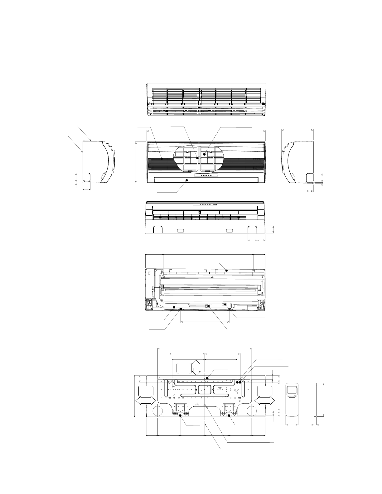
3. CONSTRUCTIONVIEWS
3-1. Indoor Unit
Connecting pipe (0.33m)
(For 10,13 series ; Flare ∅9.52
For 16 series ; Flare ∅12.7)
Knock out system
Back body
Front panel
Air outlet
Air inlet
Air filter
Heat exchanger
Knock out system
660
275
790
208
48
48
26
4519040
32
64
590
320
620
235 235
215 215
9090
275
45
150150 160160
120 80
53
660
Hanger
Hanger
Hanger
Hanger
Hanger
Drain hose (0.54m)
Connecting pipe (0.43m)
(Flare ∅6.35)
For stud bolt
(∅8~∅10)
For stud bolt (∅6)
Installation plate outline
Center line
Minimum
distance
to ceiling
170 or more
Minimum
distance
to ceiling
170 or more
65 or more
Minimum
distance
to ceiling
Wireless remote control
57 18
160
RAS-M10UKCV-E, RAS-M13UKCV-E, RAS-M16UKCV-E
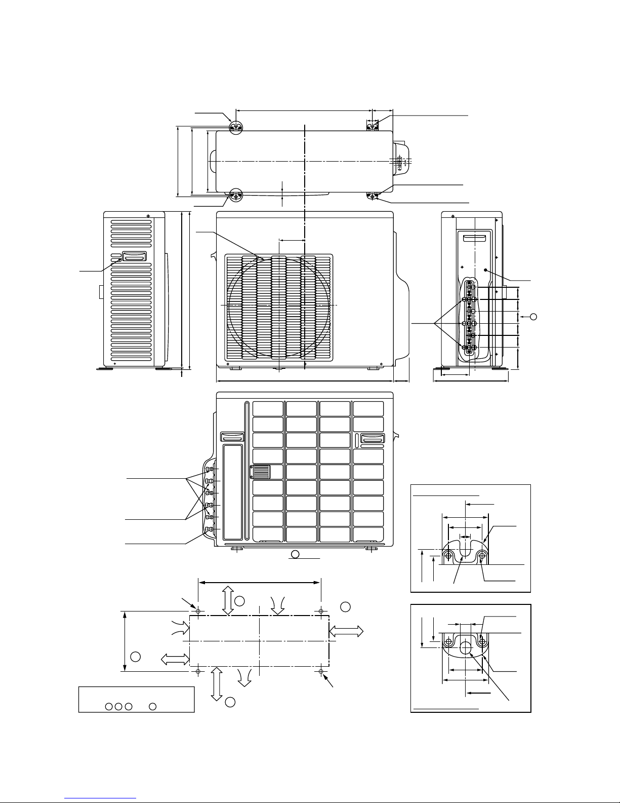
– 16 –
3-2. Outdoor Unit
RAS-3M23YACV-E
115,5
780
68,5
Fan
guard
(For ø8-ø10 anchor bolt)
ø11 × 17U-shape hole
8-ø6 hole
(For fixing outdoor unit)
ø11 × 17 long hole
(For ø8-ø10 anchor bolt)
90
50
600
310
296
270
18
B leg part
(ø6 hole pitch)
(Anchor bolt long hole pitch)
A leg part
2-ø6 hole
2-ø6 hole
600
50
11
R15
36
310
296
600
50
11
R15
36
310
296
R5,5
R5,5
Detailed A leg part
Detailed B leg part
Outside line
of product
Outside line
of product
600
310
B
C
A
D
4 × ø11 × 17U-shape hole
(For ø8-ø10 anchor bolt)
Mounting dimensions of anchor bolt
50 or more
Intake
Intake
100 or
more
250 or more
200 or more
(Minimum distance
from wall)
Outside line
of product
Outlet
4 × ø11 × 17 long hole
(For ø8-ø10 anchor bolt)
8
687
695
Hanger
123,8
332
86,2
53 53 53
53 53
Z
Charging
port
Valve
cover
For installation of the outdoor unit,
open (60cm or more) two directions at
least of A , B , C , and D directions.
Connecting pipe port
(Pipe dia.ø6,35)
Connecting pipe port
(Pipe dia.ø9,52)
Connecting pipe port
(Pipe dia.ø12,7)
view
Z
– 17 –
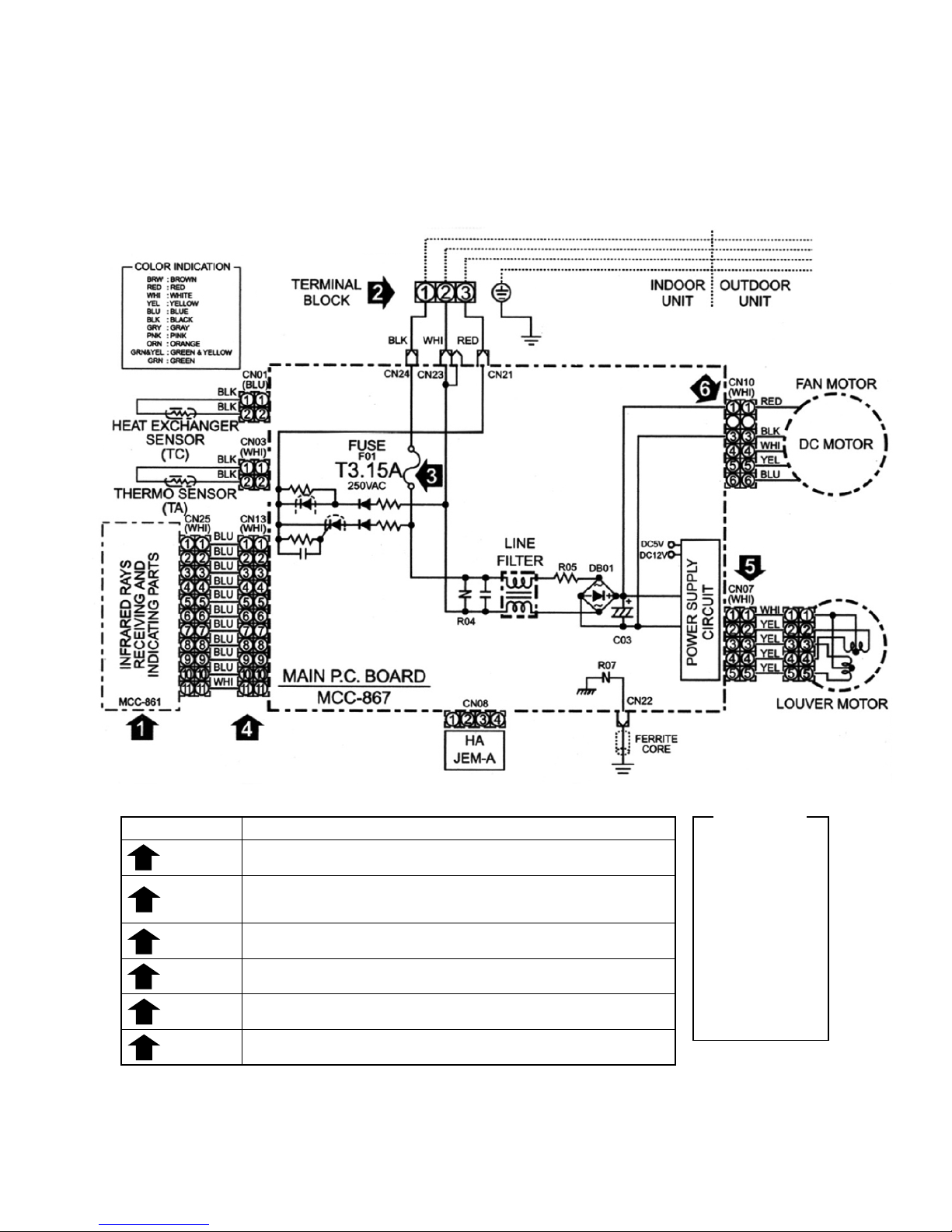
4. WIRING DIAGRAM
4-1. Indoor Unit
RAS-M10UKCV-E
RAS-M13UKCV-E
RAS-M16UKCV-E
Table 4-1-1 Simple check points for diagnosing faults
Diagnosis result
Check to see if the OPERATION indicator goes on and off when the main switch
or breaker is turned on.(Check the primary and secondary voltage of transformer.)
Check for power supply voltage between
and
.(Refer to the name plate.)
(Check the primary and secondary voltage of transformer.)
Check for fluctuate voltage between
–
. (DC 15 ~ 60V)
Check to see if the fuse blows out.
(Checkthe R04 of the varistor.)
Check the voltage at the No.4 pin on CN13 connector of the infrared receiver.
(Check the transformer and the power supply circuit of the rated voltage.)
Check for voltage at the while lead of louver motor.
(Check the transformer and the power supply circuit of the rated voltage.)
Check the voltage at the No.1 pin on CN10 connector.
(Check the DB01, R05 and C03.)
Refer to the service data for the detailed failure diagnosis.
Check items
OPERATION
INDICATOR
TERMINAL
BLOCK
FUSE
6.3A
DC 5V
DC 12V
DC 35V
1
2
3
4
5
6
Color
Identification
BRW : BROWN
RED : RED
WHI : WHITE
YEL : YELLOW
BLU : BLUE
BLK : BLACK
GRY : GRAY
PNK : PINK
ORN : ORANGE
GRN : GREEN &
&YEL YELLOW
(DC310 ~ 340V)
GRN : GREEN
– 18 –
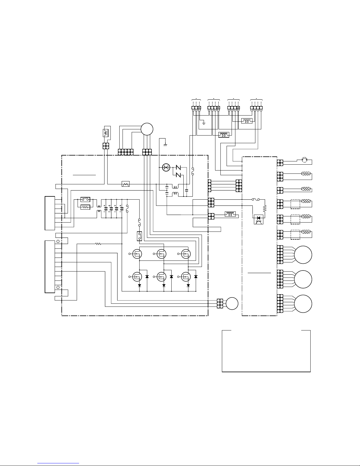
4-2. Outdoor Unit
RAS-3M23YACV-E
REACTOR
11
22
COLOR IDENTIFICATION
BLK : BLACK
BLU : BLUE
ORN : ORANGE
GRY : GRAY
PNK : PINK
WHI : WHITE
BRW : BROWN
RED : RED
YEL : YELLOW
PUR : PURPLE
GRN : GREEN
SKB : SKY-BLUE
CN08
P.M.V.
A UNIT
POWER
SUPPLY
220–230–240V~
50Hz
SURGE
ABSORBER
CN300
FAN MOTOR
P.C. BOARD
MCC-758
REACTOR
CN301
CT
CONVERTER
MODULE
IGBT MODULE
ELECTRONIC
STARTER
POWER RELAY
G
E
A
~
–
~
+
+
BU
EU
BV
EV
BW
EW
BX
BY
BZ
–
C15C13
C14C12
P07P08
ORN P10
YEL
DB01
P20
BLU
Q200
P18
P17
P19
P09
P06
F01
FUSE
25A
VARISTOR
To
INDOOR
UNIT
A
To
INDOOR
UNIT
B
TD
WHI
YEL
ORN
BLU
RED
GRY
P.M.V.
B UNIT
WHI
YEL
ORN
BLU
RED
GRY
ORN
PNK
WHI
CN501
P12
P13
P11
P14
YEL
YEL
PUR
CN704
BLKBLK
PNK
YEL
RED
WHI
BLK
GRY
P04
RED
P05
WHI
BRW
RED
ORN
YEL
BLK
BRW
RED
ORN
YEL
P06
CN15
P02
GRY
ORN
BLK
BLK
BLK
BLK
BLK
P01
L
321
321
123
1234455
221
1
N 1 2 3 1 2 3
~ ~ ~ ~~~ ~ ~ ~ ~ ~
P03
1 1
2 2
CN02
CN03
CN05
CN14
CN13
1 1
2 2
3 3
1 1
2 2
1 1
2 2
3 3
6 6
5 5
4 4
3 3
2 2
1 1
6 6
5 5
4 4
3 3
2 2
1 1
P.M.V. : PULSE MODULATING VALVE
P.M.V.
C UNIT
WHI
YEL
ORN
BLU
RED
GRY
CN12
6 6
5 5
4 4
3 3
2 2
1 1
THERMOSTAT for COMPRESSOR
PHOTO
COUPLER
F03
FUSE
15A
F04
FUSE
3,15A
F01
FUSE 6,3A
313
1
4
3
2
1
4
3
2
1
4
3
2
1
TO
YEL
TGa
CN06
1 1
2 2
3 3
BRW
TGb
CN07
1 1
2 2
3 3
GRN
TGc
RELAY
BLKP23
WHIP22
REDP21
FM
To
INDOOR
UNIT
C
1 2 3 4
~ ~ ~ ~
SUB
P.C. BOARD
MCC-775
3
2
1
3
2
1
COMPRESSOR
CM
REACTOR
REACTOR

– 19 –
5. SPECIFICATIONS OF ELECTRICAL PARTS
5-1. Indoor Unit
RAS-M10YKCV-E, RAS-M13YKCV-E, RAS-M16YKCV-E
No. Parts name Type Specifications
1 Fan motor (for indoor) ICF-340-30-2 DC340V, 30W
2 Ther mo. sensor (TA-sensor) ( – ) 10kΩ at 25°C
3 DC-DC transformer (T01) SWT-70 DC390V, Secondar y DC15V, 12V, 7V
4 Microcomputer ( – )
5
Heat exchanger sensor
( – ) 10kΩ at 25°C
(TC-sensor)
6 Line filter (L01) SS11V-06270 27mH, AC0,64A
7 Diode (DB01) D3SBA60 4A, 600V
8 Capacitor (C03) KMH450VNSN120M25C 120µF, 450V
9 Fuse (F01) FCU250V3.15A T3,15A, 250V
10 Power supply IC (IC01) STR-L472
11 Varistor (R21, R109) 15G561K 560V
12 Resistor (R01) RF-5TK5R6 4,7Ω,5W
13 Louver motor MP24GA Output (Rated) 1W, 1 6poles, 1phase DC12V
5-2. Outdoor Unit
RAS-3M23YACV-E
No. Parts name Model name Rating
1 SC coil (Noise filter)
SC-15-S06J 15A, 0,6mH
SC-20-01J 20A, 150µH
Primary side DC280V
2 DC-DC transformer SWT-43 Secondary side 7,5V x 1, 13V x 1
26,5V x 3, 16V x 1, 15V x 1
3 Reactor CH38Z-K L=10mH, 16A x 2
4 Outside fan motor ICF-140-40-8 DC140V, 40W
5 Fan control relay AJQ1341
Coil DC12V
Contact AC125V, 3A
6
Discharge temp. sensor
(Inverter attached) 62kΩ (20°C)
(TD sensor)
7
Outside air temp. sensor
(Inverter attached) 10kΩ (25°C)
(TO sensor)
8
Temp. sensor at A room
(Inverter attached) 10kΩ (25°C)
gas side (TGa sensor)
9
Temp. sensor at B room
(Inverter attached) 10kΩ (25°C)
gas side (TGb sensor)
10
Temp. sensor at C room
(Inverter attached) 10kΩ (25°C)
gas side (TGc sensor)
11 Terminal block (9P) ——— 20A, AC250V (9P x 2)
For protection of
3,15A, AC250V
switching power source
12 Fuse
For protection of transistor
15A, AC250V
module breakage
For protection of
25A, AC250V
inverter input overcurrent
13 Electrolytic capacitor
LLQ2G501KHUATF
500µF, DC400V X 4 pieces
400LISN500K35F
14 Transistor module 6MBI25GS-060-01 25A, 600V
15 Compressor DA130A1F-21F 3-phases 4-poles 1100W
16 Compressor thermo. PW-2AL OFF: 125 ± 4°C, ON: 90 ± 5°C
17 Converter module MP7002 Diode: 25A, 600V, IGBT: 40A, 600V
18 Reactor CH43Z-K L = 10mH, 1A x 2
– 20 –
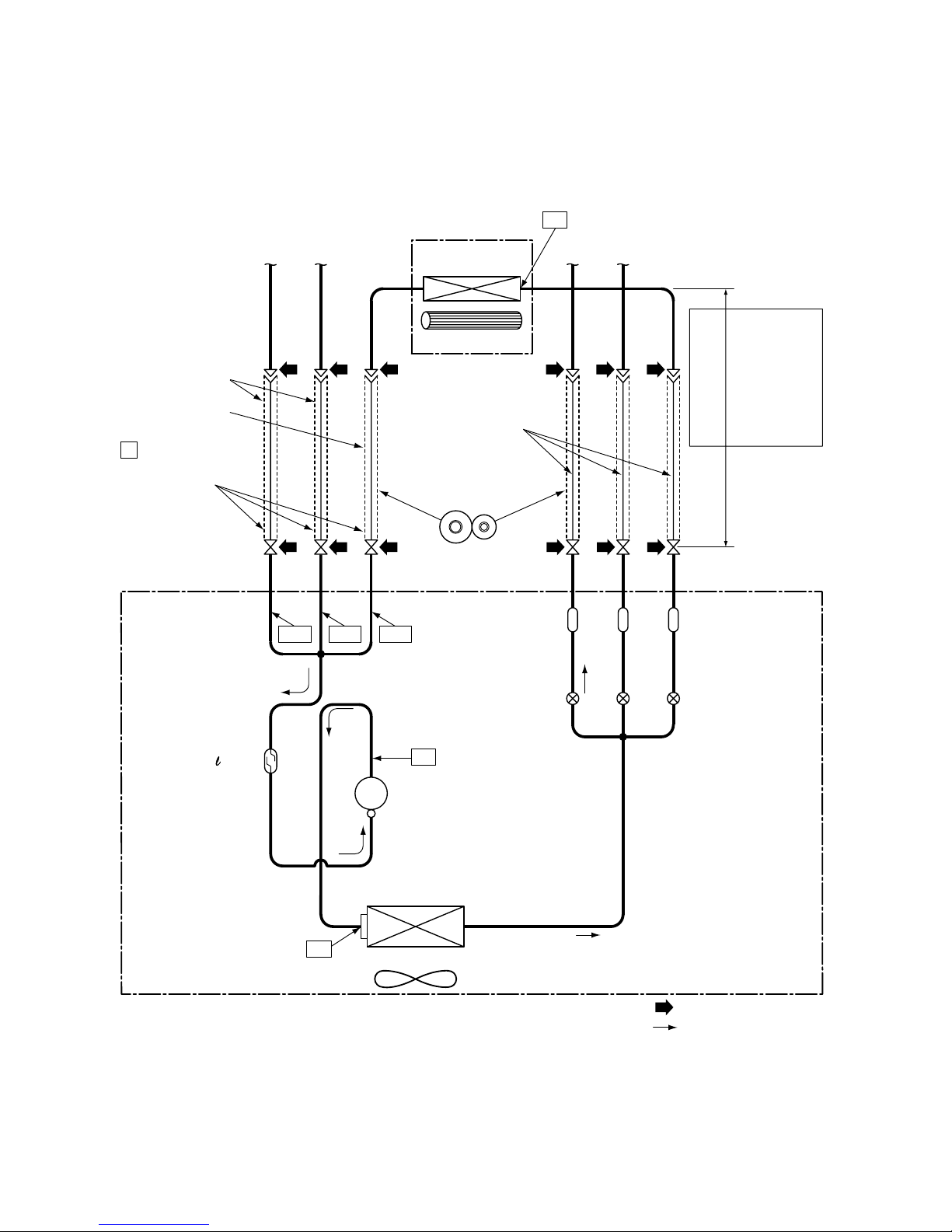
6. REFRIGERANT CYCLE DIAGRAM
6-1. Refrigerant Cycle Diagram
NOTE :
The maximum pipe length of this air conditioner is 40 m. The additional charging of refrigerant is unnecessary
because this air conditioner is designed with charge-less specification.
Connecting pipe
Thickness : 0,8 mm
Ø9,52 :
RAS-M10UKCV-E
RAS-M13UKCV-E
Ø12,7 :
RAS-M16UKCV-E
NOTE :
Gas leak check position
Refrigerant flow
INDOOR UNIT A
T1
Temp. measurement
To
C room
To
B room
Indoor heat
exchanger
Cross flow fan
Sectional shape
of heat insulator
To
C room
To
B room
Allowable height
difference : 10m
Allowable pipe length
Per 1 unit
Max. : 20m
Min. : 2m
Total
Max. : 40m
P
Strainer
Pulse modulating
valve at liquid side
(SEV15RC2)
TGa
TGb
TGc
TD
Accumulating tank
Ø51 x 300
(460cc)
Compressor
DA130A1F-21F
T
2
Outdoor heat
exchanger
Temp. measurement
Propeller fan
Refrigerant amount : 1,5kg (R410A)
OUTDOOR UNIT
Connecting pipe
Thickness : 0,8 mm
Ø6,35
Pressure
measurement
Gauge attaching port
Vacuum pump
connecting port
(Ø9,52) (Ø9,52) (Ø12,7) (Ø6,35) (Ø6,35) (Ø6,35)
– 21 –
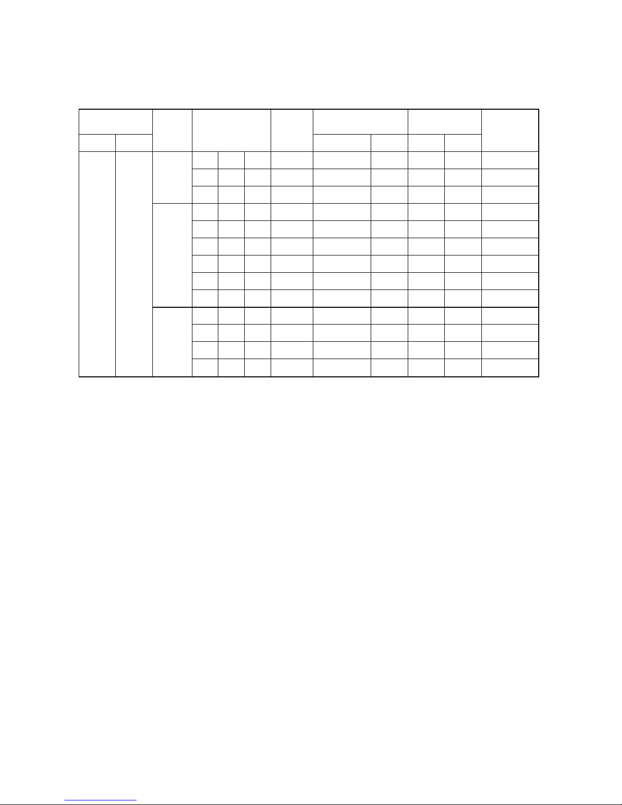
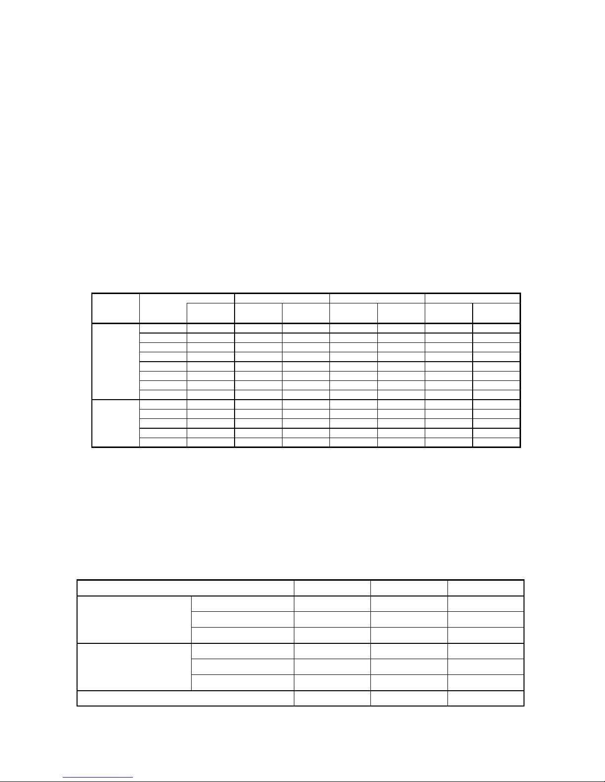
6-2. Operation Data
NOTE :
Model of Indoor unit 10 : RAS-M10UKCV-E, 13 : RAS-M13UKCV-E, 16 : RAS-M16UKCV-E
NOTES :
(1) Measure surface temperature of heat exchanger pipe around center of heat exchanger path U bent.
(Thermistor themometer)
(2) Connecting piping condition : 5 meters x 3 units (5m / each unit)
Temperature
No. of
condition (°C)
operating
Indoor Outdoor
units
1 unit
2 units
27/19 35/–
3 units
Combinations
of indoor units
10 — —
13 — —
16 — —
10 10 —
13 10 —
16 10 —
13 13 —
16 13 —
16 16 —
10 10 10
13 10 10
16 10 10
13 13 10
Standard
Surface temp. of
pressure
heat exchanger
P (Mpa)
T1 (°C) T2 (°C)
0,92 11 42
0,85 9 47
0,73 8 50
0,96 10,5 to 11,5 4 9
0,92 11 to 12 51
0,92 11 to 12 51
0,92 11 to 12 51
0,92 11 to 12 51
0,92 11 to 12 51
1,04 12,5 to 13,5 5 1
0,98 12 to 13 52
0,98 12 to 13 52
0,98 12 to 13 52
Fan speed
Compressor
revolution
Indoor Outdoor
(rps)
High Med. 37
High High 57
High High 73
High High 69
High High 78
High High 78
High High 78
High High 78
High High 78
High High 81
High High 89
High High 89
High High 89
– 22 –
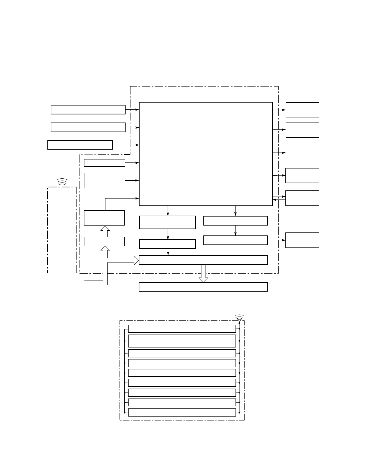
7. CONTROL BLOCK DIAGRAM
7-1. Indoor Unit
Remote Control
Operation (START/STOP)
Operation Mode Selection
AUTO, COOL, DRY, FAN ONLY
Temperature Setting
Fan Speed Selection
ON TIMER Setting
OFF TIMER Setting
Louver Auto Swing
Louver Direction Setting
ECONO.
Infrared
Rays
REMOTE CONTROL
Indoor Unit Control Panel
Heat Exchanger Sensor
Temperature Sensor
Infrared Rays Signal Receiver
Initiallizing Circuit
Clock Frequency
Oscillator Circuit
Power Supply
Circuit
Noise Filter
From Outdoor Unit
M.C.U.
Functions
• Louver Control
• 3-minute Delay at Restart for Compressor
• Motor Revolution Control
• Processing
(Temperature Processing)
• Timer
Louver ON/OFF Signal
Louver Driver
Relay RY04
Outdoor Unit
Operation
Display
Timer
Display
Filter Sign
Display
Indoor Fan
Motor
Fan Only
Sign Display
Louver Motor
Infrared
Rays
Remote
Control
Outdoor unit
ON/OFF Signal
Relay Driver
RAS-M10UKCV-E, RAS-M13UKCV-E, RAS-M16UKCV-E

– 23 –
7-2. Outdoor Unit (Inverter Assembly)
MCC-775 (SUB P.C.B) MCC-758 (MAIN P.C.B)
220–230–240V ~ 50Hz
For Indoor unit
Outdoor air
temp. sensor
Discharge
temp. sensor
Gas side
A, B, C pipe
temp. sensor
C unit
send/receive
circuit
A unit
send/receive
circuit
B unit
send/receive
circuit
Compressor
Outdoor
fan motor
• PWM synthesis function
• Input current release control
• IGBT over-current detect control
• Outdoor fan control
• High power factor correction control
• Signal communication to MCU
M.C.U
Input current
Sensor
Over current
sensor
Over current
sensor
Converter
(AC
DC)
Inverter
(DC
AC)
Inverter
(DC
AC)
Noise
filter
High power factor
correction circuit
Over current
detect circuit
Over current
detect circuit
Rotor position
detect circuit
Rotor position
detect circuit
Gate drive
circuit
Gate drive
circuit
• Inverter output frequency control
• A/D converter function
• P.M.V. control
• Discharge temp. control
• Error display
• Signal communication to MCU
M.C.U
Driver circuit of P.M.V.
C unit
P.M.V.
P.M.V. : Pulse Modulating Valve
PWM : Pulse Width Modulation
IGBT : Insulated Gate Bipolar Transistor
A unit
P.M.V.
B unit
P.M.V.

– 24 –
8. OPERATION DESCRIPTION
8-1. Outline of Air Conditioner Control
This air conditioner is a capacity-variable type air
conditioner, which uses DC motor f or the indoor fan
motors and the outdoor fan motor . And the capacityproportional control compressor which can change
the motor speed in the range from 13 to 120 rps is
mounted. The DC motor drive circuit is mounted to
the indoor unit. The compressor and the inverter to
control fan motor are mounted to the outdoor unit.
The entire air conditioner is mainly controlled by the
indoor unit controller.
The indoor unit controller drives the indoor fan motor
based upon command sent from the remote control,
and transfers the operation command to the outdoor
unit controller.
The outdoor unit controller receives operation
command from the indoor unit side, and controls the
outdoor fan and the pulse modulating valv e.
Besides, detecting revolution position of the compressor motor, the outdoor unit controller controls
speed of the compressor motor by controlling output
voltage of the inv erter and switching timing of the
supply power (current transfer timing) so that motors
drive according to the operation command. And
then, the outdoor unit controller transfers re v ersely
the operating status information of the outdoor unit
to control the indoor unit controller.
As the compressor adopts four-pole brushless
DC motor, the frequenc y of the supply power
from inverter to compressor is two-times
cycles of the actual number of rev olution.
(1) Role of indoor unit controller
The indoor unit controller judges the operation
commands from the remote control and assumes the following functions.
• Judgment of suction air temperature of the
indoor heat exchanger by using the indoor
temp. sensor .
• Temperature setting of the indoor heat exchanger by using heat exchanger sensor
(Prevent-freezing control)
• Louver motor control
• Indoor fan motor operation control
• LED display control
• Transferring of operation command signal
(Serial signal) to the outdoor unit
• Reception of information of operation status
(Serial signal including outside temp. data) to
the outdoor unit and judgment/display of error
(2) Role of outdoor unit controller
Receiving the operation command signal (Serial
signal) from the indoor controller, the outdoor
unit performs its role.
• Compressor operation
control
• Operation control of
outdoor fan motor
• P.M.V . control
Operations followed
to judgment of serial
signal from indoor
side.
• Detection of inverter input current and current
release operation
• Over-current detection and prev ention operation to transistor module (Compressor stop
function)
• Compressor and outdoor fan stop function
when serial signal is off (when the serial signal
does not reach the board assembly of outdoor
control by trouble of the signal system)
• Transferring of operation information (Serial
signal) from outdoor unit to indoor unit
• Detection of outdoor temperature and operation revolution control
(3) Contents of operation command signal (Serial
signal) from indoor unit controller to outdoor unit
controller
The following three types of signals are sent
from the indoor unit controller.
• Operation mode set on the remote control
• Compressor revolution command signal defined
by indoor temperature and set temperature
(Correction along with variation of room
temperature and correction of indoor heat
exchanger temperature are added.)
• For these two types of signals ( [Operation
mode] and [Compressor revolution] ), the
outdoor unit controller monitors the input
current to the inverter, and perf orms the
followed operation within the range that
current does not exceed the allowab le v alue.
• T emperature of indoor heat e xchanger b y indoor
heat exchanger sensor
(Minimum revolution control)

– 25 –
(4) Contents of operation command signal (Serial
signal) from outdoor unit controller to indoor unit
controller
The following signals are sent from the outdoor
unit controller.
• The current operation mode
• The current compressor revolution
• Outdoor temperature
• Existence of protective circuit operation
For transferring of these signals, the indoor
unit controller monitors the contents of signals,
and judges existence of trouble occurrence .
Contents of judgment are described below.
• Whether distinction of the current operation
status meets to the operation command
signal
• Whether protective circuit operates
When no signal is received from the
outdoor unit controller, it is assumed as a
trouble.
8-1-1. Capacity Control
The cooling capacity is varied by changing compressor motor speed. The inverter changes compressor
motor speed by changing AC 220–230–240V power
to DC once, and controls capacity by changing
supply power status to the compressor with transistor module (includes 6 transistors). The outline of the
control is as follows: The revolution position and
revolution speed of the motor are detected by
detecting winding electromotive force of the compressor motor under operation, and the revolution
speed is changed so that the motor drives based
upon revolution speed of the operation command b y
changing timing (current transfer timing) to exchange inverter output voltage and supply power
winding.
Detection of the revolution position for controlling is
performed 12 times per 1 revolution of compressor.
The range of supply power frequency to the compressor differs according to the operation status
(COOL, DRY).
T able 8-1-1 Compressor re volution range
No. of Combination of Compressor
operating unit indoor units revolution (rps)
RAS-M16UKCV-E 16 to 77
1 unit RAS-M13YKCV-E 16 to 72
RAS-M10YKCV-E 16 to 45
2 units
¡
*
19 to 84
3 units
¡
*
23 to 92
*
: In case that any multiple indoor units are combined.
8-1-2. Current Release Control
The outdoor main circuit control section (Inverter
assembly) detects the input current to the outdoor
unit. If the current v alue with compressor motor
speed instructed from indoor side exceeds the
specified value, the outdoor main circuit control
section controls compressor motor speed by reducing motor speed so that value becomes closest to
the command within the limited value.
8-1-3. Power Factor Improvement Control
Pow er factor improvement control is performed
mainly aiming to reduce the current on much power
consumption of cooling operation. Controlling starts
from the time when input power has reached at a
certain point. To be concrete, IGBT of the power
factor improv ement circuit is used, and the po wer
factor is improv ed by keeping IGBT on for an arbitrary period to widen electro-angle of the input
current.
8-1-4. Prevent-Freezing Control
The indoor heat exchanger sensor detects refrigerant vapor temperature in COOL/DR Y operation. If
the temperature is below the specified value, compressor motor speed is reduced so that operation is
performed in temperature below the specified value
to prevent-freezing of indoor heat e xchanger.
8-1-5. P. M. V. (Pulse Modulating Valve)
Using P.M.V., refrigerant flow of refrigeration cycle is
varied for the optimum temperature . Controlling
each unit separately by three P.M.V. corresponds to
difference of pipe length, fan speed, and unit temperature.
If an error occurs on cycle temperature when power
source of the air conditioner has been turned on,
and if start/stop times of the outdoor unit are 30
times, move the valve once until it hits on the
stopper for positioning of the valv e . In this case,
ticktack sound may be heard.
– 26 –
8-1-6. Louver Control
(1) Vertical air flow louvers
Positions of vertical air flow louv ers are automatically controlled according to the operation
status (COOL, AUTO, DRY, FAN ONLY). Besides, positions of vertical air flow louvers can be
arbitrarily set by pressing the [SET] button. The
louver position which has been set by the [SET]
button is stored in microcomputer , and the louv er
is automatically set at the stored position in the
next operation.
(2) Swing
If the [AUT O] b utton is pressed during running
operation, vertical air flow louvers start swinging.
When the [AUT O] button is pressed again,
swinging stops.
8-1-7. Indoor Fan Control (DC Fan Motor)
The indoor fan is operated by motor speed non-step
variable DC drive system motor. For flow rate, motor
speed is controlled manually in three steps (LOW,
MED , HIGH), and with the unit of 10 rpm from upper
limit to lower limit in AUTO mode as described in
Table 8-1-3. It is not selected by relay, so selecting
sound does not generate.
T able 8-1-3
NOTE : UL : Ultra Low, SUL : Super Ultra Low
8-1-8. Outdoor Fan Control (DC Fan Motor)
Although the outdoor fan motor drives the outdoor f an b y non-step v ariable system of the revolution speed, the
revolution speed is restricted to three steps on the conv enience of controlling.
If a strong wind is lashing outside of the room, the operation may be continued as the outdoor f an stops in order
to protect the outdoor fan motor.
If a fan lock occurred due to entering of foreign matter, the air conditioner stops and an alarm is displayed.
T able 8-1-4
Compressor revolution (rps)
~
17,4
~
38,9 39
~
Outdoor temp. sensor
TO ≥ 38°C 500 (rpm) 800 (rpm) 800 (rpm)
TO
38°C > TO ≥ 15°C 500 (rpm) 700 (rpm) 800 (rpm)
15°C > TO 390 (rpm) 390 (rpm) 390 (rpm)
TO ≥ 38°C 500 (rpm) 700 (rpm) 800 (rpm)
ECONO. operation 38°C > TO ≥ 15°C 500 (rpm) 500 (rpm) 700 (rpm)
15°C > TO 390 (rpm) 390 (rpm) 390 (rpm)
TO is abnormal 700 (rpm) 700 (r pm) 800 (rpm)
Remote
Motor speed
ir flow rate Motor speed
ir flow rate Motor speed Air flow rate
mode mode Control
( rpm )
( m
/h )
( rpm )
( m
/h )
( rpm )
( m
/h )
H HIGH 1190 560 1210 590 1350 670
M 1080 510 1130 530 1250 610
MED 1100 510 1130 530 1250 610
M MED 1000 460 1050 490 1150 550
LOW 960 440 990 460 1070 500
L 950 430 950 430 1050 490
L LOW 910 400 910 400 980 450
L 850 370 850 370 920 410
L 950 430 950 430 1050 490
L 910 400 910 400 980 450
L 850 370 850 370 920 410
UL 720 300 750 310 920 410
SUL 660 260 700 280 800 340
RAS-M13UKCV-E RAS-M16UKCV-E
DRY
Cooling
and Fan
only
RAS-M10UKCV-E
FanOperation
+
-
+
-
+
+
+
 Loading...