

Toshiba RAS-18N3AV2, RAS-B18N3KV2, RAS-4M27UAV-E, RAS-5M34UAV-E1, RAS-22N3AV2 Installation Manual
...
AIR CONDITIONER (SPLIT TYPE)
INSTALLATION MANUAL
1110651195
Indoor unit
RAS-(B)18, 22N3KV2 Series
RAS-M24N3KV2 Series
Outdoor unit
RAS-18, 22N3AV2 Series
RAS-3M26UAV-E
RAS-4M27UAV-E
RAS-5M34UAV-E1
ENGLISH
DEUTSCH
ČESKY
PУCСКИЙ
MAGYAR
ΕΛΛΗΝΙΚΑ
БЪЛГАРСКИ
SLOVENČINA
SLOVENŠČINA

PRECAUTIONS FOR SAFETY ...........................................................................................................................................1
INSTALLATION DIAGRAM OF INDOOR AND OUTDOOR UNITS ...................................................................................3
Optional Installation Parts ...............................................................................................................................................3
INDOOR UNIT .....................................................................................................................................................................4
Installation Place .............................................................................................................................................................4
Cutting a Hole and Mounting Installation Plate ...............................................................................................................4
Wiring Connection ...........................................................................................................................................................4
How to Connect Remote Controller for Wire Operation ..................................................................................................5
Piping and Drain Hose Installation ..................................................................................................................................6
Indoor Unit Fixing ............................................................................................................................................................7
Drainage .........................................................................................................................................................................7
OUTDOOR UNIT .................................................................................................................................................................7
Installation Place .............................................................................................................................................................7
Precautions about Installation in Regions with Snowfall and Cold Temperatures ..........................................................7
Refrigerant Piping Connection ........................................................................................................................................8
Evacuating .....................................................................................................................................................................8
Wiring Connection ...........................................................................................................................................................8
Electrical Work ................................................................................................................................................................9
OTHERS ..............................................................................................................................................................................9
Gas Leak Test .................................................................................................................................................................9
Remote Control A-B Selection ........................................................................................................................................9
Test Operation ................................................................................................................................................................9
Auto Restart Setting .......................................................................................................................................................9
CONTENTS
EN
EN
ES
FR
IT
DE
PT
PL
CZ
RU
CR
HU
TR
NL
GR
SV
FI
NO
DK
RO
BG
EE
LV
SK
SI
1
EN
PRECAUTIONS FOR SAFETY
PRECAUTIONS FOR SAFETY
New refrigerant air conditioner installation
CAUTION
• THIS AIR CONDITIONER USES THE NEW HFC REFRIGERANT (R410A), WHICH DOES NOT DESTROY THE OZONE LAYER.
R410A refrigerant is apt to be affected by impurities such as water, oxidizing membranes, and oils because the pressure of R410A refrigerant is approx.
1.6 times of refrigerant R22. As well as the adoption of this new refrigerant, refrigerating machine oil has also been changed. Therefore, during installation
work, be sure that water, dust, former refrigerant, or refrigerating machine oil does not enter the refrigeration cycle of a new-refrigerant air conditioner.
To avoid mixing refrigerant and refrigerating machine oil, the sizes of charging port connecting sections on the main unit are different from those for the
conventional refrigerant, and different size tools are also required. For connecting pipes, use new and clean piping materials with high pressure withstand
capabilities, designed for R410A only, and ensure that water or dust does not enter. Moreover, do not use any existing piping as its pressure withstand
may be insuffi cient and may contain impurities.
DANGER
• FOR USE BY QUALIFIED PERSONS ONLY.
• TURN OFF MAIN POWER SUPPLY BEFORE ATTEMPTING ANY ELECTRICAL WORK. MAKE SURE ALL POWER SWITCHES ARE OFF.
FAILURE TO DO SO MAY CAUSE ELECTRIC SHOCK.
• CONNECT THE CONNECTING CABLE CORRECTLY. IF THE CONNECTING CABLE IS CONNECTED WRONGLY, ELECTRIC PARTS MAY BE
DAMAGED.
• CHECK THE EARTH WIRE THAT IT IS NOT BROKEN OR DISCONNECTED BEFORE INSTALLATION.
• DO NOT INSTALL NEAR CONCENTRATIONS OF COMBUSTIBLE GAS OR GAS VAPORS.
FAILURE TO FOLLOW THIS INSTRUCTION CAN RESULT IN FIRE OR EXPLOSION.
• TO PREVENT OVERHEATING THE INDOOR UNIT AND CAUSING A FIRE HAZARD, PLACE THE UNIT WELL AWAY (MORE THAN 2 M) FROM HEAT
SOURCES SUCH AS RADIATORS, HEATERS, FURNACE, STOVES, ETC.
• WHEN MOVING THE AIR CONDITIONER FOR INSTALLING IT IN ANOTHER PLACE AGAIN, BE VERY CAREFUL NOT TO GET THE SPECIFIED
REFRIGERANT (R410A) WITH ANY OTHER GASEOUS BODY INTO THE REFRIGERATION CYCLE. IF AIR OR ANY OTHER GAS IS MIXED IN THE
REFRIGERANT, THE GAS PRESSURE IN THE REFRIGERATION CYCLE BECOMES ABNORMALLY HIGH AND IT RESULTINGLY CAUSES BURST
OF THE PIPE AND INJURIES ON PERSONS.
• IN THE EVENT THAT THE REFRIGERANT GAS LEAKS OUT OF THE PIPE DURING THE INSTALLATION WORK, IMMEDIATELY LET FRESH AIR
INTO THE ROOM. IF THE REFRIGERANT GAS IS HEATED BY FIRE OR SOMETHING ELSE, IT CAUSES GENERATION OF POISONOUS GAS.
For general public use
Power supply cord of parts of appliance for outdoor use shall be at least polychloroprene sheathed fl exible cord (design H07RN-F) or cord designation
60245 IEC66 (1.5 mm
2
or more). (Shall be installed in accordance with national wiring regulations.)
• Before installation, please read these precautions for safety carefully.
• Be sure to follow the precautions provided here to avoid safety risks. The symbols and their meanings are shown below.
WARNING : It indicates that incorrect use of this unit may cause severe injury or death.
CAUTION : It indicates that incorrect use of this unit may cause personal injury (*1), or property damage (*2).
*1: Personal injury means a slight accident, burn, or electrical shock which does not require admission or repeated hospital treatment.
*2: Property damage means greater damage which affects assets or resources.
2
WARNING
• Never modify this unit by removing any of the safety guards or bypassing any of the safety interlock switches.
• Installation work must be requested from the supplying retail dealership or professional vendors. Self-installation may cause water leakage, electrical
shock, or fi re as a result of improper installation.
• Specifi ed tools and pipe parts for model R410A are required, and installation work must be done in accordance with the manual. HFC type refrigerant
R410A has 1.6 times more pressure than that of conventional refrigerant (R22). Use the specifi ed pipe parts, and ensure correct installation, otherwise
damage and/or injury may be caused. At the same time, water leakage, electrical shock, and fi re may occur.
• Be sure to install the unit in a place which can suffi ciently bear its weight. If the load bearing of the unit is not enough, or installation of the unit is
improper, the unit may fall and result in injury.
• Electrical work must be performed by a qualifi ed electrical engineer in accordance with the code governing such installation work, internal wiring
regulations, and the manual. A dedicated circuit and the rated voltage must be used. Insuffi cient power supply or improper installation may cause
electrical shock or fi re.
• Use a cabtyre cable to connect wires in the indoor/outdoor units. Midway connection, stranded wire, and single-wire connections are not allowed.
Improper connection or fi xing may cause a fi re.
• Wiring between the indoor unit and outdoor units must be well shaped so that the cover can be fi rmly placed. Improper cover installation may cause
increased heat, fi re, or electrical shock at the terminal area.
• Be sure to use only approved accessories or the specifi ed parts. Failure to do so may cause the unit to fall, water leakage, fi re or electrical shock.
• After the installation work, ensure that there is no leakage of refrigerant gas. If the refrigerant gas leaks out of the pipe into the room and is heated by
fi re or something else from a fan heater, stove or gas range, it causes generation of poisonous gas.
• Make sure the equipment is properly earthed. Do not connect the earth wire to a gas pipe, water pipe, lightning conductor, or telephone earth wire.
Improper earth work may be the cause of electrical shock.
• Do not install the unit where fl ammable gas may leak. If there is any gas leakage or accumulation around the unit, it can cause a fi re.
• Do not select a location for installation where there may be excessive water or humidity, such as a bathroom. Deterioration of insulation may cause
electrical shock or fi re.
• Installation work must be performed following the instructions in this installation manual. Improper installation may cause water leakage, electrical shock
or fi re. Check the following items before operating the unit.
- Be sure that the pipe connection is well placed and there are no leaks.
- Check that the service valve is open. If the service valve is closed, it may cause overpressure and result in compressor damage. At the same time, if
there is a leak in the connection part, it may cause air suction and overpressure, resulting in damage to the unit or injury.
• In a pump-down operation, be sure to stop the compressor unit before removing the refrigerant pipe. If removing the refrigerant pipe while the
compressor is operating with the service valve opened, it may cause air suction and overpressure, resulting in damage to the unit or injury.
• Do not modify the power cable, connect the cable midway, or use a multiple outlet extension cable. Doing so may cause contact failure, insulation
failure, or excess current, resulting in fi re or electrical shock.
• Appliance shall be installed in accordance with national wiring regulation.
If you detect any damage do not install the unit. Contact your supplying dealer immediately.
• Do not use any refrigerant different from the one specifi ed for complement or replacement.
Otherwise, abnormally high pressure may be generated in the refrigeration cycle, which may result in a failure or explosion of the product or an injury to
your body.
REQUIREMENT OF REPORT TO THE LOCAL POWER SUPPLIER
Please make absolutely sure that the installation of this appliance is reported to the local power supplier before installation. If you experience any problems
or if the installation is not accepted by the supplier, the service agency will take adequate countermeasures.
CAUTION
• Exposure of unit to water or other moisture before installation could result in electric shock. Do not store it in a wet basement or expose to rain or water.
• After unpacking the unit, examine it carefully for possible damage.
• Do not install in a place that can increase the vibration of the unit. Do not install in a place that can amplify the noise level of the unit or where noise and
discharged air might disturb neighbors.
• Please read this installation manual carefully before installing the unit. It contains further important instructions for proper installation.
• This appliance must be connected to the main power supply by means of a circuit breaker depending on the place where the unit is installed. Failure to do
so may cause electrical shock.
• Follow the instructions in this installation manual to arrange the drain pipe for proper drainage from the unit. Ensure that drained water is discharged.
Improper drainage can result in water leakage, causing water damage to furniture.
• Tighten the fl are nut with a torque wrench using the prescribed method. Do not apply excess torque. Otherwise, the nut may crack after a long period of
usage and it may cause the leakage of refrigerant.
• Wear gloves (heavy gloves such as cotton gloves) for installation work. Failure to do so may cause personal injury when handling parts with sharp edges.
• Do not touch the air intake section or the aluminum fi ns of the outdoor unit. It may cause injury.
• Do not install the outdoor unit in a place which can be a nest for small animals. Small animals could enter and contact internal electrical parts, causing a
failure or fi re.
• Request the user to keep the place around the unit tidy and clean.
• Make sure to conduct a trial operation after the installation work, and explain how to use and maintain the unit to the customer in accordance with the
manual. Ask the customer to keep the operation manual along with the installation manual.
• The manufacturer shall not assume any liability for the damage caused by not observing the description of this manual.
EN
ES
FR
IT
DE
PT
PL
CZ
RU
CR
HU
TR
NL
GR
SV
FI
NO
DK
RO
BG
EE
LV
SK
SI
3
EN
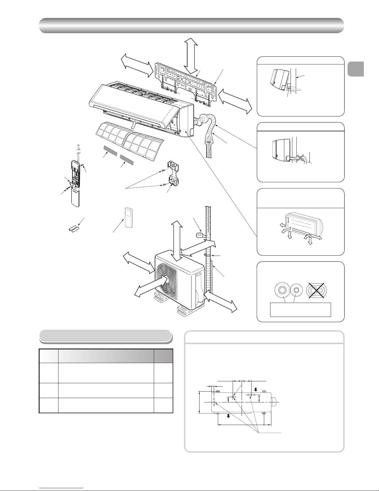
INSTALLATION DIAGRAM OF INDOOR AND OUTDOOR UNITS
INSTALLATION DIAGRAM OF INDOOR AND OUTDOOR UNITS
Part
code
Parts name Q’ty
A
Refrigerant piping
Liquid side : dia. 6.35 mm
Gas side : dia. 12.70 mm
One
each
B
Pipe insulating material
(polyethylene foam, 8 mm thick)
1
C
Putty, PVC tapes
One
each
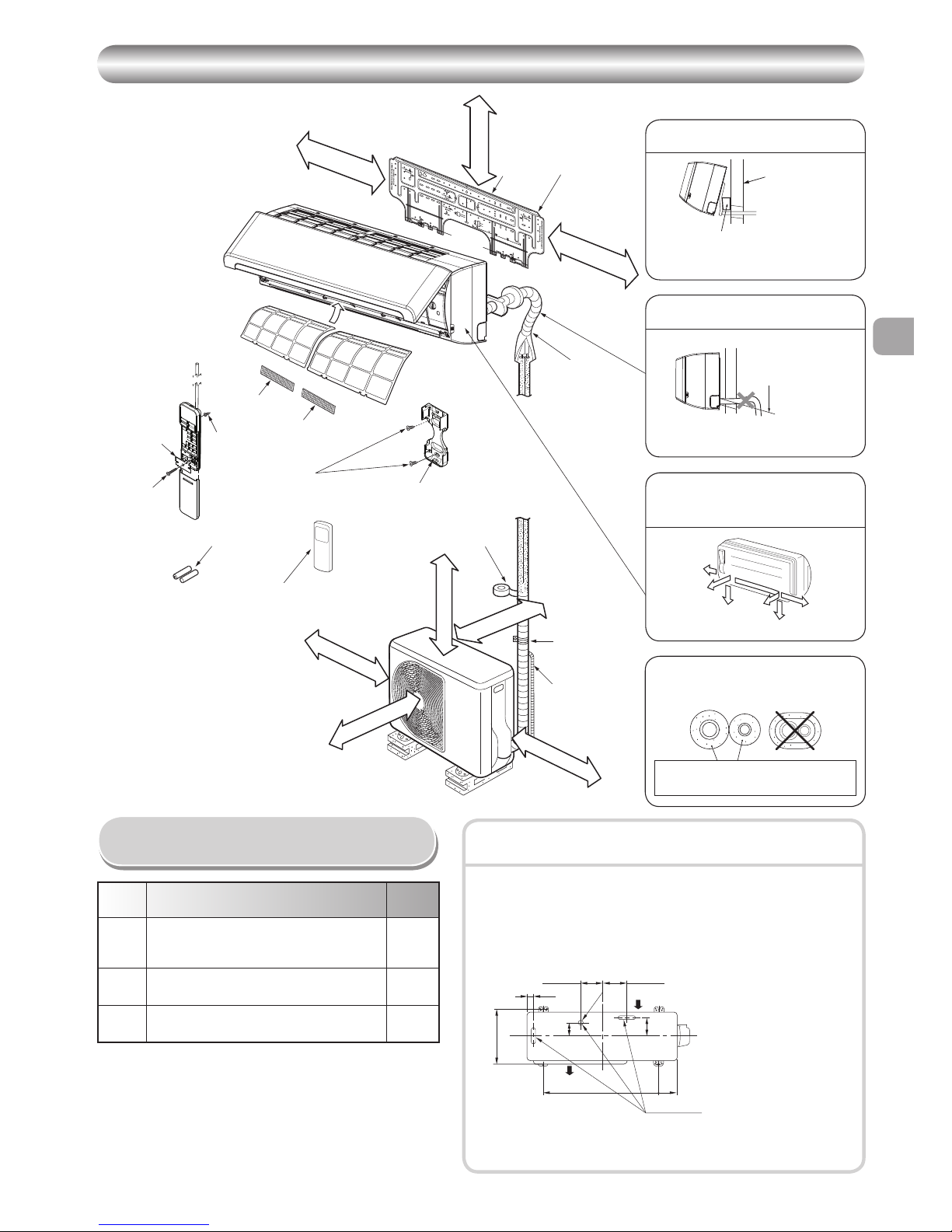
Optional Installation Parts
• Secure the outdoor unit with fi xing bolts and nuts if the unit is likely to be
exposed to a strong wind.
• Use dia. 8 mm or dia. 10 mm anchor bolts and nuts.
• If it is necessary to drain the defrost water, attach drain nipple 9 and cap
water proof ! to the bottom plate of the outdoor unit before installing it.
Fixing bolt arrangement of outdoor unit
Insulate the refrigerant pipes separately
with insulation, not together.
2
3
8
4
Insert the cushion between the indoor
unit and wall, and tilt the indoor unit for
better operation.
For the rear left and left piping
Wall
Make sure to run the drain hose sloped
downward.
Do not allow the drain hose to get slack.
Cut the piping
hole sloped
slightly.
The auxiliary piping can be connected to
the left, rear left, rear right, right, bottom
right or bottom left.
Right
Rear
right
Bottom
right
Rear
left
Bottom left
Left
8 mm thick heat resisting
polyethylene foam
1
Batteries
Flat head
wood screw
Remote control holder
Vinyl tape
Apply after carrying
out a drainage test.
Wireless remote control
Saddle
Extension drain hose
(Not available,
provided by installer)
Shield pipe
(Attach to the front panel.)
Air fi lter
Installation
plate
50 mm or more
170 mm or more
170 mm or more
100 mm or more
100 mm or more
600 mm or more
600 mm or more
Remark :
• Detail of accessory and installation parts can see in the
accessory sheet.
• Some pictures might be different from the actual parts.
5
Filter
Hook
Hook
When installing the outdoor unit, leave open
in at least two of direction (A), (B), (C) and
(D) shown in the fi gure on the right.
(A)
(B)
(C)
(D)
108 mm
28 mm
125 mm
dia. 25 mm
Air inlet
Air outlet
Drain outlet
86 mm
102 mm
320 mm
600 mm
90 mm
600 mm or more
8
Flat head
wood screw
&
(
Flat head
wood screw
Battery cover
The provided Remote Controller is a
wireless type, which also can be used as
a wire.
Please see “How to Connect The Remote
Controller for Wired Operation”, in case of
wired control is required.
w
When using a multi-system outdoor unit is used, refer to the installation
manual provided with the model concerned.
* Drain nipple and cap
water proof are packed
in outdoor unit.
6
Filter
4
INDOOR UNIT
INDOOR UNIT
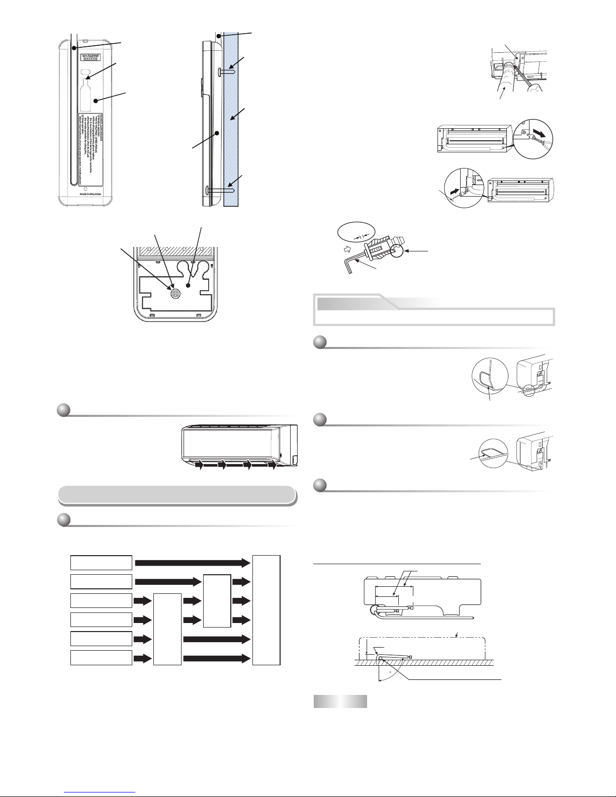
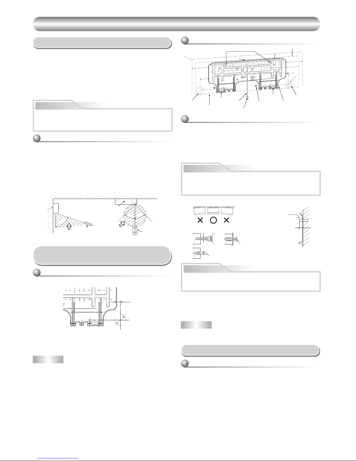
Installation Place
• Direct sunlight to the indoor unit’s wireless receiver should be avoided.
• The microprocessor in the indoor unit should not be too close to RF
noise sources.
(For details, see the owner’s manual.)
Remote control
• A place where there are no obstacles such as a curtain that may block the
signal from the remote control.
• Do not install the remote control in a place exposed to direct sunlight or
close to a heating source such as a stove.
• Keep the remote control at least 1 m apart from the nearest TV set or stereo
equipment. (This is necessary to prevent image disturbances or noise
interference.)
• The location of the remote control should be determined as shown below.
Cutting a Hole and Mounting
Installation Plate
NOTE
• When drilling a wall that contains a metal lath, wire lath or metal plate, be
sure to use a pipe hole brim ring sold separately.
Cutting a hole
When installing the refrigerant pipes from the rear
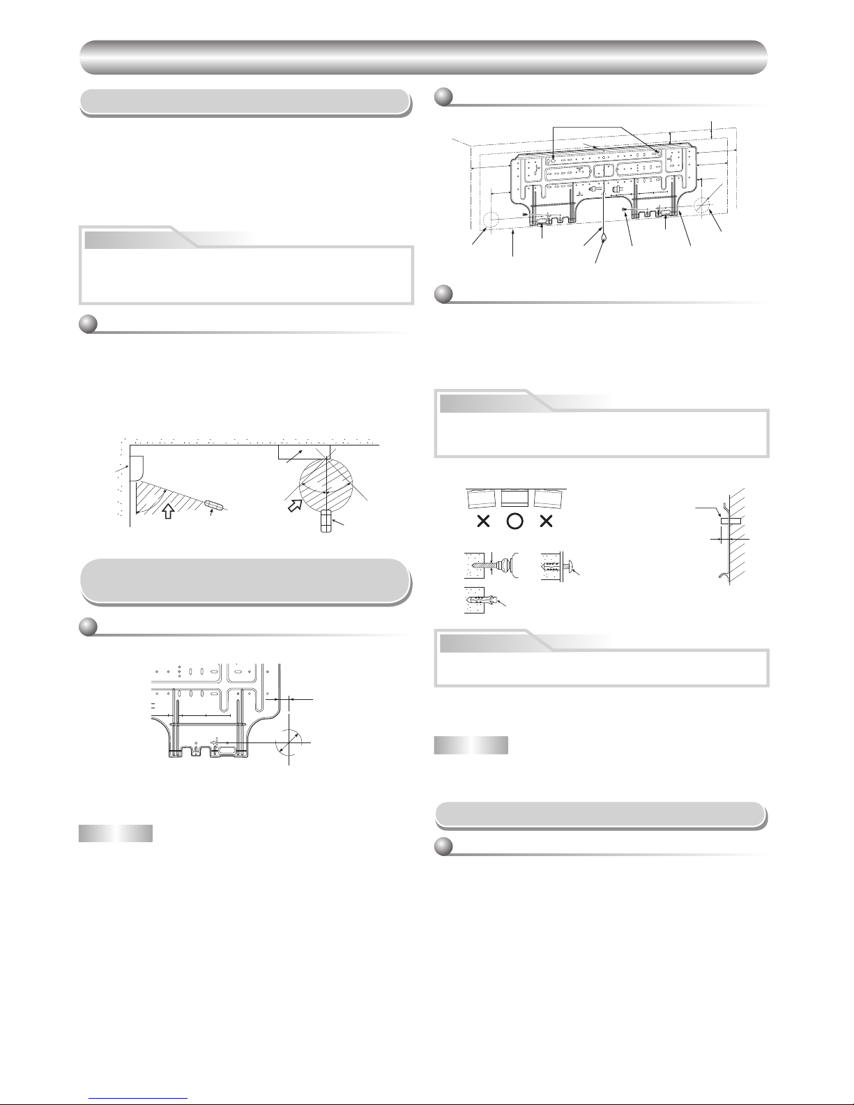
Mounting the installation plate
When the installation plate is directly mounted
on the wall
1. Securely fi t the installation plate onto the wall by screwing it in the upper
and lower parts to hook up the indoor unit.
2. To mount the installation plate on a concrete wall with anchor bolts, use the
anchor bolt holes as illustrated in the below fi gure.
3. Install the installation plate horizontally in the wall.
When installing the installation plate with a mounting screw, do not use
the anchor bolt holes. Otherwise, the unit may fall down and result in
personal injury and property damage.
1. After determining the pipe hole position on the mounting plate (➡), drill the
pipe hole (dia. 65 mm) at a slight downward slant to the outdoor side.
• A place which provides the spaces around the indoor unit as shown in the
diagram
• A place where there are no obstacles near the air inlet and outlet
• A place which allows easy installation of the piping to the outdoor unit
• A place which allows the front panel to be opened
• The indoor unit shall be installed as top of the indoor unit comes to at least
2 m height. Also, it must be avoided to put anything on the top of the indoor
unit.
CAUTION
m from the right side edge is
e
center of pipe hole
35 120 180 240
The center of the pipe hole is above
the arrow.
Pipe hole
CAUTION
Failure to fi rmly install the unit may result in personal injury and property
damage if the unit falls.
• In case of block, brick, concrete or similar type walls, make 5 mm dia. holes
in the wall.
• Insert clip anchors for appropriate mounting screws 7.
NOTE
• Secure four corners and lower parts of the installation plate with 4 to 6
mounting screws to install it.
CAUTION
23mm
dia. 65mm
7
Installation plate
(Keep horizontal direction.)
5 mm dia. hole
Mounting screw
dia. 4 mm x 25R
Clip anchor
(local parts)
Anchor bolt
Projection
15 mm or less
7RXQLWRXWOLQH
PP
7RXQLWRXWOLQH
PP
7RXQLWRXWOLQH
PP
2IIVHWPPIURPWKHULJKWVLGHHGJHLV
WKHFHQWHURISLSHKROH
7RXQLWRXWOLQH
PP
2IIVHWPPIURPWKHOHIWVLGHHGJHLV
WKHFHQWHURISLSHKROH
1
7
Anchor bolt holes
Hook
Hook
Hook
Pipe hole
Pipe hole
(dia. 65mm)
Installation plate
Weight
Indoor unit
Thread
2 m or more from fl oor
Mounting
Screw
dia. 65mm
54 °
4
5°
5
7
°
(Side view) (Top view)
Indoor unit
Reception range
Remote
control
Remote
control
Reception
range
Indoor unit
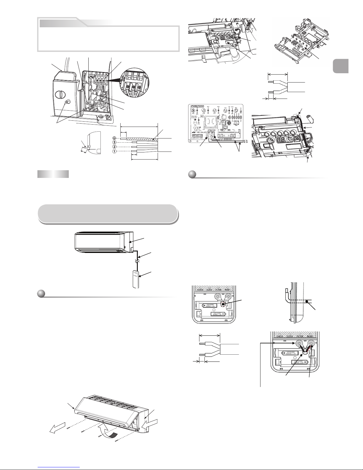
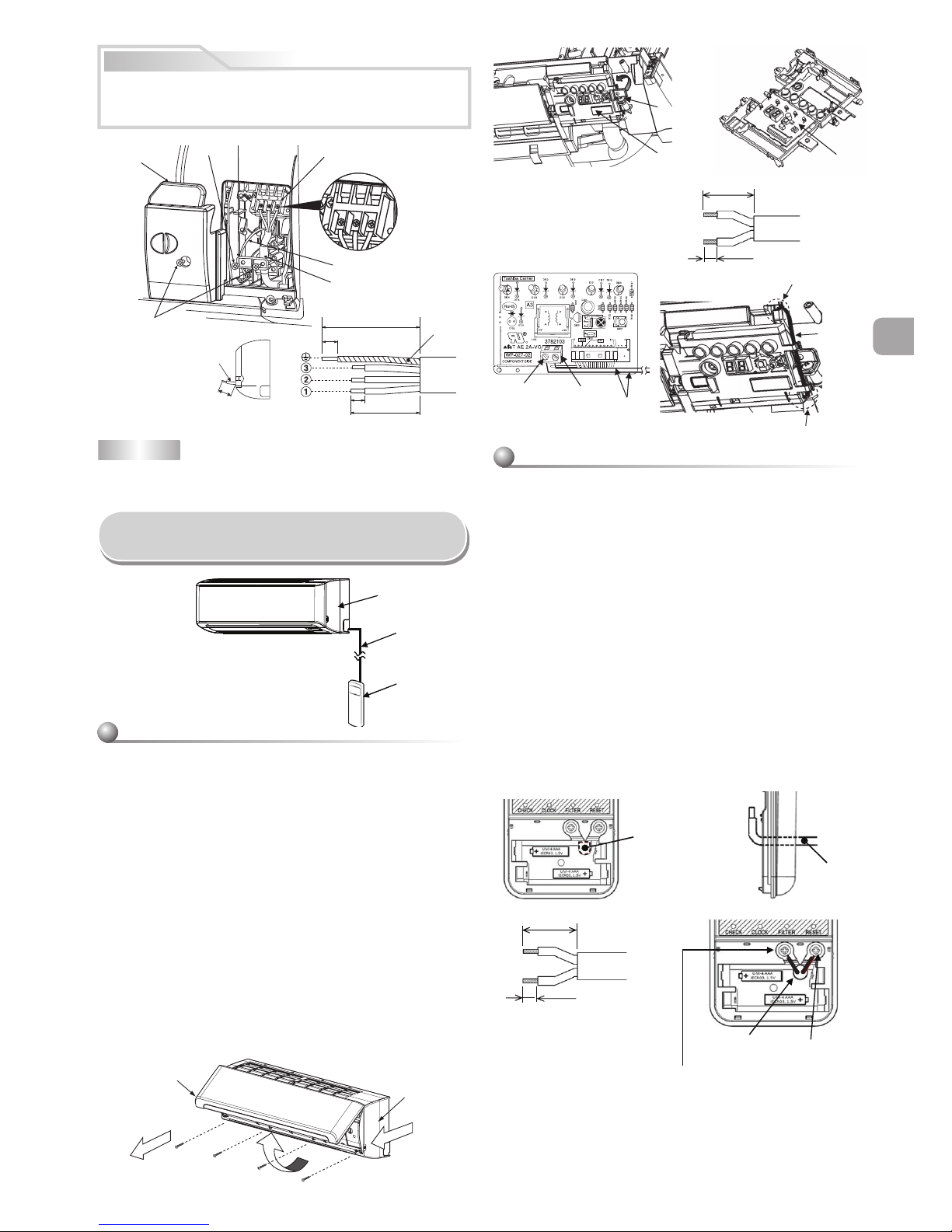
Wiring Connection
Wiring of the connecting cable can be carried out without removing the
front panel.
1. Remove the air inlet grille.
Open the air inlet grille upward and pull it toward you.
2. Remove the terminal cover and cord clamp.
3. Insert the connecting cable (according to the local rule) into the pipe hole
on the wall.
4. Take out the connecting cable through the cable slot on the rear panel so
that it protrudes about 15 cm from the front.
5. Insert the connecting cable fully into the terminal block and secure it tightly
with screws.
6. Tighten fi rmly but not over 1.2 N·m (0.12 kgf·m)
7. Secure the connecting cable with the cord clamp.
8. Fix the terminal cover, rear plate bushing and air inlet grille on the indoor
unit.
How to connect the connecting cable
EN
ES
FR
IT
DE
PT
PL
CZ
RU
CR
HU
TR
NL
GR
SV
FI
NO
DK
RO
BG
EE
LV
SK
SI
5
EN
• Be sure to refer to the wiring system diagram labeled inside the front
panel.
• Check local electrical cords and also any specifi c wiring instructions or
limitations.
NOTE
• Use stranded wire only.
• Wire type : More than 1.5 mm² (H07RN-F or 60245 IEC66) or 1.3 mm²
(AWG-16)
CAUTION
1
2
3
Cord clamp
Terminal block
Terminal cover
Screw
Earth line
Screw
Connecting cable
Earth line
Connecting cable
Stripping length of the connecting cable
about 15 cm
110 mm
80 mm
20 mm
10 mm
1. Open the air inlet grille upward.
2. Securely remove four screws at the front panel.
3. Slightly open the lower part of the front panel then pull the upper part of
the front panel toward you to remove it from the rear plate as shown on
fi gure 1.
4. After removing the front panel, remove the screws and Display unit from
the unit as shown on fi gure 2 then open the front cover of Display unit
as shown on fi gure 3.
5. Arrange the control wire as detail and specifi cation as shown on fi gure 4.
6. Securely connect the control wire to terminal of Display unit board as
shown on fi gure 5 (tighten fi rmly but not over 0.12 N·m (0.01 kgf·m)).
7. Set the control wire throughout at slot on front cover of Display unit then
reassembly Display with main casing by reverse process of fi gure 2 and
3. Make sure the control wire must not be pressed by front and rear
cover of Display unit.
8. Set the control wire out from indoor unit same portion as power supply
and connecting cable as shown on fi gure 6.
9. Reassembly the indoor unit by reverse process of 1 to 3.
Indoor unit
Control wire
Remote controller
How to Connect Remote Controller
for Wire Operation
For indoor unit
Air inlet grille
Front panel
1
Display board
23
Display unit
Remove screw
1. Remove cover of remote controller by sliding down and take it out.
2. If batteries are exist, please take them out. The combination of using
wire controller and batteries may cause of batteries explosion.
3. Make hole for insert control wire by use screwdriver break the polyester
sheet as shown on fi gure 7.
4. Insert control wire from rear side of remote controller as shown on
fi gure 8.
5. Fix control wire which arrange as shown on fi gure 9 and ! to terminal
by provided screws (tighten fi rmly but not over 0.25 N·m (0.03 kgf·m)).
6. Set control wire through gutter way at rear side of remote controller as
shown on fi gure ".
7. Fix provided screw (Ø3.1×16L) on the wall to hang remote controller as
shown on fi gure #.
8. Mark and arrange hole for fi x below screw (Ø3.1×25L) as shown on
fi gure #.
9. Assembly battery cover which provided with accessory bag then use
provide screw (Ø3.1×25L) to fi x battery cover together with wall as
shown on fi gure $ (tighten fi rmly but not over 0.15 N·m (0.02 kgf·m)).
10. Reassembly cover of remote controller.
For remote controller
CAUTION
• Be sure to install control wire along
the wall so that there is no slack and
fi x remote controller on the wall.
* Wire size 28-22 AWG (0.08-0.32 mm2)
Outer diameter not over 4.7 mm, control wire
length less than 30 m.
70 mm
5 mm
4
6
5
Terminal
Control wire
Control wire out position
Control wire through out position
Tighten fi rmly but
not over 0.12 N·m
(0.01 kgf·m)
Control wire
78
Polyester sheet
close hole for insert
control wire
Control wire
9!
Control wire
Terminal
* Wire size 28-22 AWG (0.08-0.32 mm2)
Outer diameter not over 4.7 mm,
control wire length less than 30 m.
30 mm
10 mm
Tighten fi rmly but not over
0.25 N·m (0.03 kgf·m)
6
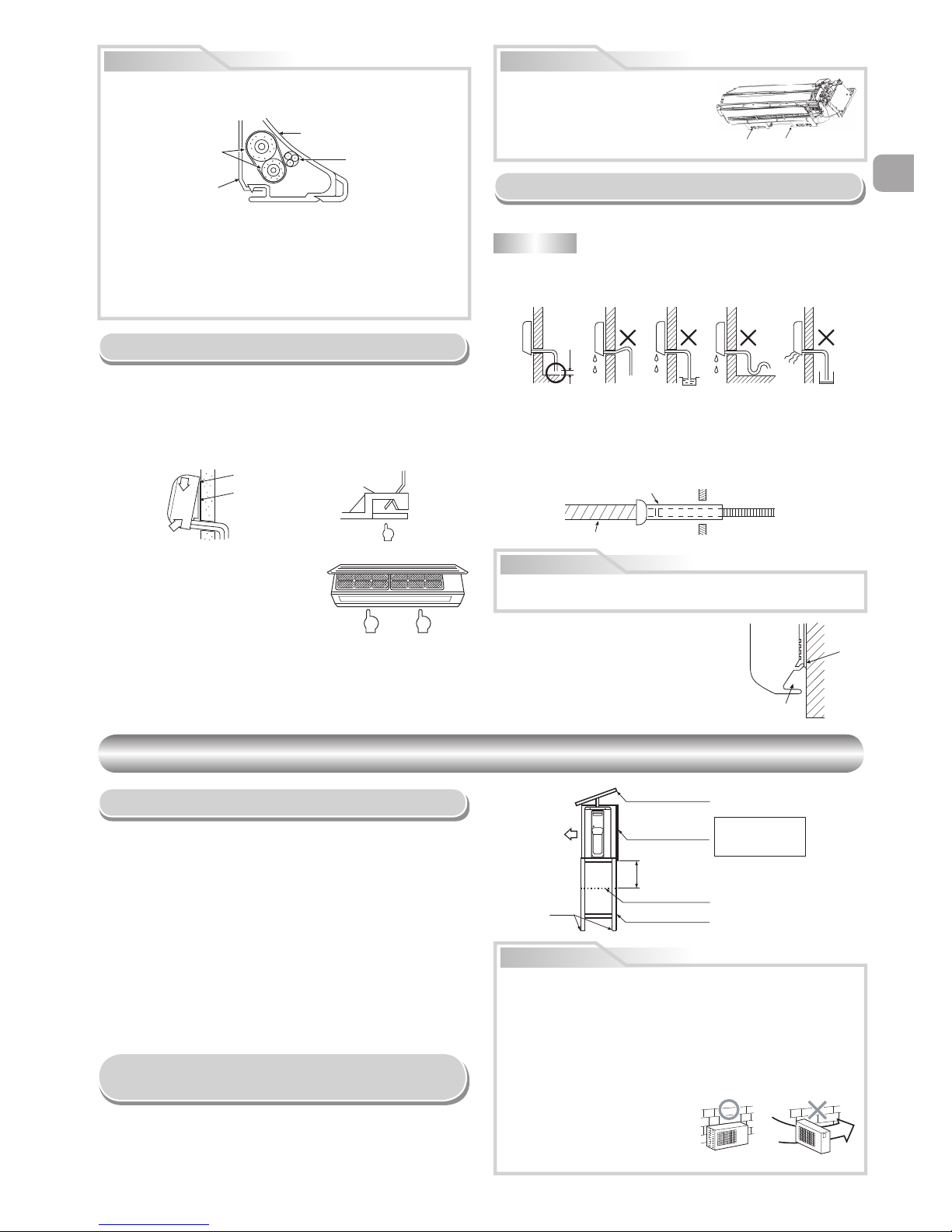
Piping and Drain Hose Installation
* Since dewing results in a machine trouble, make sure to insulate both
connecting pipes. (Use polyethylene foam as insulating material.)
Piping and drain hose forming
1. Die-cutting front panel slit
Cut out the slit on the leftward or right side of the front panel for the left
or right connection and the slit on the bottom left or right side of the front
panel for the bottom left or right connection with a pair of nippers.
2. Changing drain hose
For leftward connection, bottom-leftward connection and rearleftward
connection’s piping, it is necessary to change the drain hose and drain
cap.
How to remove the drain cap
Clip the drain cap by needle-nose
pliers and pull out.
How to remove the drain hose
• The drain hose can be removed by removing the
screw securing the drain hose and then pulling out
the drain hose.
• When removing the drain hose, be careful of any
sharp edges of steel plate. The edges can injuries.
• To install the drain hose, insert the drain hose
fi rmly until the connection part contacts with heat
insulator, and then secure it with original screw.
How to fi x the drain cap
1) Insert hexagon
wrench (4 mm)
in a center head.
2) Firmly insert the drain cap.
Firmly insert the drain hose and drain cap; otherwise, water may leak.
In case of right or left piping
• After scribing slits of the front panel with a
knife or a making-off pin, cut them with a
pair of nippers or an equivalent tool.
In case of bottom right or bottom left piping
• After scribing slits of the front panel with a
knife or a making-off pin, cut them with a
pair of nippers or an equivalent tool.
Left-hand connection with piping
• Bend the connecting pipe so that it is laid within 43 mm above the wall
surface. If the connecting pipe is laid exceeding 43 mm above the wall
surface, the indoor unit may unstably be set on the wall.
When bending the connecting pipe, make sure to use a spring bender so as
not to crush the pipe.
Bend the connecting pipe within a radius of 30 mm.
To connect the pipe after installation of the unit (fi gure)
How to install the air inlet grille on the indoor
unit
• When attaching the air inlet grille,
perform the same process as for
removal but in reverse order.
CAUTION
80
Liquid side
Gas side
(To the forefront of fl are)
Outward form of indoor unit
R 30 mm (Use polisin (polyethylene)
core or the like for bending pipe.)
Use the handle of screwdriver, etc.
Rear right
Rear left
Bottom left
Left
Bottom right
Right
Die-cutting
front panel slit
Changing
drain hose
Piping preparation
Heat insulator
Drain hose
4 mm
No gap
Do not apply lubricating oil
(refrigerant machine oil) when
inserting the drain cap. Application
causes deterioration and drain
leakage from the plug.
Insert a hexagon
wrench (4 mm).
Slit
Slit
520 mm
420 mm
43 mm
Control wire
Hole for hang
remote controller
Remote controller
Control wire
Screw (Ø3.1×16L)
for hang remote
controller
Wall
Screw (Ø3.1×25L)
for fi x battery cover
Remote controller
"#
*Remark : 1. Recommend to use double insulation lead wire for connect
remote control and air conditioner.
2. For wire operation, 1 remote control can control only 1 indoor
unit.
3. In wire operation, remote controller will return to initial
condition (PRESET, TIMER and CLOCK will return to
initial condition) when user shutdown power supply of air
conditioner.
$
Battery cover
Screw
Tighten fi rmly but not over
0.15 N·m (0.02 kgf·m)
NOTE
If the pipe is bent incorrectly, the indoor unit may unstably be set on the wall.
After passing the connecting pipe through the pipe hole, connect the
connecting pipes to the auxiliary pipes and wrap the facing tape around
them.
EN
ES
FR
IT
DE
PT
PL
CZ
RU
CR
HU
TR
NL
GR
SV
FI
NO
DK
RO
BG
EE
LV
SK
SI
7
EN
CAUTION
Indoor Unit Fixing
• For detaching the indoor unit from the
installation plate, pull the indoor unit
toward you while pushing its bottom up at
the specifi ed parts.
1
2
1
1. Pass the pipe through the hole in the wall and hook the indoor unit on the
installation plate at the upper hook.
2. Swing the indoor unit to right and left to confi rm that it is fi rmly hooked up
on the installation plate.
3. While pressing the indoor unit onto the wall, hook it at the lower part on the
installation plate. Pull the indoor unit toward you to confi rm that it is fi rmly
hooked up on the installation plate.
Drainage
1. Run the drain hose sloped downwards.
2. Put water in the drain pan and make sure that the water is drained out of
doors.
3. When connecting extension drain hose, insulate the connecting part of
extension drain hose with shield pipe.
NOTE
• The hole should be made at a slight downward slant on the outdoor side.
Arrange the drain pipe for proper drainage from the unit.
Improper drainage can result in dew-dropping.
This air conditioner has the structure designed
to drain water collected from dew, which forms
on the back of the indoor unit, to the drain pan.
Therefore, do not store the power cord and other
parts at a height above the drain guide.
CAUTION
OUTDOOR UNIT
OUTDOOR UNIT
Installation Place
• A place which provides enough spaces around the outdoor unit as shown in
the diagram
• A place which can bear the weight of the outdoor unit and does not allow an
increase in noise level and vibration
• A place where the operation noise and discharged air do not disturb your
neighbors
• A place which is not exposed to a strong wind
• A place free of a leakage of combustible gases
• A place which does not block a passage
• When the outdoor unit is to be installed in an elevated position, be sure to
secure its feet.
• An allowable length of the connecting pipe is up to 20 m.
• There is no need to add refrigerant as long as the length of the connection
piping is 15 m or less.
• You will need to add 20g of refrigerant per meter of added connection piping
for installations requiring connection piping to be between 16 m to 20 m.
• An allowable height level is up to 10 m.
• A place where the drain water does not cause any problems
CAUTION
1. Install the outdoor unit in a location where there are no obstructions near
its air intake or air outlet.
2. When the outdoor unit is installed in a place that is always exposed to
strong winds like on the coast or on a high story of a building, secure the
normal fan operation using a duct or a wind shield.
3. Especially in windy areas, install the unit to prevent the admission of wind.
4. Installation in the following places may result in trouble. Do not install the
unit in such places.
• A place full of machine oil.
• A saline-place such as the coast.
• A place full of sulfi de gas.
• A place where high-frequency
waves are likely to be generated,
such as from audio equipment,
welders, and medical equipment.
• Do not use the supplied drain nipple for draining water. Drain the water from
all the drain holes directly.
• To protect the outdoor unit from snow accumulation, install a holding frame,
and attach a snow protection hood and plate.
* Do not use a double-stacked design.
Precautions about Installation in Regions
with Snowfall and Cold Temperatures
• Bind the auxiliary pipes (two) and connecting cable with facing tape
tightly. In case of leftward piping and rear-leftward piping, bind the
auxiliary pipes (two) only with facing tape.
Indoor unit
Connecting cable
Auxiliary pipes
Installation plate
• Carefully arrange pipes so that any pipe does not stick out of the rear
plate of the indoor unit.
• Carefully connect the auxiliary pipes and connecting pipes to one
another and cut off the insulating tape wound on the connecting pipe
to avoid double-taping at the joint; moreover, seal the joint with the
vinyl tape, etc.
• Since dewing results in a machine trouble, make sure to insulate both
connecting pipes. (Use polyethylene foam as insulating material.)
• When bending a pipe, carefully do it, not to crush it.
The lower part of indoor unit may fl oat,
due to the condition of piping and you
cannot fi x it to the installation plate. In
that case, use the % screws provided to
fi x the unit and the installation plate.
Information
%
Screw% Screw
Hook here.
Installation plate
Hook
Press
(unhook)
Push Push
Do not rise the
drain hose.
Do not form the
drain hose into
a wavy shape.
50 mm
or more
Do not put the
drain hose end
into water.
Do not put the
drain hose end
in the drainage ditch.
Shield pipe
Drain hose
Extension drain hose
Inside the room
Wall
Drain
guide
Space for pipes
Snow protection plate
Snow protection hood
At least
50 cm
Snow accumulation line
Holding frame
Front
Anchor
bolts
Install at least 50 cm
above the snow
accumulation line.
Strong
wind
8
A
90
CAUTION
Refrigerant Piping Connection
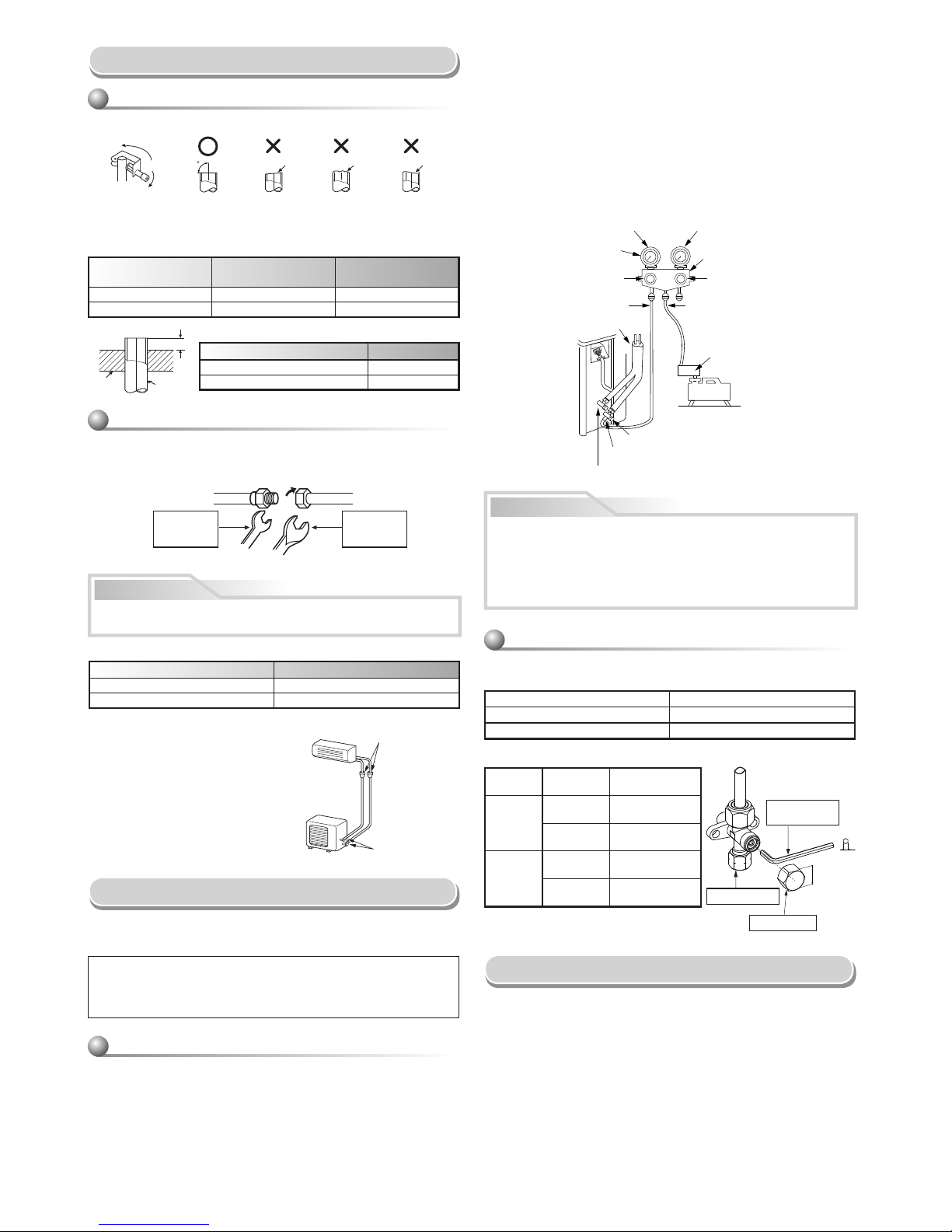
1. Cut the pipe with a pipe cutter.
2. Insert a fl are nut into the pipe and fl are the pipe.
• Projection margin in fl aring : A (Unit : mm)
Rigid (clutch type)
Imperial (wing nut type)
Outer dia. of copper pipe R410A
Ø6.35 mm 1.5 to 2.0
Ø12.70 mm 2.0 to 2.5
Align the centers of the connecting pipes and tighten the fl are nut as far as
possible with your fi ngers. Then tighten the nut with a spanner and torque
wrench as shown in the fi gure.
Tightening connection
Do not apply excess torque. Otherwise, the nut may crack depending on
the conditions.
(Unit : N·m)
Outer dia. of copper pipe Tightening torque
Ø6.35 mm 14 to 18 (1.4 to 1.8 kgf·m)
Ø12.70 mm 50 to 62 (5.0 to 6.2 kgf·m)
Evacuating
After the piping has been connected to the indoor unit, you can perform
vacuuming together at once.
VACUUMING
Evacuate the air in the connecting pipes and in the indoor unit using a
vacuum pump. Do not use the refrigerant in the outdoor unit. For details,
see the manual of the vacuum pump.
Outer dia.
of copper pipe
R410A tool used
Conventional tool
used
Ø6.35 mm 0 to 0.5 1.0 to 1.5
Ø12.70 mm 0 to 0.5 1.0 to 1.5
• Tightening torque for connection of fl are pipe
The pressure of R410A is higher than
R22. (Approx. 1.6 times.) Therefore
securely tighten the fl are pipes which
connect the outdoor unit and the
indoor unit with the specifi ed tightening
torque using a torque wrench. If any
fl are pipe is incorrectly connected, it
may cause not only a gas leakage but
also trouble in the refrigeration cycle.
Flaring
1. Connect the charge hose from the manifold valve to the service port of
the packed valve at gas side.
2. Connect the charge hose to the port of the vacuum pump.
3. Open fully the low pressure side handle of the gauge manifold valve.
4. Operate the vacuum pump to start evacuating. Perform evacuating for
about 15 minutes if the piping length is 20 meters. (15 minutes for 20
meters) (assuming a pump capacity of 27 liters per minute) Then confi rm
that the compound pressure gauge reading is –101 kPa (–76 cmHg).
5. Close the low pressure side valve handle of the gauge manifold valve.
6. Open fully the valve stem of the packed valves (both gas and liquid sides).
7. Remove the charging hose from the service port.
8. Securely tighten the caps on the packed valves.
Packed valve at liquid side
Service port (Valve core (Setting pin))
Packed valve at gas side
Vacuum
pump
Vacuum pump adapter for
counter-fl ow prevention
(For R410A only)
Charge hose
(For R410A only)
Handle Hi
(Keep full closed)
Manifold valve
Pressure gauge
Compound pressure gauge
Handle Lo
Charge hose
(For R410A only)
Connecting pipe
–101 kPa
(–76 cmHg)
• KEEP IMPORTANT 5 POINTS FOR PIPING WORK.
(1) Take away dust and moisture (inside of the connecting pipes).
(2) Tighten the connections (between pipes and unit).
(3) Evacuate the air in the connecting pipes using a VACUUM PUMP.
(4) Check gas leak (connected points).
(5) Be sure to fully open the packed valves before operation.
CAUTION
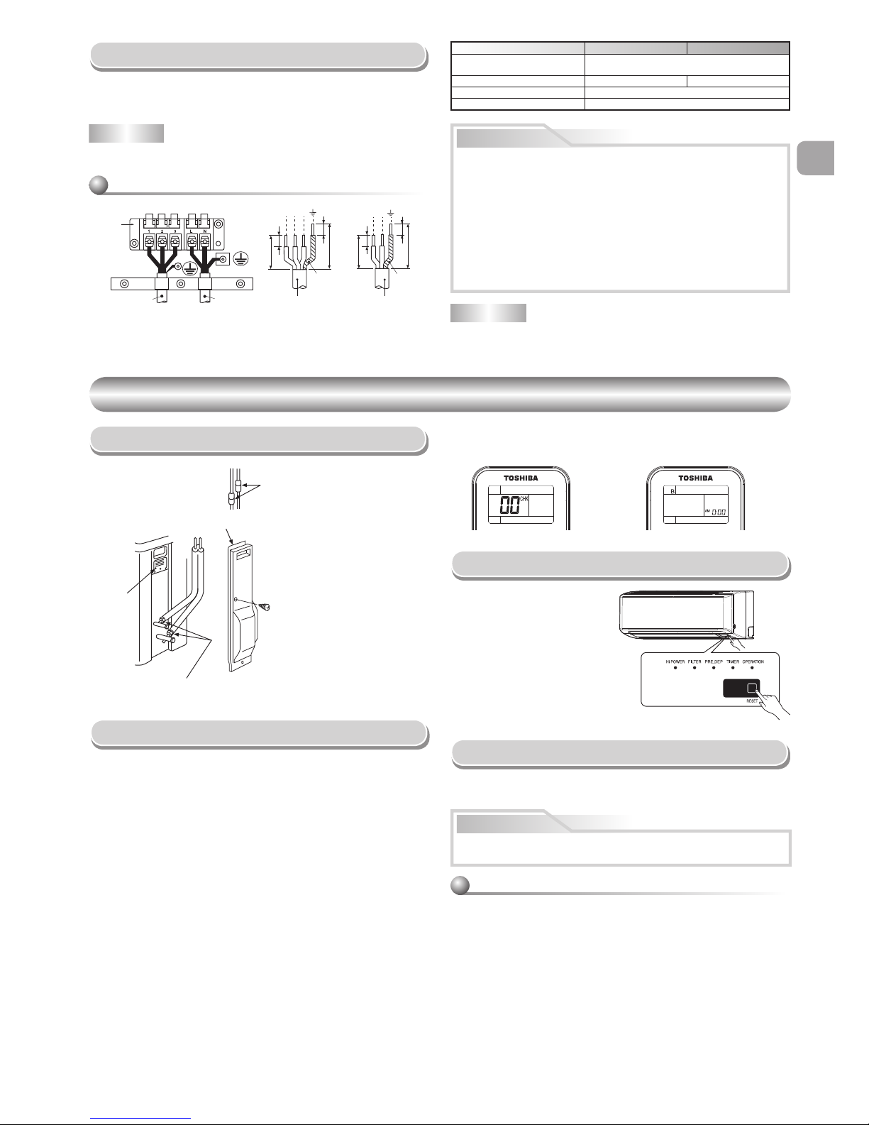
Wiring Connection
1. Remove the valve cover, the electric parts cover and the cord clamp from
the outdoor unit.
2. Connect the connecting cable to the terminal as identifi ed by the
matching numbers on the terminal block of indoor and outdoor unit.
3. Insert the power cord and the connecting cable fully into the terminal
block and secure it tightly with screws.
4. Use vinyl tape, etc. to insulate the cords which are not going to be used.
Locate them so that they do not touch any electrical or metal parts.
5. Secure the power cord and the connecting cable with the cord clamp.
6. Attach the electric parts cover and the valve cover on the outdoor unit.
Be sure to use a vacuum pump with counter-fl ow prevention function so
that inside oil of the pump does not fl ow backward into pipes of the air
conditioner when the pump stops.
(If oil inside of the vacuum pump enters the air conditioner, which use
R410A, refrigeration cycle trouble may happen.)
Using a vacuum pump
Obliquity Roughness Warp
Half union Flare nut
Externally
threaded side
Internally
threaded side
Pipe
Die
Flare at
indoor unit side
Flare at
outdoor unit side
Use a wrench to secure. Use a torque wrench to tighten.
Packed valve handling precautions
• Open the valve stem all the way out, but do not try to open it beyond the
stopper.
• Securely tighten the valve cap with torque in the following table:
Pipe size of Packed Valve Size of Hexagon wrench
12.70 mm and smallers A = 4 mm
15.88 mm A = 5 mm
A
H
Hexagon wrench
is required.
Cap
Cap Size
(H)
Torque
Valve Rod
Cap
H17 - H19
14~18 N·m
(1.4 to 1.8 kgf·m)
H22 - H30
33~42 N·m
(3.3 to 4.2 kgf·m)
Service
Port Cap
H14
8~12 N·m
(0.8 to 1.2 kgf·m)
H17
14~18 N·m
(1.4 to 1.8 kgf·m)
Service Port Cap
Valve Rod Cap
EN
ES
FR
IT
DE
PT
PL
CZ
RU
CR
HU
TR
NL
GR
SV
FI
NO
DK
RO
BG
EE
LV
SK
SI
9
EN
Electrical Work
1. The supply voltage must be the same as the rated voltage of the air
conditioner.
2. Prepare the power source for exclusive use with the air conditioner.
NOTE
• Wire type : H07RN-F or 60245 IEC66 (1.5 mm2 or more)
OTHERS
OTHERS
Gas Leak Test
Test Operation
To switch to the TEST RUN
(COOL) mode, press [RESET]
button for 10 seconds.
(The beeper will make a short
beep.)
Auto Restart Setting
The product was shipped with Auto Restart function in the off position.
Turn it on as required.
How to set the Auto Restart
Remote Control A-B Selection
To separate using of remote control for each indoor unit in case of 2 air
conditioners are installed near.
Remote Control B Setup.
1. Press [RESET] button on the indoor unit to turn the air conditioner ON.
2. Point the remote control at the indoor unit.
3. Push and hold [CHECK] button on the Remote Control by the tip of the
pencil. “00” will be shown on the display (Picture 1).
4. Press [MODE] during pushing [CHECK]. “B” will show on the display
and “00” will disappear and the air conditioner will turn OFF. The Remote
Control B is memorized (Picture 2).
• When two indoor units are installed in the same room or adjacent two
rooms, if operating a unit, two units may receive the remote control signal
simultaneously and operate. In this case, the operation can be preserved
by setting either one remote control to B setting. (Both are set to A setting
in factory shipment.)
• The remote control signal is not received when the settings of indoor unit
and remote control are different.
• There is no relation between A setting/B setting and A room/B room when
connecting the piping and cables.
• Check the fl are nut connections
for the gas leak with a gas leak
detector or soap water.
This product is designed so that, after a power failure, it can restart
automatically in the same operating mode as before the power failure.
1. Press and hold the [RESET] button on the indoor unit for 3 seconds to
set the operation. (3 beep sound and OPERATION lamp blink 5 time/sec
for 5 seconds)
2. Press and hold the [RESET] button on the indoor unit for 3 seconds to
cancel the operation. (3 beep sound but OPERATION lamp does not
blink)
• In case of ON timer or OFF timer are set, AUTO RESTART
OPERATION does not activate.
Stripping length of the connecting cable
Model 18 class 22 class
Power source
220 – 240 V Single phase, 50Hz
220 V Single phase, 60Hz
Maximum running current 10.0A 13.5A
Plug socket & fuse rating 16A
Power cord H07RN-F or 60245 IEC66 (1.5 mm
2
or more)
NOTE : Connecting cable
• Wire type : More than 1.5 mm² (H07RN-F or 60245 IEC66) or 1.3 mm²
(AWG-16)
• Wrong wiring connection may cause some electrical parts burn out.
• Be sure to comply with local rule on running the wire from indoor unit
to outdoor unit (size of wire and wiring method, etc.).
• Every wire must be connected fi rmly.
• If incorrect or incomplete wiring is carried out, it will cause an ignition
or smoke.
• Prepare the power supply for exclusive use with the air conditioner.
• This product can be connected to the mains.
Connection to fi xed wiring: A switch which disconnects all poles and
has a contact separation of at least 3 mm must be incorporated in the
fi xed wiring.
CAUTION
Check places for
the indoor unit.
Electric parts
cover
Check places for
the outdoor unit.
Valve cover
Information
10
10
10
30
30
40
40
L
N
1
2
3
10
Connecting
cable
Power cord
Terminal
block
Earth line Earth line
Connecting cable Power cord
12
RESET button
Note : 1. Repeat above step to reset Remote Control to be A.
2. Remote Control A has not “A” display.
3. Default setting of Remote Control from factory is A.
w When using a multi-system outdoor unit is used, refer to the installation
manual provided with the model concerned.
AIR CONDITIONER (SPLIT TYPE)
INSTALLATION MANUAL
1110651195
Indoor unit
RAS-(B)18, 22N3KV2 Series
RAS-M24N3KV2 Series
Outdoor unit
RAS-18, 22N3AV2 Series
RAS-3M26UAV-E
RAS-4M27UAV-E
RAS-5M34UAV-E1
DEUTSCH

SICHERHEITSVORKEHRUNGEN .....................................................................................................................................1
EINBAUZEICHNUNGEN FÜR INNEN- UND AUSSENGERÄT .........................................................................................3
Zusätzlich erhältliche Installationsteile ...........................................................................................................................3
INNENGERÄT .....................................................................................................................................................................4
Aufstellungsort ................................................................................................................................................................4
Mauerdurchbruch und Befestigung der Montageplatte ..................................................................................................4
Kabelanschlüsse .............................................................................................................................................................4
Verbindung der Fernbedienung zur Funktion per Kabelanschluss. ................................................................................5
Installation von Leitungen und Kondensatschlauch ........................................................................................................6
Einbau des Innengeräts ..................................................................................................................................................7
Entwässerung ................................................................................................................................................................7
AUSSENGERÄT .................................................................................................................................................................7
Aufstellungsort ................................................................................................................................................................7
Vorsichtsmaßnahmen beim Einbau in Regionen mit Schneefall und kalten Temperaturen ............................................7
Anschluß der Kühlmittelleitungen ...................................................................................................................................8
Entleeren ........................................................................................................................................................................8
Kabelanschlüsse .............................................................................................................................................................8
Elektrische Anschlüsse ..................................................................................................................................................9
SONSTIGES........................................................................................................................................................................9
Überprüfung auf Gas-Undichtigkeit .................................................................................................................................9
Fernbedienung A-B Wahl ................................................................................................................................................9
Probelauf .........................................................................................................................................................................9
Automatische Wiedereinschaltung ..................................................................................................................................9
INHALT
DE
EN
ES
FR
DE
DE
PT
PL
CZ
RU
CR
HU
TR
NL
GR
SV
FI
NO
DK
RO
BG
EE
LV
SK
SI
1
SICHERHEITSVORKEHRUNGEN
SICHERHEITSVORKEHRUNGEN
Installation einer Klimaanlage mit neuartigem Kühlmittel
VORSICHT
•
IN DIESER KLIMAANLAGE WIRD DAS NEUARTIGE HFC-KÜHLMITTEL (R410A) VERWENDET, DAS DIE OZONSCHICHT NICHT SCHÄDIGT.
Das Kühlmittel R410A ist anfällig für Verunreinigungen durch Wasser, Membranoxidation und Öle, da der Druck des Kühlmittels R410A etwa das 1,6
fache des Drucks beim Kühlmittel R22 beträgt. Zusammen mit dem neuen Kühlmittel wird nun auch ein anderes Kälteanlagenöl verwendet. Achten Sie bei
der Installation deshalb darauf, daß kein Wasser, Staub, altes Kühlmittel oder altes Kälteanlagenöl in den Kühlkreislauf der Klimaanlage mit dem neuen
Kühlmittel gerät.
Damit es nicht zu einer Vermischung von Kühlmittel und Kälteanlagenöl kommt, haben die Anschlüsse an den Einfüllöffnungen des Hauptgeräts bzw. die
Installationswerkzeuge eine andere Größe als bei herkömmlichen Kühlmitteln. Verwenden Sie für die Anschlußleitungen neues Spezialleitungsmaterial
für R410A, das frei von Verunreinigungen ist und hohem Druck standhält, so daß Wasser oder Staub nicht eindringen können. Verwenden Sie auch nicht
die vorhandenen Leitungen, da diese nicht auf den höheren Druck ausgelegt sind und Verunreinigungen enthalten können.
Zur allgemeinen Verwendung bestimmt
Stromversorgungskabel für das Außengerät müssen für den Einsatz im Freien zumindest mit einer Isolierung aus polychloropren ummantelt sein (design
H07RN-F) bzw. die Norm 60245 IEC66 erfüllen (1,5 mm2 oder mehr). (Die Installation muss in Übereinstimmung mit den örtlichen Vorschriften zur Installation
elektrischer Geräte erfolgen.)
• Lesen Sie bitte vor dem Einbau diese Anweisungen für Sicherheitsvorkehrungen genau durch.
• Befolgen Sie diese Vorsichtsmaßnahmen, um Gefährdungen auszuschließen. Die Symbole und ihre Bedeutung sind nachstehend aufgeführt.
WARNUNG : Bedeutet, dass die falsche Verwendung dieses Gerätes u. U. tödliche Verletzungen verursachen kann.
VORSICHT : Bedeutet, dass die falsche Verwendung dieses Gerätes Verletzungen (*1) oder Sachschäden (*2) verursachen kann.
*1 : Verletzungen bezeichnet leichte Unfälle, Verbrennungen oder Stromschläge, die keine Behandlung im Krankenhaus erfordern.
*2 : Sachschäden bedeutet größere Schäden an Anlagen und Material.
GEFAHR
• DIESES GERÄT IST NUR ZUR VERWENDUNG DURCH HIERZU BEFUGTE PERSONEN BESTIMMT.
• VOR ARBEITEN AN DER ANLAGE IST UNBEDINGT DIE STROMZUFUHR ZU UNTERBRECHEN. VERGEWISSERN SIE SICH, DASS ALLE SCHALTER
UND SICHERUNGEN AUSGESCHALTEN SIND. WIRD DIES NICHT BEACHTET KANN EIN STROMSCHLAG DIE FOLGE SEIN.
•
ACHTEN SIE DARAUF DASS ALLE ELEKTROKABEL ORDNUNGSGEMÄß ANGESCHLOSSEN SIND. INKORREKTER ANSCHLUSS KANN BESCHÄDIGUNGEN
DER ELEKTRISCHEN BAUTEILE ZUR FOLGE HABEN.
• VERGEWISSERN SIE SICH BEI DER MONTAGE AUF ORDNUNGSGEMÄßE ERDUNG DES GERÄTES.
• DAS GERÄT NICHT AN ORTEN MIT BRENNBAREN GASEN ODER DÄMPFEN INSTALLIEREN.
BRAND ODER EXPLOSION KÖNNTE DIE FOLGE SEIN.
• UM EINER ÜBERHITZUNG DES INNENGERÄTES UND DER DAMIT VERBUNDENEN BRANDGEFAHR ZU VERHINDERN, IST DARAUF ZU ACHTEN
DAS GERÄT IN AUSREICHENDEM ABSTAND (2 M) VON WÄRMEQUELLEN WIE HEIZKÖRPERN UND STRAHLERN, ÖFEN, ETC. AUFZUSTELLEN.
• WIRD DAS KLIMAGERÄT IN EINEN ANDEREN RAUM UMMONTIERT IST UNBEDINGT DARAUF ZU ACHTEN, DASS KEINE ANDEREN STOFFE MIT
DEM KÄLTEMITTEL (R410A) IN KONTAKT KOMMEN. SOLLTE LUFT ODER ANDERE GASE IN DEN KÄLTEKREISLAUF GELANGEN, KANN DIES ZUM
ÜBERMÄßIGEN ANSTEIGEN DES BETRIESBSDRUCKES, ZUM PLATZEN VON LEITUNGEN UND DAMIT ZU VERLETZUNGEN FÜHREN.
• SOLLTEN BEI MONTAGEARBEITEN GRÖßERE MENGEN KÄLTEMITTEL AUS EINER DER LEITUNGEN ENTWEICHEN, SO SOLLTEN DIE ARBEITEN
SOFORT UNTERBROCHEN UND DIE RÄUME GUT DURCHLÜFTET WERDEN. BEI ERHITZUNG DES ENTWICHENEN KÄLTEMITTELS DURCH EINE
FLAMME O.Ä. BILDEN SICH GESUNDHEITSSCHÄDLICHE SUBSTANZEN.

2
MELDEPFLICHT AN DAS ÖRTLICHE ENERGIEVERSORGUNGSUNTERNEHMEN
Unbedingt die Installation dieser Anlage vor der Aufstellung dem örtlichen Stromversorger anzeigen. Im Falle von Problemen oder falls die Installation vom
Stromversorger nicht genehmigt wird, sorgt der Kundendienst für Abhilfe.
VORSICHT
• Kontakt der Anlage mit Wasser oder Feuchtigkeit vor der Installation kann elektrische Schläge zur Folge haben.
Das Gerät nicht in einem feuchten Keller lagern; unbedingt die Geräte vor Regen und Feuchtigkeit schützen.
• Nach dem Auspacken den Einbausatz sorgfältig auf Beschädigung überprüfen.
• Das Gerät darf nicht an einem Ort aufgestellt werden, an dem Vibrationen vorhanden sind. Das Gerät keinesfalls an Orten aufstellen, an denen sich das
Betriebsgeräusch verstärken kann bzw. an denen Nachbarn durch Geräusch und Abluft belästigt werden könnten.
• Bitte lesen Sie vor dem Einbau des Gerätes diese Einbauanleitung sorgfältig durch. Sie enthält weitere wichtige Anweisungen für den korrekten Einbau.
• Je nach Einbauort muss dieses Gerät über einen Schutzschalter an das Stromnetz angeschlossen werden. Die Nichtbefolgung dieser Vorschrift kann zu
Stromschlägen führen.
• Befolgen Sie bei der Verlegung des Abfl ussrohres die Anweisungen dieser Einbauanleitung, um den korrekten Wasserabfl uss aus dem Gerät sicherzustellen.
Stellen Sie sicher, dass das abgeschiedene Wasser in einen Abfl uss geleitet wird. Ein unzureichender Abfl uss kann zum Austritt von Wasser führen, das
Möbel beschädigen könnte.
• Ziehen Sie die Überwurfmutter vorschriftsmäßig mit einem Drehmomentschlüssel an. Ziehen Sie die Mutter nicht zu fest an. Sie könnte sonst nach einiger
Zeit reißen, und Kühlmittel könnte austreten.
• Tragen Sie bei den Einbauarbeiten Handschuhe, z.B. feste Arbeitshandschuhe aus Baumwolle. Die Nichtbefolgung kann zu Verletzungen beim Umgang mit
scharfkantigen Teilen führen.
• Berühren Sie nicht den Luftansaugstutzen oder die Aluminium-Leitbleche des Außenmoduls. Sie könnten sich verletzen.
• Bauen Sie das Außenmodul nicht an einem Ort ein, an dem kleine Tiere darin nisten könnten. Kleine Tiere könnten ins Geräteinnere eindringen und mit
stromführenden Teilen in Berührung kommen, was einen Ausfall der Anlage oder einen Brand verursachen könnte.
• Bitten Sie den Betreiber der Anlage, die Umgebung sauber und ordentlich zu halten.
• Führen Sie unbedingt nach dem Einbau einen Probelauf der Anlage durch, und unterweisen Sie den Betreiber in deren vorschriftsgemäßen Betrieb und
Wartung. Bitten Sie den Kunden, die Einbauanleitung zusammen mit der Betriebsanleitung zu verwahren.
• Der Hersteller übernimmt keine Haftung für die Schäden, die durch Nichtbeachtung der Beschreibung in dieser Bedienungsanleitung verursacht werden.
WARNUNG
• Dieses Gerät darf niemals so modifi ziert werden, daß die Sicherheitseinrichtungen durch Verändern der Sperrschalter deaktiviert werden.
• Mit dem Einbau muss der Lieferant oder ein qualifi zierter Handwerker beauftragt werden. Selbsteinbau kann zu undichten Wasserleitungen,
Stromschlägen oder Bränden führen.
• Die vorgeschriebenen Werkzeuge und Rohrleitungsteile für das Modell R410A sind erforderlich, und der Einbau muss gemäß dieser Anleitung
erfolgen. Das HFC Kühlmittel R410A hat einen gegenüber dem konventionellen Kühlmittel R22 um das 1,6-fache höheren Druck Verwenden Sie die
vorgeschriebenen Rohrleitungsteile und sorgen Sie für den korrekten Einbau, um Verletzungen und/oder Sachschäden zu vermeiden. So vermeiden
Sie Wasseraustritt, Stromschläge und Brände.
• Vergewissern Sie sich, dass das Gerät an einer für dessen Gewicht ausreichend tragfähigen Konstruktion montiert wird. Wird das Gerät an einer nicht
ausreichend tragfähigen Unterkonstruktion oder sonstwie falsch montiert, kann es herabstürzen und Verletzungen verursachen.
• Die elektrischen Anschlüsse müssen von einem qualifi zierten Handwerker in Übereinstimmung mit den geltenden gesetzlichen und fachlichen
Vorschriften und dieser Einbauanleitung durchgeführt werden. Ein eigener Stromkreis mit der dem Gerät entsprechenden Spannung ist erforderlich. Zu
schwache Leitungen, unzureichende Stromversorgung und fehlerhafter Anschluss können zu Stromschlägen und Bränden führen.
• Verwenden Sie zur Verbindung der Anschlüsse der Innen- und Außenmodule vorschriftsmäßig isolierte Kabel. Anschlüsse mit Zwischenverbindungen,
Litzendrähten und Einzeldrähten sind dafür nicht erlaubt. Fehlerhafter Anschluss oder fehlerhafte Verlegung können zu Bränden führen.
• Die Verkabelung zwischen den Innen- und Außenmodulen muss so verlegt werden, dass sich die Gerätedeckel problemlos schließen lassen. Falsche
Installation der Deckel kann zu Überhitzung, Bränden oder Stromschlägen im Bereich der Anschlussklemmen führen.
• Verwenden Sie ausschließlich das zugelassene Zubehör und die vorgeschriebenen Teile. Die Nichtbeachtung dieser Anweisung kann zum Ausfall der
Anlage, Wasseraustritt oder Stromschlägen führen.
• Nach Abschluss der Einbauarbeiten ist die Dichtheit des Kühlmittelkreislaufs zu prüfen. Tritt Kühlmittel in einem geschlossenen Raum aus und kommt
es mit einer Wärmequelle in Berührung, z.B. Heizlüfter oder Küchenherd, entstehen giftige Gase.
• Stellen Sie sicher, dass die Anlage ordnungsgemäß geerdet ist. Der Erdungsleiter darf nicht an einem Gasrohr, einer Wasserleitung, einem Blitzableiter
oder einer Telefonleitungs-Erdung angeklemmt werden. Unsachgemäße Erdung kann zu Stromschlägen führen.
• Das Gerät darf nicht an Stellen eingebaut werden, an denen brennbares Gas austreten könnte. Eine Ansammlung brennbaren Gases in der Umgebung
des Gerätes kann zu einem Brand oder einer Explosion führen.
• Das Gerät darf nicht in Feucht- oder Nassräumen wie Badezimmern oder Waschküchen eingebaut werden. Schäden an der elektrischen Isolierung
könnten zu Stromschlägen oder Bränden führen.
• Der Einbau muss gemäß den Vorschriften dieser Einbauanleitung erfolgen. Unsachgemäßer Einbau kann zu Wasseraustritt, Stromschlägen und
Bränden führen. Überprüfen Sie vor der Inbetriebnahme des Geräts die folgenden Punkte:
- Die Rohrleitungen müssen sinnvoll verlegt und dicht sein.
- Der Betriebshahn muss offen sein. Bei geschlossenem Hahn droht Überdruck, der zu Schäden am Kompressor führen kann. Kommt es gleichzeitig zu
einem Leck in den Anschlüssen, kann Luft angesaugt werden oder Überdruck entstehen, was zu Verletzungen und/oder Schäden am Gerät führen kann.
• Zum Abpumpen des Kühlmittels muss vor Entfernen der Kühlmittelleitung der Kompressor abgeschaltet werden. Das Entfernen der Kühlmittelleitung
bei laufendem Kompressor und geöffnetem Betriebshahn kann zum ansaugen von Luft und Überdruck im System führen, was Schäden am Gerät und
Verletzungen verursachen kann.
• Verändern Sie nicht das Anschlusskabel, schließen Sie es nicht an einer Verlängerung an und verwenden Sie kein Verlängerungskabel mit
Mehrfachverteiler. Dies kann zu Kontaktausfällen, Schäden an der Isolierung und Überstrom führen, was Brände und Stromschläge verursachen kann.
• Der Einbau des Geräts muß in Übereinstimmungen mit den für das betreffende Land geltenden Verkabelungsvorschriften erfolgen.
Bauen Sie das Gerät nicht ein, wenn Sie eine Beschädigung festgestellt haben. Fragen Sie sofort Ihren Fachhändler.
• Verwenden Sie kein anderes als das vorgeschriebene Kältemittel zum Nachfüllen oder Ersetzen.
Andernfalls kann anormal hoher Druck im Kühlkreislauf erzeugt werden, was zu einem Versagen oder einer Explosion des Produkts oder Verletzungen
führen kann.
EN
ES
FR
DE
DE
PT
PL
CZ
RU
CR
HU
TR
NL
GR
SV
FI
NO
DK
RO
BG
EE
LV
SK
SI
3
Zusätzlich erhältliche
Installationsteile
Teile
code
Teilebezeichnung Menge
A
Kühlmittelleitung
Flüssigkeitsseitig : Durchmesser 6,35 mm
Gasseitig : Durchmesser 12,70 mm
Jeweils
1
B
Leitungsisoliermaterial
(polyethylen-Schaum, 8 mm dick)
1
C
Dichtungsmasse, PVC-Bänder
Jeweils
1
• Befestigen Sie die Außeneinheit mit den Befestigungsschrauben und
Muttern, falls die Einheit starkem Wind ausgesetzt sein könnte.
• Verwenden Sie Ankerschrauben und Annietmuttern mit Durchmesser 8 mm
oder Durchmesser 10 mm.
• Falls das Ablassen von Kondensat erforderlich ist, vor der Installation
einen Ablaufslauchamschluss 9 und die Wasserdichte Kappe ! in die
Bodenplatte des Außengeräts einbauen.
Anordnung der Befestigungsschrauben der
Außeneinheit
2
3
8
4
1
Batterien
Flachkopfholzschraube
Fernbedienungshalter
Vinylband
Bringen Sie dieses nach
dem Drainagetest an.
Fernbedienungs-Einheit
Sattle
Verlängerung des
Ablaufschlauchs
(Nicht erhältlich, wird
vom Installateur
gestellt)
Leitungshülle
(An der Frontplatte)
Luftfi ter
Montageplatte
50 mm oder mehr
170 mm oder mehr
170 mm oder mehr
100 mm oder mehr
100 mm oder mehr
600 mm oder mehr
600 mm oder mehr
Hinweis :
• Näheres zu den Zubehör- und Installationsteilen fi nden
Sie auf dem Zubehörblatt.
• Einige Abbildungen können sich von den aktuellen Teilen unterscheiden.
6
5
Filter
Filter
Haken
Haken
Beim Einbau des Außenmoduls müssen mindestens
zwei der in der Zeichnung rechts gezeigten Seiten
(A). (B). (C) und (D) frei bleiben.
(A)
(B)
(C)
(D)
EINBAUZEICHNUNGEN FÜR INNEN- UND AUSSENGERÄT
EINBAUZEICHNUNGEN FÜR INNEN- UND AUSSENGERÄT
108 mm
28 mm
125 mm
Durchmesser
25 mm
86 mm
102 mm
320 mm
600 mm
90 mm
Drainageauslaß
Lufteinlaß
Luftauslaß
Einen Polster zwischen Innengerät und
Wand einbringen um das Innengerät zu
neigen und die Montage zu vereinfachen.
Für die hinteren linken und linken
Rohrleitungen.
Wand
Sich vergewissern, daß der Ablaufschlauch
nach unten geneigt verläuft.
Den Ablaufschlauch nicht durchhängen
lassen.
Die Leitungsöffnung
etwas in Schrägrichtung
einschneiden.
Die Verbindungsleitungen können nach
links, hinten links, hinten rechts, rechts,
unterseite rechts oder unterseite links.
Rechts
Hinten
rechts
Unterseite
rechts
Hinten
links
Unterseite links
Links
Isolierung der Kühlmittelleitungen
Die Leitungen dürfen nicht zusammen,
sondern müssen separat isoliert werden.
600 mm oder mehr
8
Flachkopfholzschraube
&
(
Flachkopfholzschraube
Batterien
Deckel
Die mitgelieferte Fernbedienung
ist kabellos, kann aber auch per
Kabelanschluss verwendet werden.
Falls eine Fernbedienung mit
Kabelverbindung benötigt werden
sollte, schlagen Sie bitte auf Abschnitt
“Verbindung der Fernbedienung zur
Funktion per Kabelanschluss” nach.
Hitzebeständiger Polyethylen-Schaum,
8 mm dick
w
Wenn eine Multi System Außeneinheit verwendet wird, befolgen Sie die
Anweisungen die sich im Benutzerhandbuch des entsprechenden Modells
befi nden.
* Ablassstützen und
wasserfester Deckel
befi nden sich im
Lieferumfang der
Außeneinheit.
4
INNENGERÄT
INNENGERÄT
Aufstellungsort
•
Direkte Sonnenbestrahlung des Fernbedienungs-Empfängers ist zu vermeiden.
• Der Milkroprozessor im Innegerät darf sich nicht zu nahe an einer einer
Radiofrequenz-Signalquelle befi nden.
(Für weitere Einzelheiten sich auf die Bedienungsanleitung beziehen.)
Fernbedienung
• Einen Aufstellort wählen, an dem sich keine Hindernisse wie zum Beispiel
ein Vorhang-zwischen Fernbedienung und Empfänger befi nden, die einen
einwandfreien Empfang des Signals verhindern können
• Die Fernbedienung nicht an einer Stelle anbringen, die einer direkten
Sonnenbestrahlung ausgesetzt oder sich in der Nähe einer Wärmequelle
befi ndet, wie zum Beispiel einem Ofen.
• Die Fernbedienung mindestens 1 m vom nächsten Fernsehgerät oder einer
Stereoanlage entfernt aufbewahren. (Dies ist erforderlich, um Bildstörungen
oder Störgeräusche zu vermeiden.)
• Die Position der Fernbedienung ist entsprechend der nachstehenden
Abbildung zu bestimmen.
Mauerdurchbruch und
Befestigung der Montageplatte
HINWEIS
• Beim Bohren einer Wand, die durch Metall-Leisten, Maschendraht oder
eine Metallplatte verstärkt ist, muß ein separat erhältlicher Lochbohreinsatz
verwendet werden.
Bohren der Maueröffnung
Zur Installation der Kältemittelleitungen an der Rückseite
Beim Befestigen der Montageplatte unter Verwendung von
Linsenkopfschraube dürfen die Öffnungen für die Dübelschrauben nicht
verwendet werden. Wenn dies nicht beachtet wird, kann das Gerät
herunterfallen und Verletzungen bzw. Beschädigungen verursachen.
1. Nach dem die Position des Durchbruches mit Hilte der Montageplatte
(
➡) bestimmt wurde, ist die Bohrung (Durchmesser 65 mm) mit leichtem
Gefälle nach außen anzulegen.
• Einen Aufstellungsort wählen, der wie in der Zeichnung gezeigt ausreichend
Platz rund um das Innengerät bietet
• Einen Aufstellungsort wählen, an dem sich keine Hindernisse vor den Einund
Auslassöffnungen befi nden
•
Der Aufstellungsort muss so gewählt werden, dass eine problemlose Verlegung
der Kältemittelleitungen gewährleistet ist
• Das Gerät muss so aufestellt werden, dass ein problemloses Abnehmen der
Abdeckungen gewährleistet ist
• Dieses Innengerät muss bei Förderhöhen über 2 m installiert werden. Bitte
keine Gegenstände auf dem Innengerät ablegen.
VORSICHT
VORSICHT
• Bei Wänden aus Fertigbausteinen, Ziegelsteinen, Beton oder ähnlichen
Materialien sind Löcher mit einem Durchmesser von 5 mm in die Wand zu
bohren.
• Die Dübel zur Aufnahme der dafür vorgesehenen Linsenkopfschrauben 7
in die Löcher einsetzen.
HINWEIS
• Sichern Sie bei der Installation die vier Ecken und die unteren Teile der
Montageplatte mit 4 bis 6 Linsenkopfschrauben.
VORSICHT
Befestigung der Montageplatte unmittelbar an
der Wand
1. Die Montageplatte im oberen und unteren Bereich fest an der Wand
montieren, um ein sicheres Einhängen des Innengeräts zu gewährleisten.
2. Um die Montageplatte an einer Betonwand mit Hilfe von Dübelschrauben
zu befestigen, sind die Verankerungs-Bohrungen zu verwenden, wie in der
obigen Abbildung gezeigt.
3. Die Montageplatte horizontal an der Wand montieren.
Unbedingt darauf achten, daß das Gerät sicher befestigt ist; wenn
dies nicht beachtet wird, kann das Gerät herunterfallen und schwere
Verletzungen oder Beschädigungen verursachen.
54 °
4
5°
5
7
°
Innengerät
(Seitenansicht) (Ansicht von oben)
Innengerät
Empfangsbereich
Fernbedienung
Empfangsbereich Fernbedienung
m from the right side edge is
e
center of pipe hole
35 120 180 240
Der Mittelpunkt der Leitungsöffnung
befi ndet sich über der Pfeilmarkierung.
Leitungsöffnung
Durchmesser 65 mm
Befestigung der Montageplatte
7
Montageplatte
(Waagerecht montieren.)
Bohrung, Durchmesser 5 mm
Dübel
(Örtliche Teile)
Linsenkopfschraube
Durchmesser 4 mm x 25R
Verankerungsschraube
Überstan: 15 mm
oder weniger
23 mm
Kabelanschlüsse
Das Anschließen des Verbindungskabels kann vorgenomen werden,
ohne daß hierzu die Frontplatte abgenommen werden muß.
1. Nehmen Sie das Lufteinlaßabdeckgitter ab.
Öffnen Sie das Lufteinlaßabdeckgitter nach oben, und ziehen Sie es auf
sich zu.
2. Die Klemmenabdeckung und die Zugentlastung abnehmen.
3. Das Verbindungskabel (gemäß örtlicher Vorschrift) durch die
Leitungsöffnung in der Wand führen.
4. Das Verbindungskabel aus dem Schlitz an der Rückwand ziehen, so dass
es vorn etwa 15 cm übersteht.
5. Das Verbindungskabel ganz in den Klemmenblock einschieben und mit
den Schrauben gut sichern.
6. Ziehen Sie fest, aber nicht mehr als 1,2 N·m (0,12 kgf·m).
7. Das Verbindungskabel mit der Zugentlastung sichern.
8. Fixieren Sie die Anschlußabdeckung, die Rückplattendüse und das
Lufteinlaßabdeckgitter an der Inneneinheit.
Verbinden des Verbindungskabels
7RXQLWRXWOLQH
PP
7RXQLWRXWOLQH
PP
7RXQLWRXWOLQH
PP
2IIVHWPPIURPWKHULJKWVLGHHGJHLV
WKHFHQWHURISLSHKROH
7RXQLWRXWOLQH
PP
2IIVHWPPIURPWKHOHIWVLGHHGJHLV
WKHFHQWHURISLSHKROH
1
7
Ankerschraubenloch
Haken
Haken
Haken
Leitungsöffnung
Leitungsöffnung
(Durchmesser 65 mm)
Montageplatte
Gewicht
Innengerät
Schnur
2 m oder mehr vom Boden
Linsenkopfschraube
Durchmesser
65 mm
EN
ES
FR
DE
DE
PT
PL
CZ
RU
CR
HU
TR
NL
GR
SV
FI
NO
DK
RO
BG
EE
LV
SK
SI
5
1
2
3
Zu entfernende Isolierung des Verbindungskabels
Kabelklammer
Klemmenblock
Klemmenabdeckung
Schraube
Massekabel
Schraube
Verbindungskabel
Massekabel
Verbindungskabel
ca. 15 cm
VORSICHT
•
Beim Anschluß sich unbedingt auf den Stromlaufplan an der Innenseite
der Frontplatte beziehen.
•
Vor Beginn der Arbeiten sich mit örtlichen Bestimmungen, spezifi schen
Kabelverlegungsvorschriften und Beschränkungen vertraut machen.
110 mm
80 mm
20 mm
10 mm
HINWEIS
• Nur gelitzten Leiter verwenden.
• Kabeltyp : Über 1,5 mm2 (H07RN-F oder 60245 IEC66) oder 1,3 mm2
(AWG-16)
1. Öffnen Sie das Belüftungsgitter nach oben.
2. Entfernen Sie die vier Schrauben der Vordertafel.
3. Öffnen Sie etwas das untere Teil der Vordertafel und ziehen Sie das
oberste Teil der Vorderseite zu Ihnen hinaus, um es von der hintersten
Platte, wie in Abbildung 1 angezeigt wird, zu entfernen.
4. Nach Entfernung der Vordertafel, entfernen Sie die Schrauben, und
die Display-Einheit von der Einheit, wie in Abbildung 2 angezeigt, und
öffnen Sie anschließend den vorderen Deckel der Display-Einheit, wie in
Abbildung 3 angezeigt wird.
5.
Verlegen Sie das Kabel nach den Details und Anforderungen in Abbildung
4.
6. Verbinden Sie sicher das Kontrolle Kabel mit dem Terminal der Display-
Einheit-Tafel, wie in Abbildung 5 angezeigt wird (festziehen, aber nicht
mehr als 0,12 N·m (0,01 kgf·m)).
7. Verlegen Sie das Kontrolle Kabel bis zur Öffnung auf der Vorderseite
der Displayeinheit, und setzen Sie das Display wieder auf das
Hauptgehäuse, in der umgekehrten Reihenfolge von Abbildungen 2 und
3. Stellen Sie sicher, dass das Kabel von der vorderen und hinteren
Abdeckung der Displayeinheit nicht zerdrückt wird.
8. Verlegen Sie das Kabel der Inneneinheit, so wie das Kabel der
Stromversorgung und das Verbindungskabel, wie in Abbildung 6
angezeigt wird.
9. Bauen Sie die Inneneinheit in der umgekehrten Reihenfolge der
Verfahren 1 bis 3 wieder zusammen.
Innengerät
Kontrolle Kabel
Fernbedienung
Verbindung der Fernbedienung zur
Funktion per Kabelanschluss.
Für die Inneneinheit
Belüftungsgitter
Vordertafel
1
Displaytafel
23
Displayeinheit
Schraube
entfernen
1. Entfernen Sie die Abdeckung der Fernbedienung, durch
herunterschieben, und entnehmen sie die Abdeckung.
2. Entnehmen Sie die Batterien, falls vorhanden. Die Kombination der
verkabelten Fernbedienung und der Batterien könnte zu einer Explosion
führen.
3. Machen Sie ein Loch mit dem Schraubenzieher im Polyesterblatt, wie in
Abbildung 7 angezeigt, um das Kontrolle Kabel einzuführen.
4. Ziehen Sie das Kontrolle Kabel von der hinteren Seite der
Fernbedienung ein, wie in Abbildung 8.
5. Fixieren Sie das Kontrolle Kabel am Terminal mit den mitgelieferten
Schrauben, wie in Abbildungen 9 und !. (festziehen, aber nicht mehr
als 0,25 N·m (0,03 kgf·m)).
6. Ziehen Sie das Kontrolle Kabel durch den Kanal der sich auf der
Hinterseite der Fernbedienung befi ndet, wie in Abbildung ".
7. Fixieren Sie die mitgelieferte Schraube (Ø3,1×16L) an die Wand, um die
Fernbedienung zu befestigen, wie in Abbildung #.
8. Markieren Sie die Bohrstelle für die unteren Schraube (Ø3,1×25L), wie
in Abbildung #.
9. Bauen Sie die Abdeckung des mitgelieferten Batterien Fachs mit der
mitgelieferten Schraube (Ø3,1×25L) zusammen, und befestigen Sie das
Fach an der Wand, wie in Abbildung $ (festziehen, aber nicht mehr als
0,15 N·m (0,02 kgf·m)).
10. Bringen Sie die Abdeckung der Fernbedienung an.
Für die Fernbedienung
VORSICHT
• Stellen Sie sicher, dass das Kontrolle Kabel
der Wand entlang angeschlossen wird,
sodass es nicht hängt, und fi xieren Sie die
Fernbedienung an der Wand.
* Kabelgröße 28-22 AWG (0,08-0,32 mm2)
Außendiameter nicht über 4,7 mm, Länge des
Kontrolle Kabels bis zu 30 m.
70 mm
5 mm
4
6
5
Terminal
Kontrolle
Kabel
Kabelausgangsposition
überprüfen
Kabeldurchgangsposition
überprüfen
Ziehen Sie fest,
aber nicht mehr als
0,12 N·m (0,01 kgf·m)
Kontrolle
Kabel
78
Schließen Sie das Loch
des Kontrolle Kabels am
Polyesterblatt.
Kontrolle Kabel
9!
Kontrolle Kabel
Terminal
* Kabelgröße 28-22 AWG (0,08-0,32 mm2)
Außendiameter nicht über 4,7 mm, Länge
des Kontrolle Kabels bis zu 30 m.
30 mm
10 mm
Ziehen Sie fest, aber
nicht mehr als 0,25 N·m
(0,03 kgf·m)
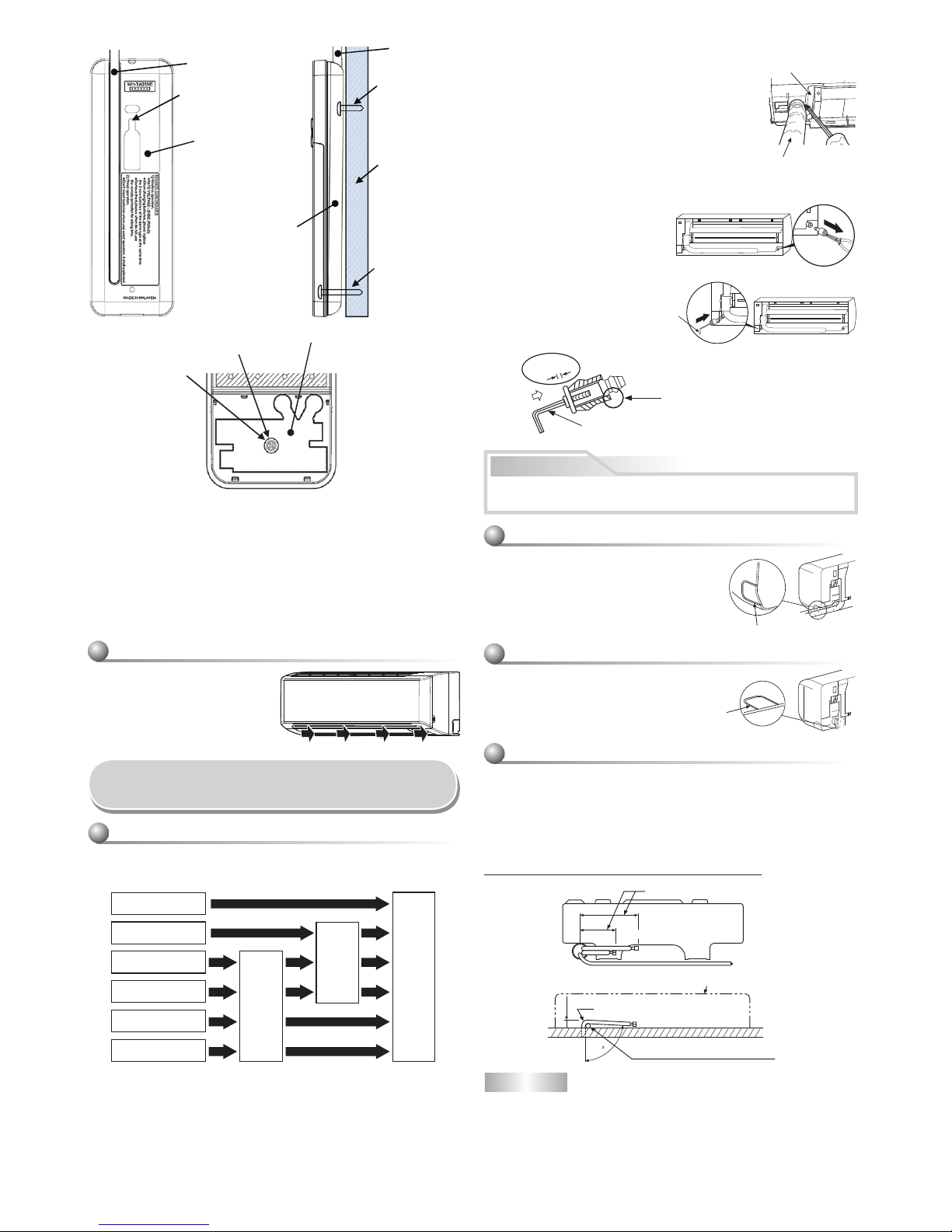
6
HINWEIS
Wenn die Leitung nicht korrekt gebogen wird, kann das Innengerät nicht fest an
der Wand befestigt werden.
Nach dem die Leitungen durch die Leitungsöffnung geführt wurden, sind die
Anschlüsse zu verbinden; danach sind beide Leitungen zu Isolieren.
* Da Kondensation zu Störungen des Geräts führen können, unbedingt beide
Anschlussleitungen isolieren. (Als lsoliermaterial ist Polyethylen-Schaum zu
verwenden.)
Verlegung von Leitungen und Kondensatablauf
So installieren Sie das Lufteinlaßabdeckgitter
an der Inneneinheit
• Beim Anbau des LufteintrittSchutzgitters wird im umgekehrter
Reihenfolge wie beim Ausbau
vorgegangen.
Installation von Leitungen und
Kondensatschlauch
Hinten rechts
Hinten links
Unterseite links
Links
Unterseite rechts
Rechts
Ausschneiden des
Frontplattenschlitzes
Wechseln des
Kondensat-
schlauchs
Leitungsvorbereitung
Schlitz
Entfernen des Kondensatschlauchs
• Der Drainage-Schlauch kann durch Entfernen der
Schraube vom Drainage-Schlauch herausgenommen
werden.
• Seien Sie beim Entfernen des Drainage-Schlauchs
mit den scharfen Kanten der Stahlplatte vorsichtig.
Sie können sich an den Kanten verletzten.
• Setzen Sie den Drainage-Schlauch zur Montage
so fest ein, bis das Verbindungsstück mit dem
Wärmeisolator Kontakt hat. Befestigen Sie es mit der
Original-Schraube.
Ablaufschlauch
Hitzeschutz
1. Ausschneiden des Frontplattenschlitzes
Den Schlitz an der linken oder rechten Seite der Frontabdeckung für
Anschluss an der linken bzw. rechten Seite sowie den Schlitz an der linken
oder rechten Unterseite der Frontabdeckung für Anschluss an der linken
bzw. rechten Unterseite ausschneiden.
2. Wechseln des Kondensatschlauchs
Für Leitungsanschluss an der linken Seite, Unterseite links bzw. Rückseite
links müssen Kondensatschlauch und –kappe geändert werden.
Entfernen der Kondensatkappe
Die Kondensatkappe mit einer
Spitzzange lösen und herausziehen.
Anbringen der Kondensatkappe
1) Sechskant-Inbusschlüssel
(4 mm) in Öffnung einpassen.
2) Kondensatkappe bis zum
Anschlag einführen.
Kondensatschlauch und Ablasskappe ordnungsgemäß fi xieren, damit
keine Wasserleckage entsteht.
Bei Leitungsanschluss rechts oder links
• Nach dem Einschlitzen der Frontplatte mit
einem Messer oder Abreißstift eine Öffnung
mit einer Zange o. Ä. vorbereiten.
Bei Leitungsanschluss an Unterseite rechts
oder links
• Nach dem Einschlitzen der Frontplatte
mit einem Messer oder Abreißstift
eine Öffnung mit einer Zange o. Ä.
vorbereiten.
Nach links weisende Anschlußleitung
• Die Anschlußleitung so biegen, daß diese 43 mm von der Wandoberfl he
verlft. Wenn der Wand-Abstand der Anschlußleitung 43 mm übersteigt,
kann das Innenger nicht sicher an der Wand befestigt werden.
Beim Biegen der Anschlußleitung ein Federbiegeger verwenden, um ein
Zerquetschen der Leitung zu vermeiden.
Die Anschlußleitung mit einem Radius von weniger als 30 mm biegen.
Anschlußleitung nach dem Einbau des Geräts (Abbildung)
VORSICHT
80
520 mm
420 mm
43 mm
Flüssigkeitesseite
Gasseite
(An der Vorderkante des Bördelrands)
Außenseite des Innengeräts
R 30 mm (Verwenden Sie Polisin Polyethylenkern oder etwas Ähnliches
für gebogene Leitung.)
Den Griff eines Schraubendrehers
o.ä. verwenden.
4 mm
Vor dem Einführen der Ablasskappe
kein Schmiermittel (Kältemittelöl) auftragen.
Die Anwendung führt zum Verschleiß und zu
Leckagen am Abfl ussstopfen.
Inbusschlüssel
(4 mm) einführen.
Kein
Zwischenraum
Schlitz
Kontrolle Kabel
Loch zum Anbringen
der Fernbedienung
Fernbedienung
Kontrolle Kabel
Schraube
(Ø3,1×16L) zum
Aufhängen der
Fernbedienung
Wand
Schraube
(Ø3,1×25L) zur
Befestigung der
Abdeckung des
Batterien Fachs
Fernbedienung
"#
*Bemerkung : 1. Die Verwendung eines doppelt isolierten Bleikabels zum
Anschluss der Fernbedienung und der Klimaanlage wird
empfohlen.
2. Bei Kabelfunktion, entspricht 1 Fernbedienung pro 1
Inneneinheit.
3. Bei Kabelfunktion, wird die Fernbedienung zur
Anfangsstellung zurückkehren (VOREINSTELLUNG,
TIMER und UHR werden zur Anfangseinstellung
zurückkehren), wenn die Stromverbindung der
Klimaanlage abgestellt wird.
$
Batterien Deckel
Schraube
Ziehen Sie fest, aber nicht mehr
als 0,15 N·m (0,02 kgf·m)
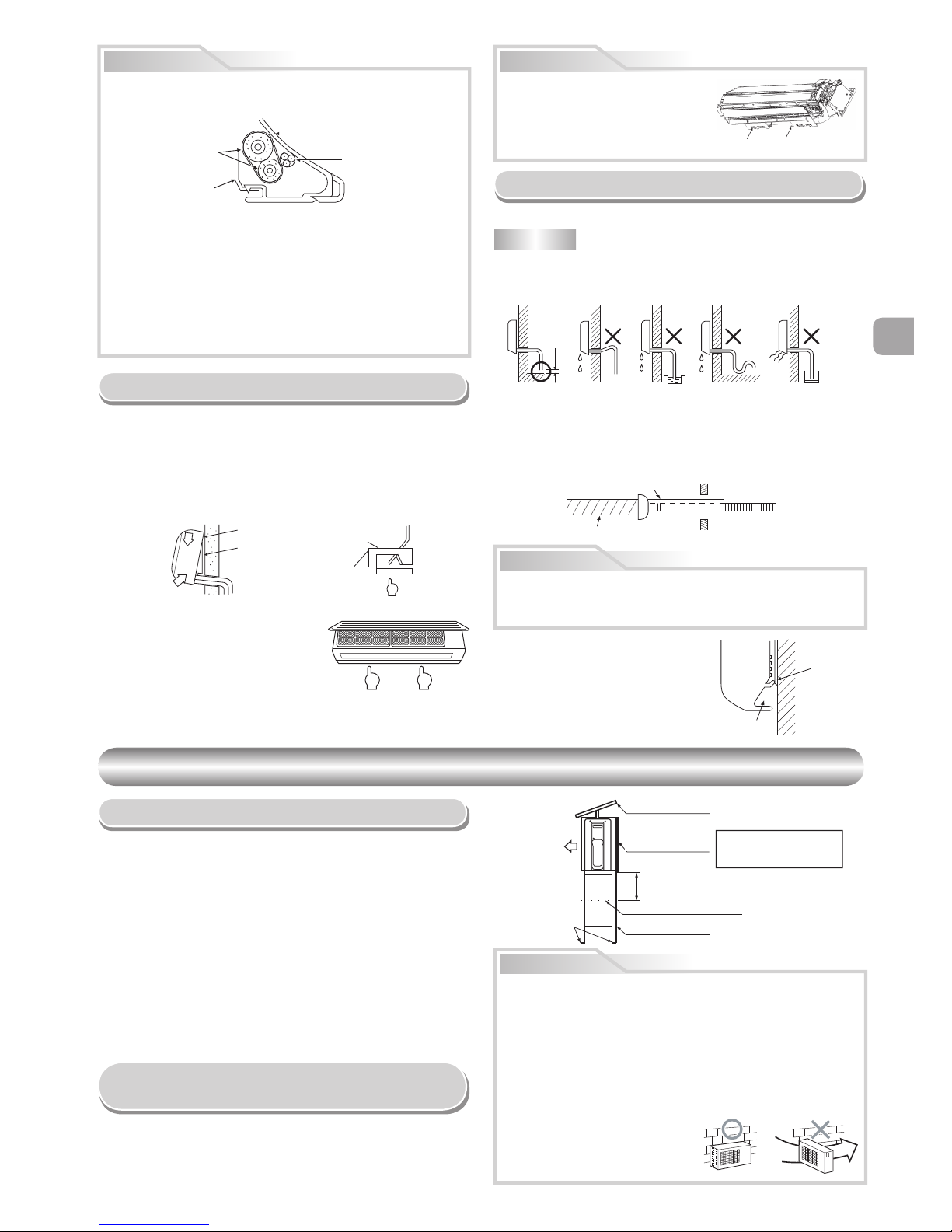
EN
ES
FR
DE
DE
PT
PL
CZ
RU
CR
HU
TR
NL
GR
SV
FI
NO
DK
RO
BG
EE
LV
SK
SI
7
• Verwenden sie für den Wasserabfl uss nicht den mitgelieferten Abfl ussnippel.
Lassen Sie das Wasser direkt aus den Abfl usslöchern abfl ießen.
• Bauen Sie einen Halterahmen und eine Schutzhaube über das Gerät, um das
Außenmodul vor Schneeansammlungen zu schützen.
* Verwenden sie keine doppelstöckige Anordnung
Vorsichtsmaßnahmen beim Einbau in Regionen
mit Schneefall und kalten Temperaturen
Hinweis
%
Schraube% Schraube
Wand
Ablaufführung
Für Leitungen
vorgesehener Bereich
Leitungshülle
Verlängerung des
Ablaufschlauchs
Innenseite des
Raums
Ablaufschlauch
Den Ablaufschlauch
nicht nach oben verlegen.
Den Ablaufschlauch
nicht wellenförmig biegen.
50 mm
oder mehr
Das Ende des
Ablaufschlauchs
nicht in Wasser einlegen.
Das ende des
ablaufschlauchs
nicht in einen
Abwasserkanal einlegen.
VORSICHT
Einbau des Innengeräts
• Um das Innengerät wieder von der
Montageplatte abzunehmen, das Gerät
zur Person ziehen, und gleichzeitig die
Unterseite an den bezeichneten Stellen
hochdrücken.
1. Die Leitungen durch die Öffnung in der Wand führen, dann das
Innengerät in die oberen Haken der Montageplatte einhängen.
2. Das Innengerät nach rechts und links drücken, um sich zu vergewissern,
daß das Gerät fest auf der Montageplatte aufgehängt ist.
3. Das Innengerät im unteren Bereich gegen die Wand drücken und den
unteren Teil des Gerät an der Montageplatte einhängen. Am unteren
Bereich des Innengeräts zur Person ziehen, um sich zu vergewissern,
daß das Gerät fest auf der Montageplatte aufsitzt.
Entwässerung
1. Den Ablaufschlauch nach unten weisend anbringen.
2. Die Ablaufwanne mit Wasser füllen und sich vergewissern, daß das Wasser
problemlos nach außen abläuft.
3.
Beim Anschließen der Ablaufschlauch-Verlängerung ist die Verbindungsstelle
der Ablaufschlauch-Verlängerung mit der Leitungshülle abzudecken.
HINWEIS
• Die Öffnung muß so angelegt werden, daß sie zur Außenseite hin schräg
nach unten weist.
Den Ablaufschlauch korrekt verlegen, um eine einwandfreie Entwässerung
zu gewährleisten.
Wenn das Wasser nicht einwandfrei abläuft, kann dies eine Beschädigung
von Gegenständen verursachen.
Dieses Klimagerät ist so konstruiert,
daß das an der Geräterückseite
anhaftende Kondenswasser in die
Ablaufwanne abgeleitet wird. Aus
diesem Grund dürfen Netzkabel und
andere Komponenten nicht an der
Ablaufführung verlegt werden.
VORSICHT
•
Die Zusatzleitungen (zwei) und das Verbindungskabel mit Isolierband fest
zusammenbinden. Bei nach links oder hinten links gerichteten Leitungen
sind nur die Zusatzleitungen (zwei) mit Isolierband zusammenzubinden.
Innengerät
Verbindungskabel
Zusatzleitungen
Montageplatte
• Die Leitungen so anordnen, daß keine der Leitungen aus der Rückplatte
des Innengeräts hervorsteht.
• Die Zusatzleitungen und Anschlußleitungen zusammenbinden, dann
das Isolierband an der Anschlußleitung abschneiden, um ein doppeltes
Umwicheln der Verbindungsstelle zu vermeiden; außerdem sind die
Anschlußstellen mit Vinylband o.ä. zu umwickeln.
• Da die Bildung von Kondensationswasser zu Funktionsstörung des
Geräts führen kann, müssen beide Anschlußleitungen isoliert werden.
(Als lsoliermaterial ist Polyethylen-Schaum zu verwenden.)
• Beim Biegen einer Leitung darauf achten, daß die Leitung nicht
beschädigt wird.
Der Unterteil des Innenmoduls könnte infolge
des Zustands der Rohrleitung schwimmen,
und sie können ihn nicht an der Einbauplatte
befestigen. Verwenden Sie in diesem Fall die
mitgelieferten
%
Schrauben für die Befestigung
des Moduls und der Einbauplatte.
AUSSENGERÄT
AUSSENGERÄT
Aufstellungsort
•
Einen Aufstellort wählen, der ausreichend Platz rund um das Außengerät bietet, wie in der
Zeichnung gezeigt
•
Das Gerät an einem Ort aufstellen, der das Gewicht des Geräts aufnehmen kann und an
dem das Betriebsgeräusch sowie die Vibrationen des Geräts nicht verstärkt werden
•
Einen Ort wählen, an dem das Geräusch bzw. die Auslaßluft nicht zu einer Belästigung der
Nachbarn führen könnte
•
Der Aufstellort sollte möglichst vor starker Windeinwirkung geschützt sein.
•
Am Aufstellort dürfen keine brennbaren Gase vorhanden sein
•
Das Gerät darf nicht so aufgestellt weden, daß es zu einer Durchgangsbehinderung führt
•
Wenn das Außengerät in einer erhöhten Position montiert werden soll, müssen die Füße
unbedingt gesichert werden.
•
Die zulässige Länge der Verbindungsleitung für 20 m.
•
Bei bis zu 15 m Länge der Verbindungsleitungen ist kein zusätzliches Kältemittel
erforderlich.
•
Bei Installationen mit einer Leitungslänge zwischen 16 und 20 m müssen Sie für jeden
zusätzlichen Meter Leitung 20 g Kältemittel hinzufügen.
•
Die zulässige Förderhöhe für 10 m.
•
Das Gerät an einem Ort aufstellen, an dem das Ablaufwasser keine Probleme verursacht
VORSICHT
1. Bauen Sie das Außenmodul an einem Platz ein, an dem weder Lufteintritt
noch –austritt beeinträchtigt sind.
2. Bei Montage des Außenmoduls an einer Stelle, die ständig starkem Wind
ausgesetzt ist, z.B. an einer Meeresküste oder an einem oberen Stockwerk
eines Gebäudes, ist die Funktion des Lüfters mit einem Windschutz oder
einer Ummantelung sicherzustellen.
3. Besonders in Gegenden mit starkem Wind muss dafür gesorgt werden, dass
kein Wind direkt ins Gerät bläst.
4. Der Einbau des Geräts an Plätzen der folgenden Art kann zu Schwierigkeiten
führen. Bauen Sie das Gerät nicht an solchen Stellen ein.
• Wo ständig Dämpfe von Maschinenöl auftreten.
• An Plätzen mit salzhaltiger Luft, etwa in Meeresnähe.
• An Plätzen, an denen die Luft
schwefl ige Gase enthält.
• An Plätzen, an denen hochfrequente
Schwingungen auftreten, etwa von
Audiogeräten, Schweißanlagen und
medizinischen Geräten.
Starker
wind
Ankerbolzen
Schneeschutz-Platte
Schneeschutz-Haube
Mindestens 50 cm oberhalb
der Schneeansammlungslinie
einbauen.
Mindestens 50 cm
Schneeansammlungs-Linie
Halterahmen
Vorderseite
1
2
1
Hier einhängen.
Montageplatte
Haken
Drücken
Drücken
Drücken
(Aushaken)
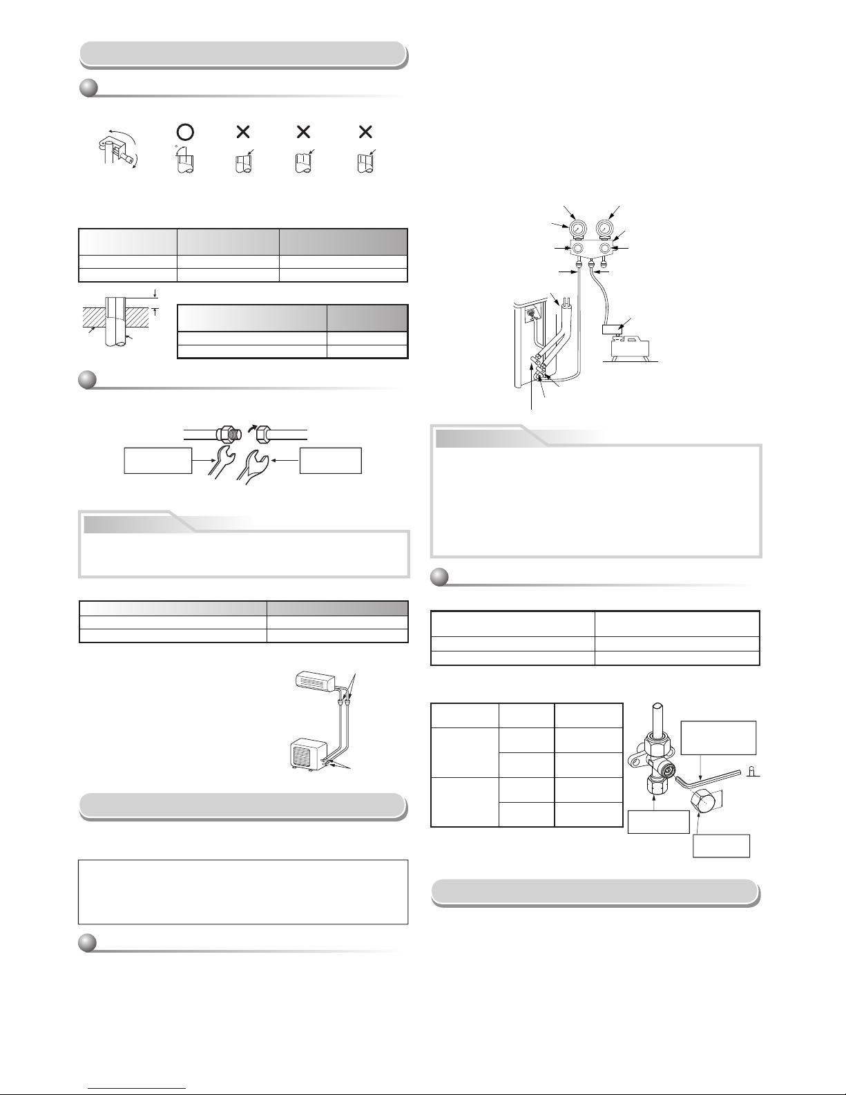
8
Imperial-Werkzeug (Typ Flügelmutter)
Außendurchmesser der
Kupferleitung
R410A
Ø6,35 mm 1,5 bis 2,0
Ø12,70 mm 2,0 bis 2,5
(Einheit : N•m)
Außendurchmesser der Kupferleitung Anzugsdrehmoment
Ø6,35 mm 14 bis 18 (1,4 bis 1,8 kgf·m)
Ø12,70 mm 50 bis 62 (5,0 bis 6,2 kgf·m)
ABSAUGEN
Saugen Sie mittels einer Vakuumpumpe die Luft aus dem Innenmodul
sowie aus den Verbindungsleitungen zwischen Innen- und Außenmodul
ab. Verwenden Sie im Außenmodul kein Kühlmittel. Näheres erfahren Sie
aus der Betriebsanleitung der Vakuumpumpe.
Außendurchmesser
der Kupferleitung
Bei Verwendung von
R410A-Werkzeug
Bei Verwendung von
herkömmlichem Werkzeug
Ø6,35 mm 0 bis 0,5 1,0 bis 1,5
Ø12,70 mm 0 bis 0,5 1,0 bis 1,5
• Drehmoment beim anziehen der Überwurfmuttern
Der Druck von R410A ist höher als der von
R22. (ca. 1,6-fach,) Deswegen müssen
die Überwurfmuttern der Leitungen
zwischen Innen- und Außenmodul mit
einem Drehmomentschlüssel mit dem
vorgeschriebenen Drehmoment angezogen
werden. Fehlerhafter Anschluss einer Leitung
kann zu Gasaustritt und zu Problemen im
Kühlsystem führen.
1.
Verbinden Sie den Füllschlauch vom Verteilerventil mit der Wartungsöffnung
des gasseitigen Kompaktventils.
2. Verbinden Sie den Füllschlauch mit der Öffnung der Vakuumpumpe.
3. Öffnen Sie den Niederdruckseitengriff des Meßverteilerventils vollständig.
4. Starten Sie die Vakuumpumpe, so daß die Entleerung beginnt. Führen Sie den
Entleerungsvorgang bei einer Leitungslänge von 20 m etwa 15 Minuten lang
durch. (d. h. 15 Minuten für 20 m bei einer Pumpkapazität von 27 l pro Minute)
Vergewissern Sie sich dann, daß der gesamte Druckmeßwert –101 kPa (–76
cmHg) beträgt.
5. Schließen Sie den Niederdruckseitengriff des Meßverteilerventils.
6.
Öffnen Sie den Ventilschaft der Service Ventile vollständig (gas- und
fl üssigkeitsseitig).
7. Lösen Sie den Füllschlauch von der Wartungsöffnung.
8. Befestigen Sie die Kappen auf den Service Ventile.
1. Entfernen Sie die Abdeckungen vom Ventil und den elektrischen Teilen
und der Kabelklemme am Außenmodul.
2. Die Leitungen des Kabels werden entsprechend den übereinstimmenden
Nummern am Klemmenblock des Innenbzw. Außenmoduls angeschlossen.
3. Führen Sie das Stromkabel und das Verbindungskabel voll in den
Klemmenblock und sichern Sie sie fest mit den Schrauben.
4. Isolieren Sie die nicht benötigten Adern sicher mit Isolierband aus Vinyl
oder einem anderen Material. Verlegen sie sie so, dass sie nicht mit
stromführenden oder sonstigen Metallteilen in Berührung kommen.
5. Sichern Sie Stromkabel und Verbindungskabel mit der Kabelklemme.
6. Bringen Sie die Abdeckungen des Anschlusskastens und des
Ventilkastens am Außenmodul an.
Verwenden Sie unbedingt eine Vakuumpumpe mit Rückfl ußschutz, so daß Öl
im Inneren der Pumpe nicht zurück in die Leitungen der Klimaanlage fl ießt,
sobald die Pumpe stoppt.
(Falls Öl aus der Vakuumpumpe in das mit R410A arbeitende Klimagerät
austritt, kann dies zu Problemen beim Kühlkreislauf führen.)
Verwendung der Vakuumpumpe
A
Leitung
Druck
platte
90
Abschrung Unebenheit Verzug
VORSICHT
Anschluß der Kühlmittelleitungen
1. Die Leitung mit einem Rohrschneider abschneiden.
2. Setzen Sie einen Doppelring in die Leitung ein, und weiten Sie die Leitung.
• Überstand beim Weiten : A (Einheit : mm)
Starr (Typ Kupplung)
Die anzuschließenden Leitungen zu den Anschlüssen ausrichten, dann die
Überwurfmuttern so weit wie möglich mit den Fingern festdrehen.
Festziehen der Verbindungsmutter
Darauf achten, daß die Mutter nicht zu fest angezogen wird. Bei zu
starkem Anziehen kann sich die Mutter unter gewissen Betriebsbedingungen spalten.
Bördeln
Entleeren
Sobald das Leitungen an der Innen- und Außeneinheit angeschlossen sind,
kann mit dem Evakuieren begonnen werden.
VORSICHT
Absperrventil am Flüssigkeitsseite
Wartungsöffnung (Ventil-kern (Einstellung Nadel))
Absperventil am Gasseite
Vakuum-
pumpe
Anpassungsvorrichtung von
Vakuumpumpe für Verhütung
gegenüberliegender
Strömung (Für R410A nur)
Zufuhrschlauch
(Für R410A nur)
Griff der Hochdruckseite (Bleiben
Sie vollständig geschlossen)
Verteilerventil
Druckmeßgerät
Verbindung Druckmeßgerät
Grift der Unterdruckseite
Zufuhrschlauch
(Für R410A nur)
Angeschlossenen Leitungen
–101 kPa
(–76 cmHg)
• 5 WICHTIGE HINWEISE ZU ARBEITEN AN DEN LEITUNGEN
(1) Staub und Verschmutzung sind restlos zu entfernen (Innenseite der
Anschlußleitungen).
(2)
Alle Verbindungen gut festziehen (zwischen Leitungen und dem Gerät).
(3) Die in den Leitungen enthaltenen Fremdgase und Luftfeuchtigkeit
sind mit einer Vakuumpumpe abzusaugen.
(4) Das Gerät auf Gasverlust überprüfen (an den Verbindungsstellen).
(5) Stellen Sie sicher, die Service Ventile vor dem Betrieb vollständig zu
öffnen.
Kabelanschlüsse
Überwurfmutter
Kontermutter
Seite mit
Außengewinde
Seite mit
Innengewinde
Zum Festziehen einen
Schraubenschlüssel verwenden.
Zum Festziehen eine
Drehmomentschlüssel verwenden.
Weitung an
Inneneinheit
Weitung an
Außeneinheit
Handhabung Hinweise zum Stopfbuchsenventil
• Öffnen Sie ganz das Ventilschaft, aber nicht weiter als dem Stöpsel.
• Schrauben Sie die Ventilkappe fest, mit einem Drehmoment laut folgender
Tabelle:
Rohrgröße des
Stopfbuchsenventils
Größe des Sechskantschlüssels
12,70 mm und kleiner A = 4 mm
15,88 mm A = 5 mm
Kappe
Kappengröße
(H)
Drehmoment
VentilstangenKappe
H17 - H19
14~18 N·m
(1,4 bis 1,8 kgf·m)
H22 - H30
33~42 N·m
(3,3 bis 4,2 kgf·m)
ArbeitsanschlussKappe
H14
8~12 N·m
(0,8 bis 1,2 kgf·m)
H17
14~18 N·m
(1,4 bis 1,8 kgf·m)
A
H
ArbeitsanschlussKappe
VentilstangenKappe
Es wird ein
Sechskantschlüssel
benötigt.
 Loading...