

Page 1

SERVICE MANUAL
FILE NO. SVM-15036-2
AIR-CONDITIONER
RAS-5M34S3AV-E
RAS-5M34S3AV-A
RAS-5M34S3AV-TR
SPLIT TYPE
R410A
July
, 201
5
Page 2

CONTENTS
FILE NO. SVM-15036
- 2 -
1. SAFETY PRECAUTIONS ............................................................ 3
2. SPECIFICATIONS ........................................................................ 5
3. REFRIGERANT R410A ............................................................. 26
4. CONSTRUCTION VIEWS .......................................................... 34
5. WIRING DIAGRAM ....................................................................36
6. SPECIFICATIONS OF ELECTRICAL PARTS............................ 38
7. REFRIGERANT CYCLE DIAGRAM........................................... 39
8. CONTROL BLOCK DIAGRAM .................................................. 46
9. OPERATION DESCRIPTION ..................................................... 48
10. INSTALLATION PROCEDURE ..................................................74
11. HOW TO DIAGNOSE THE TROUBLE ........................................ 93
12. HOW TO REPLACE THE MAIN PARTS ................................... 121
13.
EXPLODED VIEWS AND PARTS LIST.................................... 107
Page 3
1. SAFETY PRECAUTIONS
FILE NO. SVM-15036
- 3 -
The important contents concerned to the safety are described on the product itself and on this Service Manual.
Please read this Service Manual after understanding the described items thoroughly in the following contents
(Indications/Illustrated marks), and keep them.
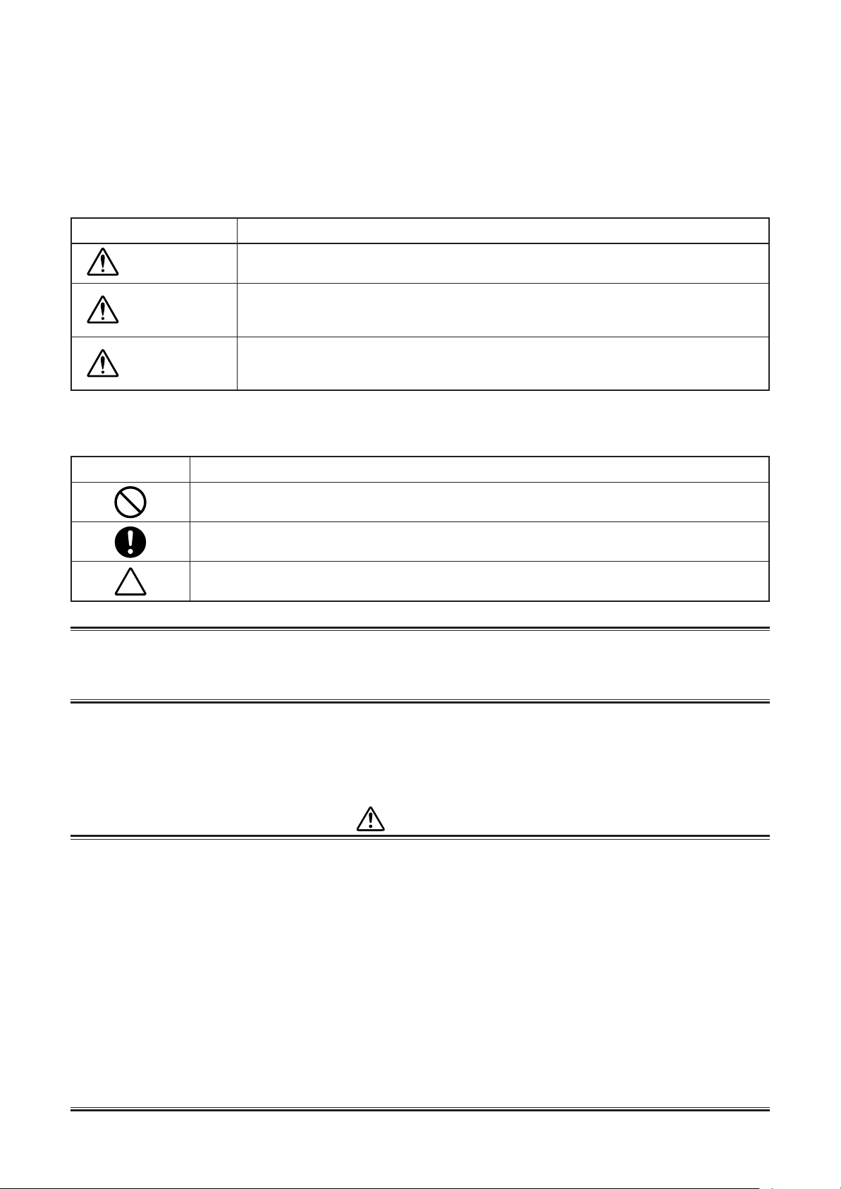
[Explanation of indications]
Indication
DANGER
WARNING
CAUTION
∗ Property damage : Enlarged damage concerned to property, furniture, and domestic animal/pet
Indicates contents assumed that an imminent danger causing a death or serious injury of
the repair engineers and the third parties when an incorrect work has been executed.
Indicates possibilities assumed that a danger causing a death or serious injury of the
repair engineers, the third parties, and the users due to troubles of the product after work
when an incorrect work has been executed.
Indicates contents assumed that an injury or property damage (∗) may be caused on the
repair engineers, the third parties, and the users due to troubles of the product after work
when an incorrect work has been executed.
Explanation
[Explanation of illustrated marks]
Mark Explanation
Indicates prohibited items (Forbidden items to do)
The sentences near an illustrated mark describe the concrete prohibited contents.
Indicates mandatory items (Compulsory items to do)
The sentences near an illustrated mark describe the concrete mandatory contents.
Indicates cautions (including danger/warning)
The sentences or illustration near or in an illustrated mark describe the concrete cautious contents.
For general public use
Power supply cord of outdoor unit shall be more than 2.5 mm² (H07RN-F or 60245IEC66) polychloroprene
sheathed flexible cord.
• Read this “SAFETY PRECAUTIONS” carefully before servicing.
• The precautions described below include the important items regarding safety. Observe them without fail.
• After the servicing work, perform a trial operation to check for any problem.
• Turn off the main power supply switch (or breaker) before the unit maintenance.
CAUTION
New Refrigerant Air Conditioner Installation
• THIS AIR CONDITIONER ADOPTS THE NEW HFC REFRIGERANT (R410A) WHICH DOES NOT
DESTROY OZONE LAYER.
R410A refrigerant is apt to be affected by impurities such as water, oxidizing membrane, and oils because
the working pressure of R410A refrigerant is approx. 1.6 times of refrigerant R22. Accompanied with the
adoption of the new refrigerant, the refrigeration machine oil has also been changed. Therefore, during
installation work, be sure that water, dust, former refrigerant, or refrigeration machine oil does not enter into
the new type refrigerant R410A air conditioner circuit.
To prevent mixing of refrigerant or refrigerating machine oil, the sizes of connecting sections of charging port
on main unit and installation tools are different from those used for the conventional refrigerant units.
Accordingly, special tools are required for the new refrigerant (R410A) units. For connecting pipes, use new
and clean piping materials with high pressure fittings made for R410A only, so that water and/or dust does
not enter. Moreover, do not use the existing piping because there are some problems with pressure fittings
and possible impurities in existing piping.
Page 4
CAUTION
FILE NO. SVM-15036
- 4 -
TO DISCONNECT THE APPLIANCE FROM THE MAIN POWER SUPPLY
A switch or circuit breaker that can disconnect all poles must be included in the fixed wiring.
Be sure to use an approved circuit breaker or switch.
DANGER
• The manufacturer shall not assume any liability for the damage caused by not observing the
description of this manual.
• Ask an authorized dealer or qualified installation professional to install/maintain the air conditioner.
INAPPROPRIATE SERVICING MAY RESULT IN WATER LEAKAGE, ELECTRIC SHOCK OR FIRE.
• TURN OFF MAIN POWER SUPPLY BEFORE ATTEMPTING ANY ELECTRICAL WORK.
MAKE SURE ALL POWER SWITCHES ARE OFF. FAILURE TO DO SO MAY CAUSE ELECTRIC SHOCK.
DANGER: HIGH VOLTAGE
The high voltage circuit is incorporated. Be careful to do the check service, as the electric shock may be
caused in case of touching parts on the P.C. board by hand.
• CORRECTLY CONNECT THE CONNECTING CABLE. IF THE CONNECTING CABLE IS INCORRECTLY CONNECTED, ELECTRIC PARTS MAY BE DAMAGED.
• CHECK THAT THE EARTH WIRE IS NOT BROKEN OR DISCONNECTED BEFORE SERVICE AND INSTALLATION. FAILURE TO DO SO MAY CAUSE ELECTRIC SHOCK.
• DO NOT INSTALL NEAR CONCENTRATIONS OF COMBUSTIBLE GAS OR GAS VAPORS. FAILURE TO FOLLOW THIS INSTRUCTION CAN RESULT IN FIRE OR EXPLOSION.
• TO PREVENT THE INDOOR UNIT FROM OVERHEATING AND CAUSING A FIRE HAZARD, PLACE THE UNIT
WELL AWAY (MORE THAN 2 M) FROM HEAT SOURCES SUCH AS RADIATORS, HEAT RESISTORS, FURNACE, STOVES, ETC.
• WHEN MOVING THE AIR-CONDITIONER FOR INSTALLATION IN ANOTHER PLACE, BE VERY CAREFUL NOT
TO ALLOW THE SPECIFIED REFRIGERANT (R410A) TO BECOME MIXED WITH ANY OTHER GASEOUS
BODY INTO THE REFRIGERATION CIRCUIT. IF AIR OR ANY OTHER GAS IS MIXED IN THE REFRIGERANT,
THE GAS PRESSURE IN THE REFRIGERATION CIRCUIT WILL BECOME ABNORMALLY HIGH AND IT MAY
RESULT IN THE PIPE BURSTING AND POSSIBLE PERSONNEL INJURIES.
• IN THE EVENT THAT THE REFRIGERANT GAS LEAKS OUT OF THE PIPE DURING THE SERVICE WORK AND
THE INSTALLATION WORK, IMMEDIATELY LET FRESH AIR INTO THE ROOM. IF THE REFRIGERANT GAS IS
HEATED, SUCH AS BY FIRE, GENERATION OF POISONOUS GAS MAY RESULT.
WARNING
• Do not use any refrigerant different from the one specified for complement or replacement.
Otherwise, abnormally high pressure may be generated in the refrigeration cycle, which may result in a failure or
explosion of the product or an injury to your body.
• Never modify this unit by removing any of the safety guards or bypass any of the safety interlock switches.
• Do not install in a place which cannot bear the weight of the unit.
Personal injury and property damage can result if the unit falls.
• After the installation work, confirm that refrigerant gas does not leak.
If refrigerant gas leaks into the room and flows near a fire source such as a cooking range, noxious gas may generate.
• The electrical work must be performed by a qualified electrician in accordance with the Installation
Manual. Make sure the air conditioner uses an exclusive circuit.
An insufficient circuit capacity or inappropriate installation may cause fire.
• When wiring, use the specified cables and connect the terminals securely to prevent external forces
applied to the cable from affecting the terminals.
• Be sure to provide grounding.
Do not connect ground wires to gas pipes, water pipes, lightning rods or ground wires for telephone cables.
• Conform to the regulations of the local electric company when wiring the power supply.
Inappropriate grounding may cause electric shock.
Page 5
CAUTION
FILE NO. SVM-15036
- 5 -
• Exposure of unit to water or other moisture before installation may result in an electrical short.
Do not store in a wet basement or expose to rain or water.
• Do not install in a place that can increase the vibration of the unit. Do not install in a place that can amplify
the noise level of the unit or where noise or discharged air might disturb neighbors.
• To avoid personal injury, be careful when handling parts with sharp edges.
• Perform the specified installation work to guard against an earthquake.
If the air conditioner is not installed appropriately, accidents may occur due to the falling unit.
2. SPECIFICATIONS
The indoor and outdoor units that can be used in combination are shown in the tables below.
Table of models that can be used in combination
Type Outdoor unit Combinations of indoor unit models that can be connected
Heat pump
NOTES
A 1-room connection is not an option for the indoor units (you cannot connect only one indoor unit).
Be sure to connect indoor units in two or more.
RAS-5M34S3AV-E, -A, -TR
Refer to page 8 to 25
2-1. Specifications
<Heat Pump Models>
RAS-5M34S3AV-E, -A, -TR
Unit model
Cooling Capacity (kW)
Cooling Capacity range (kW)
Heating Capacity (kW)
Heating Capacity range (kW)
Power supply
Electric
characteristics
COP
Operating noise
Outdoor unit Motor output (W)
Piping connection D unit liquid side/gas side
Wiring connection
Usable temperature range
Accessory
Outdoor RAS-
Operation mode
Total
(Cooling/Heating)
Outdoor
Full indoor units operating
(Cooling/Heating)
Dimension Width (mm)
Net weight (kg)
Compressor Type
Fan motor output (W)
Air flow rate (m³/h)
Type
Outdoor unit B unit liquid side/gas side
Maximum length (per unit) (m)
Maximum length (total) (m)
Maximum chargeless length (m)
Maximum height difference (m)
Name of refirigerant
Weight (kg)
Power supply / interconnection
Outdoor (Cooling/Heating) (°C)
Outdoor unit
Unit model RAS-
Installation manual
Running current (A)
Power consumption (W)
Power factor (%)
Starting current (A)
Height (mm)
Depth (mm)
Model
A unit liquid side/gas side
C unit liquid side/gas side
E unit liquid side/gas side
RAS-
220-240V 1Ph 50Hz / 220V 1Ph 60Hz
Cooling Heating
14.26 / 13.65 / 13.07
2980
95 95
Twin rotary type with DC-inverter variable speed control
3 Wires : includes earth / 4 Wires : includes earth
• For performance when each indoor unit is combined with other unit, refer to the separate table.
• The specifications may be subject to change without notice for purpose of improvement.
B13N3KV2-E1 (X5)
5M34S3AV-E, -A, -TR
10.0
3.7 to 11.0
12.0
2.7 to 14.0
13.56 / 12.97 / 12.43
14.26 / 13.65 / 13.07
3.36 / 4.24
5
2 / 55
890
900
320
78
2200
DA270A2T-20LD
High: 3666, Medium: 2800
100
Flare connection
Ø6.35 / Ø12.7
Ø6.35 / Ø12.7
Ø6.35 / Ø9.52
Ø6.35 / Ø9.52
Ø6.35 / Ø9.52
25
80
40
15
R410A
2.99
-10 to 46 / -15 to 24
5M34S3AV-E, -A, -TR
1
2833
Page 6
2-2-1. SUMMARIES OF PRODUCT CHARACTERISTICS
FILE NO. SVM-15036
- 6 -
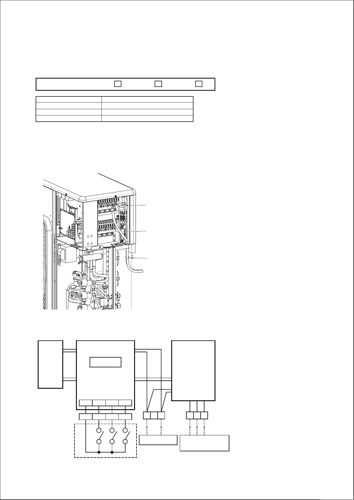
RAS-5M34S3AV-A
TKHVHDLUFRQGLWLRQHUVDUHFRPPRGLWLHVIRU'5(''HPDQG5HVSRQVH(QDEOLQJ'HYLFHWKDWFRPSOLHVZLWK
AS/NZS 4755.3.1.
These models supports DRM1 DRM2 DRM3.
AS/NZS 4755 DRM1
Demand response mode
DRM1
DRM2
DRM3
DRM2 DRM3
Description
Compressor off
E30m ≤ R × 0.50 × 0.5
E30m ≤ R × 0.75 × 0.5
*1: E30m = total electrical energy (kWh) used by the air conditioner for all purposes (including compressors,
controls and fans) over a 30 min period.
*2: R = rated input electrical power of the air conditioner (kW) at rated capacity in the mode in which it is
operating during the demand response event (i.e.cooling or heating).
DRED installation position
Cord clamp
DRED terminal block connections
Outline of DRED wiring
Demand response interface
CN101
Transformer
MCC-1653
CN102
COM DRM1 DRM2 DRM3
COM DRM1 DRM2 DRM3
CN100
CN105
Banding band
Outdoor control
NL
P.C. board
123
DRED
Locally procured
Power supply
Indoor (A~E) unit
Connecting
Page 7
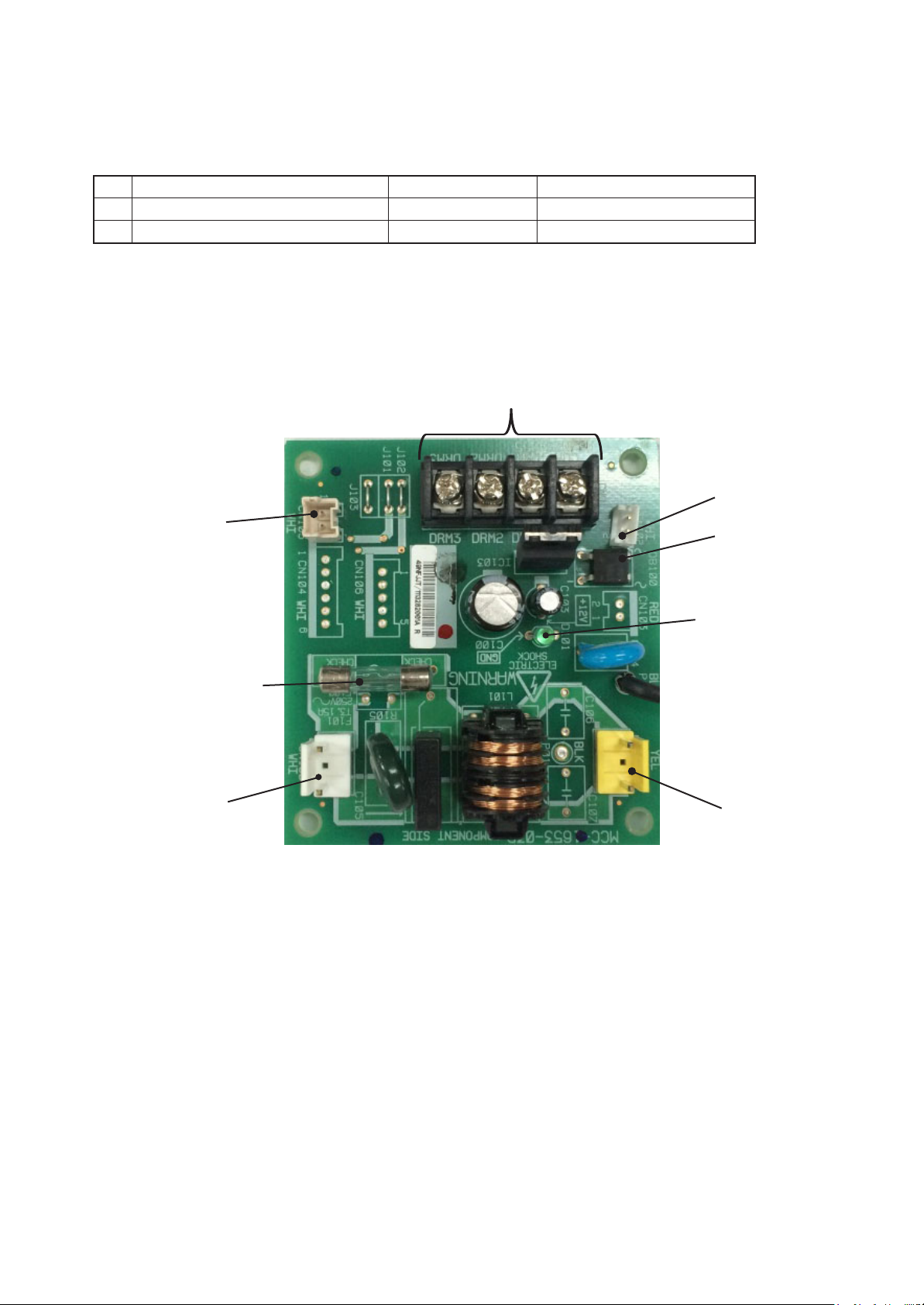
2-2-2. SPECIFICATIONS OF ELECTRICAL PARTS
FILE NO. SVM-15036
- 7 -
1. Parts for demand response (Common usage)
No. Parts name Type Specifications
1 Demand response P.C. board MCC-1653
2 Transformer TT-02
.
2
Demand response P.C. board
DRC signal reception connector CN01
AC230-240V,50Hz
AC230V,50/60Hz,150mA
DRC signal
transmission
connector
CN105
Power supply
protection fuse
F100 (250V/3.15A)
Power supply input
connector CN100
Transformer output
connector CN102
DB100
LED indicator D101
Transformer input
connector CN101
Page 8
Outdoor Unit : RAS-5M34S3AV-E,-A,-TR
FILE NO. SVM-15036
- 8 -
<Cooling / 220V>
Power supply
(V)
220
Operating
Status
1 unit
2 units
3 units
Indoor unit
ABCDE
07————
10————
13————
16————
18————
22————
24————
07 07 — — —
10 07 — — —
13 07 — — —
16 07 — — —
18 07 — — —
22 07 — — —
24 07 — — —
10 10 — — —
13 10 — — —
16 10 — — —
18 10 — — —
22 10 — — —
24 10 — — —
13 13 — — —
16 13 — — —
18 13 — — —
22 13 — — —
24 13 — — —
16 16 — — —
18 16 — — —
22 16 — — —
24 16 — — —
18 18 — — —
22 18 — — —
24 18 — — —
22 22 — — —
22 24 — — —
24 24 — — —
07 07 07 — —
10 07 07 — —
13 07 07 — —
16 07 07 — —
18 07 07 — —
22 07 07 — —
24 07 07 — —
10 10 07 — —
13 10 07 — —
16 10 07 — —
18 10 07 — —
22 10 07 — —
24 10 07 — —
13 13 07 — —
16 13 07 — —
18 13 07 — —
22 13 07 — —
24 13 07 — —
16 16 07 — —
18 16 07 — —
22 16 07 — —
24 16 07 — —
18 18 07 — —
22 18 07 — —
24 18 07 — —
10 10 10 — —
13 10 10 — —
16 10 10 — —
18 10 10 — —
22 10 10 — —
24 10 10 — —
13 13 10 — —
16 13 10 — —
18 13 10 — —
22 13 10 — —
24 13 10 — —
16 16 10 — —
18 16 10 — —
22 16 10 — —
24 16 10 — —
18 18 10 — —
13 13 13 — —
16 13 13 — —
18 13 13 — —
22 13 13 — —
24 13 13 — —
16 16 13 — —
16 16 16 — —
18 16 13 — —
22 16 13 — —
24 16 13 — —
18 18 13 — —
22 18 10 — —
22 18 13 — —
24 18 10 — —
24 18 13 — —
22 22 07 — —
22 22 10 — —
24 22 07 — —
24 22 10 — —
24 24 07 — —
24 24 10 — —
Unit Capacity
ABCDE
2.0————
2.7————
3.7————
4.5————
5.0————
6.0————
7.1————
2.00 2.00 — — —
2.70 2.00 — — —
3.70 2.00 — — —
4.08 1.82 — — —
4.50 1.80 — — —
4.73 1.58 — — —
5.31 1.49 — — —
2.70 2.70 — — —
3.41 2.49 — — —
3.94 2.36 — — —
4.09 2.21 — — —
4.69 2.11 — — —
5.22 1.98 — — —
3.15 3.15 — — —
3.73 3.07 — — —
3.91 2.89 — — —
4.45 2.75 — — —
4.73 2.47 — — —
3.60 3.60 — — —
3.79 3.41 — — —
4.17 3.13 — — —
4.47 2.83 — — —
3.60 3.60 — — —
4.04 3.36 — — —
4.34 3.06 — — —
4.00 4.00 — — —
3.66 4.34 — — —
4.05 4.05 — — —
2.00 2.00 2.00 — —
2.70 2.00 2.00 — —
3.65 1.97 1.97 — —
4.08 1.81 1.81 — —
4.28 1.71 1.71 — —
4.68 1.56 1.56 — —
4.99 1.41 1.41 — —
2.70 2.70 2.00 — —
3.39 2.48 1.83 — —
3.77 2.26 1.67 — —
3.97 2.14 1.59 — —
4.37 1.97 1.46 — —
4.69 1.78 1.32 — —
3.03 3.03 1.64 — —
3.44 2.83 1.53 — —
3.64 2.70 1.46 — —
4.00 2.47 1.33 — —
4.38 2.28 1.23 — —
3.19 3.19 1.42 — —
3.39 3.05 1.36 — —
3.79 2.84 1.26 — —
4.12 2.61 1.16 — —
3.29 3.29 1.32 — —
3.65 3.04 1.22 — —
3.98 2.80 1.12 — —
2.53 2.53 2.53 — —
3.13 2.28 2.28 — —
3.50 2.10 2.10 — —
3.70 2.00 2.00 — —
4.16 1.87 1.87 — —
4.49 1.71 1.71 — —
2.82 2.82 2.06 — —
3.22 2.65 1.93 — —
3.42 2.53 1.85 — —
3.82 2.36 1.72 — —
4.15 2.17 1.58 — —
3.04 3.04 1.82 — —
3.20 2.88 1.73 — —
3.64 2.73 1.64 — —
3.97 2.52 1.51 — —
3.11 3.11 1.68 — —
2.60 2.60 2.60 — —
2.99 2.46 2.46 — —
3.19 2.36 2.36 — —
3.58 2.21 2.21 — —
3.92 2.04 2.04 — —
2.80 2.80 2.30 — —
2.67 2.67 2.67 — —
2.99 2.69 2.21 — —
3.38 2.54 2.08 — —
3.71 2.35 1.93 — —
2.88 2.88 2.13 — —
3.50 2.92 1.58 — —
3.31 2.76 2.04 — —
3.89 2.74 1.48 — —
3.64 2.56 1.90 — —
3.43 3.43 1.14 — —
3.31 3.31 1.49 — —
3.81 3.22 1.07 — —
3.68 3.11 1.40 — —
3.59 3.59 1.01 — —
3.44 3.44 1.31 — —
Cooling capacity Power consumption Operating current
(kW) (W) (A)
2.0 (1.4–2.5) 650 (640– 700) 3.84 (3.83– 3.74)
2.7 (1.4–3.2) 750 (640– 950) 4.43 (3.83– 4.64)
3.7 (1.4–4.4) 1200 (640–1520) 6.20 (3.68– 7.20)
4.5 (1.4–5.0) 1650 (640–2000) 7.98 (3.68– 9.28)
5.0 (1.4–5.2) 1950 (640–2100) 9.33 (3.68– 9.74)
6.0 (2.4–6.8) 2020 (640–2500) 9.56 (3.68–11.60)
7.1 (2.4–7.2) 2390 (660–2960) 11.32 (3.80–13.73)
4.0 (2.5–5.0) 1520 (640–1770) 7.27 (3.64– 8.21)
4.7 (2.5–5.7) 1530 (640–1910) 7.32 (3.64– 8.86)
5.7 (2.6–6.5) 1810 (660–2130) 8.66 (3.75– 9.88)
5.9 (2.7–6.6) 1810 (660–2220) 8.66 (3.75–10.30)
6.3 (2.9–6.9) 2040 (670–2400) 9.76 (3.81–11.13)
6.3 (2.9–6.9) 2040 (670–2400) 9.76 (3.81–11.13)
6.8 (3.0–7.2) 2320 (690–2570) 11.10 (3.92–11.92)
5.4 (2.5–6.3) 1530 (640–2040) 7.32 (3.64– 9.46)
5.9 (2.7–6.6) 1810 (660–2220) 8.66 (3.75–10.30)
6.3 (2.9–6.9) 2040 (670–2400) 9.76 (3.81–11.13)
6.3 (2.9–6.9) 2040 (670–2400) 9.76 (3.81–11.13)
6.8 (3.0–7.2) 2320 (690–2570) 11.10 (3.92–11.92)
7.2 (3.2–7.5) 2550 (700–2750) 12.20 (3.98–12.76)
6.3 (2.9–6.9) 2040 (670–2400) 9.76 (3.81–11.13)
6.8 (3.0–7.2) 2320 (690–2570) 11.10 (3.92–11.92)
6.8 (3.0–7.2) 2320 (690–2570) 11.10 (3.92–11.92)
7.2 (3.2–7.5) 2550 (700–2750) 12.20 (3.98–12.76)
7.2 (3.2–7.5) 2550 (700–2750) 12.20 (3.98–12.76)
7.2 (3.2–7.5) 2550 (700–2750) 12.20 (3.98–12.76)
7.2 (3.2–7.5) 2550 (700–2750) 12.20 (3.98–12.76)
7.3 (3.2–7.5) 2550 (700–2750) 12.20 (3.98–12.76)
7.3 (3.2–7.5) 2550 (700–2750) 12.20 (3.98–12.76)
7.2 (3.2–7.5) 2550 (700–2750) 12.20 (3.98–12.76)
7.4 (3.2–7.5) 2550 (700–2750) 12.20 (3.98–12.76)
7.4 (3.2–7.5) 2550 (700–2750) 12.20 (3.98–12.76)
8.0 (3.2–8.3) 2170 (700–2370) 10.27 (3.98–10.99)
8.0 (3.2–8.3) 2170 (700–2370) 10.27 (3.98–10.99)
8.1 (3.2–8.4) 2200 (700–2400) 10.42 (3.98–11.13)
6.0 (3.8–7.5) 2400 (950–2720) 11.48 (4.80–12.62)
6.7 (3.8–8.2) 2400 (950–2720) 11.48 (4.80–12.62)
7.6 (3.9–8.3) 2410 (960–2740) 11.53 (4.85–12.71)
7.7 (4.0–8.5) 2410 (960–2790) 11.53 (4.85–12.94)
7.7 (4.0–8.5) 2410 (960–2790) 11.53 (4.85–12.94)
7.8 (4.1–8.6) 2430 (970–2810) 11.63 (4.90–13.03)
7.8 (4.1–8.6) 2430 (970–2810) 11.63 (4.90–13.03)
7.4 (3.8–8.2) 2400 (950–2720) 11.48 (4.80–12.62)
7.7 (3.9–8.3) 2410 (960–2740) 11.53 (4.85–12.71)
7.7 (4.0–8.5) 2410 (960–2790) 11.53 (4.85–12.94)
7.7 (4.0–8.5) 2410 (960–2790) 11.53 (4.85–12.94)
7.8 (4.1–8.6) 2430 (970–2810) 11.63 (4.90–13.03)
7.8 (4.1–8.6) 2430 (970–2810) 11.63 (4.90–13.03)
7.7 (4.0–8.5) 2410 (960–2790) 11.53 (4.85–12.94)
7.8 (4.1–8.6) 2430 (970–2810) 11.63 (4.90–13.03)
7.8 (4.1–8.6) 2430 (970–2810) 11.63 (4.90–13.03)
7.8 (4.1–8.6) 2430 (970–2810) 11.63 (4.90–13.03)
7.9 (4.1–8.7) 2440 (970–2830) 11.67 (4.90–13.13)
7.8 (4.1–8.6) 2430 (970–2810) 11.63 (4.90–13.03)
7.8 (4.1–8.6) 2430 (970–2810) 11.63 (4.90–13.03)
7.9 (4.1–8.7) 2440 (970–2830) 11.67 (4.90–13.13)
7.9 (4.1–8.7) 2440 (970–2830) 11.67 (4.90–13.13)
7.9 (4.1–8.7) 2440 (970–2830) 11.67 (4.90–13.13)
7.9 (4.1–8.7) 2440 (970–2830) 11.67 (4.90–13.13)
7.9 (4.1–8.7) 2440 (970–2830) 11.67 (4.90–13.13)
7.6 (3.8–8.2) 2400 (950–2720) 11.48 (4.80–12.62)
7.7 (3.9–8.3) 2410 (960–2740) 11.53 (4.85–12.71)
7.7 (4.0–8.5) 2410 (960–2790) 11.53 (4.85–12.94)
7.7 (4.0–8.5) 2410 (960–2790) 11.53 (4.85–12.94)
7.9 (4.1–8.7) 2440 (970–2830) 11.67 (4.90–13.13)
7.9 (4.1–8.7) 2440 (970–2830) 11.67 (4.90–13.13)
7.7 (4.0–8.5) 2410 (960–2790) 11.53 (4.85–12.94)
7.8 (4.1–8.6) 2430 (970–2810) 11.63 (4.90–13.03)
7.8 (4.1–8.6) 2430 (970–2810) 11.63 (4.90–13.03)
7.9 (4.1–8.7) 2440 (970–2830) 11.67 (4.90–13.13)
7.9 (4.1–8.7) 2440 (970–2830) 11.67 (4.90–13.13)
7.9 (4.1–8.7) 2440 (970–2830) 11.67 (4.90–13.13)
7.8 (4.1–8.6) 2430 (970–2810) 11.63 (4.90–13.03)
8.0 (4.3–9.0) 2450 (980–2900) 11.72 (4.95–13.45)
8.0 (4.3–9.0) 2450 (980–2900) 11.72 (4.95–13.45)
7.9 (4.1–8.7) 2440 (970–2830) 11.67 (4.90–13.13)
7.8 (4.1–8.6) 2430 (970–2810) 11.63 (4.90–13.03)
7.9 (4.1–8.7) 2440 (970–2830) 11.67 (4.90–13.13)
7.9 (4.1–8.7) 2440 (970–2830) 11.67 (4.90–13.13)
8.0 (4.3–9.0) 2450 (980–2900) 11.72 (4.95–13.45)
8.0 (4.3–9.0) 2450 (980–2900) 11.72 (4.95–13.45)
7.9 (4.1–8.7) 2440 (970–2830) 11.67 (4.90–13.13)
8.0 (4.3–9.0) 2450 (980–2900) 11.72 (4.95–13.45)
7.9 (4.1–8.7) 2440 (970–2830) 11.67 (4.90–13.13)
8.0 (4.3–9.0) 2450 (980–2900) 11.72 (4.95–13.45)
8.0 (4.3–9.0) 2450 (980–2900) 11.72 (4.95–13.45)
7.9 (4.1–8.7) 2440 (970–2830) 11.67 (4.90–13.13)
8.0 (4.1–9.0) 2015 (970–2500) 9.64 (4.90–11.60)
8.1 (4.1–9.0) 2040 (970–2500) 9.76 (4.90–11.60)
8.1 (4.1–9.0) 2040 (970–2500) 9.76 (4.90–11.60)
8.1 (4.1–9.0) 2040 (970–2500) 9.76 (4.90–11.60)
8.0 (4.1–8.8) 2015 (970–2405) 9.64 (4.90–11.15)
8.1 (4.1–8.9) 2040 (970–2430) 9.76 (4.90–11.27)
8.1 (4.1–8.9) 2040 (970–2430) 9.76 (4.90–11.27)
8.2 (4.1–9.0) 2065 (970–2455) 9.88 (4.90–11.39)
8.2 (4.1–9.0) 2065 (970–2455) 9.88 (4.90–11.39)
8.2 (4.1–9.0) 2065 (970–2455) 9.88 (4.90–11.39)
Total
Outdoor noise (dB)
Sound Sound
Pressure Power
66
52
66
52
66
52
66
52
66
52
66
52
66
52
66
52
66
52
66
52
66
52
66
52
66
52
66
52
66
52
66
52
66
52
66
52
66
52
66
52
66
52
66
52
66
52
66
52
66
52
66
52
66
52
66
52
66
52
66
52
66
52
66
52
66
52
66
52
66
52
66
52
66
52
66
52
66
52
66
52
66
52
66
52
66
52
66
52
66
52
66
52
66
52
66
52
66
52
66
52
66
52
66
52
66
52
66
52
66
52
66
52
66
52
66
52
66
52
66
52
66
52
66
52
66
52
66
52
66
52
66
52
66
52
66
52
66
52
66
52
66
52
66
52
66
52
66
52
66
52
66
52
66
52
66
52
66
52
66
52
66
52
66
52
66
52
66
52
66
52
66
52
66
52
66
52
66
52
66
52
66
52
66
52
66
52
66
52
66
52
66
52
66
52
• The above specification values are those under the conditions that the indoor DB/WB=27/19°C and the outdoor DB/WB=35/–°C.
Page 9
<Cooling / 220V> (Continued)
FILE NO. SVM-15036
- 9 -
Power supply
(V)
220
Operating
Status
4 units
Indoor unit
ABCDE
07 07 07 07 —
10 07 07 07 —
13 07 07 07 —
16 07 07 07 —
18 07 07 07 —
22 07 07 07 —
24 07 07 07 —
10 10 07 07 —
13 10 07 07 —
16 10 07 07 —
18 10 07 07 —
22 10 07 07 —
24 10 07 07 —
13 13 07 07 —
16 13 07 07 —
18 13 07 07 —
22 13 07 07 —
24 13 07 07 —
16 16 07 07 —
18 16 07 07 —
22 16 07 07 —
24 16 07 07 —
18 18 07 07 —
22 18 07 07 —
24 18 07 07 —
10 10 10 07 —
13 10 10 07 —
16 10 10 07 —
18 10 10 07 —
22 10 10 07 —
24 10 10 07 —
13 13 10 07 —
16 13 10 07 —
18 13 10 07 —
22 13 10 07 —
24 13 10 07 —
16 16 10 07 —
18 16 10 07 —
22 16 10 07 —
24 16 10 07 —
18 18 10 07 —
22 18 10 07 —
24 18 10 07 —
13 13 13 07 —
16 13 13 07 —
18 13 13 07 —
22 13 13 07 —
24 13 13 07 —
16 16 13 07 —
18 16 13 07 —
22 16 13 07 —
24 16 13 07 —
18 18 13 07 —
22 18 13 07 —
24 18 13 07 —
10 10 10 10 —
13 10 10 10 —
16 10 10 10 —
18 10 10 10 —
22 10 10 10 —
24 10 10 10 —
13 13 10 10 —
16 13 10 10 —
22 13 10 10 —
24 13 10 10 —
16 16 10 10 —
18 13 10 10 —
22 16 10 10 —
24 16 10 10 —
18 16 10 10 —
18 18 10 10 —
22 18 10 10 —
24 18 10 10 —
13 13 13 10 —
16 13 13 10 —
22 13 13 10 —
24 13 13 10 —
16 16 13 10 —
22 16 13 10 —
24 16 13 10 —
18 13 13 10 —
18 16 13 10 —
18 18 13 10 —
22 18 13 10 —
24 18 13 10 —
13 13 13 13 —
16 13 13 13 —
18 13 13 13 —
22 13 13 13 —
24 13 13 13 —
16 16 13 13 —
18 16 13 13 —
22 16 13 13 —
24 16 13 13 —
18 18 13 13 —
22 18 13 13 —
24 18 13 13 —
Unit Capacity
ABCDE
2.00 2.00 2.00 2.00 —
2.61 1.93 1.93 1.93 —
3.28 1.77 1.77 1.77 —
3.73 1.66 1.66 1.66 —
4.00 1.60 1.60 1.60 —
4.45 1.48 1.48 1.48 —
4.88 1.37 1.37 1.37 —
2.44 2.44 1.81 1.81 —
3.10 2.26 1.67 1.67 —
3.54 2.12 1.57 1.57 —
3.80 2.05 1.52 1.52 —
4.25 1.91 1.42 1.42 —
4.63 1.76 1.30 1.30 —
2.89 2.89 1.56 1.56 —
3.32 2.73 1.48 1.48 —
3.54 2.62 1.42 1.42 —
3.94 2.43 1.31 1.31 —
4.32 2.25 1.22 1.22 —
3.12 3.12 1.38 1.38 —
3.33 3.00 1.33 1.33 —
3.72 2.79 1.24 1.24 —
4.10 2.60 1.15 1.15 —
3.21 3.21 1.29 1.29 —
3.60 3.00 1.20 1.20 —
3.97 2.80 1.12 1.12 —
2.30 2.30 2.30 1.70 —
2.93 2.14 2.14 1.59 —
3.37 2.02 2.02 1.50 —
3.63 1.96 1.96 1.45 —
4.03 1.81 1.81 1.34 —
4.41 1.68 1.68 1.24 —
2.75 2.75 2.01 1.49 —
3.14 2.58 1.88 1.40 —
3.36 2.49 1.81 1.34 —
3.75 2.31 1.69 1.25 —
4.12 2.15 1.57 1.16 —
2.96 2.96 1.77 1.31 —
3.17 2.85 1.71 1.27 —
3.55 2.66 1.60 1.18 —
3.92 2.48 1.49 1.10 —
3.06 3.06 1.65 1.22 —
3.44 2.87 1.55 1.15 —
3.80 2.68 1.45 1.07 —
2.54 2.54 2.54 1.37 —
2.91 2.40 2.40 1.29 —
3.13 2.31 2.31 1.25 —
3.51 2.16 2.16 1.17 —
3.87 2.02 2.02 1.09 —
2.76 2.76 2.27 1.22 —
2.96 2.66 2.19 1.18 —
3.33 2.50 2.06 1.11 —
3.69 2.34 1.92 1.04 —
2.87 2.87 2.12 1.15 —
3.23 2.69 1.99 1.08 —
3.59 2.53 1.87 1.01 —
2.18 2.18 2.18 2.18 —
2.79 2.04 2.04 2.04 —
3.21 1.93 1.93 1.93 —
3.44 1.85 1.85 1.85 —
3.83 1.72 1.72 1.72 —
4.20 1.60 1.60 1.60 —
2.60 2.60 1.90 1.90 —
2.98 2.45 1.79 1.79 —
3.58 2.21 1.61 1.61 —
3.94 2.06 1.50 1.50 —
2.81 2.81 1.69 1.69 —
3.19 2.36 1.72 1.72 —
3.40 2.55 1.53 1.53 —
3.76 2.38 1.43 1.43 —
3.02 2.72 1.63 1.63 —
2.92 2.92 1.58 1.58 —
3.29 2.74 1.48 1.48 —
3.65 2.57 1.39 1.39 —
2.41 2.41 2.41 1.76 —
2.77 2.28 2.28 1.66 —
3.35 2.07 2.07 1.51 —
3.72 1.94 1.94 1.41 —
2.63 2.63 2.16 1.58 —
3.20 2.40 1.97 1.44 —
3.55 2.25 1.85 1.35 —
2.98 2.21 2.21 1.61 —
2.83 2.55 2.09 1.53 —
2.74 2.74 2.03 1.48 —
3.10 2.59 1.91 1.40 —
3.45 2.43 1.80 1.31 —
2.25 2.25 2.25 2.25 —
2.60 2.13 2.13 2.13 —
2.80 2.07 2.07 2.07 —
3.16 1.95 1.95 1.95 —
3.51 1.83 1.83 1.83 —
2.47 2.47 2.03 2.03 —
2.66 2.40 1.97 1.97 —
3.02 2.26 1.86 1.86 —
3.36 2.13 1.75 1.75 —
2.59 2.59 1.91 1.91 —
2.93 2.45 1.81 1.81 —
3.28 2.31 1.71 1.71 —
Cooling capacity Power consumption Operating current
(kW) (W) (A)
8.0 (4.0–8.7) 2550 (930–2800) 12.20 (4.70–12.99)
8.4 (4.0–8.8) 2710 (930–2820) 12.97 (4.70–13.08)
8.6 (4.1–9.0) 2720 (940–2850) 13.01 (4.75–13.22)
8.7 (4.1–9.1) 2720 (940–2850) 13.01 (4.75–13.22)
8.8 (4.1–9.2) 2730 (940–2880) 13.06 (4.75–13.36)
8.9 (4.1–9.3) 2730 (940–2880) 13.06 (4.75–13.36)
9.0 (4.2–9.4) 2740 (950–2900) 13.11 (4.80–13.45)
8.5 (4.0–8.9) 2710 (930–2820) 12.97 (4.70–13.08)
8.7 (4.1–9.1) 2720 (940–2850) 13.01 (4.75–13.22)
8.8 (4.1–9.2) 2730 (940–2880) 13.06 (4.75–13.36)
8.9 (4.1–9.3) 2730 (940–2880) 13.06 (4.75–13.36)
9.0 (4.2–9.4) 2740 (950–2900) 13.11 (4.80–13.45)
9.0 (4.2–9.4) 2740 (950–2900) 13.11 (4.80–13.45)
8.9 (4.1–9.3) 2730 (940–2880) 13.06 (4.75–13.36)
9.0 (4.2–9.4) 2740 (950–2900) 13.11 (4.80–13.45)
9.0 (4.2–9.4) 2740 (950–2900) 13.11 (4.80–13.45)
9.0 (4.2–9.4) 2740 (950–2900) 13.11 (4.80–13.45)
9.0 (4.2–9.4) 2740 (950–2900) 13.11 (4.80–13.45)
9.0 (4.2–9.4) 2740 (950–2900) 13.11 (4.80–13.45)
9.0 (4.2–9.4) 2740 (950–2900) 13.11 (4.80–13.45)
9.0 (4.2–9.4) 2740 (950–2900) 13.11 (4.80–13.45)
9.0 (4.2–9.4) 2740 (950–2900) 13.11 (4.80–13.45)
9.0 (4.2–9.4) 2740 (950–2900) 13.11 (4.80–13.45)
9.0 (4.2–9.4) 2740 (950–2900) 13.11 (4.80–13.45)
9.0 (4.2–9.4) 2740 (950–2900) 13.11 (4.80–13.45)
8.6 (4.1–9.0) 2720 (940–2850) 13.01 (4.75–13.22)
8.8 (4.1–9.2) 2730 (940–2880) 13.06 (4.75–13.36)
8.9 (4.1–9.3) 2730 (940–2880) 13.06 (4.75–13.36)
9.0 (4.2–9.4) 2740 (950–2900) 13.11 (4.80–13.45)
9.0 (4.2–9.4) 2740 (950–2900) 13.11 (4.80–13.45)
9.0 (4.2–9.4) 2740 (950–2900) 13.11 (4.80–13.45)
9.0 (4.2–9.4) 2740 (950–2900) 13.11 (4.80–13.45)
9.0 (4.2–9.4) 2740 (950–2900) 13.11 (4.80–13.45)
9.0 (4.2–9.4) 2740 (950–2900) 13.11 (4.80–13.45)
9.0 (4.2–9.4) 2740 (950–2900) 13.11 (4.80–13.45)
9.0 (4.2–9.4) 2740 (950–2900) 13.11 (4.80–13.45)
9.0 (4.2–9.4) 2740 (950–2900) 13.11 (4.80–13.45)
9.0 (4.2–9.4) 2740 (950–2900) 13.11 (4.80–13.45)
9.0 (4.2–9.4) 2740 (950–2900) 13.11 (4.80–13.45)
9.0 (4.2–9.4) 2740 (950–2900) 13.11 (4.80–13.45)
9.0 (4.2–9.4) 2740 (950–2900) 13.11 (4.80–13.45)
9.0 (4.2–9.4) 2740 (950–2900) 13.11 (4.80–13.45)
9.0 (4.2–9.4) 2740 (950–2900) 13.11 (4.80–13.45)
9.0 (4.2–9.4) 2740 (950–2900) 13.11 (4.80–13.45)
9.0 (4.2–9.4) 2740 (950–2900) 13.11 (4.80–13.45)
9.0 (4.2–9.4) 2740 (950–2900) 13.11 (4.80–13.45)
9.0 (4.2–9.4) 2740 (950–2900) 13.11 (4.80–13.45)
9.0 (4.2–9.4) 2740 (950–2900) 13.11 (4.80–13.45)
9.0 (4.2–9.4) 2740 (950–2900) 13.11 (4.80–13.45)
9.0 (4.2–9.4) 2740 (950–2900) 13.11 (4.80–13.45)
9.0 (4.2–9.4) 2740 (950–2900) 13.11 (4.80–13.45)
9.0 (4.2–9.4) 2740 (950–2900) 13.11 (4.80–13.45)
9.0 (4.2–9.4) 2740 (950–2900) 13.11 (4.80–13.45)
9.0 (4.2–9.4) 2740 (950–2900) 13.11 (4.80–13.45)
9.0 (4.2–9.4) 2740 (950–2900) 13.11 (4.80–13.45)
8.7 (4.1–9.1) 2720 (940–2850) 13.01 (4.75–13.22)
8.9 (4.1–9.3) 2730 (940–2880) 13.06 (4.75–13.36)
9.0 (4.2–9.4) 2740 (950–2900) 13.11 (4.80–13.45)
9.0 (4.2–9.4) 2740 (950–2900) 13.11 (4.80–13.45)
9.0 (4.2–9.4) 2740 (950–2900) 13.11 (4.80–13.45)
9.0 (4.2–9.4) 2740 (950–2900) 13.11 (4.80–13.45)
9.0 (4.2–9.4) 2740 (950–2900) 13.11 (4.80–13.45)
9.0 (4.2–9.4) 2740 (950–2900) 13.11 (4.80–13.45)
9.0 (4.2–9.4) 2740 (950–2900) 13.11 (4.80–13.45)
9.0 (4.2–9.4) 2740 (950–2900) 13.11 (4.80–13.45)
9.0 (4.2–9.4) 2740 (950–2900) 13.11 (4.80–13.45)
9.0 (4.2–9.4) 2740 (950–2900) 13.11 (4.80–13.45)
9.0 (4.2–9.4) 2740 (950–2900) 13.11 (4.80–13.45)
9.0 (4.2–9.4) 2740 (950–2900) 13.11 (4.80–13.45)
9.0 (4.2–9.4) 2740 (950–2900) 13.11 (4.80–13.45)
9.0 (4.2–9.4) 2740 (950–2900) 13.11 (4.80–13.45)
9.0 (4.2–9.4) 2740 (950–2900) 13.11 (4.80–13.45)
9.0 (4.2–9.4) 2740 (950–2900) 13.11 (4.80–13.45)
9.0 (4.2–9.4) 2740 (950–2900) 13.11 (4.80–13.45)
9.0 (4.2–9.4) 2740 (950–2900) 13.11 (4.80–13.45)
9.0 (4.2–9.4) 2740 (950–2900) 13.11 (4.80–13.45)
9.0 (4.2–9.4) 2740 (950–2900) 13.11 (4.80–13.45)
9.0 (4.2–9.4) 2740 (950–2900) 13.11 (4.80–13.45)
9.0 (4.2–9.4) 2740 (950–2900) 13.11 (4.80–13.45)
9.0 (4.2–9.4) 2740 (950–2900) 13.11 (4.80–13.45)
9.0 (4.2–9.4) 2740 (950–2900) 13.11 (4.80–13.45)
9.0 (4.2–9.4) 2740 (950–2900) 13.11 (4.80–13.45)
9.0 (4.2–9.4) 2740 (950–2900) 13.11 (4.80–13.45)
9.0 (4.2–9.4) 2740 (950–2900) 13.11 (4.80–13.45)
9.0 (4.2–9.4) 2740 (950–2900) 13.11 (4.80–13.45)
9.0 (4.2–9.4) 2740 (950–2900) 13.11 (4.80–13.45)
9.0 (4.2–9.4) 2740 (950–2900) 13.11 (4.80–13.45)
9.0 (4.2–9.4) 2740 (950–2900) 13.11 (4.80–13.45)
9.0 (4.2–9.4) 2740 (950–2900) 13.11 (4.80–13.45)
9.0 (4.2–9.4) 2740 (950–2900) 13.11 (4.80–13.45)
9.0 (4.2–9.4) 2740 (950–2900) 13.11 (4.80–13.45)
9.0 (4.2–9.4) 2740 (950–2900) 13.11 (4.80–13.45)
9.0 (4.2–9.4) 2740 (950–2900) 13.11 (4.80–13.45)
9.0 (4.2–9.4) 2740 (950–2900) 13.11 (4.80–13.45)
9.0 (4.2–9.4) 2740 (950–2900) 13.11 (4.80–13.45)
9.0 (4.2–9.4) 2740 (950–2900) 13.11 (4.80–13.45)
9.0 (4.2–9.4) 2740 (950–2900) 13.11 (4.80–13.45)
Total
Outdoor noise (dB)
Sound Sound
Pressure Power
66
52
66
52
66
52
66
52
66
52
66
52
66
52
66
52
66
52
66
52
66
52
66
52
66
52
66
52
66
52
66
52
66
52
66
52
66
52
66
52
66
52
66
52
66
52
66
52
66
52
66
52
66
52
66
52
66
52
66
52
66
52
66
52
66
52
66
52
66
52
66
52
66
52
66
52
66
52
66
52
66
52
66
52
66
52
66
52
66
52
66
52
66
52
66
52
66
52
66
52
66
52
66
52
66
52
66
52
66
52
66
52
66
52
66
52
66
52
66
52
66
52
66
52
66
52
66
52
66
52
66
52
66
52
66
52
66
52
66
52
66
52
66
52
66
52
66
52
66
52
66
52
66
52
66
52
66
52
66
52
66
52
66
52
66
52
66
52
66
52
66
52
66
52
66
52
66
52
66
52
66
52
66
52
66
52
66
52
66
52
66
52
66
52
• The above specification values are those under the conditions that the indoor DB/WB=27/19°C and the outdoor DB/WB=35/–°C.
Page 10
<Cooling / 220V> (Continued)
FILE NO. SVM-15036
- 10 -
Power supply
(V)
220
Operating
Status
5 units
Indoor unit
ABCDE
07 07 07 07 07
10 07 07 07 07
13 07 07 07 07
16 07 07 07 07
18 07 07 07 07
10 10 07 07 07
13 10 07 07 07
16 10 07 07 07
18 10 07 07 07
13 13 07 07 07
16 13 07 07 07
18 13 07 07 07
16 16 07 07 07
18 16 07 07 07
10 10 10 07 07
13 10 10 07 07
13 13 10 07 07
16 10 10 07 07
18 10 10 07 07
13 13 13 07 07
16 13 13 07 07
18 13 13 07 07
16 16 10 07 07
18 16 10 07 07
16 16 13 07 07
18 16 13 07 07
10 10 10 10 07
13 10 10 10 07
16 10 10 10 07
18 10 10 10 07
13 13 10 10 07
16 13 10 10 07
18 13 10 10 07
16 16 10 10 07
13 13 13 10 07
16 13 13 10 07
16 16 13 10 07
13 13 13 13 07
16 13 13 13 07
16 16 13 13 07
10 10 10 10 10
13 10 10 10 10
16 10 10 10 10
18 10 10 10 10
13 13 10 10 10
16 13 10 10 10
18 13 10 10 10
16 16 10 10 10
13 13 13 10 10
16 13 13 10 10
18 13 13 10 10
16 16 13 10 10
13 13 13 13 10
16 13 13 13 10
18 13 13 13 10
16 16 13 13 10
13 13 13 13 13
16 13 13 13 13
22 07∗ 07∗ 07∗ 07∗
22 10∗ 07∗ 07∗ 07∗
22 10∗ 10∗ 07∗ 07∗
22 10∗ 10∗ 10∗ 07∗
22 10∗ 10∗ 10∗ 10∗
22 13∗ 07∗ 07∗ 07∗
22 13∗ 10∗ 07∗ 07∗
22 13∗ 10∗ 10∗ 07∗
22 13∗ 10∗ 10∗ 10∗
22 13∗ 13∗ 07∗ 07∗
22 13∗ 13∗ 10∗ 07∗
22 13∗ 13∗ 10∗ 10∗
22 13∗ 13∗ 13∗ 07∗
24 07∗ 07∗ 07∗ 07∗
24 10∗ 07∗ 07∗ 07∗
24 10∗ 10∗ 07∗ 07∗
24 10∗ 10∗ 10∗ 07∗
24 10∗ 10∗ 10∗ 10∗
24 13∗ 07∗ 07∗ 07∗
24 13∗ 10∗ 07∗ 07∗
24 13∗ 10∗ 10∗ 07∗
24 13∗ 10∗ 10∗ 10∗
24 13∗ 13∗ 07∗ 07∗
24 13∗ 13∗ 10∗ 07∗
Unit Capacity
ABCDE
1.96 1.96 1.96 1.96 1.96
2.50 1.85 1.85 1.85 1.85
3.13 1.69 1.69 1.69 1.69
3.56 1.58 1.58 1.58 1.58
3.81 1.52 1.52 1.52 1.52
2.34 2.34 1.74 1.74 1.74
2.95 2.16 1.60 1.60 1.60
3.38 2.03 1.50 1.50 1.50
3.61 1.95 1.45 1.45 1.45
2.73 2.73 1.48 1.48 1.48
3.14 2.58 1.39 1.39 1.39
3.37 2.49 1.35 1.35 1.35
2.97 2.97 1.32 1.32 1.32
3.19 2.87 1.28 1.28 1.28
2.21 2.21 2.21 1.64 1.64
2.80 2.04 2.04 1.51 1.51
2.60 2.60 1.90 1.40 1.40
3.21 1.92 1.92 1.42 1.42
3.44 1.86 1.86 1.38 1.38
2.43 2.43 2.43 1.31 1.31
2.80 2.30 2.30 1.25 1.25
3.02 2.23 2.23 1.21 1.21
2.84 2.84 1.70 1.26 1.26
3.06 2.75 1.65 1.22 1.22
2.67 2.67 2.19 1.19 1.19
2.88 2.59 2.13 1.15 1.15
2.09 2.09 2.09 2.09 1.55
2.65 1.94 1.94 1.94 1.43
3.05 1.83 1.83 1.83 1.36
3.28 1.77 1.77 1.77 1.31
2.48 2.48 1.81 1.81 1.34
2.86 2.35 1.71 1.71 1.27
3.07 2.28 1.66 1.66 1.23
2.72 2.72 1.63 1.63 1.21
2.32 2.32 2.32 1.69 1.25
2.68 2.21 2.21 1.61 1.19
2.56 2.56 2.11 1.54 1.14
2.18 2.18 2.18 2.18 1.18
2.53 2.08 2.08 2.08 1.13
2.42 2.42 1.99 1.99 1.08
1.98 1.98 1.98 1.98 1.98
2.53 1.84 1.84 1.84 1.84
2.91 1.75 1.75 1.75 1.75
3.13 1.69 1.69 1.69 1.69
2.36 2.36 1.72 1.72 1.72
2.73 2.25 1.64 1.64 1.64
2.95 2.18 1.59 1.59 1.59
2.61 2.61 1.56 1.56 1.56
2.22 2.22 2.22 1.62 1.62
2.58 2.12 2.12 1.55 1.55
2.78 2.06 2.06 1.50 1.50
2.49 2.49 2.04 1.49 1.49
2.09 2.09 2.09 2.09 1.53
2.46 2.02 2.02 2.02 1.48
2.66 1.97 1.97 1.97 1.44
2.36 2.36 1.94 1.94 1.41
2.00 2.00 2.00 2.00 2.00
2.33 1.92 1.92 1.92 1.92
4.24 1.41 1.41 1.41 1.41
4.04 1.82 1.35 1.35 1.35
3.86 1.74 1.74 1.29 1.29
3.69 1.66 1.66 1.66 1.23
3.54 1.59 1.59 1.59 1.59
3.78 2.33 1.26 1.26 1.26
3.62 2.23 1.63 1.21 1.21
3.47 2.14 1.56 1.56 1.16
3.37 2.08 1.52 1.52 1.52
3.41 2.11 2.11 1.14 1.14
3.31 2.04 2.04 1.49 1.10
3.19 1.97 1.97 1.44 1.44
3.14 1.94 1.94 1.94 1.05
4.65 1.31 1.31 1.31 1.31
4.45 1.69 1.25 1.25 1.25
4.26 1.62 1.62 1.20 1.20
4.09 1.55 1.55 1.55 1.15
3.93 1.49 1.49 1.49 1.49
4.18 2.18 1.18 1.18 1.18
4.02 2.09 1.53 1.13 1.13
3.86 2.01 1.47 1.47 1.09
3.76 1.96 1.43 1.43 1.43
3.80 1.98 1.98 1.07 1.07
3.70 1.93 1.93 1.41 1.04
Cooling capacity Power consumption Operating current
(kW) (W) (A)
9.8 (3.7–10.8)
9.9 (3.7–10.9)
9.9 (3.7–10.9)
9.9 (3.7–10.9)
9.9 (3.7–10.9)
9.9 (3.7–10.9)
9.9 (3.7–10.9)
9.9 (3.7–10.9)
9.9 (3.7–10.9)
9.9 (3.7–10.9)
9.9 (3.7–10.9)
9.9 (3.7–10.9)
9.9 (3.7–10.9)
9.9 (3.7–10.9)
9.9 (3.7–10.9)
9.9 (3.7–10.9)
9.9 (3.7–10.9)
9.9 (3.7–10.9)
9.9 (3.7–10.9)
9.9 (3.7–10.9)
9.9 (3.7–10.9)
9.9 (3.7–10.9)
9.9 (3.7–10.9)
9.9 (3.7–10.9)
9.9 (3.7–10.9)
9.9 (3.7–10.9)
9.9 (3.7–10.9)
9.9 (3.7–10.9)
9.9 (3.7–10.9)
9.9 (3.7–10.9)
9.9 (3.7–10.9)
9.9 (3.7–10.9)
9.9 (3.7–10.9)
9.9 (3.7–10.9)
9.9 (3.7–10.9)
9.9 (3.7–10.9)
9.9 (3.7–10.9)
9.9 (3.7–10.9)
9.9 (3.7–10.9)
9.9 (3.7–10.9)
9.9 (3.7–10.9)
9.9 (3.7–10.9)
9.9 (3.7–10.9)
9.9 (3.7–10.9)
9.9 (3.7–10.9)
9.9 (3.7–10.9)
9.9 (3.7–10.9)
9.9 (3.7–10.9)
9.9 (3.7–10.9)
9.9 (3.7–10.9)
9.9 (3.7–10.9)
10.0 (3.7–11.0)
9.9 (3.7–10.9)
10.0 (3.7–11.0)
10.0 (3.7–11.0)
10.0 (3.7–11.0)
10.0 (3.7–11.0)
10.0 (3.7–11.0)
9.9 (3.7–11.0) 2946 (950–3700) 14.10 (4.80–17.16)
9.9 (3.7–11.0) 2946 (950–3700) 14.10 (4.80–17.16)
9.9 (3.7–11.0) 2946 (950–3700) 14.10 (4.80–17.16)
9.9 (3.7–11.0) 2946 (950–3700) 14.10 (4.80–17.16)
9.9 (3.7–11.0) 2946 (950–3700) 14.10 (4.80–17.16)
9.9 (3.7–11.0) 2946 (950–3700) 14.10 (4.80–17.16)
9.9 (3.7–11.0) 2946 (950–3700) 14.10 (4.80–17.16)
9.9 (3.7–11.0) 2946 (950–3700) 14.10 (4.80–17.16)
10.0 (3.7–11.0)
9.9 (3.7–11.0) 2946 (950–3700) 14.10 (4.80–17.16)
10.0 (3.7–11.0)
10.0 (3.7–11.0)
10.0 (3.7–11.0)
9.9 (3.7–11.0) 2946 (950–3700) 14.10 (4.80–17.16)
9.9 (3.7–11.0) 2946 (950–3700) 14.10 (4.80–17.16)
9.9 (3.7–11.0) 2946 (950–3700) 14.10 (4.80–17.16)
9.9 (3.7–11.0) 2946 (950–3700) 14.10 (4.80–17.16)
9.9 (3.7–11.0) 2946 (950–3700) 14.10 (4.80–17.16)
9.9 (3.7–11.0) 2946 (950–3700) 14.10 (4.80–17.16)
9.9 (3.7–11.0) 2946 (950–3700) 14.10 (4.80–17.16)
9.9 (3.7–11.0) 2946 (950–3700) 14.10 (4.80–17.16)
10.0 (3.7–11.0)
9.9 (3.7–11.0) 2946 (950–3700) 14.10 (4.80–17.16)
10.0 (3.7–11.0)
Total
2917 (950–3630) 13.96 (4.80–16.84)
2946 (950–3670) 14.10 (4.80–17.02)
2946 (950–3670) 14.10 (4.80–17.02)
2946 (950–3670) 14.10 (4.80–17.02)
2946 (950–3670) 14.10 (4.80–17.02)
2946 (950–3670) 14.10 (4.80–17.02)
2946 (950–3670) 14.10 (4.80–17.02)
2946 (950–3670) 14.10 (4.80–17.02)
2946 (950–3670) 14.10 (4.80–17.02)
2946 (950–3670) 14.10 (4.80–17.02)
2946 (950–3670) 14.10 (4.80–17.02)
2946 (950–3670) 14.10 (4.80–17.02)
2946 (950–3670) 14.10 (4.80–17.02)
2946 (950–3670) 14.10 (4.80–17.02)
2946 (950–3670) 14.10 (4.80–17.02)
2946 (950–3670) 14.10 (4.80–17.02)
2946 (950–3670) 14.10 (4.80–17.02)
2946 (950–3670) 14.10 (4.80–17.02)
2946 (950–3670) 14.10 (4.80–17.02)
2946 (950–3670) 14.10 (4.80–17.02)
2946 (950–3670) 14.10 (4.80–17.02)
2946 (950–3670) 14.10 (4.80–17.02)
2946 (950–3670) 14.10 (4.80–17.02)
2946 (950–3670) 14.10 (4.80–17.02)
2946 (950–3670) 14.10 (4.80–17.02)
2946 (950–3670) 14.10 (4.80–17.02)
2946 (950–3670) 14.10 (4.80–17.02)
2946 (950–3670) 14.10 (4.80–17.02)
2946 (950–3670) 14.10 (4.80–17.02)
2946 (950–3670) 14.10 (4.80–17.02)
2946 (950–3670) 14.10 (4.80–17.02)
2946 (950–3670) 14.10 (4.80–17.02)
2946 (950–3670) 14.10 (4.80–17.02)
2946 (950–3670) 14.10 (4.80–17.02)
2946 (950–3670) 14.10 (4.80–17.02)
2946 (950–3670) 14.10 (4.80–17.02)
2946 (950–3670) 14.10 (4.80–17.02)
2946 (950–3670) 14.10 (4.80–17.02)
2946 (950–3670) 14.10 (4.80–17.02)
2946 (950–3670) 14.10 (4.80–17.02)
2946 (950–3670) 14.10 (4.80–17.02)
2946 (950–3670) 14.10 (4.80–17.02)
2946 (950–3670) 14.10 (4.80–17.02)
2946 (950–3670) 14.10 (4.80–17.02)
2946 (950–3670) 14.10 (4.80–17.02)
2946 (950–3670) 14.10 (4.80–17.02)
2946 (950–3670) 14.10 (4.80–17.02)
2946 (950–3670) 14.10 (4.80–17.02)
2946 (950–3670) 14.10 (4.80–17.02)
2946 (950–3670) 14.10 (4.80–17.02)
2946 (950–3670) 14.10 (4.80–17.02)
2980 (950–3700) 14.26 (4.80–17.16)
2946 (950–3670) 14.10 (4.80–17.02)
2980 (950–3700) 14.26 (4.80–17.16)
2980 (950–3700) 14.26 (4.80–17.16)
2980 (950–3700) 14.26 (4.80–17.16)
2980 (950–3700) 14.26 (4.80–17.16)
2980 (950–3700) 14.26 (4.80–17.16)
2980 (950–3700) 14.26 (4.80–17.16)
2980 (950–3700) 14.26 (4.80–17.16)
2980 (950–3700) 14.26 (4.80–17.16)
2980 (950–3700) 14.26 (4.80–17.16)
2980 (950–3700) 14.26 (4.80–17.16)
2980 (950–3700) 14.26 (4.80–17.16)
Outdoor noise (dB)
Sound Sound
Pressure Power
66
52
66
52
66
52
66
52
66
52
66
52
66
52
66
52
66
52
66
52
66
52
66
52
66
52
66
52
66
52
66
52
66
52
66
52
66
52
66
52
66
52
66
52
66
52
66
52
66
52
66
52
66
52
66
52
66
52
66
52
66
52
66
52
66
52
66
52
66
52
66
52
66
52
66
52
66
52
66
52
66
52
66
52
66
52
66
52
66
52
66
52
66
52
66
52
66
52
66
52
66
52
66
52
66
52
66
52
66
52
66
52
66
52
66
52
66
52
66
52
66
52
66
52
66
52
66
52
66
52
66
52
66
52
66
52
66
52
66
52
66
52
66
52
66
52
66
52
66
52
66
52
66
52
66
52
66
52
66
52
66
52
66
52
∗ Applicable FCU are "N3KV2" series and "N3KVP" series.
• The above specification values are those under the conditions that the indoor DB/WB=27/19°C and the outdoor DB/WB=35/–°C.
Page 11

<Cooling / 230V>
FILE NO. SVM-15036
- 11 -
Power supply
(V)
230
Operating
Status
1 unit
2 units
3 units
Indoor unit
ABCDE
07————
10————
13————
16————
18————
22————
24————
07 07 — — —
10 07 — — —
13 07 — — —
16 07 — — —
18 07 — — —
22 07 — — —
24 07 — — —
10 10 — — —
13 10 — — —
16 10 — — —
18 10 — — —
22 10 — — —
24 10 — — —
13 13 — — —
16 13 — — —
18 13 — — —
22 13 — — —
24 13 — — —
16 16 — — —
18 16 — — —
22 16 — — —
24 16 — — —
18 18 — — —
22 18 — — —
24 18 — — —
22 22 — — —
22 24 — — —
24 24 — — —
07 07 07 — —
10 07 07 — —
13 07 07 — —
16 07 07 — —
18 07 07 — —
22 07 07 — —
24 07 07 — —
10 10 07 — —
13 10 07 — —
16 10 07 — —
18 10 07 — —
22 10 07 — —
24 10 07 — —
13 13 07 — —
16 13 07 — —
18 13 07 — —
22 13 07 — —
24 13 07 — —
16 16 07 — —
18 16 07 — —
22 16 07 — —
24 16 07 — —
18 18 07 — —
22 18 07 — —
24 18 07 — —
10 10 10 — —
13 10 10 — —
16 10 10 — —
18 10 10 — —
22 10 10 — —
24 10 10 — —
13 13 10 — —
16 13 10 — —
18 13 10 — —
22 13 10 — —
24 13 10 — —
16 16 10 — —
18 16 10 — —
22 16 10 — —
24 16 10 — —
18 18 10 — —
13 13 13 — —
16 13 13 — —
18 13 13 — —
22 13 13 — —
24 13 13 — —
16 16 13 — —
16 16 16 — —
18 16 13 — —
22 16 13 — —
24 16 13 — —
18 18 13 — —
22 18 10 — —
22 18 13 — —
24 18 10 — —
24 18 13 — —
22 22 07 — —
22 22 10 — —
24 22 07 — —
24 22 10 — —
24 24 07 — —
24 24 10 — —
Unit Capacity
ABCDE
2.0 — — — —
2.7 — — — —
3.7 — — — —
4.5 — — — —
5.0 — — — —
6.0 — — — —
7.1 — — — —
2.00 2.00 — — —
2.70 2.00 — — —
3.70 2.00 — — —
4.08 1.82 — — —
4.50 1.80 — — —
4.73 1.58 — — —
5.31 1.49 — — —
2.70 2.70 — — —
3.41 2.49 — — —
3.94 2.36 — — —
4.09 2.21 — — —
4.69 2.11 — — —
5.22 1.98 — — —
3.15 3.15 — — —
3.73 3.07 — — —
3.91 2.89 — — —
4.45 2.75 — — —
4.73 2.47 — — —
3.60 3.60 — — —
3.79 3.41 — — —
4.17 3.13 — — —
4.47 2.83 — — —
3.60 3.60 — — —
4.04 3.36 — — —
4.34 3.06 — — —
4.00 4.00 — — —
3.66 4.34 — — —
4.05 4.05 — — —
2.00 2.00 2.00 — —
2.70 2.00 2.00 — —
3.65 1.97 1.97 — —
4.08 1.81 1.81 — —
4.28 1.71 1.71 — —
4.68 1.56 1.56 — —
4.99 1.41 1.41 — —
2.70 2.70 2.00 — —
3.39 2.48 1.83 — —
3.77 2.26 1.67 — —
3.97 2.14 1.59 — —
4.37 1.97 1.46 — —
4.69 1.78 1.32 — —
3.03 3.03 1.64 — —
3.44 2.83 1.53 — —
3.64 2.70 1.46 — —
4.00 2.47 1.33 — —
4.38 2.28 1.23 — —
3.19 3.19 1.42 — —
3.39 3.05 1.36 — —
3.79 2.84 1.26 — —
4.12 2.61 1.16 — —
3.29 3.29 1.32 — —
3.65 3.04 1.22 — —
3.98 2.80 1.12 — —
2.53 2.53 2.53 — —
3.13 2.28 2.28 — —
3.50 2.10 2.10 — —
3.70 2.00 2.00 — —
4.16 1.87 1.87 — —
4.49 1.71 1.71 — —
2.82 2.82 2.06 — —
3.22 2.65 1.93 — —
3.42 2.53 1.85 — —
3.82 2.36 1.72 — —
4.15 2.17 1.58 — —
3.04 3.04 1.82 — —
3.20 2.88 1.73 — —
3.64 2.73 1.64 — —
3.97 2.52 1.51 — —
3.11 3.11 1.68 — —
2.60 2.60 2.60 — —
2.99 2.46 2.46 — —
3.19 2.36 2.36 — —
3.58 2.21 2.21 — —
3.92 2.04 2.04 — —
2.80 2.80 2.30 — —
2.67 2.67 2.67 — —
2.99 2.69 2.21 — —
3.38 2.54 2.08 — —
3.71 2.35 1.93 — —
2.88 2.88 2.13 — —
3.50 2.92 1.58 — —
3.31 2.76 2.04 — —
3.89 2.74 1.48 — —
3.64 2.56 1.90 — —
3.43 3.43 1.14 — —
3.31 3.31 1.49 — —
3.81 3.22 1.07 — —
3.68 3.11 1.40 — —
3.59 3.59 1.01 — —
3.44 3.44 1.31 — —
Cooling capacity Power consumption Operating current
(kW) (W) (A)
2.0 (1.4–2.5) 650 (640– 700) 3.67 (3.66– 3.58)
2.7 (1.4–3.2) 750 (640– 950) 4.23 (3.66– 4.44)
3.7 (1.4–4.4) 1200 (640–1520) 5.93 (3.52– 6.88)
4.5 (1.4–5.0) 1650 (640–2000) 7.63 (3.52– 8.87)
5.0 (1.4–5.2) 1950 (640–2100) 8.92 (3.52– 9.32)
6.0 (2.4–6.8) 2020 (640–2500) 9.15 (3.52–11.09)
7.1 (2.4–7.2) 2390 (660–2960) 10.82 (3.63–13.13)
4.0 (2.5–5.0) 1520 (640–1770) 6.96 (3.48– 7.85)
4.7 (2.5–5.7) 1530 (640–1910) 7.00 (3.48– 8.47)
5.7 (2.6–6.5) 1810 (660–2130) 8.28 (3.59– 9.45)
5.9 (2.7–6.6) 1810 (660–2220) 8.28 (3.59– 9.85)
6.3 (2.9–6.9) 2040 (670–2400) 9.34 (3.64–10.65)
6.3 (2.9–6.9) 2040 (670–2400) 9.34 (3.64–10.65)
6.8 (3.0–7.2) 2320 (690–2570) 10.62 (3.75–11.40)
5.4 (2.5–6.3) 1530 (640–2040) 7.00 (3.48– 9.05)
5.9 (2.7–6.6) 1810 (660–2220) 8.28 (3.59– 9.85)
6.3 (2.9–6.9) 2040 (670–2400) 9.34 (3.64–10.65)
6.3 (2.9–6.9) 2040 (670–2400) 9.34 (3.64–10.65)
6.8 (3.0–7.2) 2320 (690–2570) 10.62 (3.75–11.40)
7.2 (3.2–7.5) 2550 (700–2750) 11.67 (3.80–12.20)
6.3 (2.9–6.9) 2040 (670–2400) 9.34 (3.64–10.65)
6.8 (3.0–7.2) 2320 (690–2570) 10.62 (3.75–11.40)
6.8 (3.0–7.2) 2320 (690–2570) 10.62 (3.75–11.40)
7.2 (3.2–7.5) 2550 (700–2750) 11.67 (3.80–12.20)
7.2 (3.2–7.5) 2550 (700–2750) 11.67 (3.80–12.20)
7.2 (3.2–7.5) 2550 (700–2750) 11.67 (3.80–12.20)
7.2 (3.2–7.5) 2550 (700–2750) 11.67 (3.80–12.20)
7.3 (3.2–7.5) 2550 (700–2750) 11.67 (3.80–12.20)
7.3 (3.2–7.5) 2550 (700–2750) 11.67 (3.80–12.20)
7.2 (3.2–7.5) 2550 (700–2750) 11.67 (3.80–12.20)
7.4 (3.2–7.5) 2550 (700–2750) 11.67 (3.80–12.20)
7.4 (3.2–7.5) 2550 (700–2750) 11.67 (3.80–12.20)
8.0 (3.2–8.3) 2170 (700–2370) 9.83 (3.80–10.51)
8.0 (3.2–8.3) 2170 (700–2370) 9.83 (3.80–10.51)
8.1 (3.2–8.4) 2200 (700–2400) 9.96 (3.80–10.65)
6.0 (3.8–7.5) 2400 (950–2720) 10.98 (4.59–12.07)
6.7 (3.8–8.2) 2400 (950–2720) 10.98 (4.59–12.07)
7.6 (3.9–8.3) 2410 (960–2740) 11.03 (4.64–12.16)
7.7 (4.0–8.5) 2410 (960–2790) 11.03 (4.64–12.38)
7.7 (4.0–8.5) 2410 (960–2790) 11.03 (4.64–12.38)
7.8 (4.1–8.6) 2430 (970–2810) 11.12 (4.69–12.47)
7.8 (4.1–8.6) 2430 (970–2810) 11.12 (4.69–12.47)
7.4 (3.8–8.2) 2400 (950–2720) 10.98 (4.59–12.07)
7.7 (3.9–8.3) 2410 (960–2740) 11.03 (4.64–12.16)
7.7 (4.0–8.5) 2410 (960–2790) 11.03 (4.64–12.38)
7.7 (4.0–8.5) 2410 (960–2790) 11.03 (4.64–12.38)
7.8 (4.1–8.6) 2430 (970–2810) 11.12 (4.69–12.47)
7.8 (4.1–8.6) 2430 (970–2810) 11.12 (4.69–12.47)
7.7 (4.0–8.5) 2410 (960–2790) 11.03 (4.64–12.38)
7.8 (4.1–8.6) 2430 (970–2810) 11.12 (4.69–12.47)
7.8 (4.1–8.6) 2430 (970–2810) 11.12 (4.69–12.47)
7.8 (4.1–8.6) 2430 (970–2810) 11.12 (4.69–12.47)
7.9 (4.1–8.7) 2440 (970–2830) 11.17 (4.69–12.56)
7.8 (4.1–8.6) 2430 (970–2810) 11.12 (4.69–12.47)
7.8 (4.1–8.6) 2430 (970–2810) 11.12 (4.69–12.47)
7.9 (4.1–8.7) 2440 (970–2830) 11.17 (4.69–12.56)
7.9 (4.1–8.7) 2440 (970–2830) 11.17 (4.69–12.56)
7.9 (4.1–8.7) 2440 (970–2830) 11.17 (4.69–12.56)
7.9 (4.1–8.7) 2440 (970–2830) 11.17 (4.69–12.56)
7.9 (4.1–8.7) 2440 (970–2830) 11.17 (4.69–12.56)
7.6 (3.8–8.2) 2400 (950–2720) 10.98 (4.59–12.07)
7.7 (3.9–8.3) 2410 (960–2740) 11.03 (4.64–12.16)
7.7 (4.0–8.5) 2410 (960–2790) 11.03 (4.64–12.38)
7.7 (4.0–8.5) 2410 (960–2790) 11.03 (4.64–12.38)
7.9 (4.1–8.7) 2440 (970–2830) 11.17 (4.69–12.56)
7.9 (4.1–8.7) 2440 (970–2830) 11.17 (4.69–12.56)
7.7 (4.0–8.5) 2410 (960–2790) 11.03 (4.64–12.38)
7.8 (4.1–8.6) 2430 (970–2810) 11.12 (4.69–12.47)
7.8 (4.1–8.6) 2430 (970–2810) 11.12 (4.69–12.47)
7.9 (4.1–8.7) 2440 (970–2830) 11.17 (4.69–12.56)
7.9 (4.1–8.7) 2440 (970–2830) 11.17 (4.69–12.56)
7.9 (4.1–8.7) 2440 (970–2830) 11.17 (4.69–12.56)
7.8 (4.1–8.6) 2430 (970–2810) 11.12 (4.69–12.47)
8.0 (4.3–9.0) 2450 (980–2900) 11.21 (4.73–12.87)
8.0 (4.3–9.0) 2450 (980–2900) 11.21 (4.73–12.87)
7.9 (4.1–8.7) 2440 (970–2830) 11.17 (4.69–12.56)
7.8 (4.1–8.6) 2430 (970–2810) 11.12 (4.69–12.47)
7.9 (4.1–8.7) 2440 (970–2830) 11.17 (4.69–12.56)
7.9 (4.1–8.7) 2440 (970–2830) 11.17 (4.69–12.56)
8.0 (4.3–9.0) 2450 (980–2900) 11.21 (4.73–12.87)
8.0 (4.3–9.0) 2450 (980–2900) 11.21 (4.73–12.87)
7.9 (4.1–8.7) 2440 (970–2830) 11.17 (4.69–12.56)
8.0 (4.3–9.0) 2450 (980–2900) 11.21 (4.73–12.87)
7.9 (4.1–8.7) 2440 (970–2830) 11.17 (4.69–12.56)
8.0 (4.3–9.0) 2450 (980–2900) 11.21 (4.73–12.87)
8.0 (4.3–9.0) 2450 (980–2900) 11.21 (4.73–12.87)
7.9 (4.1–8.7) 2440 (970–2830) 11.17 (4.69–12.56)
8.0 (4.1–9.0) 2015 (970–2500) 9.22 (4.69–11.09)
8.1 (4.1–9.0) 2040 (970–2500) 9.34 (4.69–11.09)
8.1 (4.1–9.0) 2040 (970–2500) 9.34 (4.69–11.09)
8.1 (4.1–9.0) 2040 (970–2500) 9.34 (4.69–11.09)
8.0 (4.1–8.8) 2015 (970–2405) 9.22 (4.69–10.67)
8.1 (4.1–8.9) 2040 (970–2430) 9.34 (4.69–10.78)
8.1 (4.1–8.9) 2040 (970–2430) 9.34 (4.69–10.78)
8.2 (4.1–9.0) 2065 (970–2455) 9.45 (4.69–10.89)
8.2 (4.1–9.0) 2065 (970–2455) 9.45 (4.69–10.89)
8.2 (4.1–9.0) 2065 (970–2455) 9.45 (4.69–10.89)
Total
Outdoor noise (dB)
Sound Sound
Pressure Power
66
52
66
52
66
52
66
52
66
52
66
52
66
52
66
52
66
52
66
52
66
52
66
52
66
52
66
52
66
52
66
52
66
52
66
52
66
52
66
52
66
52
66
52
66
52
66
52
66
52
66
52
66
52
66
52
66
52
66
52
66
52
66
52
66
52
66
52
66
52
66
52
66
52
66
52
66
52
66
52
66
52
66
52
66
52
66
52
66
52
66
52
66
52
66
52
66
52
66
52
66
52
66
52
66
52
66
52
66
52
66
52
66
52
66
52
66
52
66
52
66
52
66
52
66
52
66
52
66
52
66
52
66
52
66
52
66
52
66
52
66
52
66
52
66
52
66
52
66
52
66
52
66
52
66
52
66
52
66
52
66
52
66
52
66
52
66
52
66
52
66
52
66
52
66
52
66
52
66
52
66
52
66
52
66
52
66
52
66
52
66
52
66
52
• The above specification values are those under the conditions that the indoor DB/WB=27/19°C and the outdoor DB/WB=35/–°C.
Page 12

<Cooling / 230V> (Continued)
FILE NO. SVM-15036
- 12 -
Power supply
(V)
230
Operating
Status
4 units
Indoor unit
ABCDE
07 07 07 07 —
10 07 07 07 —
13 07 07 07 —
16 07 07 07 —
18 07 07 07 —
22 07 07 07 —
24 07 07 07 —
10 10 07 07 —
13 10 07 07 —
16 10 07 07 —
18 10 07 07 —
22 10 07 07 —
24 10 07 07 —
13 13 07 07 —
16 13 07 07 —
18 13 07 07 —
22 13 07 07 —
24 13 07 07 —
16 16 07 07 —
18 16 07 07 —
22 16 07 07 —
24 16 07 07 —
18 18 07 07 —
22 18 07 07 —
24 18 07 07 —
10 10 10 07 —
13 10 10 07 —
16 10 10 07 —
18 10 10 07 —
22 10 10 07 —
24 10 10 07 —
13 13 10 07 —
16 13 10 07 —
18 13 10 07 —
22 13 10 07 —
24 13 10 07 —
16 16 10 07 —
18 16 10 07 —
22 16 10 07 —
24 16 10 07 —
18 18 10 07 —
22 18 10 07 —
24 18 10 07 —
13 13 13 07 —
16 13 13 07 —
18 13 13 07 —
22 13 13 07 —
24 13 13 07 —
16 16 13 07 —
18 16 13 07 —
22 16 13 07 —
24 16 13 07 —
18 18 13 07 —
22 18 13 07 —
24 18 13 07 —
10 10 10 10 —
13 10 10 10 —
16 10 10 10 —
18 10 10 10 —
22 10 10 10 —
24 10 10 10 —
13 13 10 10 —
16 13 10 10 —
22 13 10 10 —
24 13 10 10 —
16 16 10 10 —
18 13 10 10 —
22 16 10 10 —
24 16 10 10 —
18 16 10 10 —
18 18 10 10 —
22 18 10 10 —
24 18 10 10 —
13 13 13 10 —
16 13 13 10 —
22 13 13 10 —
24 13 13 10 —
16 16 13 10 —
22 16 13 10 —
24 16 13 10 —
18 13 13 10 —
18 16 13 10 —
18 18 13 10 —
22 18 13 10 —
24 18 13 10 —
13 13 13 13 —
16 13 13 13 —
18 13 13 13 —
22 13 13 13 —
24 13 13 13 —
16 16 13 13 —
18 16 13 13 —
22 16 13 13 —
24 16 13 13 —
18 18 13 13 —
22 18 13 13 —
24 18 13 13 —
Unit Capacity
ABCDE
2.00 2.00 2.00 2.00 —
2.61 1.93 1.93 1.93 —
3.28 1.77 1.77 1.77 —
3.73 1.66 1.66 1.66 —
4.00 1.60 1.60 1.60 —
4.45 1.48 1.48 1.48 —
4.88 1.37 1.37 1.37 —
2.44 2.44 1.81 1.81 —
3.10 2.26 1.67 1.67 —
3.54 2.12 1.57 1.57 —
3.80 2.05 1.52 1.52 —
4.25 1.91 1.42 1.42 —
4.63 1.76 1.30 1.30 —
2.89 2.89 1.56 1.56 —
3.32 2.73 1.48 1.48 —
3.54 2.62 1.42 1.42 —
3.94 2.43 1.31 1.31 —
4.32 2.25 1.22 1.22 —
3.12 3.12 1.38 1.38 —
3.33 3.00 1.33 1.33 —
3.72 2.79 1.24 1.24 —
4.10 2.60 1.15 1.15 —
3.21 3.21 1.29 1.29 —
3.60 3.00 1.20 1.20 —
3.97 2.80 1.12 1.12 —
2.30 2.30 2.30 1.70 —
2.93 2.14 2.14 1.59 —
3.37 2.02 2.02 1.50 —
3.63 1.96 1.96 1.45 —
4.03 1.81 1.81 1.34 —
4.41 1.68 1.68 1.24 —
2.75 2.75 2.01 1.49 —
3.14 2.58 1.88 1.40 —
3.36 2.49 1.81 1.34 —
3.75 2.31 1.69 1.25 —
4.12 2.15 1.57 1.16 —
2.96 2.96 1.77 1.31 —
3.17 2.85 1.71 1.27 —
3.55 2.66 1.60 1.18 —
3.92 2.48 1.49 1.10 —
3.06 3.06 1.65 1.22 —
3.44 2.87 1.55 1.15 —
3.80 2.68 1.45 1.07 —
2.54 2.54 2.54 1.37 —
2.91 2.40 2.40 1.29 —
3.13 2.31 2.31 1.25 —
3.51 2.16 2.16 1.17 —
3.87 2.02 2.02 1.09 —
2.76 2.76 2.27 1.22 —
2.96 2.66 2.19 1.18 —
3.33 2.50 2.06 1.11 —
3.69 2.34 1.92 1.04 —
2.87 2.87 2.12 1.15 —
3.23 2.69 1.99 1.08 —
3.59 2.53 1.87 1.01 —
2.18 2.18 2.18 2.18 —
2.79 2.04 2.04 2.04 —
3.21 1.93 1.93 1.93 —
3.44 1.85 1.85 1.85 —
3.83 1.72 1.72 1.72 —
4.20 1.60 1.60 1.60 —
2.60 2.60 1.90 1.90 —
2.98 2.45 1.79 1.79 —
3.58 2.21 1.61 1.61 —
3.94 2.06 1.50 1.50 —
2.81 2.81 1.69 1.69 —
3.19 2.36 1.72 1.72 —
3.40 2.55 1.53 1.53 —
3.76 2.38 1.43 1.43 —
3.02 2.72 1.63 1.63 —
2.92 2.92 1.58 1.58 —
3.29 2.74 1.48 1.48 —
3.65 2.57 1.39 1.39 —
2.41 2.41 2.41 1.76 —
2.77 2.28 2.28 1.66 —
3.35 2.07 2.07 1.51 —
3.72 1.94 1.94 1.41 —
2.63 2.63 2.16 1.58 —
3.20 2.40 1.97 1.44 —
3.55 2.25 1.85 1.35 —
2.98 2.21 2.21 1.61 —
2.83 2.55 2.09 1.53 —
2.74 2.74 2.03 1.48 —
3.10 2.59 1.91 1.40 —
3.45 2.43 1.80 1.31 —
2.25 2.25 2.25 2.25 —
2.60 2.13 2.13 2.13 —
2.80 2.07 2.07 2.07 —
3.16 1.95 1.95 1.95 —
3.51 1.83 1.83 1.83 —
2.47 2.47 2.03 2.03 —
2.66 2.40 1.97 1.97 —
3.02 2.26 1.86 1.86 —
3.36 2.13 1.75 1.75 —
2.59 2.59 1.91 1.91 —
2.93 2.45 1.81 1.81 —
3.28 2.31 1.71 1.71 —
Cooling capacity Power consumption Operating current
(kW) (W) (A)
8.0 (4.0–8.7) 2550 (930–2800) 11.67 (4.49–12.42)
8.4 (4.0–8.8) 2710 (930–2820) 12.40 (4.49–12.51)
8.6 (4.1–9.0) 2720 (940–2850) 12.45 (4.54–12.64)
8.7 (4.1–9.1) 2720 (940–2850) 12.45 (4.54–12.64)
8.8 (4.1–9.2) 2730 (940–2880) 12.49 (4.54–12.78)
8.9 (4.1–9.3) 2730 (940–2880) 12.49 (4.54–12.78)
9.0 (4.2–9.4) 2740 (950–2900) 12.54 (4.59–12.87)
8.5 (4.0–8.9) 2710 (930–2820) 12.40 (4.49–12.51)
8.7 (4.1–9.1) 2720 (940–2850) 12.45 (4.54–12.64)
8.8 (4.1–9.2) 2730 (940–2880) 12.49 (4.54–12.78)
8.9 (4.1–9.3)
9.0 (4.2–9.4) 2740 (950–2900) 12.54 (4.59–12.87)
9.0 (4.2–9.4) 2740 (950–2900) 12.54 (4.59–12.87)
8.9 (4.1–9.3) 2730 (940–2880) 12.49 (4.54–12.78)
9.0 (4.2–9.4) 2740 (950–2900) 12.54 (4.59–12.87)
9.0 (4.2–9.4) 2740 (950–2900) 12.54 (4.59–12.87)
9.0 (4.2–9.4) 2740 (950–2900) 12.54 (4.59–12.87)
9.0 (4.2–9.4) 2740 (950–2900) 12.54 (4.59–12.87)
9.0 (4.2–9.4) 2740 (950–2900) 12.54 (4.59–12.87)
9.0 (4.2–9.4) 2740 (950–2900) 12.54 (4.59–12.87)
9.0 (4.2–9.4) 2740 (950–2900) 12.54 (4.59–12.87)
9.0 (4.2–9.4) 2740 (950–2900) 12.54 (4.59–12.87)
9.0 (4.2–9.4) 2740 (950–2900) 12.54 (4.59–12.87)
9.0 (4.2–9.4) 2740 (950–2900) 12.54 (4.59–12.87)
9.0 (4.2–9.4) 2740 (950–2900) 12.54 (4.59–12.87)
8.6 (4.1–9.0) 2720 (940–2850) 12.45 (4.54–12.64)
8.8 (4.1–9.2) 2730 (940–2880) 12.49 (4.54–12.78)
8.9 (4.1–9.3) 2730 (940–2880) 12.49 (4.54–12.78)
9.0 (4.2–9.4) 2740 (950–2900) 12.54 (4.59–12.87)
9.0 (4.2–9.4) 2740 (950–2900) 12.54 (4.59–12.87)
9.0 (4.2–9.4) 2740 (950–2900) 12.54 (4.59–12.87)
9.0 (4.2–9.4) 2740 (950–2900) 12.54 (4.59–12.87)
9.0 (4.2–9.4) 2740 (950–2900) 12.54 (4.59–12.87)
9.0 (4.2–9.4) 2740 (950–2900) 12.54 (4.59–12.87)
9.0 (4.2–9.4) 2740 (950–2900) 12.54 (4.59–12.87)
9.0 (4.2–9.4) 2740 (950–2900) 12.54 (4.59–12.87)
9.0 (4.2–9.4) 2740 (950–2900) 12.54 (4.59–12.87)
9.0 (4.2–9.4) 2740 (950–2900) 12.54 (4.59–12.87)
9.0 (4.2–9.4) 2740 (950–2900) 12.54 (4.59–12.87)
9.0 (4.2–9.4) 2740 (950–2900) 12.54 (4.59–12.87)
9.0 (4.2–9.4) 2740 (950–2900) 12.54 (4.59–12.87)
9.0 (4.2–9.4) 2740 (950–2900) 12.54 (4.59–12.87)
9.0 (4.2–9.4) 2740 (950–2900) 12.54 (4.59–12.87)
9.0 (4.2–9.4) 2740 (950–2900) 12.54 (4.59–12.87)
9.0 (4.2–9.4) 2740 (950–2900) 12.54 (4.59–12.87)
9.0 (4.2–9.4) 2740 (950–2900) 12.54 (4.59–12.87)
9.0 (4.2–9.4) 2740 (950–2900) 12.54 (4.59–12.87)
9.0 (4.2–9.4) 2740 (950–2900) 12.54 (4.59–12.87)
9.0 (4.2–9.4) 2740 (950–2900) 12.54 (4.59–12.87)
9.0 (4.2–9.4) 2740 (950–2900) 12.54 (4.59–12.87)
9.0 (4.2–9.4) 2740 (950–2900) 12.54 (4.59–12.87)
9.0 (4.2–9.4) 2740 (950–2900) 12.54 (4.59–12.87)
9.0 (4.2–9.4) 2740 (950–2900) 12.54 (4.59–12.87)
9.0 (4.2–9.4) 2740 (950–2900) 12.54 (4.59–12.87)
9.0 (4.2–9.4) 2740 (950–2900) 12.54 (4.59–12.87)
8.7 (4.1–9.1) 2720 (940–2850) 12.45 (4.54–12.64)
8.9 (4.1–9.3) 2730 (940–2880) 12.49 (4.54–12.78)
9.0 (4.2–9.4) 2740 (950–2900) 12.54 (4.59–12.87)
9.0 (4.2–9.4) 2740 (950–2900) 12.54 (4.59–12.87)
9.0 (4.2–9.4) 2740 (950–2900) 12.54 (4.59–12.87)
9.0 (4.2–9.4) 2740 (950–2900) 12.54 (4.59–12.87)
9.0 (4.2–9.4) 2740 (950–2900) 12.54 (4.59–12.87)
9.0 (4.2–9.4) 2740 (950–2900) 12.54 (4.59–12.87)
9.0 (4.2–9.4) 2740 (950–2900) 12.54 (4.59–12.87)
9.0 (4.2–9.4) 2740 (950–2900) 12.54 (4.59–12.87)
9.0 (4.2–9.4) 2740 (950–2900) 12.54 (4.59–12.87)
9.0 (4.2–9.4) 2740 (950–2900) 12.54 (4.59–12.87)
9.0 (4.2–9.4) 2740 (950–2900) 12.54 (4.59–12.87)
9.0 (4.2–9.4) 2740 (950–2900) 12.54 (4.59–12.87)
9.0 (4.2–9.4) 2740 (950–2900) 12.54 (4.59–12.87)
9.0 (4.2–9.4) 2740 (950–2900) 12.54 (4.59–12.87)
9.0 (4.2–9.4) 2740 (950–2900) 12.54 (4.59–12.87)
9.0 (4.2–9.4) 2740 (950–2900) 12.54 (4.59–12.87)
9.0 (4.2–9.4) 2740 (950–2900) 12.54 (4.59–12.87)
9.0 (4.2–9.4) 2740 (950–2900) 12.54 (4.59–12.87)
9.0 (4.2–9.4) 2740 (950–2900) 12.54 (4.59–12.87)
9.0 (4.2–9.4) 2740 (950–2900) 12.54 (4.59–12.87)
9.0 (4.2–9.4) 2740 (950–2900) 12.54 (4.59–12.87)
9.0 (4.2–9.4) 2740 (950–2900) 12.54 (4.59–12.87)
9.0 (4.2–9.4) 2740 (950–2900) 12.54 (4.59–12.87)
9.0 (4.2–9.4) 2740 (950–2900) 12.54 (4.59–12.87)
9.0 (4.2–9.4) 2740 (950–2900) 12.54 (4.59–12.87)
9.0 (4.2–9.4) 2740 (950–2900) 12.54 (4.59–12.87)
9.0 (4.2–9.4) 2740 (950–2900) 12.54 (4.59–12.87)
9.0 (4.2–9.4) 2740 (950–2900) 12.54 (4.59–12.87)
9.0 (4.2–9.4) 2740 (950–2900) 12.54 (4.59–12.87)
9.0 (4.2–9.4) 2740 (950–2900) 12.54 (4.59–12.87)
9.0 (4.2–9.4) 2740 (950–2900) 12.54 (4.59–12.87)
9.0 (4.2–9.4) 2740 (950–2900) 12.54 (4.59–12.87)
9.0 (4.2–9.4) 2740 (950–2900) 12.54 (4.59–12.87)
9.0 (4.2–9.4) 2740 (950–2900) 12.54 (4.59–12.87)
9.0 (4.2–9.4) 2740 (950–2900) 12.54 (4.59–12.87)
9.0 (4.2–9.4) 2740 (950–2900) 12.54 (4.59–12.87)
9.0 (4.2–9.4) 2740 (950–2900) 12.54 (4.59–12.87)
9.0 (4.2–9.4) 2740 (950–2900) 12.54 (4.59–12.87)
9.0 (4.2–9.4) 2740 (950–2900) 12.54 (4.59–12.87)
9.0 (4.2–9.4) 2740 (950–2900) 12.54 (4.59–12.87)
Total
2730 (940–2880) 12.49 (4.54–12.78)
Outdoor noise (dB)
Sound Sound
Pressure Power
66
52
66
52
66
52
66
52
66
52
66
52
66
52
66
52
66
52
66
52
66
52
66
52
66
52
66
52
66
52
66
52
66
52
66
52
66
52
66
52
66
52
66
52
66
52
66
52
66
52
66
52
66
52
66
52
66
52
66
52
66
52
66
52
66
52
66
52
66
52
66
52
66
52
66
52
66
52
66
52
66
52
66
52
66
52
66
52
66
52
66
52
66
52
66
52
66
52
66
52
66
52
66
52
66
52
66
52
66
52
66
52
66
52
66
52
66
52
66
52
66
52
66
52
66
52
66
52
66
52
66
52
66
52
66
52
66
52
66
52
66
52
66
52
66
52
66
52
66
52
66
52
66
52
66
52
66
52
66
52
66
52
66
52
66
52
66
52
66
52
66
52
66
52
66
52
66
52
66
52
66
52
66
52
66
52
66
52
66
52
66
52
66
52
• The above specification values are those under the conditions that the indoor DB/WB=27/19°C and the outdoor DB/WB=35/–°C.
Page 13

<Cooling / 230V> (Continued)
FILE NO. SVM-15036
- 13 -
Power supply
(V)
230
Operating
Status
5 units
Indoor unit
ABCDE
07 07 07 07 07
10 07 07 07 07
13 07 07 07 07
16 07 07 07 07
18 07 07 07 07
10 10 07 07 07
13 10 07 07 07
16 10 07 07 07
18 10 07 07 07
13 13 07 07 07
16 13 07 07 07
18 13 07 07 07
16 16 07 07 07
18 16 07 07 07
10 10 10 07 07
13 10 10 07 07
13 13 10 07 07
16 10 10 07 07
18 10 10 07 07
13 13 13 07 07
16 13 13 07 07
18 13 13 07 07
16 16 10 07 07
18 16 10 07 07
16 16 13 07 07
18 16 13 07 07
10 10 10 10 07
13 10 10 10 07
16 10 10 10 07
18 10 10 10 07
13 13 10 10 07
16 13 10 10 07
18 13 10 10 07
16 16 10 10 07
13 13 13 10 07
16 13 13 10 07
16 16 13 10 07
13 13 13 13 07
16 13 13 13 07
16 16 13 13 07
10 10 10 10 10
13 10 10 10 10
16 10 10 10 10
18 10 10 10 10
13 13 10 10 10
16 13 10 10 10
18 13 10 10 10
16 16 10 10 10
13 13 13 10 10
16 13 13 10 10
18 13 13 10 10
16 16 13 10 10
13 13 13 13 10
16 13 13 13 10
18 13 13 13 10
16 16 13 13 10
13 13 13 13 13
16 13 13 13 13
22 07∗ 07∗ 07∗ 07∗
22 10∗ 07∗ 07∗ 07∗
22 10∗ 10∗ 07∗ 07∗
22 10∗ 10∗ 10∗ 07∗
22 10∗ 10∗ 10∗ 10∗
22 13∗ 07∗ 07∗ 07∗
22 13∗ 10∗ 07∗ 07∗
22 13∗ 10∗ 10∗ 07∗
22 13∗ 10∗ 10∗ 10∗
22 13∗ 13∗ 07∗ 07∗
22 13∗ 13∗ 10∗ 07∗
22 13∗ 13∗ 10∗ 10∗
22 13∗ 13∗ 13∗ 07∗
24 07∗ 07∗ 07∗ 07∗
24 10∗ 07∗ 07∗ 07∗
24 10∗ 10∗ 07∗ 07∗
24 10∗ 10∗ 10∗ 07∗
24 10∗ 10∗ 10∗ 10∗
24 13∗ 07∗ 07∗ 07∗
24 13∗ 10∗ 07∗ 07∗
24 13∗ 10∗ 10∗ 07∗
24 13∗ 10∗ 10∗ 10∗
24 13∗ 13∗ 07∗ 07∗
24 13∗ 13∗ 10∗ 07∗
Unit Capacity
ABCDE
1.96 1.96 1.96 1.96 1.96
2.50 1.85 1.85 1.85 1.85
3.13 1.69 1.69 1.69 1.69
3.56 1.58 1.58 1.58 1.58
3.81 1.52 1.52 1.52 1.52
2.34 2.34 1.74 1.74 1.74
2.95 2.16 1.60 1.60 1.60
3.38 2.03 1.50 1.50 1.50
3.61 1.95 1.45 1.45 1.45
2.73 2.73 1.48 1.48 1.48
3.14 2.58 1.39 1.39 1.39
3.37 2.49 1.35 1.35 1.35
2.97 2.97 1.32 1.32 1.32
3.19 2.87 1.28 1.28 1.28
2.21 2.21 2.21 1.64 1.64
2.80 2.04 2.04 1.51 1.51
2.60 2.60 1.90 1.40 1.40
3.21 1.92 1.92 1.42 1.42
3.44 1.86 1.86 1.38 1.38
2.43 2.43 2.43 1.31 1.31
2.80 2.30 2.30 1.25 1.25
3.02 2.23 2.23 1.21 1.21
2.84 2.84 1.70 1.26 1.26
3.06 2.75 1.65 1.22 1.22
2.67 2.67 2.19 1.19 1.19
2.88 2.59 2.13 1.15 1.15
2.09 2.09 2.09 2.09 1.55
2.65 1.94 1.94 1.94 1.43
3.05 1.83 1.83 1.83 1.36
3.28 1.77 1.77 1.77 1.31
2.48 2.48 1.81 1.81 1.34
2.86 2.35 1.71 1.71 1.27
3.07 2.28 1.66 1.66 1.23
2.72 2.72 1.63 1.63 1.21
2.32 2.32 2.32 1.69 1.25
2.68 2.21 2.21 1.61 1.19
2.56 2.56 2.11 1.54 1.14
2.18 2.18 2.18 2.18 1.18
2.53 2.08 2.08 2.08 1.13
2.42 2.42 1.99 1.99 1.08
1.98 1.98 1.98 1.98 1.98
2.53 1.84 1.84 1.84 1.84
2.91 1.75 1.75 1.75 1.75
3.13 1.69 1.69 1.69 1.69
2.36 2.36 1.72 1.72 1.72
2.73 2.25 1.64 1.64 1.64
2.95 2.18 1.59 1.59 1.59
2.61 2.61 1.56 1.56 1.56
2.22 2.22 2.22 1.62 1.62
2.58 2.12 2.12 1.55 1.55
2.78 2.06 2.06 1.50 1.50
2.49 2.49 2.04 1.49 1.49
2.09 2.09 2.09 2.09 1.53
2.46 2.02 2.02 2.02 1.48
2.66 1.97 1.97 1.97 1.44
2.36 2.36 1.94 1.94 1.41
2.00 2.00 2.00 2.00 2.00
2.33 1.92 1.92 1.92 1.92
4.24 1.41 1.41 1.41 1.41
4.04 1.82 1.35 1.35 1.35
3.86 1.74 1.74 1.29 1.29
3.69 1.66 1.66 1.66 1.23
3.54 1.59 1.59 1.59 1.59
3.78 2.33 1.26 1.26 1.26
3.62 2.23 1.63 1.21 1.21
3.47 2.14 1.56 1.56 1.16
3.37 2.08 1.52 1.52 1.52
3.41 2.11 2.11 1.14 1.14
3.31 2.04 2.04 1.49 1.10
3.19 1.97 1.97 1.44 1.44
3.14 1.94 1.94 1.94 1.05
4.65 1.31 1.31 1.31 1.31
4.45 1.69 1.25 1.25 1.25
4.26 1.62 1.62 1.20 1.20
4.09 1.55 1.55 1.55 1.15
3.93 1.49 1.49 1.49 1.49
4.18 2.18 1.18 1.18 1.18
4.02 2.09 1.53 1.13 1.13
3.86 2.01 1.47 1.47 1.09
3.76 1.96 1.43 1.43 1.43
3.80 1.98 1.98 1.07 1.07
3.70 1.93 1.93 1.41 1.04
Cooling capacity Power consumption Operating current
(kW) (W) (A)
9.8 (3.7–10.8)
9.9 (3.7–10.9)
9.9 (3.7–10.9)
9.9 (3.7–10.9)
9.9 (3.7–10.9)
9.9 (3.7–10.9)
9.9 (3.7–10.9)
9.9 (3.7–10.9)
9.9 (3.7–10.9)
9.9 (3.7–10.9)
9.9 (3.7–10.9)
9.9 (3.7–10.9)
9.9 (3.7–10.9)
9.9 (3.7–10.9)
9.9 (3.7–10.9)
9.9 (3.7–10.9)
9.9 (3.7–10.9)
9.9 (3.7–10.9)
9.9 (3.7–10.9)
9.9 (3.7–10.9)
9.9 (3.7–10.9)
9.9 (3.7–10.9)
9.9 (3.7–10.9)
9.9 (3.7–10.9)
9.9 (3.7–10.9)
9.9 (3.7–10.9)
9.9 (3.7–10.9)
9.9 (3.7–10.9)
9.9 (3.7–10.9)
9.9 (3.7–10.9)
9.9 (3.7–10.9)
9.9 (3.7–10.9)
9.9 (3.7–10.9)
9.9 (3.7–10.9)
9.9 (3.7–10.9)
9.9 (3.7–10.9)
9.9 (3.7–10.9)
9.9 (3.7–10.9)
9.9 (3.7–10.9)
9.9 (3.7–10.9)
9.9 (3.7–10.9)
9.9 (3.7–10.9)
9.9 (3.7–10.9)
9.9 (3.7–10.9)
9.9 (3.7–10.9)
9.9 (3.7–10.9)
9.9 (3.7–10.9)
9.9 (3.7–10.9)
9.9 (3.7–10.9)
9.9 (3.7–10.9)
9.9 (3.7–10.9)
10.0 (3.7–11.0)
9.9 (3.7–10.9)
10.0 (3.7–11.0)
10.0 (3.7–11.0)
10.0 (3.7–11.0)
10.0 (3.7–11.0)
10.0 (3.7–11.0)
9.9 (3.7–11.0) 2946 (950–3700) 13.48 (4.59–16.42)
9.9 (3.7–11.0) 2946 (950–3700) 13.48 (4.59–16.42)
9.9 (3.7–11.0) 2946 (950–3700) 13.48 (4.59–16.42)
9.9 (3.7–11.0) 2946 (950–3700) 13.48 (4.59–16.42)
9.9 (3.7–11.0) 2946 (950–3700) 13.48 (4.59–16.42)
9.9 (3.7–11.0) 2946 (950–3700) 13.48 (4.59–16.42)
9.9 (3.7–11.0) 2946 (950–3700) 13.48 (4.59–16.42)
9.9 (3.7–11.0) 2946 (950–3700) 13.48 (4.59–16.42)
10.0 (3.7–11.0) 2980 (950–3700) 13.64 (4.59–16.42)
9.9 (3.7–11.0) 2946 (950–3700) 13.48 (4.59–16.42)
10.0 (3.7–11.0)
10.0 (3.7–11.0)
10.0 (3.7–11.0)
9.9 (3.7–11.0) 2946 (950–3700) 13.48 (4.59–16.42)
9.9 (3.7–11.0) 2946 (950–3700) 13.48 (4.59–16.42)
9.9 (3.7–11.0) 2946 (950–3700) 13.48 (4.59–16.42)
9.9 (3.7–11.0) 2946 (950–3700) 13.48 (4.59–16.42)
9.9 (3.7–11.0) 2946 (950–3700) 13.48 (4.59–16.42)
9.9 (3.7–11.0) 2946 (950–3700) 13.48 (4.59–16.42)
9.9 (3.7–11.0) 2946 (950–3700) 13.48 (4.59–16.42)
9.9 (3.7–11.0) 2946 (950–3700) 13.48 (4.59–16.42)
10.0 (3.7–11.0)
9.9 (3.7–11.0) 2946 (950–3700) 13.48 (4.59–16.42)
10.0 (3.7–11.0)
Total
2917 (950–3630) 13.35 (4.59–16.10)
2946 (950–3670) 13.48 (4.59–16.28)
2946 (950–3670) 13.48 (4.59–16.28)
2946 (950–3670) 13.48 (4.59–16.28)
2946 (950–3670) 13.48 (4.59–16.28)
2946 (950–3670) 13.48 (4.59–16.28)
2946 (950–3670) 13.48 (4.59–16.28)
2946 (950–3670) 13.48 (4.59–16.28)
2946 (950–3670) 13.48 (4.59–16.28)
2946 (950–3670) 13.48 (4.59–16.28)
2946 (950–3670) 13.48 (4.59–16.28)
2946 (950–3670) 13.48 (4.59–16.28)
2946 (950–3670) 13.48 (4.59–16.28)
2946 (950–3670) 13.48 (4.59–16.28)
2946 (950–3670) 13.48 (4.59–16.28)
2946 (950–3670) 13.48 (4.59–16.28)
2946 (950–3670) 13.48 (4.59–16.28)
2946 (950–3670) 13.48 (4.59–16.28)
2946 (950–3670) 13.48 (4.59–16.28)
2946 (950–3670) 13.48 (4.59–16.28)
2946 (950–3670) 13.48 (4.59–16.28)
2946 (950–3670) 13.48 (4.59–16.28)
2946 (950–3670) 13.48 (4.59–16.28)
2946 (950–3670) 13.48 (4.59–16.28)
2946 (950–3670) 13.48 (4.59–16.28)
2946 (950–3670) 13.48 (4.59–16.28)
2946 (950–3670) 13.48 (4.59–16.28)
2946 (950–3670) 13.48 (4.59–16.28)
2946 (950–3670) 13.48 (4.59–16.28)
2946 (950–3670) 13.48 (4.59–16.28)
2946 (950–3670) 13.48 (4.59–16.28)
2946 (950–3670) 13.48 (4.59–16.28)
2946 (950–3670) 13.48 (4.59–16.28)
2946 (950–3670) 13.48 (4.59–16.28)
2946 (950–3670) 13.48 (4.59–16.28)
2946 (950–3670) 13.48 (4.59–16.28)
2946 (950–3670) 13.48 (4.59–16.28)
2946 (950–3670) 13.48 (4.59–16.28)
2946 (950–3670) 13.48 (4.59–16.28)
2946 (950–3670) 13.48 (4.59–16.28)
2946 (950–3670) 13.48 (4.59–16.28)
2946 (950–3670) 13.48 (4.59–16.28)
2946 (950–3670) 13.48 (4.59–16.28)
2946 (950–3670) 13.48 (4.59–16.28)
2946 (950–3670) 13.48 (4.59–16.28)
2946 (950–3670) 13.48 (4.59–16.28)
2946 (950–3670) 13.48 (4.59–16.28)
2946 (950–3670) 13.48 (4.59–16.28)
2946 (950–3670) 13.48 (4.59–16.28)
2946 (950–3670) 13.48 (4.59–16.28)
2946 (950–3670) 13.48 (4.59–16.28)
2980 (950–3700) 13.64 (4.59–16.42)
2946 (950–3670) 13.48 (4.59–16.28)
2980 (950–3700) 13.64 (4.59–16.42)
2980 (950–3700) 13.64 (4.59–16.42)
2980 (950–3700) 13.64 (4.59–16.42)
2980 (950–3700) 13.64 (4.59–16.42)
2980 (950–3700) 13.64 (4.59–16.42)
2980 (950–3700) 13.64 (4.59–16.42)
2980 (950–3700) 13.64 (4.59–16.42)
2980 (950–3700) 13.64 (4.59–16.42)
2980 (950–3700) 13.64 (4.59–16.42)
2980 (950–3700) 13.64 (4.59–16.42)
Outdoor noise (dB)
Sound Sound
Pressure Power
66
52
66
52
66
52
66
52
66
52
66
52
66
52
66
52
66
52
66
52
66
52
66
52
66
52
66
52
66
52
66
52
66
52
66
52
66
52
66
52
66
52
66
52
66
52
66
52
66
52
66
52
66
52
66
52
66
52
66
52
66
52
66
52
66
52
66
52
66
52
66
52
66
52
66
52
66
52
66
52
66
52
66
52
66
52
66
52
66
52
66
52
66
52
66
52
66
52
66
52
66
52
66
52
66
52
66
52
66
52
66
52
66
52
66
52
66
52
66
52
66
52
66
52
66
52
66
52
66
52
66
52
66
52
66
52
66
52
66
52
66
52
66
52
66
52
66
52
66
52
66
52
66
52
66
52
66
52
66
52
66
52
66
52
∗ Applicable FCU are "N3KV2" series and "N3KVP" series.
• The above specification values are those under the conditions that the indoor DB/WB=27/19°C and the outdoor DB/WB=35/–°C.
Page 14

<Cooling / 240V>
FILE NO. SVM-15036
- 14 -
Power supply
(V)
240
Operating
Status
1 unit
2 units
3 units
Indoor unit
ABCDE
07————
10————
13————
16————
18————
22————
24————
07 07 — — —
10 07 — — —
13 07 — — —
16 07 — — —
18 07 — — —
22 07 — — —
24 07 — — —
10 10 — — —
13 10 — — —
16 10 — — —
18 10 — — —
22 10 — — —
24 10 — — —
13 13 — — —
16 13 — — —
18 13 — — —
22 13 — — —
24 13 — — —
16 16 — — —
18 16 — — —
22 16 — — —
24 16 — — —
18 18 — — —
22 18 — — —
24 18 — — —
22 22 — — —
22 24 — — —
24 24 — — —
07 07 07 — —
10 07 07 — —
13 07 07 — —
16 07 07 — —
18 07 07 — —
22 07 07 — —
24 07 07 — —
10 10 07 — —
13 10 07 — —
16 10 07 — —
18 10 07 — —
22 10 07 — —
24 10 07 — —
13 13 07 — —
16 13 07 — —
18 13 07 — —
22 13 07 — —
24 13 07 — —
16 16 07 — —
18 16 07 — —
22 16 07 — —
24 16 07 — —
18 18 07 — —
22 18 07 — —
24 18 07 — —
10 10 10 — —
13 10 10 — —
16 10 10 — —
18 10 10 — —
22 10 10 — —
24 10 10 — —
13 13 10 — —
16 13 10 — —
18 13 10 — —
22 13 10 — —
24 13 10 — —
16 16 10 — —
18 16 10 — —
22 16 10 — —
24 16 10 — —
18 18 10 — —
13 13 13 — —
16 13 13 — —
18 13 13 — —
22 13 13 — —
24 13 13 — —
16 16 13 — —
16 16 16 — —
18 16 13 — —
22 16 13 — —
24 16 13 — —
18 18 13 — —
22 18 10 — —
22 18 13 — —
24 18 10 — —
24 18 13 — —
22 22 07 — —
22 22 10 — —
24 22 07 — —
24 22 10 — —
24 24 07 — —
24 24 10 — —
Unit Capacity
ABCDE
2.0 — — — —
2.7 — — — —
3.7 — — — —
4.5 — — — —
5.0 — — — —
6.0 — — — —
7.1 — — — —
2.00 2.00 — — —
2.70 2.00 — — —
3.70 2.00 — — —
4.08 1.82 — — —
4.50 1.80 — — —
4.73 1.58 — — —
5.31 1.49 — — —
2.70 2.70 — — —
3.41 2.49 — — —
3.94 2.36 — — —
4.09 2.21 — — —
4.69 2.11 — — —
5.22 1.98 — — —
3.15 3.15 — — —
3.73 3.07 — — —
3.91 2.89 — — —
4.45 2.75 — — —
4.73 2.47 — — —
3.60 3.60 — — —
3.79 3.41 — — —
4.17 3.13 — — —
4.47 2.83 — — —
3.60 3.60 — — —
4.04 3.36 — — —
4.34 3.06 — — —
4.00 4.00 — — —
3.66 4.34 — — —
4.05 4.05 — — —
2.00 2.00 2.00 — —
2.70 2.00 2.00 — —
3.65 1.97 1.97 — —
4.08 1.81 1.81 — —
4.28 1.71 1.71 — —
4.68 1.56 1.56 — —
4.99 1.41 1.41 — —
2.70 2.70 2.00 — —
3.39 2.48 1.83 — —
3.77 2.26 1.67 — —
3.97 2.14 1.59 — —
4.37 1.97 1.46 — —
4.69 1.78 1.32 — —
3.03 3.03 1.64 — —
3.44 2.83 1.53 — —
3.64 2.70 1.46 — —
4.00 2.47 1.33 — —
4.38 2.28 1.23 — —
3.19 3.19 1.42 — —
3.39 3.05 1.36 — —
3.79 2.84 1.26 — —
4.12 2.61 1.16 — —
3.29 3.29 1.32 — —
3.65 3.04 1.22 — —
3.98 2.80 1.12 — —
2.53 2.53 2.53 — —
3.13 2.28 2.28 — —
3.50 2.10 2.10 — —
3.70 2.00 2.00 — —
4.16 1.87 1.87 — —
4.49 1.71 1.71 — —
2.82 2.82 2.06 — —
3.22 2.65 1.93 — —
3.42 2.53 1.85 — —
3.82 2.36 1.72 — —
4.15 2.17 1.58 — —
3.04 3.04 1.82 — —
3.20 2.88 1.73 — —
3.64 2.73 1.64 — —
3.97 2.52 1.51 — —
3.11 3.11 1.68 — —
2.60 2.60 2.60 — —
2.99 2.46 2.46 — —
3.19 2.36 2.36 — —
3.58 2.21 2.21 — —
3.92 2.04 2.04 — —
2.80 2.80 2.30 — —
2.67 2.67 2.67 — —
2.99 2.69 2.21 — —
3.38 2.54 2.08 — —
3.71 2.35 1.93 — —
2.88 2.88 2.13 — —
3.50 2.92 1.58 — —
3.31 2.76 2.04 — —
3.89 2.74 1.48 — —
3.64 2.56 1.90 — —
3.43 3.43 1.14 — —
3.31 3.31 1.49 — —
3.81 3.22 1.07 — —
3.68 3.11 1.40 — —
3.59 3.59 1.01 — —
3.44 3.44 1.31 — —
Cooling capacity Power consumption Operating current
(kW) (W) (A)
2.0 (1.4–2.5) 650 (640– 700) 3.52 (3.51– 3.43)
2.7 (1.4–3.2) 750 (640– 950) 4.06 (3.51– 4.26)
3.7 (1.4–4.4) 1200 (640–1520) 5.68 (3.38– 6.60)
4.5 (1.4–5.0) 1650 (640–2000) 7.31 (3.38– 8.50)
5.0 (1.4–5.2) 1950 (640–2100) 8.55 (3.38– 8.93)
6.0 (2.4–6.8) 2020 (640–2500) 8.77 (3.38–10.63)
7.1 (2.4–7.2) 2390 (660–2960) 10.37 (3.48–12.59)
4.0 (2.5–5.0) 1520 (640–1770) 6.67 (3.33– 7.53)
4.7 (2.5–5.7) 1530 (640–1910) 6.71 (3.33– 8.12)
5.7 (2.6–6.5) 1810 (660–2130) 7.94 (3.44– 9.06)
5.9 (2.7–6.6) 1810 (660–2220) 7.94 (3.44– 9.44)
6.3 (2.9–6.9) 2040 (670–2400) 8.95 (3.49–10.20)
6.3 (2.9–6.9) 2040 (670–2400) 8.95 (3.49–10.20)
6.8 (3.0–7.2) 2320 (690–2570) 10.18 (3.59–10.93)
5.4 (2.5–6.3) 1530 (640–2040) 6.71 (3.33– 8.67)
5.9 (2.7–6.6) 1810 (660–2220) 7.94 (3.44– 9.44)
6.3 (2.9–6.9) 2040 (670–2400) 8.95 (3.49–10.20)
6.3 (2.9–6.9) 2040 (670–2400) 8.95 (3.49–10.20)
6.8 (3.0–7.2) 2320 (690–2570) 10.18 (3.59–10.93)
7.2 (3.2–7.5) 2550 (700–2750) 11.18 (3.65–11.69)
6.3 (2.9–6.9) 2040 (670–2400) 8.95 (3.49–10.20)
6.8 (3.0–7.2) 2320 (690–2570) 10.18 (3.59–10.93)
6.8 (3.0–7.2) 2320 (690–2570) 10.18 (3.59–10.93)
7.2 (3.2–7.5) 2550 (700–2750) 11.18 (3.65–11.69)
7.2 (3.2–7.5) 2550 (700–2750) 11.18 (3.65–11.69)
7.2 (3.2–7.5) 2550 (700–2750) 11.18 (3.65–11.69)
7.2 (3.2–7.5) 2550 (700–2750) 11.18 (3.65–11.69)
7.3 (3.2–7.5) 2550 (700–2750) 11.18 (3.65–11.69)
7.3 (3.2–7.5) 2550 (700–2750) 11.18 (3.65–11.69)
7.2 (3.2–7.5) 2550 (700–2750) 11.18 (3.65–11.69)
7.4 (3.2–7.5) 2550 (700–2750) 11.18 (3.65–11.69)
7.4 (3.2–7.5) 2550 (700–2750) 11.18 (3.65–11.69)
8.0 (3.2–8.3) 2170 (700–2370) 9.42 (3.65–10.08)
8.0 (3.2–8.3) 2170 (700–2370) 9.42 (3.65–10.08)
8.1 (3.2–8.4) 2200 (700–2400) 9.55 (3.65–10.20)
6.0 (3.8–7.5) 2400 (950–2720) 10.53 (4.40–11.56)
6.7 (3.8–8.2) 2400 (950–2720) 10.53 (4.40–11.56)
7.6 (3.9–8.3) 2410 (960–2740) 10.57 (4.44–11.65)
7.7 (4.0–8.5) 2410 (960–2790) 10.57 (4.44–11.86)
7.7 (4.0–8.5) 2410 (960–2790) 10.57 (4.44–11.86)
7.8 (4.1–8.6) 2430 (970–2810) 10.66 (4.49–11.95)
7.8 (4.1–8.6) 2430 (970–2810) 10.66 (4.49–11.95)
7.4 (3.8–8.2) 2400 (950–2720) 10.53 (4.40–11.56)
7.7 (3.9–8.3) 2410 (960–2740) 10.57 (4.44–11.65)
7.7 (4.0–8.5) 2410 (960–2790) 10.57 (4.44–11.86)
7.7 (4.0–8.5) 2410 (960–2790) 10.57 (4.44–11.86)
7.8 (4.1–8.6) 2430 (970–2810) 10.66 (4.49–11.95)
7.8 (4.1–8.6) 2430 (970–2810) 10.66 (4.49–11.95)
7.7 (4.0–8.5) 2410 (960–2790) 10.57 (4.44–11.86)
7.8 (4.1–8.6) 2430 (970–2810) 10.66 (4.49–11.95)
7.8 (4.1–8.6) 2430 (970–2810) 10.66 (4.49–11.95)
7.8 (4.1–8.6) 2430 (970–2810) 10.66 (4.49–11.95)
7.9 (4.1–8.7) 2440 (970–2830) 10.70 (4.49–12.03)
7.8 (4.1–8.6) 2430 (970–2810) 10.66 (4.49–11.95)
7.8 (4.1–8.6) 2430 (970–2810) 10.66 (4.49–11.95)
7.9 (4.1–8.7) 2440 (970–2830) 10.70 (4.49–12.03)
7.9 (4.1–8.7) 2440 (970–2830) 10.70 (4.49–12.03)
7.9 (4.1–8.7) 2440 (970–2830) 10.70 (4.49–12.03)
7.9 (4.1–8.7) 2440 (970–2830) 10.70 (4.49–12.03)
7.9 (4.1–8.7) 2440 (970–2830) 10.70 (4.49–12.03)
7.6 (3.8–8.2) 2400 (950–2720) 10.53 (4.40–11.56)
7.7 (3.9–8.3) 2410 (960–2740) 10.57 (4.44–11.65)
7.7 (4.0–8.5) 2410 (960–2790) 10.57 (4.44–11.86)
7.7 (4.0–8.5) 2410 (960–2790) 10.57 (4.44–11.86)
7.9 (4.1–8.7) 2440 (970–2830) 10.70 (4.49–12.03)
7.9 (4.1–8.7) 2440 (970–2830) 10.70 (4.49–12.03)
7.7 (4.0–8.5) 2410 (960–2790) 10.57 (4.44–11.86)
7.8 (4.1–8.6) 2430 (970–2810) 10.66 (4.49–11.95)
7.8 (4.1–8.6) 2430 (970–2810) 10.66 (4.49–11.95)
7.9 (4.1–8.7) 2440 (970–2830) 10.70 (4.49–12.03)
7.9 (4.1–8.7) 2440 (970–2830) 10.70 (4.49–12.03)
7.9 (4.1–8.7) 2440 (970–2830) 10.70 (4.49–12.03)
7.8 (4.1–8.6) 2430 (970–2810) 10.66 (4.49–11.95)
8.0 (4.3–9.0) 2450 (980–2900) 10.75 (4.54–12.33)
8.0 (4.3–9.0) 2450 (980–2900) 10.75 (4.54–12.33)
7.9 (4.1–8.7) 2440 (970–2830) 10.70 (4.49–12.03)
7.8 (4.1–8.6) 2430 (970–2810) 10.66 (4.49–11.95)
7.9 (4.1–8.7) 2440 (970–2830) 10.70 (4.49–12.03)
7.9 (4.1–8.7) 2440 (970–2830) 10.70 (4.49–12.03)
8.0 (4.3–9.0) 2450 (980–2900) 10.75 (4.54–12.33)
8.0 (4.3–9.0) 2450 (980–2900) 10.75 (4.54–12.33)
7.9 (4.1–8.7) 2440 (970–2830) 10.70 (4.49–12.03)
8.0 (4.3–9.0) 2450 (980–2900) 10.75 (4.54–12.33)
7.9 (4.1–8.7) 2440 (970–2830) 10.70 (4.49–12.03)
8.0 (4.3–9.0) 2450 (980–2900) 10.75 (4.54–12.33)
8.0 (4.3–9.0) 2450 (980–2900) 10.75 (4.54–12.33)
7.9 (4.1–8.7) 2440 (970–2830) 10.70 (4.49–12.03)
8.0 (4.1–9.0) 2015 (970–2500) 8.84 (4.49–10.63)
8.1 (4.1–9.0) 2040 (970–2500) 8.95 (4.49–10.63)
8.1 (4.1–9.0) 2040 (970–2500) 8.95 (4.49–10.63)
8.1 (4.1–9.0) 2040 (970–2500) 8.95 (4.49–10.63)
8.0 (4.1–8.8) 2015 (970–2405) 8.84 (4.49–10.23)
8.1 (4.1–8.9) 2040 (970–2430) 8.95 (4.49–10.33)
8.1 (4.1–8.9) 2040 (970–2430) 8.95 (4.49–10.33)
8.2 (4.1–9.0) 2065 (970–2455) 9.06 (4.49–10.44)
8.2 (4.1–9.0) 2065 (970–2455) 9.06 (4.49–10.44)
8.2 (4.1–9.0) 2065 (970–2455) 9.06 (4.49–10.44)
Total
Outdoor noise (dB)
Sound Sound
Pressure Power
66
52
66
52
66
52
66
52
66
52
66
52
66
52
66
52
66
52
66
52
66
52
66
52
66
52
66
52
66
52
66
52
66
52
66
52
66
52
66
52
66
52
66
52
66
52
66
52
66
52
66
52
66
52
66
52
66
52
66
52
66
52
66
52
66
52
66
52
66
52
66
52
66
52
66
52
66
52
66
52
66
52
66
52
66
52
66
52
66
52
66
52
66
52
66
52
66
52
66
52
66
52
66
52
66
52
66
52
66
52
66
52
66
52
66
52
66
52
66
52
66
52
66
52
66
52
66
52
66
52
66
52
66
52
66
52
66
52
66
52
66
52
66
52
66
52
66
52
66
52
66
52
66
52
66
52
66
52
66
52
66
52
66
52
66
52
66
52
66
52
66
52
66
52
66
52
66
52
66
52
66
52
66
52
66
52
66
52
66
52
66
52
66
52
• The above specification values are those under the conditions that the indoor DB/WB=27/19°C and the outdoor DB/WB=35/–°C.
Page 15
<Cooling / 240V> (Continued)
FILE NO. SVM-15036
- 15 -
Power supply
(V)
240
Operating
Status
4 units
Indoor unit
ABCDE
07 07 07 07 —
10 07 07 07 —
13 07 07 07 —
16 07 07 07 —
18 07 07 07 —
22 07 07 07 —
24 07 07 07 —
10 10 07 07 —
13 10 07 07 —
16 10 07 07 —
18 10 07 07 —
22 10 07 07 —
24 10 07 07 —
13 13 07 07 —
16 13 07 07 —
18 13 07 07 —
22 13 07 07 —
24 13 07 07 —
16 16 07 07 —
18 16 07 07 —
22 16 07 07 —
24 16 07 07 —
18 18 07 07 —
22 18 07 07 —
24 18 07 07 —
10 10 10 07 —
13 10 10 07 —
16 10 10 07 —
18 10 10 07 —
22 10 10 07 —
24 10 10 07 —
13 13 10 07 —
16 13 10 07 —
18 13 10 07 —
22 13 10 07 —
24 13 10 07 —
16 16 10 07 —
18 16 10 07 —
22 16 10 07 —
24 16 10 07 —
18 18 10 07 —
22 18 10 07 —
24 18 10 07 —
13 13 13 07 —
16 13 13 07 —
18 13 13 07 —
22 13 13 07 —
24 13 13 07 —
16 16 13 07 —
18 16 13 07 —
22 16 13 07 —
24 16 13 07 —
18 18 13 07 —
22 18 13 07 —
24 18 13 07 —
10 10 10 10 —
13 10 10 10 —
16 10 10 10 —
18 10 10 10 —
22 10 10 10 —
24 10 10 10 —
13 13 10 10 —
16 13 10 10 —
22 13 10 10 —
24 13 10 10 —
16 16 10 10 —
18 13 10 10 —
22 16 10 10 —
24 16 10 10 —
18 16 10 10 —
18 18 10 10 —
22 18 10 10 —
24 18 10 10 —
13 13 13 10 —
16 13 13 10 —
22 13 13 10 —
24 13 13 10 —
16 16 13 10 —
22 16 13 10 —
24 16 13 10 —
18 13 13 10 —
18 16 13 10 —
18 18 13 10 —
22 18 13 10 —
24 18 13 10 —
13 13 13 13 —
16 13 13 13 —
18 13 13 13 —
22 13 13 13 —
24 13 13 13 —
16 16 13 13 —
18 16 13 13 —
22 16 13 13 —
24 16 13 13 —
18 18 13 13 —
22 18 13 13 —
24 18 13 13 —
Unit Capacity
ABCDE
2.00 2.00 2.00 2.00 —
2.61 1.93 1.93 1.93 —
3.28 1.77 1.77 1.77 —
3.73 1.66 1.66 1.66 —
4.00 1.60 1.60 1.60 —
4.45 1.48 1.48 1.48 —
4.88 1.37 1.37 1.37 —
2.44 2.44 1.81 1.81 —
3.10 2.26 1.67 1.67 —
3.54 2.12 1.57 1.57 —
3.80 2.05 1.52 1.52 —
4.25 1.91 1.42 1.42 —
4.63 1.76 1.30 1.30 —
2.89 2.89 1.56 1.56 —
3.32 2.73 1.48 1.48 —
3.54 2.62 1.42 1.42 —
3.94 2.43 1.31 1.31 —
4.32 2.25 1.22 1.22 —
3.12 3.12 1.38 1.38 —
3.33 3.00 1.33 1.33 —
3.72 2.79 1.24 1.24 —
4.10 2.60 1.15 1.15 —
3.21 3.21 1.29 1.29 —
3.60 3.00 1.20 1.20 —
3.97 2.80 1.12 1.12 —
2.30 2.30 2.30 1.70 —
2.93 2.14 2.14 1.59 —
3.37 2.02 2.02 1.50 —
3.63 1.96 1.96 1.45 —
4.03 1.81 1.81 1.34 —
4.41 1.68 1.68 1.24 —
2.75 2.75 2.01 1.49 —
3.14 2.58 1.88 1.40 —
3.36 2.49 1.81 1.34 —
3.75 2.31 1.69 1.25 —
4.12 2.15 1.57 1.16 —
2.96 2.96 1.77 1.31 —
3.17 2.85 1.71 1.27 —
3.55 2.66 1.60 1.18 —
3.92 2.48 1.49 1.10 —
3.06 3.06 1.65 1.22 —
3.44 2.87 1.55 1.15 —
3.80 2.68 1.45 1.07 —
2.54 2.54 2.54 1.37 —
2.91 2.40 2.40 1.29 —
3.13 2.31 2.31 1.25 —
3.51 2.16 2.16 1.17 —
3.87 2.02 2.02 1.09 —
2.76 2.76 2.27 1.22 —
2.96 2.66 2.19 1.18 —
3.33 2.50 2.06 1.11 —
3.69 2.34 1.92 1.04 —
2.87 2.87 2.12 1.15 —
3.23 2.69 1.99 1.08 —
3.59 2.53 1.87 1.01 —
2.18 2.18 2.18 2.18 —
2.79 2.04 2.04 2.04 —
3.21 1.93 1.93 1.93 —
3.44 1.85 1.85 1.85 —
3.83 1.72 1.72 1.72 —
4.20 1.60 1.60 1.60 —
2.60 2.60 1.90 1.90 —
2.98 2.45 1.79 1.79 —
3.58 2.21 1.61 1.61 —
3.94 2.06 1.50 1.50 —
2.81 2.81 1.69 1.69 —
3.19 2.36 1.72 1.72 —
3.40 2.55 1.53 1.53 —
3.76 2.38 1.43 1.43 —
3.02 2.72 1.63 1.63 —
2.92 2.92 1.58 1.58 —
3.29 2.74 1.48 1.48 —
3.65 2.57 1.39 1.39 —
2.41 2.41 2.41 1.76 —
2.77 2.28 2.28 1.66 —
3.35 2.07 2.07 1.51 —
3.72 1.94 1.94 1.41 —
2.63 2.63 2.16 1.58 —
3.20 2.40 1.97 1.44 —
3.55 2.25 1.85 1.35 —
2.98 2.21 2.21 1.61 —
2.83 2.55 2.09 1.53 —
2.74 2.74 2.03 1.48 —
3.10 2.59 1.91 1.40 —
3.45 2.43 1.80 1.31 —
2.25 2.25 2.25 2.25 —
2.60 2.13 2.13 2.13 —
2.80 2.07 2.07 2.07 —
3.16 1.95 1.95 1.95 —
3.51 1.83 1.83 1.83 —
2.47 2.47 2.03 2.03 —
2.66 2.40 1.97 1.97 —
3.02 2.26 1.86 1.86 —
3.36 2.13 1.75 1.75 —
2.59 2.59 1.91 1.91 —
2.93 2.45 1.81 1.81 —
3.28 2.31 1.71 1.71 —
Cooling capacity Power consumption Operating current
(kW) (W) (A)
8.0 (4.0–8.7) 2550 (930–2800) 11.18 (4.31–11.90)
8.4 (4.0–8.8) 2710 (930–2820) 11.89 (4.31–11.99)
8.6 (4.1–9.0) 2720 (940–2850) 11.93 (4.35–12.12)
8.7 (4.1–9.1) 2720 (940–2850) 11.93 (4.35–12.12)
8.8 (4.1–9.2) 2730 (940–2880) 11.97 (4.35–12.24)
8.9 (4.1–9.3) 2730 (940–2880) 11.97 (4.35–12.24)
9.0 (4.2–9.4)
8.5 (4.0–8.9) 2710 (930–2820) 11.89 (4.31–11.99)
8.7 (4.1–9.1) 2720 (940–2850) 11.93 (4.35–12.12)
8.8 (4.1–9.2) 2730 (940–2880) 11.97 (4.35–12.24)
8.9 (4.1–9.3) 2730 (940–2880) 11.97 (4.35–12.24)
9.0 (4.2–9.4) 2740 (950–2900) 12.02 (4.40–12.33)
9.0 (4.2–9.4) 2740 (950–2900) 12.02 (4.40–12.33)
8.9 (4.1–9.3) 2730 (940–2880) 11.97 (4.35–12.24)
9.0 (4.2–9.4) 2740 (950–2900) 12.02 (4.40–12.33)
9.0 (4.2–9.4) 2740 (950–2900) 12.02 (4.40–12.33)
9.0 (4.2–9.4) 2740 (950–2900) 12.02 (4.40–12.33)
9.0 (4.2–9.4) 2740 (950–2900) 12.02 (4.40–12.33)
9.0 (4.2–9.4) 2740 (950–2900) 12.02 (4.40–12.33)
9.0 (4.2–9.4) 2740 (950–2900) 12.02 (4.40–12.33)
9.0 (4.2–9.4) 2740 (950–2900) 12.02 (4.40–12.33)
9.0 (4.2–9.4) 2740 (950–2900) 12.02 (4.40–12.33)
9.0 (4.2–9.4) 2740 (950–2900) 12.02 (4.40–12.33)
9.0 (4.2–9.4) 2740 (950–2900) 12.02 (4.40–12.33)
9.0 (4.2–9.4) 2740 (950–2900) 12.02 (4.40–12.33)
8.6 (4.1–9.0) 2720 (940–2850) 11.93 (4.35–12.12)
8.8 (4.1–9.2) 2730 (940–2880) 11.97 (4.35–12.24)
8.9 (4.1–9.3) 2730 (940–2880) 11.97 (4.35–12.24)
9.0 (4.2–9.4) 2740 (950–2900) 12.02 (4.40–12.33)
9.0 (4.2–9.4) 2740 (950–2900) 12.02 (4.40–12.33)
9.0 (4.2–9.4) 2740 (950–2900) 12.02 (4.40–12.33)
9.0 (4.2–9.4) 2740 (950–2900) 12.02 (4.40–12.33)
9.0 (4.2–9.4) 2740 (950–2900) 12.02 (4.40–12.33)
9.0 (4.2–9.4) 2740 (950–2900) 12.02 (4.40–12.33)
9.0 (4.2–9.4) 2740 (950–2900) 12.02 (4.40–12.33)
9.0 (4.2–9.4) 2740 (950–2900) 12.02 (4.40–12.33)
9.0 (4.2–9.4) 2740 (950–2900) 12.02 (4.40–12.33)
9.0 (4.2–9.4) 2740 (950–2900) 12.02 (4.40–12.33)
9.0 (4.2–9.4) 2740 (950–2900) 12.02 (4.40–12.33)
9.0 (4.2–9.4) 2740 (950–2900) 12.02 (4.40–12.33)
9.0 (4.2–9.4) 2740 (950–2900) 12.02 (4.40–12.33)
9.0 (4.2–9.4) 2740 (950–2900) 12.02 (4.40–12.33)
9.0 (4.2–9.4) 2740 (950–2900) 12.02 (4.40–12.33)
9.0 (4.2–9.4) 2740 (950–2900) 12.02 (4.40–12.33)
9.0 (4.2–9.4) 2740 (950–2900) 12.02 (4.40–12.33)
9.0 (4.2–9.4) 2740 (950–2900) 12.02 (4.40–12.33)
9.0 (4.2–9.4) 2740 (950–2900) 12.02 (4.40–12.33)
9.0 (4.2–9.4) 2740 (950–2900) 12.02 (4.40–12.33)
9.0 (4.2–9.4) 2740 (950–2900) 12.02 (4.40–12.33)
9.0 (4.2–9.4) 2740 (950–2900) 12.02 (4.40–12.33)
9.0 (4.2–9.4) 2740 (950–2900) 12.02 (4.40–12.33)
9.0 (4.2–9.4) 2740 (950–2900) 12.02 (4.40–12.33)
9.0 (4.2–9.4) 2740 (950–2900) 12.02 (4.40–12.33)
9.0 (4.2–9.4) 2740 (950–2900) 12.02 (4.40–12.33)
9.0 (4.2–9.4) 2740 (950–2900) 12.02 (4.40–12.33)
8.7 (4.1–9.1) 2720 (940–2850) 11.93 (4.35–12.12)
8.9 (4.1–9.3) 2730 (940–2880) 11.97 (4.35–12.24)
9.0 (4.2–9.4) 2740 (950–2900) 12.02 (4.40–12.33)
9.0 (4.2–9.4) 2740 (950–2900) 12.02 (4.40–12.33)
9.0 (4.2–9.4) 2740 (950–2900) 12.02 (4.40–12.33)
9.0 (4.2–9.4) 2740 (950–2900) 12.02 (4.40–12.33)
9.0 (4.2–9.4) 2740 (950–2900) 12.02 (4.40–12.33)
9.0 (4.2–9.4) 2740 (950–2900) 12.02 (4.40–12.33)
9.0 (4.2–9.4) 2740 (950–2900) 12.02 (4.40–12.33)
9.0 (4.2–9.4) 2740 (950–2900) 12.02 (4.40–12.33)
9.0 (4.2–9.4) 2740 (950–2900) 12.02 (4.40–12.33)
9.0 (4.2–9.4) 2740 (950–2900) 12.02 (4.40–12.33)
9.0 (4.2–9.4) 2740 (950–2900) 12.02 (4.40–12.33)
9.0 (4.2–9.4) 2740 (950–2900) 12.02 (4.40–12.33)
9.0 (4.2–9.4) 2740 (950–2900) 12.02 (4.40–12.33)
9.0 (4.2–9.4) 2740 (950–2900) 12.02 (4.40–12.33)
9.0 (4.2–9.4) 2740 (950–2900) 12.02 (4.40–12.33)
9.0 (4.2–9.4) 2740 (950–2900) 12.02 (4.40–12.33)
9.0 (4.2–9.4) 2740 (950–2900) 12.02 (4.40–12.33)
9.0 (4.2–9.4) 2740 (950–2900) 12.02 (4.40–12.33)
9.0 (4.2–9.4) 2740 (950–2900) 12.02 (4.40–12.33)
9.0 (4.2–9.4) 2740 (950–2900) 12.02 (4.40–12.33)
9.0 (4.2–9.4) 2740 (950–2900) 12.02 (4.40–12.33)
9.0 (4.2–9.4) 2740 (950–2900) 12.02 (4.40–12.33)
9.0 (4.2–9.4) 2740 (950–2900) 12.02 (4.40–12.33)
9.0 (4.2–9.4) 2740 (950–2900) 12.02 (4.40–12.33)
9.0 (4.2–9.4) 2740 (950–2900) 12.02 (4.40–12.33)
9.0 (4.2–9.4) 2740 (950–2900) 12.02 (4.40–12.33)
9.0 (4.2–9.4) 2740 (950–2900) 12.02 (4.40–12.33)
9.0 (4.2–9.4) 2740 (950–2900) 12.02 (4.40–12.33)
9.0 (4.2–9.4) 2740 (950–2900) 12.02 (4.40–12.33)
9.0 (4.2–9.4) 2740 (950–2900) 12.02 (4.40–12.33)
9.0 (4.2–9.4) 2740 (950–2900) 12.02 (4.40–12.33)
9.0 (4.2–9.4) 2740 (950–2900) 12.02 (4.40–12.33)
9.0 (4.2–9.4) 2740 (950–2900) 12.02 (4.40–12.33)
9.0 (4.2–9.4) 2740 (950–2900) 12.02 (4.40–12.33)
9.0 (4.2–9.4) 2740 (950–2900) 12.02 (4.40–12.33)
9.0 (4.2–9.4) 2740 (950–2900) 12.02 (4.40–12.33)
9.0 (4.2–9.4) 2740 (950–2900) 12.02 (4.40–12.33)
9.0 (4.2–9.4) 2740 (950–2900) 12.02 (4.40–12.33)
9.0 (4.2–9.4) 2740 (950–2900) 12.02 (4.40–12.33)
9.0 (4.2–9.4) 2740 (950–2900) 12.02 (4.40–12.33)
Total
2740 (950–2900) 12.02 (4.40–12.33)
Outdoor noise (dB)
Sound Sound
Pressure Power
66
52
66
52
66
52
66
52
66
52
66
52
66
52
66
52
66
52
66
52
66
52
66
52
66
52
66
52
66
52
66
52
66
52
66
52
66
52
66
52
66
52
66
52
66
52
66
52
66
52
66
52
66
52
66
52
66
52
66
52
66
52
66
52
66
52
66
52
66
52
66
52
66
52
66
52
66
52
66
52
66
52
66
52
66
52
66
52
66
52
66
52
66
52
66
52
66
52
66
52
66
52
66
52
66
52
66
52
66
52
66
52
66
52
66
52
66
52
66
52
66
52
66
52
66
52
66
52
66
52
66
52
66
52
66
52
66
52
66
52
66
52
66
52
66
52
66
52
66
52
66
52
66
52
66
52
66
52
66
52
66
52
66
52
66
52
66
52
66
52
66
52
66
52
66
52
66
52
66
52
66
52
66
52
66
52
66
52
66
52
66
52
66
52
• The above specification values are those under the conditions that the indoor DB/WB=27/19°C and the outdoor DB/WB=35/–°C.
Page 16

<Cooling / 240V> (Continued)
FILE NO. SVM-15036
- 16 -
Power supply
(V)
240
Operating
Status
5 units
Indoor unit
ABCDE
07 07 07 07 07
10 07 07 07 07
13 07 07 07 07
16 07 07 07 07
18 07 07 07 07
10 10 07 07 07
13 10 07 07 07
16 10 07 07 07
18 10 07 07 07
13 13 07 07 07
16 13 07 07 07
18 13 07 07 07
16 16 07 07 07
18 16 07 07 07
10 10 10 07 07
13 10 10 07 07
13 13 10 07 07
16 10 10 07 07
18 10 10 07 07
13 13 13 07 07
16 13 13 07 07
18 13 13 07 07
16 16 10 07 07
18 16 10 07 07
16 16 13 07 07
18 16 13 07 07
10 10 10 10 07
13 10 10 10 07
16 10 10 10 07
18 10 10 10 07
13 13 10 10 07
16 13 10 10 07
18 13 10 10 07
16 16 10 10 07
13 13 13 10 07
16 13 13 10 07
16 16 13 10 07
13 13 13 13 07
16 13 13 13 07
16 16 13 13 07
10 10 10 10 10
13 10 10 10 10
16 10 10 10 10
18 10 10 10 10
13 13 10 10 10
16 13 10 10 10
18 13 10 10 10
16 16 10 10 10
13 13 13 10 10
16 13 13 10 10
18 13 13 10 10
16 16 13 10 10
13 13 13 13 10
16 13 13 13 10
18 13 13 13 10
16 16 13 13 10
13 13 13 13 13
16 13 13 13 13
22 07∗ 07∗ 07∗ 07∗
22 10∗ 07∗ 07∗ 07∗
22 10∗ 10∗ 07∗ 07∗
22 10∗ 10∗ 10∗ 07∗
22 10∗ 10∗ 10∗ 10∗
22 13∗ 07∗ 07∗ 07∗
22 13∗ 10∗ 07∗ 07∗
22 13∗ 10∗ 10∗ 07∗
22 13∗ 10∗ 10∗ 10∗
22 13∗ 13∗ 07∗ 07∗
22 13∗ 13∗ 10∗ 07∗
22 13∗ 13∗ 10∗ 10∗
22 13∗ 13∗ 13∗ 07∗
24 07∗ 07∗ 07∗ 07∗
24 10∗ 07∗ 07∗ 07∗
24 10∗ 10∗ 07∗ 07∗
24 10∗ 10∗ 10∗ 07∗
24 10∗ 10∗ 10∗ 10∗
24 13∗ 07∗ 07∗ 07∗
24 13∗ 10∗ 07∗ 07∗
24 13∗ 10∗ 10∗ 07∗
24 13∗ 10∗ 10∗ 10∗
24 13∗ 13∗ 07∗ 07∗
24 13∗ 13∗ 10∗ 07∗
Unit Capacity
ABCDE
1.96 1.96 1.96 1.96 1.96
2.50 1.85 1.85 1.85 1.85
3.13 1.69 1.69 1.69 1.69
3.56 1.58 1.58 1.58 1.58
3.81 1.52 1.52 1.52 1.52
2.34 2.34 1.74 1.74 1.74
2.95 2.16 1.60 1.60 1.60
3.38 2.03 1.50 1.50 1.50
3.61 1.95 1.45 1.45 1.45
2.73 2.73 1.48 1.48 1.48
3.14 2.58 1.39 1.39 1.39
3.37 2.49 1.35 1.35 1.35
2.97 2.97 1.32 1.32 1.32
3.19 2.87 1.28 1.28 1.28
2.21 2.21 2.21 1.64 1.64
2.80 2.04 2.04 1.51 1.51
2.60 2.60 1.90 1.40 1.40
3.21 1.92 1.92 1.42 1.42
3.44 1.86 1.86 1.38 1.38
2.43 2.43 2.43 1.31 1.31
2.80 2.30 2.30 1.25 1.25
3.02 2.23 2.23 1.21 1.21
2.84 2.84 1.70 1.26 1.26
3.06 2.75 1.65 1.22 1.22
2.67 2.67 2.19 1.19 1.19
2.88 2.59 2.13 1.15 1.15
2.09 2.09 2.09 2.09 1.55
2.65 1.94 1.94 1.94 1.43
3.05 1.83 1.83 1.83 1.36
3.28 1.77 1.77 1.77 1.31
2.48 2.48 1.81 1.81 1.34
2.86 2.35 1.71 1.71 1.27
3.07 2.28 1.66 1.66 1.23
2.72 2.72 1.63 1.63 1.21
2.32 2.32 2.32 1.69 1.25
2.68 2.21 2.21 1.61 1.19
2.56 2.56 2.11 1.54 1.14
2.18 2.18 2.18 2.18 1.18
2.53 2.08 2.08 2.08 1.13
2.42 2.42 1.99 1.99 1.08
1.98 1.98 1.98 1.98 1.98
2.53 1.84 1.84 1.84 1.84
2.91 1.75 1.75 1.75 1.75
3.13 1.69 1.69 1.69 1.69
2.36 2.36 1.72 1.72 1.72
2.73 2.25 1.64 1.64 1.64
2.95 2.18 1.59 1.59 1.59
2.61 2.61 1.56 1.56 1.56
2.22 2.22 2.22 1.62 1.62
2.58 2.12 2.12 1.55 1.55
2.78 2.06 2.06 1.50 1.50
2.49 2.49 2.04 1.49 1.49
2.09 2.09 2.09 2.09 1.53
2.46 2.02 2.02 2.02 1.48
2.66 1.97 1.97 1.97 1.44
2.36 2.36 1.94 1.94 1.41
2.00 2.00 2.00 2.00 2.00
2.33 1.92 1.92 1.92 1.92
4.24 1.41 1.41 1.41 1.41
4.04 1.82 1.35 1.35 1.35
3.86 1.74 1.74 1.29 1.29
3.69 1.66 1.66 1.66 1.23
3.54 1.59 1.59 1.59 1.59
3.78 2.33 1.26 1.26 1.26
3.62 2.23 1.63 1.21 1.21
3.47 2.14 1.56 1.56 1.16
3.37 2.08 1.52 1.52 1.52
3.41 2.11 2.11 1.14 1.14
3.31 2.04 2.04 1.49 1.10
3.19 1.97 1.97 1.44 1.44
3.14 1.94 1.94 1.94 1.05
4.65 1.31 1.31 1.31 1.31
4.45 1.69 1.25 1.25 1.25
4.26 1.62 1.62 1.20 1.20
4.09 1.55 1.55 1.55 1.15
3.93 1.49 1.49 1.49 1.49
4.18 2.18 1.18 1.18 1.18
4.02 2.09 1.53 1.13 1.13
3.86 2.01 1.47 1.47 1.09
3.76 1.96 1.43 1.43 1.43
3.80 1.98 1.98 1.07 1.07
3.70 1.93 1.93 1.41 1.04
Cooling capacity Power consumption Operating current
(kW) (W) (A)
9.8 (3.7–10.8) 2917 (950–3630) 12.79 (4.40–15.43)
9.9 (3.7–10.9) 2946 (950–3670) 12.92 (4.40–15.60)
9.9 (3.7–10.9) 2946 (950–3670) 12.92 (4.40–15.60)
9.9 (3.7–10.9) 2946 (950–3670) 12.92 (4.40–15.60)
9.9 (3.7–10.9) 2946 (950–3670) 12.92 (4.40–15.60)
9.9 (3.7–10.9) 2946 (950–3670) 12.92 (4.40–15.60)
9.9 (3.7–10.9) 2946 (950–3670) 12.92 (4.40–15.60)
9.9 (3.7–10.9) 2946 (950–3670) 12.92 (4.40–15.60)
9.9 (3.7–10.9) 2946 (950–3670) 12.92 (4.40–15.60)
9.9 (3.7–10.9) 2946 (950–3670) 12.92 (4.40–15.60)
9.9 (3.7–10.9) 2946 (950–3670) 12.92 (4.40–15.60)
9.9 (3.7–10.9) 2946 (950–3670) 12.92 (4.40–15.60)
9.9 (3.7–10.9) 2946 (950–3670) 12.92 (4.40–15.60)
9.9 (3.7–10.9) 2946 (950–3670) 12.92 (4.40–15.60)
9.9 (3.7–10.9) 2946 (950–3670) 12.92 (4.40–15.60)
9.9 (3.7–10.9) 2946 (950–3670) 12.92 (4.40–15.60)
9.9 (3.7–10.9) 2946 (950–3670) 12.92 (4.40–15.60)
9.9 (3.7–10.9) 2946 (950–3670) 12.92 (4.40–15.60)
9.9 (3.7–10.9) 2946 (950–3670) 12.92 (4.40–15.60)
9.9 (3.7–10.9) 2946 (950–3670) 12.92 (4.40–15.60)
9.9 (3.7–10.9) 2946 (950–3670) 12.92 (4.40–15.60)
9.9 (3.7–10.9) 2946 (950–3670) 12.92 (4.40–15.60)
9.9 (3.7–10.9) 2946 (950–3670) 12.92 (4.40–15.60)
9.9 (3.7–10.9) 2946 (950–3670) 12.92 (4.40–15.60)
9.9 (3.7–10.9) 2946 (950–3670) 12.92 (4.40–15.60)
9.9 (3.7–10.9) 2946 (950–3670) 12.92 (4.40–15.60)
9.9 (3.7–10.9) 2946 (950–3670) 12.92 (4.40–15.60)
9.9 (3.7–10.9) 2946 (950–3670) 12.92 (4.40–15.60)
9.9 (3.7–10.9) 2946 (950–3670) 12.92 (4.40–15.60)
9.9 (3.7–10.9) 2946 (950–3670) 12.92 (4.40–15.60)
9.9 (3.7–10.9) 2946 (950–3670) 12.92 (4.40–15.60)
9.9 (3.7–10.9) 2946 (950–3670) 12.92 (4.40–15.60)
9.9 (3.7–10.9) 2946 (950–3670) 12.92 (4.40–15.60)
9.9 (3.7–10.9) 2946 (950–3670) 12.92 (4.40–15.60)
9.9 (3.7–10.9) 2946 (950–3670) 12.92 (4.40–15.60)
9.9 (3.7–10.9) 2946 (950–3670) 12.92 (4.40–15.60)
9.9 (3.7–10.9) 2946 (950–3670) 12.92 (4.40–15.60)
9.9 (3.7–10.9) 2946 (950–3670) 12.92 (4.40–15.60)
9.9 (3.7–10.9) 2946 (950–3670) 12.92 (4.40–15.60)
9.9 (3.7–10.9) 2946 (950–3670) 12.92 (4.40–15.60)
9.9 (3.7–10.9) 2946 (950–3670) 12.92 (4.40–15.60)
9.9 (3.7–10.9) 2946 (950–3670) 12.92 (4.40–15.60)
9.9 (3.7–10.9) 2946 (950–3670) 12.92 (4.40–15.60)
9.9 (3.7–10.9) 2946 (950–3670) 12.92 (4.40–15.60)
9.9 (3.7–10.9) 2946 (950–3670) 12.92 (4.40–15.60)
9.9 (3.7–10.9) 2946 (950–3670) 12.92 (4.40–15.60)
9.9 (3.7–10.9) 2946 (950–3670) 12.92 (4.40–15.60)
9.9 (3.7–10.9) 2946 (950–3670) 12.92 (4.40–15.60)
9.9 (3.7–10.9) 2946 (950–3670) 12.92 (4.40–15.60)
9.9 (3.7–10.9) 2946 (950–3670) 12.92 (4.40–15.60)
9.9 (3.7–10.9) 2946 (950–3670) 12.92 (4.40–15.60)
10.0 (3.7–11.0) 2980 (950–3700) 13.07 (4.40–15.73)
9.9 (3.7–10.9) 2946 (950–3670) 12.92 (4.40–15.60)
10.0 (3.7–11.0) 2980 (950–3700) 13.07 (4.40–15.73)
10.0 (3.7–11.0) 2980 (950–3700) 13.07 (4.40–15.73)
10.0 (3.7–11.0) 2980 (950–3700) 13.07 (4.40–15.73)
10.0 (3.7–11.0) 2980 (950–3700) 13.07 (4.40–15.73)
10.0 (3.7–11.0) 2980 (950–3700) 13.07 (4.40–15.73)
9.9 (3.7–11.0) 2946 (950–3700) 12.92 (4.40–15.73)
9.9 (3.7–11.0) 2946 (950–3700) 12.92 (4.40–15.73)
9.9 (3.7–11.0) 2946 (950–3700) 12.92 (4.40–15.73)
9.9 (3.7–11.0) 2946 (950–3700) 12.92 (4.40–15.73)
9.9 (3.7–11.0) 2946 (950–3700) 12.92 (4.40–15.73)
9.9 (3.7–11.0) 2946 (950–3700) 12.92 (4.40–15.73)
9.9 (3.7–11.0) 2946 (950–3700) 12.92 (4.40–15.73)
9.9 (3.7–11.0) 2946 (950–3700) 12.92 (4.40–15.73)
10.0 (3.7–11.0) 2980 (950–3700) 13.07 (4.40–15.73)
9.9 (3.7–11.0) 2946 (950–3700) 12.92 (4.40–15.73)
10.0 (3.7–11.0) 2980 (950–3700) 13.07 (4.40–15.73)
10.0 (3.7–11.0) 2980 (950–3700) 13.07 (4.40–15.73)
10.0 (3.7–11.0) 2980 (950–3700) 13.07 (4.40–15.73)
9.9 (3.7–11.0) 2946 (950–3700) 12.92 (4.40–15.73)
9.9 (3.7–11.0) 2946 (950–3700) 12.92 (4.40–15.73)
9.9 (3.7–11.0) 2946 (950–3700) 12.92 (4.40–15.73)
9.9 (3.7–11.0) 2946 (950–3700) 12.92 (4.40–15.73)
9.9 (3.7–11.0) 2946 (950–3700) 12.92 (4.40–15.73)
9.9 (3.7–11.0) 2946 (950–3700) 12.92 (4.40–15.73)
9.9 (3.7–11.0) 2946 (950–3700) 12.92 (4.40–15.73)
9.9 (3.7–11.0) 2946 (950–3700) 12.92 (4.40–15.73)
10.0 (3.7–11.0) 2980 (950–3700) 13.07 (4.40–15.73)
9.9 (3.7–11.0) 2946 (950–3700) 12.92 (4.40–15.73)
10.0 (3.7–11.0) 2980 (950–3700) 13.07 (4.40–15.73)
Total
Outdoor noise (dB)
Sound Sound
Pressure Power
66
52
66
52
66
52
66
52
66
52
66
52
66
52
66
52
66
52
66
52
66
52
66
52
66
52
66
52
66
52
66
52
66
52
66
52
66
52
66
52
66
52
66
52
66
52
66
52
66
52
66
52
66
52
66
52
66
52
66
52
66
52
66
52
66
52
66
52
66
52
66
52
66
52
66
52
66
52
66
52
66
52
66
52
66
52
66
52
66
52
66
52
66
52
66
52
66
52
66
52
66
52
66
52
66
52
66
52
66
52
66
52
66
52
66
52
66
52
66
52
66
52
66
52
66
52
66
52
66
52
66
52
66
52
66
52
66
52
66
52
66
52
66
52
66
52
66
52
66
52
66
52
66
52
66
52
66
52
66
52
66
52
66
52
∗ Applicable FCU are "N3KV2" series and "N3KVP" series.
• The above specification values are those under the conditions that the indoor DB/WB=27/19°C and the outdoor DB/WB=35/–°C.
Page 17
Outdoor Unit : RAS-5M34S3AV-E,-A,-TR
FILE NO. SVM-15036
- 17 -
<Heating / 220V>
Power supply
•
The above specification values are those under the conditions that the indoor DB/WB=20/–°C and the outdoor DB/WB=7/6°C.
(V)
220
Operating
Status
1 unit
2 units
3 units
Indoor unit
ABCDE
07————
10————
13————
16————
18————
22————
24————
07 07 — — —
10 07 — — —
13 07 — — —
16 07 — — —
18 07 — — —
22 07 — — —
24 07 — — —
10 10 — — —
13 10 — — —
16 10 — — —
18 10 — — —
22 10 — — —
24 10 — — —
13 13 — — —
16 13 — — —
18 13 — — —
22 13 — — —
24 13 — — —
16 16 — — —
18 16 — — —
22 16 — — —
24 16 — — —
18 18 — — —
22 18 — — —
24 18 — — —
22 22 — — —
22 24 — — —
24 24 — — —
07 07 07 — —
10 07 07 — —
13 07 07 — —
16 07 07 — —
18 07 07 — —
22 07 07 — —
24 07 07 — —
10 10 07 — —
13 10 07 — —
16 10 07 — —
18 10 07 — —
22 10 07 — —
24 10 07 — —
13 13 07 — —
16 13 07 — —
18 13 07 — —
22 13 07 — —
24 13 07 — —
16 16 07 — —
18 16 07 — —
22 16 07 — —
24 16 07 — —
18 18 07 — —
22 18 07 — —
24 18 07 — —
10 10 10 — —
13 10 10 — —
16 10 10 — —
18 10 10 — —
22 10 10 — —
24 10 10 — —
13 13 10 — —
16 13 10 — —
18 13 10 — —
22 13 10 — —
24 13 10 — —
16 16 10 — —
18 16 10 — —
22 16 10 — —
24 16 10 — —
18 18 10 — —
13 13 13 — —
16 13 13 — —
18 13 13 — —
22 13 13 — —
24 13 13 — —
16 16 13 — —
16 16 16 — —
18 16 13 — —
22 16 13 — —
24 16 13 — —
18 18 13 — —
22 18 10 — —
22 18 13 — —
24 18 10 — —
24 18 13 — —
22 22 07 — —
22 22 10 — —
24 22 07 — —
24 22 10 — —
24 24 07 — —
24 24 10 — —
Unit Capacity
ABCDE
2.7 — — — —
4.0 — — — —
5.0 — — — —
5.5 — — — —
6.0 — — — —
7.0 — — — —
8.1 — — — —
2.70 2.70 — — —
4.00 2.70 — — —
4.81 2.59 — — —
5.10 2.50 — — —
5.45 2.45 — — —
5.70 2.20 — — —
6.23 2.08 — — —
3.60 3.60 — — —
4.22 3.38 — — —
4.57 3.33 — — —
4.74 3.16 — — —
5.28 3.02 — — —
5.76 2.84 — — —
3.95 3.95 — — —
4.35 3.95 — — —
4.53 3.77 — — —
5.02 3.58 — — —
5.32 3.28 — — —
4.30 4.30 — — —
4.49 4.11 — — —
4.82 3.78 — — —
5.12 3.48 — — —
4.30 4.30 — — —
4.63 3.97 — — —
4.94 3.66 — — —
4.50 4.50 — — —
4.17 4.83 — — —
4.55 4.55 — — —
2.70 2.70 2.70 — —
3.53 2.38 2.38 — —
4.13 2.23 2.23 — —
4.39 2.16 2.16 — —
4.58 2.06 2.06 — —
4.91 1.89 1.89 — —
5.22 1.74 1.74 — —
3.18 3.18 2.14 — —
3.72 2.97 2.01 — —
3.92 2.85 1.93 — —
4.11 2.74 1.85 — —
4.50 2.57 1.73 — —
4.82 2.38 1.61 — —
3.43 3.43 1.85 — —
3.67 3.33 1.80 — —
3.85 3.21 1.73 — —
4.24 3.03 1.63 — —
4.56 2.82 1.52 — —
3.57 3.57 1.75 — —
3.76 3.45 1.69 — —
4.10 3.22 1.58 — —
4.42 3.00 1.47 — —
3.63 3.63 1.63 — —
3.97 3.40 1.53 — —
4.29 3.18 1.43 — —
2.87 2.87 2.87 — —
3.35 2.68 2.68 — —
3.54 2.58 2.58 — —
3.73 2.49 2.49 — —
4.15 2.37 2.37 — —
4.48 2.21 2.21 — —
3.11 3.11 2.49 — —
3.34 3.03 2.43 — —
3.56 2.97 2.37 — —
3.89 2.78 2.23 — —
4.22 2.60 2.08 — —
3.26 3.26 2.37 — —
3.45 3.16 2.30 — —
3.78 2.97 2.16 — —
4.10 2.78 2.02 — —
3.34 3.34 2.23 — —
2.93 2.93 2.93 — —
3.16 2.87 2.87 — —
3.34 2.78 2.78 — —
3.66 2.62 2.62 — —
3.98 2.46 2.46 — —
3.06 3.06 2.78 — —
2.97 2.97 2.97 — —
3.24 2.97 2.70 — —
3.56 2.80 2.54 — —
3.88 2.63 2.39 — —
3.14 3.14 2.62 — —
3.79 3.25 2.16 — —
3.62 3.10 2.58 — —
4.16 3.08 2.06 — —
3.94 2.92 2.43 — —
3.86 3.86 1.49 — —
3.62 3.62 2.07 — —
4.23 3.66 1.41 — —
3.99 3.45 1.97 — —
4.03 4.03 1.34 — —
3.77 3.77 1.86 — —
Cooling capacity Power consumption Operating current
(kW) (W) (A)
2.7 (0.8– 4.8) 900 (300–1980) 4.70 (1.87– 9.18)
4.0 (0.8– 5.2) 1450 (300–1980) 6.94 (1.87– 9.18)
5.0 (0.8– 6.5) 2050 (310–2750) 9.81 (1.93–12.76)
5.5 (0.8– 6.9) 2400 (310–3000) 11.48 (1.93–13.91)
6.0 (0.8– 7.1) 2630 (310–3200) 12.58 (1.93–14.84)
7.0 (1.8– 8.2) 2700 (330–3600) 12.78 (2.05–16.70)
8.1 (1.8– 8.6) 3300 (330–3700) 15.63 (2.05–17.16)
5.4 (1.5– 7.4) 2050 (320–3200) 9.81 (1.94–14.84)
6.7 (1.5– 8.9) 2080 (320–3200) 9.95 (1.94–14.84)
7.4 (1.5–10.1) 2320 (320–3210) 11.10 (1.94–14.89)
7.6 (1.5–10.1) 2480 (320–3230) 11.87 (1.94–14.98)
7.9 (1.5–10.1) 2480 (320–3230) 11.87 (1.94–14.98)
7.9 (1.5–10.1) 2480 (320–3230) 11.87 (1.94–14.98)
8.3 (1.5–10.2) 2700 (320–3240) 12.92 (1.94–15.03)
7.2 (1.5–10.0) 2100 (320–3200) 10.05 (1.94–14.84)
7.6 (1.5–10.1) 2320 (320–3210) 11.10 (1.94–14.89)
7.9 (1.5–10.1) 2480 (320–3230) 11.87 (1.94–14.98)
7.9 (1.5–10.1) 2480 (320–3230) 11.87 (1.94–14.98)
8.3 (1.5–10.2) 2700 (320–3240) 12.92 (1.94–15.03)
8.6 (1.5–10.2) 2860 (320–3250) 13.68 (1.94–15.07)
7.9 (1.5–10.1) 2480 (320–3230) 11.87 (1.94–14.98)
8.3 (1.5–10.2) 2700 (320–3240) 12.92 (1.94–15.03)
8.3 (1.5–10.2) 2700 (320–3240) 12.92 (1.94–15.03)
8.6 (1.5–10.2) 2860 (320–3250) 13.68 (1.94–15.07)
8.6 (1.5–10.2) 2860 (320–3250) 13.68 (1.94–15.07)
8.6 (1.5–10.2) 2860 (320–3250) 13.68 (1.94–15.07)
8.6 (1.5–10.2) 2860 (320–3250) 13.68 (1.94–15.07)
8.6 (1.5–10.2) 2860 (320–3250) 13.68 (1.94–15.07)
8.6 (1.5–10.2) 2860 (320–3250) 13.68 (1.94–15.07)
8.6 (1.5–10.2) 2860 (320–3250) 13.68 (1.94–15.07)
8.6 (1.5–10.2) 2860 (320–3250) 13.68 (1.94–15.07)
8.6 (1.5–10.2) 2860 (320–3250) 13.68 (1.94–15.07)
9.0 (1.5–10.6) 2200 (320–2590) 10.42 (1.94–12.01)
9.0 (1.5–10.6) 2200 (320–2590) 10.42 (1.94–12.01)
9.1 (1.5–10.7) 2220 (320–2610) 10.51 (1.94–12.11)
8.1 (2.0–10.4) 2290 (380–2750) 10.96 (2.16–12.76)
8.3 (2.0–10.4) 2300 (380–2750) 11.00 (2.16–12.76)
8.6 (2.0–10.4) 2300 (380–2750) 11.00 (2.16–12.76)
8.7 (2.0–10.5) 2350 (380–2760) 11.24 (2.16–12.80)
8.7 (2.0–10.5) 2350 (380–2760) 11.24 (2.16–12.80)
8.7 (2.0–10.5) 2350 (380–2760) 11.24 (2.16–12.80)
8.7 (2.0–10.5) 2350 (380–2760) 11.24 (2.16–12.80)
8.5 (2.0–10.4) 2300 (380–2750) 11.00 (2.16–12.76)
8.7 (2.0–10.5) 2350 (380–2760) 11.24 (2.16–12.80)
8.7 (2.0–10.5) 2350 (380–2760) 11.24 (2.16–12.80)
8.7 (2.0–10.5) 2350 (380–2760) 11.24 (2.16–12.80)
8.8 (2.0–10.6) 2400 (380–2780) 11.48 (2.16–12.89)
8.8 (2.0–10.6) 2400 (380–2780) 11.48 (2.16–12.89)
8.7 (2.0–10.5) 2350 (380–2760) 11.24 (2.16–12.80)
8.8 (2.0–10.6) 2400 (380–2780) 11.48 (2.16–12.89)
8.8 (2.0–10.6) 2400 (380–2780) 11.48 (2.16–12.89)
8.9 (2.0–10.7) 2450 (380–2790) 11.72 (2.16–12.94)
8.9 (2.0–10.7) 2450 (380–2790) 11.72 (2.16–12.94)
8.9 (2.0–10.7) 2450 (380–2790) 11.72 (2.16–12.94)
8.9 (2.0–10.7) 2450 (380–2790) 11.72 (2.16–12.94)
8.9 (2.0–10.7) 2450 (380–2790) 11.72 (2.16–12.94)
8.9 (2.0–10.7) 2450 (380–2790) 11.72 (2.16–12.94)
8.9 (2.0–10.7) 2450 (380–2790) 11.72 (2.16–12.94)
8.9 (2.0–10.7) 2450 (380–2790) 11.72 (2.16–12.94)
8.9 (2.0–10.7) 2450 (380–2790) 11.72 (2.16–12.94)
8.6 (2.0–10.4) 2300 (380–2750) 11.00 (2.16–12.76)
8.7 (2.0–10.5) 2350 (380–2760) 11.24 (2.16–12.80)
8.7 (2.0–10.5) 2350 (380–2760) 11.24 (2.16–12.80)
8.7 (2.0–10.5) 2350 (380–2760) 11.24 (2.16–12.80)
8.9 (2.0–10.7) 2450 (380–2790) 11.72 (2.16–12.94)
8.9 (2.0–10.7) 2450 (380–2790) 11.72 (2.16–12.94)
8.7 (2.0–10.5) 2350 (380–2760) 11.24 (2.16–12.80)
8.8 (2.0–10.6) 2400 (380–2780) 11.48 (2.16–12.89)
8.9 (2.0–10.7) 2450 (380–2790) 11.72 (2.16–12.94)
8.9 (2.0–10.7) 2450 (380–2790) 11.72 (2.16–12.94)
8.9 (2.0–10.7) 2450 (380–2790) 11.72 (2.16–12.94)
8.9 (2.0–10.7) 2450 (380–2790) 11.72 (2.16–12.94)
8.9 (2.0–10.7) 2450 (380–2790) 11.72 (2.16–12.94)
8.9 (2.0–10.7) 2450 (380–2790) 11.72 (2.16–12.94)
8.9 (2.0–10.7) 2450 (380–2790) 11.72 (2.16–12.94)
8.9 (2.0–10.7) 2450 (380–2790) 11.72 (2.16–12.94)
8.9 (2.0–10.7) 2450 (380–2790) 11.72 (2.16–12.94)
8.9 (2.0–10.7) 2450 (380–2790) 11.72 (2.16–12.94)
9.2 (2.0–11.0) 2250 (380–2590) 10.77 (2.16–12.01)
9.3 (2.0–11.1) 2270 (380–2610) 10.86 (2.16–12.11)
9.3 (2.0–11.1) 2270 (380–2610) 10.86 (2.16–12.11)
9.3 (2.0–11.1) 2270 (380–2610) 10.86 (2.16–12.11)
9.2 (2.0–11.0) 2250 (380–2590) 10.65 (2.16–12.01)
9.3 (2.0–11.1) 2270 (380–2610) 10.75 (2.16–12.11)
9.3 (2.0–11.1) 2270 (380–2610) 10.75 (2.16–12.11)
9.4 (2.0–11.2) 2290 (380–2630) 10.84 (2.16–12.20)
9.4 (2.0–11.2) 2290 (380–2630) 10.84 (2.16–12.20)
9.4 (2.0–11.2) 2290 (380–2630) 10.84 (2.16–12.20)
Total
Outdoor noise (dB)
Sound Sound
Pressure Power
55 68
55 68
55 68
55 68
55 68
55 68
55 68
55 68
55 68
55 68
55 68
55 68
55 68
55 68
55 68
55 68
55 68
55 68
55 68
55 68
55 68
55 68
55 68
55 68
55 68
55 68
55 68
55 68
55 68
55 68
55 68
55 68
55 68
55 68
55 68
55 68
55 68
55 68
55 68
55 68
55 68
55 68
55 68
55 68
55 68
55 68
55 68
55 68
55 68
55 68
55 68
55 68
55 68
55 68
55 68
55 68
55 68
55 68
55 68
55 68
55 68
55 68
55 68
55 68
55 68
55 68
55 68
55 68
55 68
55 68
55 68
55 68
55 68
55 68
55 68
55 68
55 68
55 68
55 68
55 68
55 68
55 68
55 68
55 68
55 68
55 68
55 68
55 68
55 68
55 68
55 68
55 68
55 68
55 68
55 68
55 68
55 68
Page 18

<Heating / 220V> (Continued)
FILE NO. SVM-15036
- 18 -
Power supply
(V)
220
Operating
Status
4 units
Indoor unit
ABCDE
07 07 07 07 —
10 07 07 07 —
13 07 07 07 —
16 07 07 07 —
18 07 07 07 —
22 07 07 07 —
24 07 07 07 —
10 10 07 07 —
13 10 07 07 —
16 10 07 07 —
18 10 07 07 —
22 10 07 07 —
24 10 07 07 —
13 13 07 07 —
16 13 07 07 —
18 13 07 07 —
22 13 07 07 —
24 13 07 07 —
16 16 07 07 —
18 16 07 07 —
22 16 07 07 —
24 16 07 07 —
18 18 07 07 —
22 18 07 07 —
24 18 07 07 —
10 10 10 07 —
13 10 10 07 —
16 10 10 07 —
18 10 10 07 —
22 10 10 07 —
24 10 10 07 —
13 13 10 07 —
16 13 10 07 —
18 13 10 07 —
22 13 10 07 —
24 13 10 07 —
16 16 10 07 —
18 16 10 07 —
22 16 10 07 —
24 16 10 07 —
18 18 10 07 —
22 18 10 07 —
24 18 10 07 —
13 13 13 07 —
16 13 13 07 —
18 13 13 07 —
22 13 13 07 —
24 13 13 07 —
16 16 13 07 —
18 16 13 07 —
22 16 13 07 —
24 16 13 07 —
18 18 13 07 —
22 18 13 07 —
24 18 13 07 —
10 10 10 10 —
13 10 10 10 —
16 10 10 10 —
18 10 10 10 —
22 10 10 10 —
24 10 10 10 —
13 13 10 10 —
16 13 10 10 —
22 13 10 10 —
24 13 10 10 —
16 16 10 10 —
18 13 10 10 —
22 16 10 10 —
24 16 10 10 —
18 16 10 10 —
18 18 10 10 —
22 18 10 10 —
24 18 10 10 —
13 13 13 10 —
16 13 13 10 —
22 13 13 10 —
24 13 13 10 —
16 16 13 10 —
22 16 13 10 —
24 16 13 10 —
18 13 13 10 —
18 16 13 10 —
18 18 13 10 —
22 18 13 10 —
24 18 13 10 —
13 13 13 13 —
16 13 13 13 —
18 13 13 13 —
22 13 13 13 —
24 13 13 13 —
16 16 13 13 —
18 16 13 13 —
22 16 13 13 —
24 16 13 13 —
18 18 13 13 —
22 18 13 13 —
24 18 13 13 —
Unit Capacity
ABCDE
2.33 2.33 2.33 2.33 —
3.11 2.10 2.10 2.10 —
3.66 1.98 1.98 1.98 —
3.92 1.93 1.93 1.93 —
4.17 1.88 1.88 1.88 —
4.64 1.79 1.79 1.79 —
5.00 1.67 1.67 1.67 —
2.84 2.84 1.91 1.91 —
3.37 2.69 1.82 1.82 —
3.62 2.63 1.78 1.78 —
3.86 2.57 1.74 1.74 —
4.27 2.44 1.65 1.65 —
4.63 2.29 1.54 1.54 —
3.21 3.21 1.74 1.74 —
3.46 3.14 1.70 1.70 —
3.66 3.05 1.65 1.65 —
4.02 2.87 1.55 1.55 —
4.38 2.70 1.46 1.46 —
3.35 3.35 1.65 1.65 —
3.55 3.25 1.60 1.60 —
3.91 3.07 1.51 1.51 —
4.26 2.89 1.42 1.42 —
3.45 3.45 1.55 1.55 —
3.80 3.26 1.47 1.47 —
4.15 3.08 1.38 1.38 —
2.61 2.61 2.61 1.76 —
3.12 2.50 2.50 1.69 —
3.36 2.44 2.44 1.65 —
3.59 2.40 2.40 1.62 —
3.95 2.26 2.26 1.53 —
4.31 2.13 2.13 1.44 —
2.99 2.99 2.40 1.62 —
3.20 2.91 2.33 1.57 —
3.39 2.82 2.26 1.53 —
3.74 2.67 2.14 1.44 —
4.09 2.53 2.02 1.36 —
3.11 3.11 2.26 1.53 —
3.30 3.02 2.20 1.48 —
3.65 2.86 2.08 1.41 —
3.99 2.71 1.97 1.33 —
3.21 3.21 2.14 1.44 —
3.55 3.05 2.03 1.37 —
3.89 2.88 1.92 1.30 —
2.82 2.82 2.82 1.53 —
3.02 2.75 2.75 1.48 —
3.21 2.67 2.67 1.44 —
3.55 2.54 2.54 1.37 —
3.89 2.40 2.40 1.30 —
2.94 2.94 2.67 1.44 —
3.13 2.86 2.60 1.41 —
3.47 2.72 2.48 1.34 —
3.80 2.58 2.35 1.27 —
3.05 3.05 2.54 1.37 —
3.38 2.90 2.42 1.30 —
3.72 2.75 2.29 1.24 —
2.43 2.43 2.43 2.43 —
2.91 2.33 2.33 2.33 —
3.14 2.29 2.29 2.29 —
3.33 2.22 2.22 2.22 —
3.68 2.11 2.11 2.11 —
4.03 1.99 1.99 1.99 —
2.78 2.78 2.22 2.22 —
2.97 2.70 2.16 2.16 —
3.50 2.50 2.00 2.00 —
3.84 2.37 1.90 1.90 —
2.89 2.89 2.11 2.11 —
3.16 2.63 2.11 2.11 —
3.41 2.68 1.95 1.95 —
3.75 2.55 1.85 1.85 —
3.08 2.82 2.05 2.05 —
3.00 3.00 2.00 2.00 —
3.33 2.86 1.90 1.90 —
3.67 2.71 1.81 1.81 —
2.63 2.63 2.63 2.11 —
2.82 2.56 2.56 2.05 —
3.33 2.38 2.38 1.90 —
3.67 2.26 2.26 1.81 —
2.75 2.75 2.50 2.00 —
3.26 2.56 2.33 1.86 —
3.58 2.43 2.21 1.77 —
3.00 2.50 2.50 2.00 —
2.93 2.68 2.44 1.95 —
2.86 2.86 2.38 1.90 —
3.18 2.73 2.27 1.82 —
3.51 2.60 2.16 1.73 —
2.50 2.50 2.50 2.50 —
2.68 2.44 2.44 2.44 —
2.86 2.38 2.38 2.38 —
3.18 2.27 2.27 2.27 —
3.51 2.16 2.16 2.16 —
2.62 2.62 2.38 2.38 —
2.79 2.56 2.33 2.33 —
3.11 2.44 2.22 2.22 —
3.43 2.33 2.12 2.12 —
2.73 2.73 2.27 2.27 —
3.04 2.61 2.17 2.17 —
3.36 2.49 2.07 2.07 —
Cooling capacity Power consumption Operating current
(kW) (W) (A)
9.3 (2.2–11.5) 2330 (450–2850) 11.15 (2.56–13.22)
9.4 (2.2–11.5) 2340 (460–2850) 11.20 (2.61–13.22)
9.6 (2.2–11.6) 2360 (470–2860) 11.29 (2.67–13.27)
9.7 (2.2–11.6) 2370 (470–2880) 11.34 (2.67–13.36)
9.8 (2.2–11.6) 2380 (480–2880) 11.39 (2.73–13.36)
10.0 (2.2–11.7) 2400 (490–2900) 11.48 (2.78–13.45)
10.0 (2.2–11.7) 2400 (490–2900) 11.48 (2.78–13.45)
9.5 (2.2–11.5) 2350 (460–2850) 11.24 (2.61–13.22)
9.7 (2.2–11.6) 2370 (470–2880) 11.34 (2.67–13.36)
9.8 (2.2–11.6) 2380 (480–2880) 11.39 (2.73–13.36)
9.9 (2.2–11.7) 2390 (480–2900) 11.44 (2.73–13.45)
10.0 (2.2–11.7) 2400 (490–2900) 11.48 (2.78–13.45)
10.0 (2.2–11.7) 2400 (490–2900) 11.48 (2.78–13.45)
9.9 (2.2–11.7) 2390 (480–2900) 11.44 (2.73–13.45)
10.0 (2.2–11.7) 2400 (490–2900) 11.48 (2.78–13.45)
10.0 (2.2–11.7) 2400 (490–2900) 11.48 (2.78–13.45)
10.0 (2.2–11.7) 2400 (490–2900) 11.48 (2.78–13.45)
10.0 (2.2–11.7) 2400 (490–2900) 11.48 (2.78–13.45)
10.0 (2.2–11.7) 2400 (490–2900) 11.48 (2.78–13.45)
10.0 (2.2–11.7) 2400 (490–2900) 11.48 (2.78–13.45)
10.0 (2.2–11.7) 2400 (490–2900) 11.48 (2.78–13.45)
10.0 (2.2–11.7) 2400 (490–2900) 11.48 (2.78–13.45)
10.0 (2.2–11.7) 2400 (490–2900) 11.48 (2.78–13.45)
10.0 (2.2–11.7) 2400 (490–2900) 11.48 (2.78–13.45)
10.0 (2.2–11.7) 2400 (490–2900) 11.48 (2.78–13.45)
9.6 (2.2–11.6) 2360 (470–2880) 11.29 (2.67–13.36)
9.8 (2.2–11.6) 2380 (480–2880) 11.39 (2.73–13.36)
9.9 (2.2–11.7) 2390 (480–2900) 11.44 (2.73–13.45)
10.0 (2.2–11.7) 2400 (490–2900) 11.48 (2.78–13.45)
10.0 (2.2–11.7) 2400 (490–2900) 11.48 (2.78–13.45)
10.0 (2.2–11.7) 2400 (490–2900) 11.48 (2.78–13.45)
10.0 (2.2–11.7) 2400 (490–2900) 11.48 (2.78–13.45)
10.0 (2.2–11.7) 2400 (490–2900) 11.48 (2.78–13.45)
10.0 (2.2–11.7) 2400 (490–2900) 11.48 (2.78–13.45)
10.0 (2.2–11.7) 2400 (490–2900) 11.48 (2.78–13.45)
10.0 (2.2–11.7) 2400 (490–2900) 11.48 (2.78–13.45)
10.0 (2.2–11.7) 2400 (490–2900) 11.48 (2.78–13.45)
10.0 (2.2–11.7) 2400 (490–2900) 11.48 (2.78–13.45)
10.0 (2.2–11.7) 2400 (490–2900) 11.48 (2.78–13.45)
10.0 (2.2–11.7) 2400 (490–2900) 11.48 (2.78–13.45)
10.0 (2.2–11.7) 2400 (490–2900) 11.48 (2.78–13.45)
10.0 (2.2–11.7) 2400 (490–2900) 11.48 (2.78–13.45)
10.0 (2.2–11.7) 2400 (490–2900) 11.48 (2.78–13.45)
10.0 (2.2–11.7) 2400 (490–2900) 11.48 (2.78–13.45)
10.0 (2.2–11.7) 2400 (490–2900) 11.48 (2.78–13.45)
10.0 (2.2–11.7) 2400 (490–2900) 11.48 (2.78–13.45)
10.0 (2.2–11.7) 2400 (490–2900) 11.48 (2.78–13.45)
10.0 (2.2–11.7) 2400 (490–2900) 11.48 (2.78–13.45)
10.0 (2.2–11.7) 2400 (490–2900) 11.48 (2.78–13.45)
10.0 (2.2–11.7) 2400 (490–2900) 11.48 (2.78–13.45)
10.0 (2.2–11.7) 2400 (490–2900) 11.48 (2.78–13.45)
10.0 (2.2–11.7) 2400 (490–2900) 11.48 (2.78–13.45)
10.0 (2.2–11.7) 2400 (490–2900) 11.48 (2.78–13.45)
10.0 (2.2–11.7) 2400 (490–2900) 11.48 (2.78–13.45)
10.0 (2.2–11.7) 2400 (490–2900) 11.48 (2.78–13.45)
9.7 (2.2–11.6) 2370 (470–2780) 11.34 (2.67–12.89)
9.9 (2.2–11.7) 2390 (480–2900) 11.44 (2.73–13.45)
10.0 (2.2–11.7) 2400 (490–2900) 11.48 (2.78–13.45)
10.0 (2.2–11.7) 2400 (490–2900) 11.48 (2.78–13.45)
10.0 (2.2–11.7) 2400 (490–2900) 11.48 (2.78–13.45)
10.0 (2.2–11.7) 2400 (490–2900) 11.48 (2.78–13.45)
10.0 (2.2–11.7) 2400 (490–2900) 11.48 (2.78–13.45)
10.0 (2.2–11.7) 2400 (490–2900) 11.48 (2.78–13.45)
10.0 (2.2–11.7) 2400 (490–2900) 11.48 (2.78–13.45)
10.0 (2.2–11.7) 2400 (490–2900) 11.48 (2.78–13.45)
10.0 (2.2–11.7) 2400 (490–2900) 11.48 (2.78–13.45)
10.0 (2.2–11.7) 2400 (490–2900) 11.48 (2.78–13.45)
10.0 (2.2–11.7) 2400 (490–2900) 11.48 (2.78–13.45)
10.0 (2.2–11.7) 2400 (490–2900) 11.48 (2.78–13.45)
10.0 (2.2–11.7) 2400 (490–2900) 11.48 (2.78–13.45)
10.0 (2.2–11.7) 2400 (490–2900) 11.48 (2.78–13.45)
10.0 (2.2–11.7) 2400 (490–2900) 11.48 (2.78–13.45)
10.0 (2.2–11.7) 2400 (490–2900) 11.48 (2.78–13.45)
10.0 (2.2–11.7) 2400 (490–2900) 11.48 (2.78–13.45)
10.0 (2.2–11.7) 2400 (490–2900) 11.48 (2.78–13.45)
10.0 (2.2–11.7) 2400 (490–2900) 11.48 (2.78–13.45)
10.0 (2.2–11.7) 2400 (490–2900) 11.48 (2.78–13.45)
10.0 (2.2–11.7) 2400 (490–2900) 11.48 (2.78–13.45)
10.0 (2.2–11.7) 2400 (490–2900) 11.48 (2.78–13.45)
10.0 (2.2–11.7) 2400 (490–2900) 11.48 (2.78–13.45)
10.0 (2.2–11.7) 2400 (490–2900) 11.48 (2.78–13.45)
10.0 (2.2–11.7) 2400 (490–2900) 11.48 (2.78–13.45)
10.0 (2.2–11.7) 2400 (490–2900) 11.48 (2.78–13.45)
10.0 (2.2–11.7) 2400 (490–2900) 11.48 (2.78–13.45)
10.0 (2.2–11.7) 2400 (490–2900) 11.48 (2.78–13.45)
10.0 (2.2–11.7) 2400 (490–2900) 11.48 (2.78–13.45)
10.0 (2.2–11.7) 2400 (490–2900) 11.48 (2.78–13.45)
10.0 (2.2–11.7) 2400 (490–2900) 11.48 (2.78–13.45)
10.0 (2.2–11.7) 2400 (490–2900) 11.48 (2.78–13.45)
10.0 (2.2–11.7) 2400 (490–2900) 11.48 (2.78–13.45)
10.0 (2.2–11.7) 2400 (490–2900) 11.48 (2.78–13.45)
10.0 (2.2–11.7) 2400 (490–2900) 11.48 (2.78–13.45)
10.0 (2.2–11.7) 2400 (490–2900) 11.48 (2.78–13.45)
10.0 (2.2–11.7) 2400 (490–2900) 11.48 (2.78–13.45)
10.0 (2.2–11.7) 2400 (490–2900) 11.48 (2.78–13.45)
10.0 (2.2–11.7) 2400 (490–2900) 11.48 (2.78–13.45)
10.0 (2.2–11.7) 2400 (490–2900) 11.48 (2.78–13.45)
Total
Outdoor noise (dB)
Sound Sound
Pressure Power
55 68
55 68
55 68
55 68
55 68
55 68
55 68
55 68
55 68
55 68
55 68
55 68
55 68
55 68
55 68
55 68
55 68
55 68
55 68
55 68
55 68
55 68
55 68
55 68
55 68
55 68
55 68
55 68
55 68
55 68
55 68
55 68
55 68
55 68
55 68
55 68
55 68
55 68
55 68
55 68
55 68
55 68
55 68
55 68
55 68
55 68
55 68
55 68
55 68
55 68
55 68
55 68
55 68
55 68
55 68
55 68
55 68
55 68
55 68
55 68
55 68
55 68
55 68
55 68
55 68
55 68
55 68
55 68
55 68
55 68
55 68
55 68
55 68
55 68
55 68
55 68
55 68
55 68
55 68
55 68
55 68
55 68
55 68
55 68
55 68
55 68
55 68
55 68
55 68
55 68
55 68
55 68
55 68
55 68
55 68
55 68
55 68
•
The above specification values are those under the conditions that the indoor DB/WB=20/–°C and the outdoor DB/WB=7/6°C.
Page 19

<Heating / 220V> (Continued)
FILE NO. SVM-15036
- 19 -
Power supply
(V)
220
Operating
Status
5 units
Indoor unit
ABCDE
07 07 07 07 07
10 07 07 07 07
13 07 07 07 07
16 07 07 07 07
18 07 07 07 07
10 10 07 07 07
13 10 07 07 07
16 10 07 07 07
18 10 07 07 07
13 13 07 07 07
16 13 07 07 07
18 13 07 07 07
16 16 07 07 07
18 16 07 07 07
10 10 10 07 07
13 10 10 07 07
13 13 10 07 07
16 10 10 07 07
18 10 10 07 07
13 13 13 07 07
16 13 13 07 07
18 13 13 07 07
16 16 10 07 07
18 16 10 07 07
16 16 13 07 07
18 16 13 07 07
10 10 10 10 07
13 10 10 10 07
16 10 10 10 07
18 10 10 10 07
13 13 10 10 07
16 13 10 10 07
18 13 10 10 07
16 16 10 10 07
13 13 13 10 07
16 13 13 10 07
16 16 13 10 07
13 13 13 13 07
16 13 13 13 07
16 16 13 13 07
10 10 10 10 10
13 10 10 10 10
16 10 10 10 10
18 10 10 10 10
13 13 10 10 10
16 13 10 10 10
18 13 10 10 10
16 16 10 10 10
13 13 13 10 10
16 13 13 10 10
18 13 13 10 10
16 16 13 10 10
13 13 13 13 10
16 13 13 13 10
18 13 13 13 10
16 16 13 13 10
13 13 13 13 13
16 13 13 13 13
22 07∗ 07∗ 07∗ 07∗
22 10∗ 07∗ 07∗ 07∗
22 10∗ 10∗ 07∗ 07∗
22 10∗ 10∗ 10∗ 07∗
22 10∗ 10∗ 10∗ 10∗
22 13∗ 07∗ 07∗ 07∗
22 13∗ 10∗ 07∗ 07∗
22 13∗ 10∗ 10∗ 07∗
22 13∗ 10∗ 10∗ 10∗
22 13∗ 13∗ 07∗ 07∗
22 13∗ 13∗ 10∗ 07∗
22 13∗ 13∗ 10∗ 10∗
22 13∗ 13∗ 13∗ 07∗
24 07∗ 07∗ 07∗ 07∗
24 10∗ 07∗ 07∗ 07∗
24 10∗ 10∗ 07∗ 07∗
24 10∗ 10∗ 10∗ 07∗
24 10∗ 10∗ 10∗ 10∗
24 13∗ 07∗ 07∗ 07∗
24 13∗ 10∗ 07∗ 07∗
24 13∗ 10∗ 10∗ 07∗
24 13∗ 10∗ 10∗ 10∗
24 13∗ 13∗ 07∗ 07∗
24 13∗ 13∗ 10∗ 07∗
Unit Capacity
ABCDE
2.28 2.28 2.28 2.28 2.28
3.16 2.13 2.13 2.13 2.13
3.70 2.00 2.00 2.00 2.00
3.95 1.94 1.94 1.94 1.94
4.18 1.88 1.88 1.88 1.88
2.91 2.91 1.96 1.96 1.96
3.42 2.74 1.85 1.85 1.85
3.66 2.66 1.79 1.79 1.79
3.88 2.59 1.75 1.75 1.75
3.23 3.23 1.75 1.75 1.75
3.46 3.15 1.70 1.70 1.70
3.68 3.06 1.65 1.65 1.65
3.37 3.37 1.65 1.65 1.65
3.58 3.28 1.61 1.61 1.61
2.69 2.69 2.69 1.82 1.82
3.18 2.54 2.54 1.72 1.72
3.02 3.02 2.41 1.63 1.63
3.40 2.48 2.48 1.67 1.67
3.62 2.41 2.41 1.63 1.63
2.87 2.87 2.87 1.55 1.55
3.08 2.80 2.80 1.51 1.51
3.28 2.73 2.73 1.48 1.48
3.15 3.15 2.29 1.55 1.55
3.36 3.08 2.24 1.51 1.51
3.01 3.01 2.73 1.48 1.48
3.21 2.94 2.67 1.44 1.44
2.50 2.50 2.50 2.50 1.69
2.97 2.38 2.38 2.38 1.60
3.19 2.32 2.32 2.32 1.56
3.39 2.26 2.26 2.26 1.53
2.83 2.83 2.26 2.26 1.53
3.04 2.76 2.21 2.21 1.49
3.24 2.70 2.16 2.16 1.46
2.97 2.97 2.16 2.16 1.46
2.70 2.70 2.70 2.16 1.46
2.90 2.64 2.64 2.11 1.42
2.83 2.83 2.58 2.06 1.39
2.58 2.58 2.58 2.58 1.39
2.77 2.52 2.52 2.52 1.36
2.72 2.72 2.47 2.47 1.33
2.34 2.34 2.34 2.34 2.34
2.79 2.23 2.23 2.23 2.23
2.99 2.18 2.18 2.18 2.18
3.19 2.13 2.13 2.13 2.13
2.66 2.66 2.13 2.13 2.13
2.86 2.60 2.08 2.08 2.08
3.05 2.54 2.03 2.03 2.03
2.80 2.80 2.03 2.03 2.03
2.54 2.54 2.54 2.03 2.03
2.74 2.49 2.49 1.99 1.99
2.93 2.44 2.44 1.95 1.95
2.75 2.75 2.50 2.00 2.00
2.44 2.44 2.44 2.44 1.95
2.69 2.45 2.45 2.45 1.96
2.88 2.40 2.40 2.40 1.92
2.64 2.64 2.40 2.40 1.92
2.40 2.40 2.40 2.40 2.40
2.59 2.35 2.35 2.35 2.35
4.60 1.77 1.77 1.77 1.77
4.29 2.45 1.65 1.65 1.65
4.01 2.29 2.29 1.55 1.55
3.77 2.16 2.16 2.16 1.46
3.56 2.03 2.03 2.03 2.03
4.07 2.91 1.57 1.57 1.57
3.83 2.73 2.19 1.48 1.48
3.61 2.58 2.06 2.06 1.39
3.50 2.50 2.00 2.00 2.00
3.66 2.61 2.61 1.41 1.41
3.54 2.53 2.53 2.03 1.37
3.36 2.40 2.40 1.92 1.92
3.40 2.43 2.43 2.43 1.31
5.01 1.67 1.67 1.67 1.67
4.69 2.32 1.56 1.56 1.56
4.41 2.18 2.18 1.47 1.47
4.16 2.05 2.05 2.05 1.39
3.93 1.94 1.94 1.94 1.94
4.47 2.76 1.49 1.49 1.49
4.21 2.60 2.08 1.40 1.40
3.98 2.46 1.97 1.97 1.33
3.87 2.39 1.91 1.91 1.91
4.03 2.49 2.49 1.34 1.34
3.92 2.42 2.42 1.94 1.31
Cooling capacity Power consumption Operating current
(kW) (W) (A)
11.4 (2.7–13.4) 2690 (508–4020) 12.87 (2.89–18.65)
11.7 (2.7 –13.7) 2762 (508–4120) 13.22 (2.89–19.11)
11.7 (2.7 –13.7) 2762 (508–4120) 13.22 (2.89–19.11)
11.7 (2.7 –13.7) 2762 (508–4120) 13.22 (2.89–19.11)
11.7 (2.7 –13.7) 2762 (508–4120) 13.22 (2.89–19.11)
11.7 (2.7 –13.7) 2762 (508–4120) 13.22 (2.89–19.11)
11.7 (2.7 –13.7) 2762 (508–4120) 13.22 (2.89–19.11)
11.7 (2.7 –13.7) 2762 (508–4120) 13.22 (2.89–19.11)
11.7 (2.7 –13.7) 2762 (508–4120) 13.22 (2.89–19.11)
11.7 (2.7 –13.7) 2762 (508–4120) 13.22 (2.89–19.11)
11.7 (2.7 –13.7) 2762 (508–4120) 13.22 (2.89–19.11)
11.7 (2.7 –13.7) 2762 (508–4120) 13.22 (2.89–19.11)
11.7 (2.7 –13.7) 2762 (508–4120) 13.22 (2.89–19.11)
11.7 (2.7 –13.7) 2762 (508–4120) 13.22 (2.89–19.11)
11.7 (2.7 –13.7) 2762 (508–4120) 13.22 (2.89–19.11)
11.7 (2.7 –13.7) 2762 (508–4120) 13.22 (2.89–19.11)
11.7 (2.7 –13.7) 2762 (508–4120) 13.22 (2.89–19.11)
11.7 (2.7 –13.7) 2762 (508–4120) 13.22 (2.89–19.11)
11.7 (2.7 –13.7) 2762 (508–4120) 13.22 (2.89–19.11)
11.7 (2.7 –13.7) 2762 (508–4120) 13.22 (2.89–19.11)
11.7 (2.7 –13.7) 2762 (508–4120) 13.22 (2.89–19.11)
11.7 (2.7 –13.7) 2762 (508–4120) 13.22 (2.89–19.11)
11.7 (2.7 –13.7) 2762 (508–4120) 13.22 (2.89–19.11)
11.7 (2.7 –13.7) 2762 (508–4120) 13.22 (2.89–19.11)
11.7 (2.7 –13.7) 2762 (508–4120) 13.22 (2.89–19.11)
11.7 (2.7 –13.7) 2762 (508–4120) 13.22 (2.89–19.11)
11.7 (2.7 –13.7) 2762 (508–4120) 13.22 (2.89–19.11)
11.7 (2.7 –13.7) 2762 (508–4120) 13.22 (2.89–19.11)
11.7 (2.7 –13.7) 2762 (508–4120) 13.22 (2.89–19.11)
11.7 (2.7 –13.7) 2762 (508–4120) 13.22 (2.89–19.11)
11.7 (2.7 –13.7) 2762 (508–4120) 13.22 (2.89–19.11)
11.7 (2.7 –13.7) 2762 (508–4120) 13.22 (2.89–19.11)
11.7 (2.7 –13.7) 2762 (508–4120) 13.22 (2.89–19.11)
11.7 (2.7 –13.7) 2762 (508–4120) 13.22 (2.89–19.11)
11.7 (2.7 –13.7) 2762 (508–4120) 13.22 (2.89–19.11)
11.7 (2.7 –13.7) 2762 (508–4120) 13.22 (2.89–19.11)
11.7 (2.7 –13.7) 2762 (508–4120) 13.22 (2.89–19.11)
11.7 (2.7 –13.7) 2762 (508–4120) 13.22 (2.89–19.11)
11.7 (2.7 –13.7) 2762 (508–4120) 13.22 (2.89–19.11)
11.7 (2.7 –13.7) 2762 (508–4120) 13.22 (2.89–19.11)
11.7 (2.7–13.7) 2762 (508–4120) 13.22 (2.89–19.11)
11.7 (2.7–13.7) 2762 (508–4120) 13.22 (2.89–19.11)
11.7 (2.7–13.7) 2762 (508–4120) 13.22 (2.89–19.11)
11.7 (2.7–13.7) 2762 (508–4120) 13.22 (2.89–19.11)
11.7 (2.7–13.7) 2762 (508–4120) 13.22 (2.89–19.11)
11.7 (2.7–13.7) 2762 (508–4120) 13.22 (2.89–19.11)
11.7 (2.7–13.7) 2762 (508–4120) 13.22 (2.89–19.11)
11.7 (2.7–13.7) 2762 (508–4120) 13.22 (2.89–19.11)
11.7 (2.7–13.7) 2762 (508–4120) 13.22 (2.89–19.11)
11.7 (2.7–13.7) 2762 (508–4120) 13.22 (2.89–19.11)
11.7 (2.7–13.7) 2762 (508–4120) 13.22 (2.89–19.11)
12.0 (2.7–14.0) 2833 (508–4200) 13.56 (2.89–19.48)
11.7 (2.7–13.7) 2762 (508–4120) 13.22 (2.89–19.11)
12.0 (2.7–14.0) 2833 (508–4200) 13.56 (2.89–19.48)
12.0 (2.7–14.0) 2833 (508–4200) 13.56 (2.89–19.48)
12.0 (2.7–14.0) 2833 (508–4200) 13.56 (2.89–19.48)
12.0 (2.7–14.0) 2833 (508–4200) 13.56 (2.89–19.48)
12.0 (2.7–14.0) 2833 (508–4200) 13.56 (2.89–19.48)
11.7 (2.5–14.0) 2762 (487–4200) 13.22 (2.77–19.48)
11.7 (2.5–14.0) 2762 (487–4200) 13.22 (2.77–19.48)
11.7 (2.5–14.0) 2762 (487–4200) 13.22 (2.77–19.48)
11.7 (2.5–14.0) 2762 (487–4200) 13.22 (2.77–19.48)
11.7 (2.5–14.0) 2762 (487–4200) 13.22 (2.77–19.48)
11.7 (2.5–14.0) 2762 (487–4200) 13.22 (2.77–19.48)
11.7 (2.5–14.0) 2762 (487–4200) 13.22 (2.77–19.48)
11.7 (2.5–14.0) 2762 (487–4200) 13.22 (2.77–19.48)
12.0 (2.5–14.0) 2833 (487–4200) 13.56 (2.77–19.48)
11.7 (2.5–14.0) 2762 (487–4200) 13.22 (2.77–19.48)
12.0 (2.5–14.0) 2833 (487–4200) 13.56 (2.77–19.48)
12.0 (2.5–14.0) 2833 (487–4200) 13.56 (2.77–19.48)
12.0 (2.5–14.0) 2833 (487–4200) 13.56 (2.77–19.48)
11.7 (2.5–14.0) 2762 (487–4200) 13.22 (2.77–19.48)
11.7 (2.5–14.0) 2762 (487–4200) 13.22 (2.77–19.48)
11.7 (2.5–14.0) 2762 (487–4200) 13.22 (2.77–19.48)
11.7 (2.5–14.0) 2762 (487–4200) 13.22 (2.77–19.48)
11.7 (2.5–14.0) 2762 (487–4200) 13.22 (2.77–19.48)
11.7 (2.5–14.0) 2762 (487–4200) 13.22 (2.77–19.48)
11.7 (2.5–14.0) 2762 (487–4200) 13.22 (2.77–19.48)
11.7 (2.5–14.0) 2762 (487–4200) 13.22 (2.77–19.48)
12.0 (2.5–14.0) 2833 (487–4200) 13.56 (2.77–19.48)
11.7 (2.5–14.0) 2762 (487–4200) 13.22 (2.77–19.48)
12.0 (2.5–14.0) 2833 (487–4200) 13.56 (2.77–19.48)
Total
Outdoor noise (dB)
Sound Sound
Pressure Power
55 68
55 68
55 68
55 68
55 68
55 68
55 68
55 68
55 68
55 68
55 68
55 68
55 68
55 68
55 68
55 68
55 68
55 68
55 68
55 68
55 68
55 68
55 68
55 68
55 68
55 68
55 68
55 68
55 68
55 68
55 68
55 68
55 68
55 68
55 68
55 68
55 68
55 68
55 68
55 68
55 68
55 68
55 68
55 68
55 68
55 68
55 68
55 68
55 68
55 68
55 68
55 68
55 68
55 68
55 68
55 68
55 68
55 68
55 68
55 68
55 68
55 68
55 68
55 68
55 68
55 68
55 68
55 68
55 68
55 68
55 68
55 68
55 68
55 68
55 68
55 68
55 68
55 68
55 68
55 68
55 68
55 68
∗ Applicable FCU are "N3KV2" series and "N3KVP" series.
•
The above specification values are those under the conditions that the indoor DB/WB=20/–°C and the outdoor DB/WB=7/6°C.
Page 20

<Heating / 230V>
FILE NO. SVM-15036
- 20 -
Power supply
(V)
230
Operating
Status
1 unit
2 units
3 units
Indoor unit
ABCDE
07————
10————
13————
16————
18————
22————
24————
07 07 — — —
10 07 — — —
13 07 — — —
16 07 — — —
18 07 — — —
22 07 — — —
24 07 — — —
10 10 — — —
13 10 — — —
16 10 — — —
18 10 — — —
22 10 — — —
24 10 — — —
13 13 — — —
16 13 — — —
18 13 — — —
22 13 — — —
24 13 — — —
16 16 — — —
18 16 — — —
22 16 — — —
24 16 — — —
18 18 — — —
22 18 — — —
24 18 — — —
22 22 — — —
22 24 — — —
24 24 — — —
07 07 07 — —
10 07 07 — —
13 07 07 — —
16 07 07 — —
18 07 07 — —
22 07 07 — —
24 07 07 — —
10 10 07 — —
13 10 07 — —
16 10 07 — —
18 10 07 — —
22 10 07 — —
24 10 07 — —
13 13 07 — —
16 13 07 — —
18 13 07 — —
22 13 07 — —
24 13 07 — —
16 16 07 — —
18 16 07 — —
22 16 07 — —
24 16 07 — —
18 18 07 — —
22 18 07 — —
24 18 07 — —
10 10 10 — —
13 10 10 — —
16 10 10 — —
18 10 10 — —
22 10 10 — —
24 10 10 — —
13 13 10 — —
16 13 10 — —
18 13 10 — —
22 13 10 — —
24 13 10 — —
16 16 10 — —
18 16 10 — —
22 16 10 — —
24 16 10 — —
18 18 10 — —
13 13 13 — —
16 13 13 — —
18 13 13 — —
22 13 13 — —
24 13 13 — —
16 16 13 — —
16 16 16 — —
18 16 13 — —
22 16 13 — —
24 16 13 — —
18 18 13 — —
22 18 10 — —
22 18 13 — —
24 18 10 — —
24 18 13 — —
22 22 07 — —
22 22 10 — —
24 22 07 — —
24 22 10 — —
24 24 07 — —
24 24 10 — —
Unit Capacity
ABCDE
2.7 — — — —
4.0 — — — —
5.0 — — — —
5.5 — — — —
6.0 — — — —
7.0 — — — —
8.1 — — — —
2.70 2.70 — — —
4.00 2.70 — — —
4.81 2.59 — — —
5.10 2.50 — — —
5.45 2.45 — — —
5.70 2.20 — — —
6.23 2.08 — — —
3.60 3.60 — — —
4.22 3.38 — — —
4.57 3.33 — — —
4.74 3.16 — — —
5.28 3.02 — — —
5.76 2.84 — — —
3.95 3.95 — — —
4.35 3.95 — — —
4.53 3.77 — — —
5.02 3.58 — — —
5.32 3.28 — — —
4.30 4.30 — — —
4.49 4.11 — — —
4.82 3.78 — — —
5.12 3.48 — — —
4.30 4.30 — — —
4.63 3.97 — — —
4.94 3.66 — — —
4.50 4.50 — — —
4.17 4.83 — — —
4.55 4.55 — — —
2.70 2.70 2.70 — —
3.53 2.38 2.38 — —
4.13 2.23 2.23 — —
4.39 2.16 2.16 — —
4.58 2.06 2.06 — —
4.91 1.89 1.89 — —
5.22 1.74 1.74 — —
3.18 3.18 2.14 — —
3.72 2.97 2.01 — —
3.92 2.85 1.93 — —
4.11 2.74 1.85 — —
4.50 2.57 1.73 — —
4.82 2.38 1.61 — —
3.43 3.43 1.85 — —
3.67 3.33 1.80 — —
3.85 3.21 1.73 — —
4.24 3.03 1.63 — —
4.56 2.82 1.52 — —
3.57 3.57 1.75 — —
3.76 3.45 1.69 — —
4.10 3.22 1.58 — —
4.42 3.00 1.47 — —
3.63 3.63 1.63 — —
3.97 3.40 1.53 — —
4.29 3.18 1.43 — —
2.87 2.87 2.87 — —
3.35 2.68 2.68 — —
3.54 2.58 2.58 — —
3.73 2.49 2.49 — —
4.15 2.37 2.37 — —
4.48 2.21 2.21 — —
3.11 3.11 2.49 — —
3.34 3.03 2.43 — —
3.56 2.97 2.37 — —
3.89 2.78 2.23 — —
4.22 2.60 2.08 — —
3.26 3.26 2.37 — —
3.45 3.16 2.30 — —
3.78 2.97 2.16 — —
4.10 2.78 2.02 — —
3.34 3.34 2.23 — —
2.93 2.93 2.93 — —
3.16 2.87 2.87 — —
3.34 2.78 2.78 — —
3.66 2.62 2.62 — —
3.98 2.46 2.46 — —
3.06 3.06 2.78 — —
2.97 2.97 2.97 — —
3.24 2.97 2.70 — —
3.56 2.80 2.54 — —
3.88 2.63 2.39 — —
3.14 3.14 2.62 — —
3.79 3.25 2.16 — —
3.62 3.10 2.58 — —
4.16 3.08 2.06 — —
3.94 2.92 2.43 — —
3.86 3.86 1.49 — —
3.62 3.62 2.07 — —
4.23 3.66 1.41 — —
3.99 3.45 1.97 — —
4.03 4.03 1.34 — —
3.77 3.77 1.86 — —
Cooling capacity Power consumption Operating current
(kW) (W) (A)
2.7 (0.8– 4.8) 900 (300–1980) 4.50 (1.79– 8.78)
4.0 (0.8– 5.2) 1450 (300–1980) 6.64 (1.79– 8.78)
5.0 (0.8– 6.5) 2050 (310–2750) 9.38 (1.85–12.20)
5.5 (0.8– 6.9) 2400 (310–3000) 10.98 (1.85–13.31)
6.0 (0.8– 7.1) 2630 (310–3200) 12.04 (1.85–14.20)
7.0 (1.8– 8.2) 2700 (330–3600) 12.23 (1.97–15.97)
8.1 (1.8– 8.6) 3300 (330–3700) 14.95 (1.97–16.42)
5.4 (1.5– 7.4) 2050 (320–3200) 9.38 (1.86–14.20)
6.7 (1.5– 8.9) 2080 (320–3200) 9.52 (1.86–14.20)
7.4 (1.5–10.1) 2320 (320–3210) 10.62 (1.86–14.24)
7.6 (1.5–10.1) 2480 (320–3230) 11.35 (1.86–14.33)
7.9 (1.5–10.1) 2480 (320–3230) 11.35 (1.86–14.33)
7.9 (1.5–10.1) 2480 (320–3230) 11.35 (1.86–14.33)
8.3 (1.5–10.2) 2700 (320–3240) 12.36 (1.86–14.37)
7.2 (1.5–10.0) 2100 (320–3200) 9.61 (1.86–14.20)
7.6 (1.5–10.1) 2320 (320–3210) 10.62 (1.86–14.24)
7.9 (1.5–10.1) 2480 (320–3230) 11.35 (1.86–14.33)
7.9 (1.5–10.1) 2480 (320–3230) 11.35 (1.86–14.33)
8.3 (1.5–10.2) 2700 (320–3240) 12.36 (1.86–14.37)
8.6 (1.5–10.2) 2860 (320–3250) 13.09 (1.86–14.42)
7.9 (1.5–10.1) 2480 (320–3230) 11.35 (1.86–14.33)
8.3 (1.5–10.2) 2700 (320–3240) 12.36 (1.86–14.37)
8.3 (1.5–10.2) 2700 (320–3240) 12.36 (1.86–14.37)
8.6 (1.5–10.2) 2860 (320–3250) 13.09 (1.86–14.42)
8.6 (1.5–10.2) 2860 (320–3250) 13.09 (1.86–14.42)
8.6 (1.5–10.2) 2860 (320–3250) 13.09 (1.86–14.42)
8.6 (1.5–10.2) 2860 (320–3250) 13.09 (1.86–14.42)
8.6 (1.5–10.2) 2860 (320–3250) 13.09 (1.86–14.42)
8.6 (1.5–10.2) 2860 (320–3250) 13.09 (1.86–14.42)
8.6 (1.5–10.2) 2860 (320–3250) 13.09 (1.86–14.42)
8.6 (1.5–10.2) 2860 (320–3250) 13.09 (1.86–14.42)
8.6 (1.5–10.2) 2860 (320–3250) 13.09 (1.86–14.42)
9.0 (1.5–10.6) 2200 (320–2590) 9.96 (1.86–11.49)
9.0 (1.5–10.6) 2200 (320–2590) 9.96 (1.86–11.49)
9.1 (1.5–10.7) 2220 (320–2610) 10.05 (1.86–11.58)
8.1 (2.0–10.4) 2290 (380–2750) 10.48 (2.07–12.20)
8.3 (2.0–10.4) 2300 (380–2750) 10.53 (2.07–12.20)
8.6 (2.0–10.4) 2300 (380–2750) 10.53 (2.07–12.20)
8.7 (2.0–10.5) 2350 (380–2760) 10.76 (2.07–12.24)
8.7 (2.0–10.5) 2350 (380–2760) 10.76 (2.07–12.24)
8.7 (2.0–10.5) 2350 (380–2760) 10.76 (2.07–12.24)
8.7 (2.0–10.5) 2350 (380–2760) 10.76 (2.07–12.24)
8.5 (2.0–10.4) 2300 (380–2750) 10.53 (2.07–12.20)
8.7 (2.0–10.5) 2350 (380–2760) 10.76 (2.07–12.24)
8.7 (2.0–10.5) 2350 (380–2760) 10.76 (2.07–12.24)
8.7 (2.0–10.5) 2350 (380–2760) 10.76 (2.07–12.24)
8.8 (2.0–10.6) 2400 (380–2780) 10.98 (2.07–12.33)
8.8 (2.0–10.6) 2400 (380–2780) 10.98 (2.07–12.33)
8.7 (2.0–10.5) 2350 (380–2760) 10.76 (2.07–12.24)
8.8 (2.0–10.6) 2400 (380–2780) 10.98 (2.07–12.33)
8.8 (2.0–10.6) 2400 (380–2780) 10.98 (2.07–12.33)
8.9 (2.0–10.7) 2450 (380–2790) 11.21 (2.07–12.38)
8.9 (2.0–10.7) 2450 (380–2790) 11.21 (2.07–12.38)
8.9 (2.0–10.7) 2450 (380–2790) 11.21 (2.07–12.38)
8.9 (2.0–10.7) 2450 (380–2790) 11.21 (2.07–12.38)
8.9 (2.0–10.7) 2450 (380–2790) 11.21 (2.07–12.38)
8.9 (2.0–10.7) 2450 (380–2790) 11.21 (2.07–12.38)
8.9 (2.0–10.7) 2450 (380–2790) 11.21 (2.07–12.38)
8.9 (2.0–10.7) 2450 (380–2790) 11.21 (2.07–12.38)
8.9 (2.0–10.7) 2450 (380–2790) 11.21 (2.07–12.38)
8.6 (2.0–10.4) 2300 (380–2750) 10.53 (2.07–12.20)
8.7 (2.0–10.5) 2350 (380–2760) 10.76 (2.07–12.24)
8.7 (2.0–10.5) 2350 (380–2760) 10.76 (2.07–12.24)
8.7 (2.0–10.5) 2350 (380–2760) 10.76 (2.07–12.24)
8.9 (2.0–10.7) 2450 (380–2790) 11.21 (2.07–12.38)
8.9 (2.0–10.7) 2450 (380–2790) 11.21 (2.07–12.38)
8.7 (2.0–10.5) 2350 (380–2760) 10.76 (2.07–12.24)
8.8 (2.0–10.6) 2400 (380–2780) 10.98 (2.07–12.33)
8.9 (2.0–10.7) 2450 (380–2790) 11.21 (2.07–12.38)
8.9 (2.0–10.7) 2450 (380–2790) 11.21 (2.07–12.38)
8.9 (2.0–10.7) 2450 (380–2790) 11.21 (2.07–12.38)
8.9 (2.0–10.7) 2450 (380–2790) 11.21 (2.07–12.38)
8.9 (2.0–10.7) 2450 (380–2790) 11.21 (2.07–12.38)
8.9 (2.0–10.7) 2450 (380–2790) 11.21 (2.07–12.38)
8.9 (2.0–10.7) 2450 (380–2790) 11.21 (2.07–12.38)
8.9 (2.0–10.7) 2450 (380–2790) 11.21 (2.07–12.38)
8.9 (2.0–10.7) 2450 (380–2790) 11.21 (2.07–12.38)
8.9 (2.0–10.7) 2450 (380–2790) 11.21 (2.07–12.38)
9.2 (2.0–11.0) 2250 (380–2590) 10.30 (2.07–11.49)
9.3 (2.0–11.1) 2270 (380–2610) 10.39 (2.07–11.58)
9.3 (2.0–11.1) 2270 (380–2610) 10.39 (2.07–11.58)
9.3 (2.0–11.1) 2270 (380–2610) 10.39 (2.07–11.58)
9.2 (2.0–11.0) 2250 (380–2590)
9.3 (2.0–11.1) 2270 (380–2610)
9.3 (2.0–11.1) 2270 (380–2610)
9.4 (2.0–11.2) 2290 (380–2630) 10.37 (2.07–11.67)
9.4 (2.0–11.2) 2290 (380–2630) 10.37 (2.07–11.67)
9.4 (2.0–11.2) 2290 (380–2630) 10.37 (2.07–11.67)
Total
10.19 (2.07–11.49)
10.28 (2.07–11.58)
10.28 (2.07–11.58)
Outdoor noise (dB)
Sound Sound
Pressure Power
55 68
55 68
55 68
55 68
55 68
55 68
55 68
55 68
55 68
55 68
55 68
55 68
55 68
55 68
55 68
55 68
55 68
55 68
55 68
55 68
55 68
55 68
55 68
55 68
55 68
55 68
55 68
55 68
55 68
55 68
55 68
55 68
55 68
55 68
55 68
55 68
55 68
55 68
55 68
55 68
55 68
55 68
55 68
55 68
55 68
55 68
55 68
55 68
55 68
55 68
55 68
55 68
55 68
55 68
55 68
55 68
55 68
55 68
55 68
55 68
55 68
55 68
55 68
55 68
55 68
55 68
55 68
55 68
55 68
55 68
55 68
55 68
55 68
55 68
55 68
55 68
55 68
55 68
55 68
55 68
55 68
55 68
55 68
55 68
55 68
55 68
55 68
55 68
55 68
55 68
55 68
55 68
55 68
55 68
55 68
55 68
55 68
•
The above specification values are those under the conditions that the indoor DB/WB=20/–°C and the outdoor DB/WB=7/6°C.
Page 21

<Heating / 230V> (Continued)
FILE NO. SVM-15036
- 21 -
Power supply
(V)
230
Operating
Status
4 units
Indoor unit
ABCDE
07 07 07 07 —
10 07 07 07 —
13 07 07 07 —
16 07 07 07 —
18 07 07 07 —
22 07 07 07 —
24 07 07 07 —
10 10 07 07 —
13 10 07 07 —
16 10 07 07 —
18 10 07 07 —
22 10 07 07 —
24 10 07 07 —
13 13 07 07 —
16 13 07 07 —
18 13 07 07 —
22 13 07 07 —
24 13 07 07 —
16 16 07 07 —
18 16 07 07 —
22 16 07 07 —
24 16 07 07 —
18 18 07 07 —
22 18 07 07 —
24 18 07 07 —
10 10 10 07 —
13 10 10 07 —
16 10 10 07 —
18 10 10 07 —
22 10 10 07 —
24 10 10 07 —
13 13 10 07 —
16 13 10 07 —
18 13 10 07 —
22 13 10 07 —
24 13 10 07 —
16 16 10 07 —
18 16 10 07 —
22 16 10 07 —
24 16 10 07 —
18 18 10 07 —
22 18 10 07 —
24 18 10 07 —
13 13 13 07 —
16 13 13 07 —
18 13 13 07 —
22 13 13 07 —
24 13 13 07 —
16 16 13 07 —
18 16 13 07 —
22 16 13 07 —
24 16 13 07 —
18 18 13 07 —
22 18 13 07 —
24 18 13 07 —
10 10 10 10 —
13 10 10 10 —
16 10 10 10 —
18 10 10 10 —
22 10 10 10 —
24 10 10 10 —
13 13 10 10 —
16 13 10 10 —
22 13 10 10 —
24 13 10 10 —
16 16 10 10 —
18 13 10 10 —
22 16 10 10 —
24 16 10 10 —
18 16 10 10 —
18 18 10 10 —
22 18 10 10 —
24 18 10 10 —
13 13 13 10 —
16 13 13 10 —
22 13 13 10 —
24 13 13 10 —
16 16 13 10 —
22 16 13 10 —
24 16 13 10 —
18 13 13 10 —
18 16 13 10 —
18 18 13 10 —
22 18 13 10 —
24 18 13 10 —
13 13 13 13 —
16 13 13 13 —
18 13 13 13 —
22 13 13 13 —
24 13 13 13 —
16 16 13 13 —
18 16 13 13 —
22 16 13 13 —
24 16 13 13 —
18 18 13 13 —
22 18 13 13 —
24 18 13 13 —
Unit Capacity
ABCDE
2.33 2.33 2.33 2.33 —
3.11 2.10 2.10 2.10 —
3.66 1.98 1.98 1.98 —
3.92 1.93 1.93 1.93 —
4.17 1.88 1.88 1.88 —
4.64 1.79 1.79 1.79 —
5.00 1.67 1.67 1.67 —
2.84 2.84 1.91 1.91 —
3.37 2.69 1.82 1.82 —
3.62 2.63 1.78 1.78 —
3.86 2.57 1.74 1.74 —
4.27 2.44 1.65 1.65 —
4.63 2.29 1.54 1.54 —
3.21 3.21 1.74 1.74 —
3.46 3.14 1.70 1.70 —
3.66 3.05 1.65 1.65 —
4.02 2.87 1.55 1.55 —
4.38 2.70 1.46 1.46 —
3.35 3.35 1.65 1.65 —
3.55 3.25 1.60 1.60 —
3.91 3.07 1.51 1.51 —
4.26 2.89 1.42 1.42 —
3.45 3.45 1.55 1.55 —
3.80 3.26 1.47 1.47 —
4.15 3.08 1.38 1.38 —
2.61 2.61 2.61 1.76 —
3.12 2.50 2.50 1.69 —
3.36 2.44 2.44 1.65 —
3.59 2.40 2.40 1.62 —
3.95 2.26 2.26 1.53 —
4.31 2.13 2.13 1.44 —
2.99 2.99 2.40 1.62 —
3.20 2.91 2.33 1.57 —
3.39 2.82 2.26 1.53 —
3.74 2.67 2.14 1.44 —
4.09 2.53 2.02 1.36 —
3.11 3.11 2.26 1.53 —
3.30 3.02 2.20 1.48 —
3.65 2.86 2.08 1.41 —
3.99 2.71 1.97 1.33 —
3.21 3.21 2.14 1.44 —
3.55 3.05 2.03 1.37 —
3.89 2.88 1.92 1.30 —
2.82 2.82 2.82 1.53 —
3.02 2.75 2.75 1.48 —
3.21 2.67 2.67 1.44 —
3.55 2.54 2.54 1.37 —
3.89 2.40 2.40 1.30 —
2.94 2.94 2.67 1.44 —
3.13 2.86 2.60 1.41 —
3.47 2.72 2.48 1.34 —
3.80 2.58 2.35 1.27 —
3.05 3.05 2.54 1.37 —
3.38 2.90 2.42 1.30 —
3.72 2.75 2.29 1.24 —
2.43 2.43 2.43 2.43 —
2.91 2.33 2.33 2.33 —
3.14 2.29 2.29 2.29 —
3.33 2.22 2.22 2.22 —
3.68 2.11 2.11 2.11 —
4.03 1.99 1.99 1.99 —
2.78 2.78 2.22 2.22 —
2.97 2.70 2.16 2.16 —
3.50 2.50 2.00 2.00 —
3.84 2.37 1.90 1.90 —
2.89 2.89 2.11 2.11 —
3.16 2.63 2.11 2.11 —
3.41 2.68 1.95 1.95 —
3.75 2.55 1.85 1.85 —
3.08 2.82 2.05 2.05 —
3.00 3.00 2.00 2.00 —
3.33 2.86 1.90 1.90 —
3.67 2.71 1.81 1.81 —
2.63 2.63 2.63 2.11 —
2.82 2.56 2.56 2.05 —
3.33 2.38 2.38 1.90 —
3.67 2.26 2.26 1.81 —
2.75 2.75 2.50 2.00 —
3.26 2.56 2.33 1.86 —
3.58 2.43 2.21 1.77 —
3.00 2.50 2.50 2.00 —
2.93 2.68 2.44 1.95 —
2.86 2.86 2.38 1.90 —
3.18 2.73 2.27 1.82 —
3.51 2.60 2.16 1.73 —
2.50 2.50 2.50 2.50 —
2.68 2.44 2.44 2.44 —
2.86 2.38 2.38 2.38 —
3.18 2.27 2.27 2.27 —
3.51 2.16 2.16 2.16 —
2.62 2.62 2.38 2.38 —
2.79 2.56 2.33 2.33 —
3.11 2.44 2.22 2.22 —
3.43 2.33 2.12 2.12 —
2.73 2.73 2.27 2.27 —
3.04 2.61 2.17 2.17 —
3.36 2.49 2.07 2.07 —
Cooling capacity Power consumption Operating current
(kW) (W) (A)
9.3 (2.2–11.5) 2330 (450–2850) 10.66 (2.45–12.64)
9.4 (2.2–11.5)
9.6 (2.2–11.6) 2360 (470–2860) 10.80 (2.55–12.69)
9.7 (2.2–11.6) 2370 (470–2880) 10.85 (2.55–12.78)
9.8 (2.2–11.6) 2380 (480–2880) 10.89 (2.61–12.78)
10.0 (2.2–11.7) 2400 (490–2900) 10.98 (2.66–12.87)
10.0 (2.2–11.7) 2400 (490–2900) 10.98 (2.66–12.87)
9.5 (2.2–11.5) 2350 (460–2850) 10.76 (2.50–12.64)
9.7 (2.2–11.6) 2370 (470–2880) 10.85 (2.55–12.78)
9.8 (2.2–11.6) 2380 (480–2880) 10.89 (2.61–12.78)
9.9 (2.2–11.7) 2390 (480–2900) 10.94 (2.61–12.87)
10.0 (2.2–11.7) 2400 (490–2900) 10.98 (2.66–12.87)
10.0 (2.2–11.7) 2400 (490–2900) 10.98 (2.66–12.87)
9.9 (2.2–11.7) 2390 (480–2900) 10.94 (2.61–12.87)
10.0 (2.2–11.7) 2400 (490–2900) 10.98 (2.66–12.87)
10.0 (2.2–11.7) 2400 (490–2900) 10.98 (2.66–12.87)
10.0 (2.2–11.7) 2400 (490–2900) 10.98 (2.66–12.87)
10.0 (2.2–11.7) 2400 (490–2900) 10.98 (2.66–12.87)
10.0 (2.2–11.7) 2400 (490–2900) 10.98 (2.66–12.87)
10.0 (2.2–11.7) 2400 (490–2900) 10.98 (2.66–12.87)
10.0 (2.2–11.7) 2400 (490–2900) 10.98 (2.66–12.87)
10.0 (2.2–11.7) 2400 (490–2900) 10.98 (2.66–12.87)
10.0 (2.2–11.7) 2400 (490–2900) 10.98 (2.66–12.87)
10.0 (2.2–11.7) 2400 (490–2900) 10.98 (2.66–12.87)
10.0 (2.2–11.7) 2400 (490–2900) 10.98 (2.66–12.87)
9.6 (2.2–11.6) 2360 (470–2880) 10.80 (2.55–12.78)
9.8 (2.2–11.6) 2380 (480–2880) 10.89 (2.61–12.78)
9.9 (2.2–11.7) 2390 (480–2900) 10.94 (2.61–12.87)
10.0 (2.2–11.7) 2400 (490–2900) 10.98 (2.66–12.87)
10.0 (2.2–11.7) 2400 (490–2900) 10.98 (2.66–12.87)
10.0 (2.2–11.7) 2400 (490–2900) 10.98 (2.66–12.87)
10.0 (2.2–11.7) 2400 (490–2900) 10.98 (2.66–12.87)
10.0 (2.2–11.7) 2400 (490–2900) 10.98 (2.66–12.87)
10.0 (2.2–11.7) 2400 (490–2900) 10.98 (2.66–12.87)
10.0 (2.2–11.7) 2400 (490–2900) 10.98 (2.66–12.87)
10.0 (2.2–11.7) 2400 (490–2900) 10.98 (2.66–12.87)
10.0 (2.2–11.7) 2400 (490–2900) 10.98 (2.66–12.87)
10.0 (2.2–11.7) 2400 (490–2900) 10.98 (2.66–12.87)
10.0 (2.2–11.7) 2400 (490–2900) 10.98 (2.66–12.87)
10.0 (2.2–11.7) 2400 (490–2900) 10.98 (2.66–12.87)
10.0 (2.2–11.7) 2400 (490–2900) 10.98 (2.66–12.87)
10.0 (2.2–11.7) 2400 (490–2900) 10.98 (2.66–12.87)
10.0 (2.2–11.7) 2400 (490–2900) 10.98 (2.66–12.87)
10.0 (2.2–11.7) 2400 (490–2900) 10.98 (2.66–12.87)
10.0 (2.2–11.7) 2400 (490–2900) 10.98 (2.66–12.87)
10.0 (2.2–11.7) 2400 (490–2900) 10.98 (2.66–12.87)
10.0 (2.2–11.7) 2400 (490–2900) 10.98 (2.66–12.87)
10.0 (2.2–11.7) 2400 (490–2900) 10.98 (2.66–12.87)
10.0 (2.2–11.7) 2400 (490–2900) 10.98 (2.66–12.87)
10.0 (2.2–11.7) 2400 (490–2900) 10.98 (2.66–12.87)
10.0 (2.2–11.7) 2400 (490–2900) 10.98 (2.66–12.87)
10.0 (2.2–11.7) 2400 (490–2900) 10.98 (2.66–12.87)
10.0 (2.2–11.7) 2400 (490–2900) 10.98 (2.66–12.87)
10.0 (2.2–11.7) 2400 (490–2900) 10.98 (2.66–12.87)
10.0 (2.2–11.7) 2400 (490–2900) 10.98 (2.66–12.87)
9.7 (2.2–11.6) 2370 (470–2780) 10.85 (2.55–12.33)
9.9 (2.2–11.7) 2390 (480–2900) 10.94 (2.61–12.87)
10.0 (2.2–11.7) 2400 (490–2900) 10.98 (2.66–12.87)
10.0 (2.2–11.7) 2400 (490–2900) 10.98 (2.66–12.87)
10.0 (2.2–11.7) 2400 (490–2900) 10.98 (2.66–12.87)
10.0 (2.2–11.7) 2400 (490–2900) 10.98 (2.66–12.87)
10.0 (2.2–11.7) 2400 (490–2900) 10.98 (2.66–12.87)
10.0 (2.2–11.7) 2400 (490–2900) 10.98 (2.66–12.87)
10.0 (2.2–11.7) 2400 (490–2900) 10.98 (2.66–12.87)
10.0 (2.2–11.7) 2400 (490–2900) 10.98 (2.66–12.87)
10.0 (2.2–11.7) 2400 (490–2900) 10.98 (2.66–12.87)
10.0 (2.2–11.7) 2400 (490–2900) 10.98 (2.66–12.87)
10.0 (2.2–11.7) 2400 (490–2900) 10.98 (2.66–12.87)
10.0 (2.2–11.7) 2400 (490–2900) 10.98 (2.66–12.87)
10.0 (2.2–11.7) 2400 (490–2900) 10.98 (2.66–12.87)
10.0 (2.2–11.7) 2400 (490–2900) 10.98 (2.66–12.87)
10.0 (2.2–11.7) 2400 (490–2900) 10.98 (2.66–12.87)
10.0 (2.2–11.7) 2400 (490–2900) 10.98 (2.66–12.87)
10.0 (2.2–11.7) 2400 (490–2900) 10.98 (2.66–12.87)
10.0 (2.2–11.7) 2400 (490–2900) 10.98 (2.66–12.87)
10.0 (2.2–11.7) 2400 (490–2900) 10.98 (2.66–12.87)
10.0 (2.2–11.7) 2400 (490–2900) 10.98 (2.66–12.87)
10.0 (2.2–11.7) 2400 (490–2900) 10.98 (2.66–12.87)
10.0 (2.2–11.7) 2400 (490–2900) 10.98 (2.66–12.87)
10.0 (2.2–11.7) 2400 (490–2900) 10.98 (2.66–12.87)
10.0 (2.2–11.7) 2400 (490–2900) 10.98 (2.66–12.87)
10.0 (2.2–11.7) 2400 (490–2900) 10.98 (2.66–12.87)
10.0 (2.2–11.7) 2400 (490–2900) 10.98 (2.66–12.87)
10.0 (2.2–11.7) 2400 (490–2900) 10.98 (2.66–12.87)
10.0 (2.2–11.7) 2400 (490–2900) 10.98 (2.66–12.87)
10.0 (2.2–11.7) 2400 (490–2900) 10.98 (2.66–12.87)
10.0 (2.2–11.7) 2400 (490–2900) 10.98 (2.66–12.87)
10.0 (2.2–11.7) 2400 (490–2900) 10.98 (2.66–12.87)
10.0 (2.2–11.7) 2400 (490–2900) 10.98 (2.66–12.87)
10.0 (2.2–11.7) 2400 (490–2900) 10.98 (2.66–12.87)
10.0 (2.2–11.7) 2400 (490–2900) 10.98 (2.66–12.87)
10.0 (2.2–11.7) 2400 (490–2900) 10.98 (2.66–12.87)
10.0 (2.2–11.7) 2400 (490–2900) 10.98 (2.66–12.87)
10.0 (2.2–11.7) 2400 (490–2900) 10.98 (2.66–12.87)
10.0 (2.2–11.7) 2400 (490–2900) 10.98 (2.66–12.87)
10.0 (2.2–11.7) 2400 (490–2900) 10.98 (2.66–12.87)
10.0 (2.2–11.7) 2400 (490–2900) 10.98 (2.66–12.87)
Total
2340 (460–2850)
10.71 (2.50–12.64)
Outdoor noise (dB)
Sound Sound
Pressure Power
55 68
55 68
55 68
55 68
55 68
55 68
55 68
55 68
55 68
55 68
55 68
55 68
55 68
55 68
55 68
55 68
55 68
55 68
55 68
55 68
55 68
55 68
55 68
55 68
55 68
55 68
55 68
55 68
55 68
55 68
55 68
55 68
55 68
55 68
55 68
55 68
55 68
55 68
55 68
55 68
55 68
55 68
55 68
55 68
55 68
55 68
55 68
55 68
55 68
55 68
55 68
55 68
55 68
55 68
55 68
55 68
55 68
55 68
55 68
55 68
55 68
55 68
55 68
55 68
55 68
55 68
55 68
55 68
55 68
55 68
55 68
55 68
55 68
55 68
55 68
55 68
55 68
55 68
55 68
55 68
55 68
55 68
55 68
55 68
55 68
55 68
55 68
55 68
55 68
55 68
55 68
55 68
55 68
55 68
55 68
55 68
55 68
•
The above specification values are those under the conditions that the indoor DB/WB=20/–°C and the outdoor DB/WB=7/6°C.
Page 22

<Heating / 230V> (Continued)
FILE NO. SVM-15036
- 22 -
Power supply
(V)
230
Operating
Status
5 units
Indoor unit
ABCDE
07 07 07 07 07
10 07 07 07 07
13 07 07 07 07
16 07 07 07 07
18 07 07 07 07
10 10 07 07 07
13 10 07 07 07
16 10 07 07 07
18 10 07 07 07
13 13 07 07 07
16 13 07 07 07
18 13 07 07 07
16 16 07 07 07
18 16 07 07 07
10 10 10 07 07
13 10 10 07 07
13 13 10 07 07
16 10 10 07 07
18 10 10 07 07
13 13 13 07 07
16 13 13 07 07
18 13 13 07 07
16 16 10 07 07
18 16 10 07 07
16 16 13 07 07
18 16 13 07 07
10 10 10 10 07
13 10 10 10 07
16 10 10 10 07
18 10 10 10 07
13 13 10 10 07
16 13 10 10 07
18 13 10 10 07
16 16 10 10 07
13 13 13 10 07
16 13 13 10 07
16 16 13 10 07
13 13 13 13 07
16 13 13 13 07
16 16 13 13 07
10 10 10 10 10
13 10 10 10 10
16 10 10 10 10
18 10 10 10 10
13 13 10 10 10
16 13 10 10 10
18 13 10 10 10
16 16 10 10 10
13 13 13 10 10
16 13 13 10 10
18 13 13 10 10
16 16 13 10 10
13 13 13 13 10
16 13 13 13 10
18 13 13 13 10
16 16 13 13 10
13 13 13 13 13
16 13 13 13 13
22 07∗ 07∗ 07∗ 07∗
22 10∗ 07∗ 07∗ 07∗
22 10∗ 10∗ 07∗ 07∗
22 10∗ 10∗ 10∗ 07∗
22 10∗ 10∗ 10∗ 10∗
22 13∗ 07∗ 07∗ 07∗
22 13∗ 10∗ 07∗ 07∗
22 13∗ 10∗ 10∗ 07∗
22 13∗ 10∗ 10∗ 10∗
22 13∗ 13∗ 07∗ 07∗
22 13∗ 13∗ 10∗ 07∗
22 13∗ 13∗ 10∗ 10∗
22 13∗ 13∗ 13∗ 07∗
24 07∗ 07∗ 07∗ 07∗
24 10∗ 07∗ 07∗ 07∗
24 10∗ 10∗ 07∗ 07∗
24 10∗ 10∗ 10∗ 07∗
24 10∗ 10∗ 10∗ 10∗
24 13∗ 07∗ 07∗ 07∗
24 13∗ 10∗ 07∗ 07∗
24 13∗ 10∗ 10∗ 07∗
24 13∗ 10∗ 10∗ 10∗
24 13∗ 13∗ 07∗ 07∗
24 13∗ 13∗ 10∗ 07∗
Unit Capacity
ABCDE
2.28 2.28 2.28 2.28 2.28
3.16 2.13 2.13 2.13 2.13
3.70 2.00 2.00 2.00 2.00
3.95 1.94 1.94 1.94 1.94
4.18 1.88 1.88 1.88 1.88
2.91 2.91 1.96 1.96 1.96
3.42 2.74 1.85 1.85 1.85
3.66 2.66 1.79 1.79 1.79
3.88 2.59 1.75 1.75 1.75
3.23 3.23 1.75 1.75 1.75
3.46 3.15 1.70 1.70 1.70
3.68 3.06 1.65 1.65 1.65
3.37 3.37 1.65 1.65 1.65
3.58 3.28 1.61 1.61 1.61
2.69 2.69 2.69 1.82 1.82
3.18 2.54 2.54 1.72 1.72
3.02 3.02 2.41 1.63 1.63
3.40 2.48 2.48 1.67 1.67
3.62 2.41 2.41 1.63 1.63
2.87 2.87 2.87 1.55 1.55
3.08 2.80 2.80 1.51 1.51
3.28 2.73 2.73 1.48 1.48
3.15 3.15 2.29 1.55 1.55
3.36 3.08 2.24 1.51 1.51
3.01 3.01 2.73 1.48 1.48
3.21 2.94 2.67 1.44 1.44
2.50 2.50 2.50 2.50 1.69
2.97 2.38 2.38 2.38 1.60
3.19 2.32 2.32 2.32 1.56
3.39 2.26 2.26 2.26 1.53
2.83 2.83 2.26 2.26 1.53
3.04 2.76 2.21 2.21 1.49
3.24 2.70 2.16 2.16 1.46
2.97 2.97 2.16 2.16 1.46
2.70 2.70 2.70 2.16 1.46
2.90 2.64 2.64 2.11 1.42
2.83 2.83 2.58 2.06 1.39
2.58 2.58 2.58 2.58 1.39
2.77 2.52 2.52 2.52 1.36
2.72 2.72 2.47 2.47 1.33
2.34 2.34 2.34 2.34 2.34
2.79 2.23 2.23 2.23 2.23
2.99 2.18 2.18 2.18 2.18
3.19 2.13 2.13 2.13 2.13
2.66 2.66 2.13 2.13 2.13
2.86 2.60 2.08 2.08 2.08
3.05 2.54 2.03 2.03 2.03
2.80 2.80 2.03 2.03 2.03
2.54 2.54 2.54 2.03 2.03
2.74 2.49 2.49 1.99 1.99
2.93 2.44 2.44 1.95 1.95
2.75 2.75 2.50 2.00 2.00
2.44 2.44 2.44 2.44 1.95
2.69 2.45 2.45 2.45 1.96
2.88 2.40 2.40 2.40 1.92
2.64 2.64 2.40 2.40 1.92
2.40 2.40 2.40 2.40 2.40
2.59 2.35 2.35 2.35 2.35
4.60 1.77 1.77 1.77 1.77
4.29 2.45 1.65 1.65 1.65
4.01 2.29 2.29 1.55 1.55
3.77 2.16 2.16 2.16 1.46
3.56 2.03 2.03 2.03 2.03
4.07 2.91 1.57 1.57 1.57
3.83 2.
73 2.19 1.48 1.48
3.61 2.58 2.06 2.06 1.39
3.50 2.50 2.00 2.00 2.00
3.66 2.61 2.61 1.41 1.41
3.54 2.53 2.53 2.03 1.37
3.36 2.40 2.40 1.92 1.92
3.40 2.43 2.43 2.43 1.31
5.01 1.67 1.67 1.67 1.67
4.69 2.32 1.56 1.56 1.56
4.41 2.18 2.18 1.47 1.47
4.16 2.05 2.05 2.05 1.39
3.93 1.94 1.94 1.94 1.94
4.47 2.76 1.49 1.49 1.49
4.21 2.60 2.
3.98 2.46 1.97 1.97 1.33
3.87 2.39 1.91 1.91 1.91
4.03 2.49 2.49 1.34 1.34
3.92 2.42 2.42 1.94 1.31
08 1.40 1.40
Cooling capacity Power consumption Operating current
(kW) (W) (A)
11.4 (2.7–13.4) 2690 (508–4020)
11.7 (2.7 –13.7) 2762 (508–4120)
11.7 (2.7 –13.7) 2762 (508–4120)
11.7 (2.7 –13.7) 2762 (508–4120)
11.7 (2.7 –13.7) 2762 (508–4120)
11.7 (2.7 –13.7) 2762 (508–4120)
11.7 (2.7 –13.7) 2762 (508–4120)
11.7 (2.7 –13.7) 2762 (508–4120)
11.7 (2.7 –13.7) 2762 (508–4120)
11.7 (2.7 –13.7) 2762 (508–4120)
11.7 (2.7 –13.7) 2762 (508–4120)
11.7 (2.7 –13.7) 2762 (508–4120)
11.7 (2.7 –13.7) 2762 (508–4120)
11.7 (2.7 –13.7) 2762 (508–4120)
11.7 (2.7 –13.7) 2762 (508–4120)
11.7 (2.7 –13.7) 2762 (508–4120)
11.7 (2.7 –13.7) 2762 (508–4120)
11.7 (2.7 –13.7) 2762 (508–4120)
11.7 (2.7 –13.7) 2762 (508–4120)
11.7 (2.7 –13.7) 2762 (508–4120)
11.7 (2.7 –13.7) 2762 (508–4120)
11.7 (2.7 –13.7) 2762 (508–4120)
11.7 (2.7 –13.7) 2762 (508–4120)
11.7 (2.7 –13.7) 2762 (508–4120)
11.7 (2.7 –13.7) 2762 (508–4120)
11.7 (2.7 –13.7) 2762 (508–4120)
11.7 (2.7 –13.7) 2762 (508–4120)
11.7 (2.7 –13.7) 2762 (508–4120)
11.7 (2.7 –13.7) 2762 (508–4120)
11.7 (2.7 –13.7) 2762 (508–4120)
11.7 (2.7 –13.7) 2762 (508–4120)
11.7 (2.7 –13.7) 2762 (508–4120)
11.7 (2.7 –13.7) 2762 (508–4120)
11.7 (2.7 –13.7) 2762 (508–4120)
11.7 (2.7 –13.7) 2762 (508–4120)
11.7 (2.7 –13.7) 2762 (508–4120)
11.7 (2.7 –13.7) 2762 (508–4120)
11.7 (2.7 –13.7) 2762 (508–4120)
11.7 (2.7 –13.7) 2762 (508–4120)
11.7 (2.7 –13.7) 2762 (508–4120)
11.7 (2.7–13.7) 2762 (508–4120)
11.7 (2.7–13.7) 2762 (508–4120)
11.7 (2.7–13.7) 2762 (508–4120)
11.7 (2.7–13.7) 2762 (508–4120)
11.7 (2.7–13.7) 2762 (508–4120)
11.7 (2.7–13.7) 2762 (508–4120)
11.7 (2.7–13.7) 2762 (508–4120)
11.7 (2.7–13.7) 2762 (508–4120)
11.7 (2.7–13.7) 2762 (508–4120)
11.7 (2.7–13.7) 2762 (508–4120)
11.7 (2.7–13.7) 2762 (508–4120)
12.0 (2.7–14.0) 2833 (508–4200)
11.7 (2.7–13.7) 2762 (508–4120)
12.0 (2.7–14.0) 2833 (508–4200)
12.0 (2.7–14.0) 2833 (508–4200)
12.0 (2.7–14.0) 2833 (508–4200)
12.0 (2.7–14.0) 2833 (508–4200)
12.0 (2.7–14.0) 2833 (508–4200)
11.7 (2.5–14.0) 2762 (487–4200)
11.7 (2.5–14.0) 2762 (487–4200)
11.7 (2.5–14.0) 2762 (487–4200)
11.7 (2.5–14.0) 2762 (487–4200)
11.7 (2.5–14.0) 2762 (487–4200)
11.7 (2.5–14.0) 2762 (487–4200)
11.7 (2.5–14.0) 2762 (487–4200)
11.7 (2.5–14.0) 2762 (487–4200)
12.0 (2.5–14.0)
11.7 (2.5–14.0) 2762 (487–4200)
12.0 (2.5–14.0) 2833 (487–4200)
12.0 (2.5–14.0)
12.0 (2.5–14.0) 2833 (487–4200)
11.7 (2.5–14.0) 2762 (487–4200)
11.7 (2.5–14.0) 2762 (487–4200)
11.7 (2.5–14.0) 2762 (487–4200)
11.7 (2.5–14.0) 2762 (487–4200)
11.7 (2.5–14.0) 2762 (487
11.7 (2.5–14.0) 2762 (487–4200)
11.7 (2.5–14.0) 2762 (487–4200)
11.7 (2.5–14.0) 2762 (487–4200)
12.0 (2.5–14.0)
11.7 (2.5–14.0) 2762 (487–4200)
12.0 (2.5–14.0)
Total
2833 (487–4200)
2833 (487–4200)
–4200)
2833 (487–4200)
2833 (487–4200)
12.31 (2.76–17.83)
12.64 (2.76–18.28)
12.64 (2.76–18.28)
12.64 (2.76–18.28)
12.64 (2.76–18.28)
12.64 (2.76–18.28)
12.64 (2.76–18.28)
12.64 (–18.28)
12.64 (–18.28)
12.64 (–18.28)
12.64 (–18.28)
12.64 (–18.28)
12.64 (–18.28)
12.64 (–18.28)
12.64 (–18.28)
12.64 (–18.28)
12.64 (–18.28)
12.64 (–18.28)
12.64 (–18.28)
12.64 (–18.28)
12.64 (–18.28)
12.64 (–18.28)
12.64 (–18.28)
12.64 (–18.28)
12.64 (–18.28)
12.64 (–18.28)
12.64 (–18.28)
12.64 (–18.28)
12.64 (–18.28)
12.64 (–18.28)
12.64 (–18.28)
12.64 (–18.28)
12.64 (–18.28)
12.64 (–18.28)
12.64 (–18.28)
12.64 (–18.28)
12.64 (–18.28)
12.64 (–18.28)
12.64 (2.76–18.28)
12.64 (2.76–18.28)
12.64 (2.76–18.28)
12.64 (2.76–18.28)
12.64 (2.76–18.28)
12.64 (2.76–18.28)
12.64 (2.76–18.28)
12.64 (2.76–18.28)
12.64 (2.76–18.28)
12.64 (2.76–18.28)
12.64 (2.76–18.28)
12.64 (2.76–18.28)
12.64 (2.76–18.28)
12.97 (2.76–18.63)
12.64 (2.76–18.28)
12.97 (2.76–18.63)
12.97 (2.76–18.63)
12.97 (2.76–18.63)
12.97 (2.76–18.63)
12.97 (2.76–18.63)
12.64 (2.65–18.63)
12.64 (2.65–18.63)
12.64 (2.65–18.63)
12.64 (2.65–18.63)
12.64 (2.65–18.63)
12.64 (2.65–18.63)
12.64 (2.65–18.63)
12.64 (2.65–18.63)
12.97 (2.65–18.63)
12.64 (2.65–18.63)
12.97 (2.65–18.63)
12.97 (2.65–18.63)
12.97 (2.65–18.63)
12.64 (2.65–18.63)
12.64 (2.65–18.63)
12.64 (2.65–18.63)
12.64 (2.65–18.63)
12.64 (2.65–18.63)
12.64 (2.65–18.63)
12.64 (2.65–18.63)
12.64 (2.65–18.63)
12.97 (2.65–18.63)
12.64 (2.65–18.63)
12.97 (2.65–18.63)
Outdoor noise (dB)
Sound Sound
Pressure Power
55 68
55 68
55 68
55 68
55 68
55 68
55 68
55 68
55 68
55 68
55 68
55 68
55 68
55 68
55 68
55 68
55 68
55 68
55 68
55 68
55 68
55 68
55 68
55 68
55 68
55 68
55 68
55 68
55 68
55 68
55 68
55 68
55 68
55 68
55 68
55 68
55 68
55 68
55 68
55 68
55 68
55 68
55 68
55 68
55 68
55 68
55 68
55 68
55 68
55 68
55 68
55 68
55 68
55 68
55 68
55 68
55 68
55 68
55 68
55 68
55 68
55 68
55 68
55 68
55 68
55 68
55 68
55 68
55 68
55 68
55 68
55 68
55 68
55 68
55 68
55 68
55 68
55 68
55 68
55 68
55 68
55 68
∗ Applicable FCU are "N3KV2" series and "N3KVP" series.
•
The above specification values are those under the conditions that the indoor DB/WB=2±°C and the outdoor DB/WB=°C.
Page 23
<Heating / 240V>
FILE NO. SVM-15036
- 23 -
Power supply
(V)
240
Operating
Status
1 unit
2 units
3 units
Indoor unit
ABCDE
07————
10————
13————
16————
18————
22————
24————
07 07 — — —
10 07 — — —
13 07 — — —
16 07 — — —
18 07 — — —
22 07 — — —
24 07 — — —
10 10 — — —
13 10 — — —
16 10 — — —
18 10 — — —
22 10 — — —
24 10 — — —
13 13 — — —
16 13 — — —
18 13 — — —
22 13 — — —
24 13 — — —
16 16 — — —
18 16 — — —
22 16 — — —
24 16 — — —
18 18 — — —
22 18 — — —
24 18 — — —
22 22 — — —
22 24 — — —
24 24 — — —
07 07 07 — —
10 07 07 — —
13 07 07 — —
16 07 07 — —
18 07 07 — —
22 07 07 — —
24 07 07 — —
10 10 07 — —
13 10 07 — —
16 10 07 — —
18 10 07 — —
22 10 07 — —
24 10 07 — —
13 13 07 — —
16 13 07 — —
18 13 07 — —
22 13 07 — —
24 13 07 — —
16 16 07 — —
18 16 07 — —
22 16 07 — —
24 16 07 — —
18 18 07 — —
22 18 07 — —
24 18 07 — —
10 10 10 — —
13 10 10 — —
16 10 10 — —
18 10 10 — —
22 10 10 — —
24 10 10 — —
13 13 10 — —
16 13 10 — —
18 13 10 — —
22 13 10 — —
24 13 10 — —
16 16 10 — —
18 16 10 — —
22 16 10 — —
24 16 10 — —
18 18 10 — —
13 13 13 — —
16 13 13 — —
18 13 13 — —
22 13 13 — —
24 13 13 — —
16 16 13 — —
16 16 16 — —
18 16 13 — —
22 16 13 — —
24 16 13 — —
18 18 13 — —
22 18 10 — —
22 18 13 — —
24 18 10 — —
24 18 13 — —
22 22 07 — —
22 22 10 — —
24 22 07 — —
24 22 10 — —
24 24 07 — —
24 24 10 — —
Unit Capacity
ABCDE
2.7 — — — —
4.0 — — — —
5.0 — — — —
5.5 — — — —
6.0 — — — —
7.0 — — — —
8.1 — — — —
2.70 2.70 — — —
4.00 2.70 — — —
4.81 2.59 — — —
5.10 2.50 — — —
5.45 2.45 — — —
5.70 2.20 — — —
6.23 2.08 — — —
3.60 3.60 — — —
4.22 3.38 — — —
4.57 3.33 — — —
4.74 3.16 — — —
5.28 3.02 — — —
5.76 2.84 — — —
3.95 3.95 — — —
4.35 3.95 — — —
4.53 3.77 — — —
5.02 3.58 — — —
5.32 3.28 — — —
4.30 4.30 — — —
4.49 4.11 — — —
4.82 3.78 — — —
5.12 3.48 — — —
4.30 4.30 — — —
4.63 3.97 — — —
4.94 3.66 — — —
4.50 4.50 — — —
4.17 4.83 — — —
4.55 4.55 — — —
2.70 2.70 2.70 — —
3.53 2.38 2.38 — —
4.13 2.23 2.23 — —
4.39 2.16 2.16 — —
4.58 2.06 2.06 — —
4.91 1.89 1.89 — —
5.22 1.74 1.74 — —
3.18 3.18 2.14 — —
3.72 2.97 2.01 — —
3.92 2.85 1.93 — —
4.11 2.74 1.85 — —
4.50 2.57 1.73 — —
4.82 2.38 1.61 — —
3.43 3.43 1.85 — —
3.67 3.33 1.80 — —
3.85 3.21 1.73 — —
4.24 3.03 1.63 — —
4.56 2.82 1.52 — —
3.57 3.57 1.75 — —
3.76 3.45 1.69 — —
4.10 3.22 1.58 — —
4.42 3.00 1.47 — —
3.63 3.63 1.63 — —
3.97 3.40 1.53 — —
4.29 3.18 1.43 — —
2.87 2.87 2.87 — —
3.35 2.68 2.68 — —
3.54 2.58 2.58 — —
3.73 2.49 2.49 — —
4.15 2.37 2.37 — —
4.48 2.21 2.21 — —
3.11 3.11 2.49 — —
3.34 3.03 2.43 — —
3.56 2.97 2.37 — —
3.89 2.78 2.23 — —
4.22 2.60 2.08 — —
3.26 3.26 2.37 — —
3.45 3.16 2.30 — —
3.78 2.97 2.16 — —
4.10 2.78 2.02 — —
3.34 3.34 2.23 — —
2.93 2.93 2.93 — —
3.16 2.87 2.87 — —
3.34 2.78 2.78 — —
3.66 2.62 2.62 — —
3.98 2.46 2.46 — —
3.06 3.06 2.78 — —
2.97 2.97 2.97 — —
3.24 2.97 2.70 — —
3.56 2.80 2.54 — —
3.88 2.63 2.39 — —
3.14 3.14 2.62 — —
3.79 3.25 2.16 — —
3.62 3.10 2.58 — —
4.16 3.08 2.06 — —
3.94 2.92 2.43 — —
3.86 3.86 1.49 — —
3.62 3.62 2.07 — —
4.23 3.66 1.41 — —
3.99 3.45 1.97 — —
4.03 4.03 1.34 — —
3.77 3.77 1.86 — —
Cooling capacity Power consumption Operating current
(kW) (W) (A)
2.7 (0.8– 4.8) 900 (300–1980) 4.31 (1.71– 8.42)
4.0 (0.8– 5.2) 1450 (300–1980) 6.36 (1.71– 8.42)
5.0 (0.8– 6.5) 2050 (310–2750) 8.99 (1.77–11.69)
5.5 (0.8– 6.9) 2400 (310–3000) 10.53 (1.77–12.76)
6.0 (0.8– 7.1) 2630 (310–3200) 11.54 (1.77–13.61)
7.0 (1.8– 8.2) 2700 (330–3600) 11.72 (1.88–15.31)
8.1 (1.8– 8.6) 3300 (330–3700) 14.32 (1.88–15.73)
5.4 (1.5– 7.4) 2050 (320–3200) 8.99 (1.78–13.61)
6.7 (1.5– 8.9) 2080 (320–3200) 9.12 (1.78–13.61)
7.4 (1.5–10.1) 2320 (320–3210) 10.18 (1.78–13.65)
7.6 (1.5–10.1) 2480 (320–3230) 10.88 (1.78–13.73)
7.9 (1.5–10.1) 2480 (320–3230) 10.88 (1.78–13.73)
7.9 (1.5–10.1) 2480 (320–3230) 10.88 (1.78–13.73)
8.3 (1.5–10.2) 2700 (320–3240) 11.84 (1.78–13.78)
7.2 (1.5–10.0) 2100 (320–3200) 9.21 (1.78–13.61)
7.6 (1.5–10.1) 2320 (320–3210) 10.18 (1.78–13.65)
7.9 (1.5–10.1) 2480 (320–3230) 10.88 (1.78–13.73)
7.9 (1.5–10.1) 2480 (320–3230) 10.88 (1.78–13.73)
8.3 (1.5–10.2) 2700 (320–3240) 11.84 (1.78–13.78)
8.6 (1.5–10.2) 2860 (320–3250) 12.54 (1.78–13.82)
7.9 (1.5–10.1) 2480 (320–3230) 10.88 (1.78–13.73)
8.3 (1.5–10.2) 2700 (320–3240) 11.84 (1.78–13.78)
8.3 (1.5–10.2) 2700 (320–3240) 11.84 (1.78–13.78)
8.6 (1.5–10.2) 2860 (320–3250) 12.54 (1.78–13.82)
8.6 (1.5–10.2) 2860 (320–3250) 12.54 (1.78–13.82)
8.6 (1.5–10.2) 2860 (320–3250) 12.54 (1.78–13.82)
8.6 (1.5–10.2) 2860 (320–3250) 12.54 (1.78–13.82)
8.6 (1.5–10.2) 2860 (320–3250) 12.54 (1.78–13.82)
8.6 (1.5–10.2) 2860 (320–3250) 12.54 (1.78–13.82)
8.6 (1.5–10.2) 2860 (320–3250) 12.54 (1.78–13.82)
8.6 (1.5–10.2) 2860 (320–3250) 12.54 (1.78–13.82)
8.6 (1.5–10.2) 2860 (320–3250) 12.54 (1.78–13.82)
9.0 (1.5–10.6) 2200 (320–2590) 9.55 (1.78–11.01)
9.0 (1.5–10.6) 2200 (320–2590) 9.55 (1.78–11.01)
9.1 (1.5–10.7) 2220 (320–2610) 9.64 (1.78–11.10)
8.1 (2.0–10.4) 2290 (380–2750) 10.04 (1.98–11.69)
8.3 (2.0–10.4) 2300 (380–2750) 10.09 (1.98–11.69)
8.6 (2.0–10.4) 2300 (380–2750) 10.09 (1.98–11.69)
8.7 (2.0–10.5) 2350 (380–2760) 10.31 (1.98–11.73)
8.7 (2.0–10.5) 2350 (380–2760) 10.31 (1.98–11.73)
8.7 (2.0–10.5) 2350 (380–2760) 10.31 (1.98–11.73)
8.7 (2.0–10.5) 2350 (380–2760) 10.31 (1.98–11.73)
8.5 (2.0–10.4) 2300 (380–2750) 10.09 (1.98–11.69)
8.7 (2.0–10.5) 2350 (380–2760) 10.31 (1.98–11.73)
8.7 (2.0–10.5) 2350 (380–2760) 10.31 (1.98–11.73)
8.7 (2.0–10.5) 2350 (380–2760) 10.31 (1.98–11.73)
8.8 (2.0–10.6) 2400 (380–2780) 10.53 (1.98–11.82)
8.8 (2.0–10.6) 2400 (380–2780) 10.53 (1.98–11.82)
8.7 (2.0–10.5) 2350 (380–2760) 10.31 (1.98–11.73)
8.8 (2.0–10.6) 2400 (380–2780) 10.53 (1.98–11.82)
8.8 (2.0–10.6) 2400 (380–2780) 10.53 (1.98–11.82)
8.9 (2.0–10.7) 2450 (380–2790) 10.75 (1.98–11.86)
8.9 (2.0–10.7) 2450 (380–2790) 10.75 (1.98–11.86)
8.9 (2.0–10.7) 2450 (380–2790) 10.75 (1.98–11.86)
8.9 (2.0–10.7) 2450 (380–2790) 10.75 (1.98–11.86)
8.9 (2.0–10.7) 2450 (380–2790) 10.75 (1.98–11.86)
8.9 (2.0–10.7) 2450 (380–2790) 10.75 (1.98–11.86)
8.9 (2.0–10.7) 2450 (380–2790) 10.75 (1.98–11.86)
8.9 (2.0–10.7) 2450 (380–2790) 10.75 (1.98–11.86)
8.9 (2.0–10.7) 2450 (380–2790) 10.75 (1.98–11.86)
8.6 (2.0–10.4) 2300 (380–2750) 10.09 (1.98–11.69)
8.7 (2.0–10.5) 2350 (380–2760) 10.31 (1.98–11.73)
8.7 (2.0–10.5) 2350 (380–2760) 10.31 (1.98–11.73)
8.7 (2.0–10.5) 2350 (380–2760) 10.31 (1.98–11.73)
8.9 (2.0–10.7) 2450 (380–2790) 10.75 (1.98–11.86)
8.9 (2.0–10.7) 2450 (380–2790) 10.75 (1.98–11.86)
8.7 (2.0–10.5) 2350 (380–2760) 10.31 (1.98–11.73)
8.8 (2.0–10.6) 2400 (380–2780) 10.53 (1.98–11.82)
8.9 (2.0–10.7) 2450 (380–2790) 10.75 (1.98–11.86)
8.9 (2.0–10.7) 2450 (380–2790) 10.75 (1.98–11.86)
8.9 (2.0–10.7) 2450 (380–2790) 10.75 (1.98–11.86)
8.9 (2.0–10.7) 2450 (380–2790) 10.75 (1.98–11.86)
8.9 (2.0–10.7) 2450 (380–2790) 10.75 (1.98–11.86)
8.9 (2.0–10.7) 2450 (380–2790) 10.75 (1.98–11.86)
8.9 (2.0–10.7) 2450 (380–2790) 10.75 (1.98–11.86)
8.9 (2.0–10.7) 2450 (380–2790) 10.75 (1.98–11.86)
8.9 (2.0–10.7) 2450 (380–2790) 10.75 (1.98–11.86)
8.9 (2.0–10.7) 2450 (380–2790) 10.75 (1.98–11.86)
9.2 (2.0–11.0) 2250 (380–2590) 9.87 (1.98–11.01)
9.3 (2.0–11.1) 2270 (380–2610) 9.96 (1.98–11.10)
9.3 (2.0–11.1) 2270 (380–2610) 9.96 (1.98–11.10)
9.3 (2.0–11.1) 2270 (380–2610) 9.96 (1.98–11.10)
9.2 (2.0–11.0) 2250 (380–2590) 9.77 (1.98–11.01)
9.3 (2.0–11.1) 2270 (380–2610) 9.85 (1.98–11.10)
9.3 (2.0–11.1) 2270 (380–2610) 9.85 (1.98–11.10)
9.4 (2.0–11.2) 2290 (380–2630) 9.94 (1.98–11.18)
9.4 (2.0–11.2) 2290 (380–2630) 9.94 (1.98–11.18)
9.4 (2.0–11.2) 2290 (380–2630) 9.94 (1.98–11.18)
Total
Outdoor noise (dB)
Sound Sound
Pressure Power
55 68
55 68
55 68
55 68
55 68
55 68
55 68
55 68
55 68
55 68
55 68
55 68
55 68
55 68
55 68
55 68
55 68
55 68
55 68
55 68
55 68
55 68
55 68
55 68
55 68
55 68
55 68
55 68
55 68
55 68
55 68
55 68
55 68
55 68
55 68
55 68
55 68
55 68
55 68
55 68
55 68
55 68
55 68
55 68
55 68
55 68
55 68
55 68
55 68
55 68
55 68
55 68
55 68
55 68
55 68
55 68
55 68
55 68
55 68
55 68
55 68
55 68
55 68
55 68
55 68
55 68
55 68
55 68
55 68
55 68
55 68
55 68
55 68
55 68
55 68
55 68
55 68
55 68
55 68
55 68
55 68
55 68
55 68
55 68
55 68
55 68
55 68
55 68
55 68
55 68
55 68
55 68
55 68
55 68
55 68
55 68
55 68
•
The above specification values are those under the conditions that the indoor DB/WB=20/–°C and the outdoor DB/WB=7/6°C.
Page 24

<Heating / 240V> (Continued)
FILE NO. SVM-15036
- 24 -
Power supply
(V)
240
Operating
Status
4 units
Indoor unit
ABCDE
07 07 07 07 —
10 07 07 07 —
13 07 07 07 —
16 07 07 07 —
18 07 07 07 —
22 07 07 07 —
24 07 07 07 —
10 10 07 07 —
13 10 07 07 —
16 10 07 07 —
18 10 07 07 —
22 10 07 07 —
24 10 07 07 —
13 13 07 07 —
16 13 07 07 —
18 13 07 07 —
22 13 07 07 —
24 13 07 07 —
16 16 07 07 —
18 16 07 07 —
22 16 07 07 —
24 16 07 07 —
18 18 07 07 —
22 18 07 07 —
24 18 07 07 —
10 10 10 07 —
13 10 10 07 —
16 10 10 07 —
18 10 10 07 —
22 10 10 07 —
24 10 10 07 —
13 13 10 07 —
16 13 10 07 —
18 13 10 07 —
22 13 10 07 —
24 13 10 07 —
16 16 10 07 —
18 16 10 07 —
22 16 10 07 —
24 16 10 07 —
18 18 10 07 —
22 18 10 07 —
24 18 10 07 —
13 13 13 07 —
16 13 13 07 —
18 13 13 07 —
22 13 13 07 —
24 13 13 07 —
16 16 13 07 —
18 16 13 07 —
22 16 13 07 —
24 16 13 07 —
18 18 13 07 —
22 18 13 07 —
24 18 13 07 —
10 10 10 10 —
13 10 10 10 —
16 10 10 10 —
18 10 10 10 —
22 10 10 10 —
24 10 10 10 —
13 13 10 10 —
16 13 10 10 —
22 13 10 10 —
24 13 10 10 —
16 16 10 10 —
18 13 10 10 —
22 16 10 10 —
24 16 10 10 —
18 16 10 10 —
18 18 10 10 —
22 18 10 10 —
24 18 10 10 —
13 13 13 10 —
16 13 13 10 —
22 13 13 10 —
24 13 13 10 —
16 16 13 10 —
22 16 13 10 —
24 16 13 10 —
18 13 13 10 —
18 16 13 10 —
18 18 13 10 —
22 18 13 10 —
24 18 13 10 —
13 13 13 13 —
16 13 13 13 —
18 13 13 13 —
22 13 13 13 —
24 13 13 13 —
16 16 13 13 —
18 16 13 13 —
22 16 13 13 —
24 16 13 13 —
18 18 13 13 —
22 18 13 13 —
24 18 13 13 —
Unit Capacity
ABCDE
2.33 2.33 2.33 2.33 —
3.11 2.10 2.10 2.10 —
3.66 1.98 1.98 1.98 —
3.92 1.93 1.93 1.93 —
4.17 1.88 1.88 1.88 —
4.64 1.79 1.79 1.79 —
5.00 1.67 1.67 1.67 —
2.84 2.84 1.91 1.91 —
3.37 2.69 1.82 1.82 —
3.62 2.63 1.78 1.78 —
3.86 2.57 1.74 1.74 —
4.27 2.44 1.65 1.65 —
4.63 2.29 1.54 1.54 —
3.21 3.21 1.74 1.74 —
3.46 3.14 1.70 1.70 —
3.66 3.05 1.65 1.65 —
4.02 2.87 1.55 1.55 —
4.38 2.70 1.46 1.46 —
3.35 3.35 1.65 1.65 —
3.55 3.25 1.60 1.60 —
3.91 3.07 1.51 1.51 —
4.26 2.89 1.42 1.42 —
3.45 3.45 1.55 1.55 —
3.80 3.26 1.47 1.47 —
4.15 3.08 1.38 1.38 —
2.61 2.61 2.61 1.76 —
3.12 2.50 2.50 1.69 —
3.36 2.44 2.44 1.65 —
3.59 2.40 2.40 1.62 —
3.95 2.26 2.26 1.53 —
4.31 2.13 2.13 1.44 —
2.99 2.99 2.40 1.62 —
3.20 2.91 2.33 1.57 —
3.39 2.82 2.26 1.53 —
3.74 2.67 2.14 1.44 —
4.09 2.53 2.02 1.36 —
3.11 3.11 2.26 1.53 —
3.30 3.02 2.20 1.48 —
3.65 2.86 2.08 1.41 —
3.99 2.71 1.97 1.33 —
3.21 3.21 2.14 1.44 —
3.55 3.05 2.03 1.37 —
3.89 2.88 1.92 1.30 —
2.82 2.82 2.82 1.53 —
3.02 2.75 2.75 1.48 —
3.21 2.67 2.67 1.44 —
3.55 2.54 2.54 1.37 —
3.89 2.40 2.40 1.30 —
2.94 2.94 2.67 1.44 —
3.13 2.86 2.60 1.41 —
3.47 2.72 2.48 1.34 —
3.80 2.58 2.35 1.27 —
3.05 3.05 2.54 1.37 —
3.38 2.90 2.42 1.30 —
3.72 2.75 2.29 1.24 —
2.43 2.43 2.43 2.43 —
2.91 2.33 2.33 2.33 —
3.14 2.29 2.29 2.29 —
3.33 2.22 2.22 2.22 —
3.68 2.11 2.11 2.11 —
4.03 1.99 1.99 1.99 —
2.78 2.78 2.22 2.22 —
2.97 2.70 2.16 2.16 —
3.50 2.50 2.00 2.00 —
3.84 2.37 1.90 1.90 —
2.89 2.89 2.11 2.11 —
3.16 2.63 2.11 2.11 —
3.41 2.68 1.95 1.95 —
3.75 2.55 1.85 1.85 —
3.08 2.82 2.05 2.05 —
3.00 3.00 2.00 2.00 —
3.33 2.86 1.90 1.90 —
3.67 2.71 1.81 1.81 —
2.63 2.63 2.63 2.11 —
2.82 2.56 2.56 2.05 —
3.33 2.38 2.38 1.90 —
3.67 2.26 2.26 1.81 —
2.75 2.75 2.50 2.00 —
3.26 2.56 2.33 1.86 —
3.58 2.43 2.21 1.77 —
3.00 2.50 2.50 2.00 —
2.93 2.68 2.44 1.95 —
2.86 2.86 2.38 1.90 —
3.18 2.73 2.27 1.82 —
3.51 2.60 2.16 1.73 —
2.50 2.50 2.50 2.50 —
2.68 2.44 2.44 2.44 —
2.86 2.38 2.38 2.38 —
3.18 2.27 2.27 2.27 —
3.51 2.16 2.16 2.16 —
2.62 2.62 2.38 2.38 —
2.79 2.56 2.33 2.33 —
3.11 2.44 2.22 2.22 —
3.43 2.33 2.12 2.12 —
2.73 2.73 2.27 2.27 —
3.04 2.61 2.17 2.17 —
3.36 2.49 2.07 2.07 —
Cooling capacity Power consumption Operating current
(kW) (W) (A)
9.3 (2.2–11.5) 2330 (450–2850) 10.22 (2.34–12.12)
9.4 (2.2–11.5) 2340 (460–2850) 10.26 (2.40–12.12)
9.6 (2.2–11.6) 2360 (470–2860) 10.35 (2.45–12.16)
9.7 (2.2–11.6) 2370 (470–2880) 10.39 (2.45–12.24)
9.8 (2.2–11.6) 2380 (480–2880) 10.44 (2.50–12.24)
10.0 (2.2–11.7) 2400 (490–2900) 10.53 (2.55–12.33)
10.0 (2.2–11.7) 2400 (490–2900) 10.53 (2.55–12.33)
9.5 (2.2–11.5) 2350 (460–2850) 10.31 (2.40–12.12)
9.7 (2.2–11.6) 2370 (470–2880) 10.39 (2.45–12.24)
9.8 (2.2–11.6) 2380 (480–2880) 10.44 (2.50–12.24)
9.9 (2.2–11.7) 2390 (480–2900) 10.48 (2.50–12.33)
10.0 (2.2–11.7) 2400 (490–2900) 10.53 (2.55–12.33)
10.0 (2.2–11.7) 2400 (490–2900) 10.53 (2.55–12.33)
9.9 (2.2–11.7) 2390 (480–2900) 10.48 (2.50–12.33)
10.0 (2.2–11.7) 2400 (490–2900) 10.53 (2.55–12.33)
10.0 (2.2–11.7) 2400 (490–2900) 10.53 (2.55–12.33)
10.0 (2.2–11.7) 2400 (490–2900) 10.53 (2.55–12.33)
10.0 (2.2–11.7) 2400 (490–2900) 10.53 (2.55–12.33)
10.0 (2.2–11.7) 2400 (490–2900) 10.53 (2.55–12.33)
10.0 (2.2–11.7) 2400 (490–2900) 10.53 (2.55–12.33)
10.0 (2.2–11.7) 2400 (490–2900) 10.53 (2.55–12.33)
10.0 (2.2–11.7) 2400 (490–2900) 10.53 (2.55–12.33)
10.0 (2.2–11.7) 2400 (490–2900) 10.53 (2.55–12.33)
10.0 (2.2–11.7) 2400 (490–2900) 10.53 (2.55–12.33)
10.0 (2.2–11.7) 2400 (490–2900) 10.53 (2.55–12.33)
9.6 (2.2–11.6) 2360 (470–2880) 10.35 (2.45–12.24)
9.8 (2.2–11.6) 2380 (480–2880) 10.44 (2.50–12.24)
9.9 (2.2–11.7) 2390 (480–2900) 10.48 (2.50–12.33)
10.0 (2.2–11.7) 2400 (490–2900) 10.53 (2.55–12.33)
10.0 (2.2–11.7) 2400 (490–2900) 10.53 (2.55–12.33)
10.0 (2.2–11.7) 2400 (490–2900) 10.53 (2.55–12.33)
10.0 (2.2–11.7) 2400 (490–2900) 10.53 (2.55–12.33)
10.0 (2.2–11.7) 2400 (490–2900) 10.53 (2.55–12.33)
10.0 (2.2–11.7) 2400 (490–2900) 10.53 (2.55–12.33)
10.0 (2.2–11.7) 2400 (490–2900) 10.53 (2.55–12.33)
10.0 (2.2–11.7) 2400 (490–2900) 10.53 (2.55–12.33)
10.0 (2.2–11.7) 2400 (490–2900) 10.53 (2.55–12.33)
10.0 (2.2–11.7) 2400 (490–2900) 10.53 (2.55–12.33)
10.0 (2.2–11.7) 2400 (490–2900) 10.53 (2.55–12.33)
10.0 (2.2–11.7) 2400 (490–2900) 10.53 (2.55–12.33)
10.0 (2.2–11.7) 2400 (490–2900) 10.53 (2.55–12.33)
10.0 (2.2–11.7) 2400 (490–2900) 10.53 (2.55–12.33)
10.0 (2.2–11.7) 2400 (490–2900) 10.53 (2.55–12.33)
10.0 (2.2–11.7) 2400 (490–2900) 10.53 (2.55–12.33)
10.0 (2.2–11.7) 2400 (490–2900) 10.53 (2.55–12.33)
10.0 (2.2–11.7) 2400 (490–2900) 10.53 (2.55–12.33)
10.0 (2.2–11.7) 2400 (490–2900) 10.53 (2.55–12.33)
10.0 (2.2–11.7) 2400 (490–2900) 10.53 (2.55–12.33)
10.0 (2.2–11.7) 2400 (490–2900) 10.53 (2.55–12.33)
10.0 (2.2–11.7) 2400 (490–2900) 10.53 (2.55–12.33)
10.0 (2.2–11.7) 2400 (490–2900) 10.53 (2.55–12.33)
10.0 (2.2–11.7) 2400 (490–2900) 10.53 (2.55–12.33)
10.0 (2.2–11.7) 2400 (490–2900) 10.53 (2.55–12.33)
10.0 (2.2–11.7) 2400 (490–2900) 10.53 (2.55–12.33)
10.0 (2.2–11.7) 2400 (490–2900) 10.53 (2.55–12.33)
9.7 (2.2–11.6) 2370 (470–2780) 10.39 (2.45–11.82)
9.9 (2.2–11.7) 2390 (480–2900) 10.48 (2.50–12.33)
10.0 (2.2–11.7) 2400 (490–2900) 10.53 (2.55–12.33)
10.0 (2.2–11.7) 2400 (490–2900) 10.53 (2.55–12.33)
10.0 (2.2–11.7) 2400 (490–2900) 10.53 (2.55–12.33)
10.0 (2.2–11.7) 2400 (490–2900) 10.53 (2.55–12.33)
10.0 (2.2–11.7) 2400 (490–2900) 10.53 (2.55–12.33)
10.0 (2.2–11.7) 2400 (490–2900) 10.53 (2.55–12.33)
10.0 (2.2–11.7) 2400 (490–2900) 10.53 (2.55–12.33)
10.0 (2.2–11.7) 2400 (490–2900) 10.53 (2.55–12.33)
10.0 (2.2–11.7) 2400 (490–2900) 10.53 (2.55–12.33)
10.0 (2.2–11.7) 2400 (490–2900) 10.53 (2.55–12.33)
10.0 (2.2–11.7) 2400 (490–2900) 10.53 (2.55–12.33)
10.0 (2.2–11.7) 2400 (490–2900) 10.53 (2.55–12.33)
10.0 (2.2–11.7) 2400 (490–2900) 10.53 (2.55–12.33)
10.0 (2.2–11.7) 2400 (490–2900) 10.53 (2.55–12.33)
10.0 (2.2–11.7) 2400 (490–2900) 10.53 (2.55–12.33)
10.0 (2.2–11.7) 2400 (490–2900) 10.53 (2.55–12.33)
10.0 (2.2–11.7) 2400 (490–2900) 10.53 (2.55–12.33)
10.0 (2.2–11.7) 2400 (490–2900) 10.53 (2.55–12.33)
10.0 (2.2–11.7) 2400 (490–2900) 10.53 (2.55–12.33)
10.0 (2.2–11.7) 2400 (490–2900) 10.53 (2.55–12.33)
10.0 (2.2–11.7) 2400 (490–2900) 10.53 (2.55–12.33)
10.0 (2.2–11.7) 2400 (490–2900) 10.53 (2.55–12.33)
10.0 (2.2–11.7) 2400 (490–2900) 10.53 (2.55–12.33)
10.0 (2.2–11.7) 2400 (490–2900) 10.53 (2.55–12.33)
10.0 (2.2–11.7) 2400 (490–2900) 10.53 (2.55–12.33)
10.0 (2.2–11.7) 2400 (490–2900) 10.53 (2.55–12.33)
10.0 (2.2–11.7) 2400 (490–2900) 10.53 (2.55–12.33)
10.0 (2.2–11.7) 2400 (490–2900) 10.53 (2.55–12.33)
10.0 (2.2–11.7) 2400 (490–2900) 10.53 (2.55–12.33)
10.0 (2.2–11.7) 2400 (490–2900) 10.53 (2.55–12.33)
10.0 (2.2–11.7) 2400 (490–2900) 10.53 (2.55–12.33)
10.0 (2.2–11.7) 2400 (490–2900) 10.53 (2.55–12.33)
10.0 (2.2–11.7) 2400 (490–2900) 10.53 (2.55–12.33)
10.0 (2.2–11.7) 2400 (490–2900) 10.53 (2.55–12.33)
10.0 (2.2–11.7) 2400 (490–2900) 10.53 (2.55–12.33)
10.0 (2.2–11.7) 2400 (490–2900) 10.53 (2.55–12.33)
10.0 (2.2–11.7) 2400 (490–2900) 10.53 (2.55–12.33)
10.0 (2.2–11.7) 2400 (490–2900) 10.53 (2.55–12.33)
10.0 (2.2–11.7) 2400 (490–2900) 10.53 (2.55–12.33)
10.0 (2.2–11.7) 2400 (490–2900) 10.53 (2.55–12.33)
Total
Outdoor noise (dB)
Sound Sound
Pressure Power
55 68
55 68
55 68
55 68
55 68
55 68
55 68
55 68
55 68
55 68
55 68
55 68
55 68
55 68
55 68
55 68
55 68
55 68
55 68
55 68
55 68
55 68
55 68
55 68
55 68
55 68
55 68
55 68
55 68
55 68
55 68
55 68
55 68
55 68
55 68
55 68
55 68
55 68
55 68
55 68
55 68
55 68
55 68
55 68
55 68
55 68
55 68
55 68
55 68
55 68
55 68
55 68
55 68
55 68
55 68
55 68
55 68
55 68
55 68
55 68
55 68
55 68
55 68
55 68
55 68
55 68
55 68
55 68
55 68
55 68
55 68
55 68
55 68
55 68
55 68
55 68
55 68
55 68
55 68
55 68
55 68
55 68
55 68
55 68
55 68
55 68
55 68
55 68
55 68
55 68
55 68
55 68
55 68
55 68
55 68
55 68
55 68
•
The above specification values are those under the conditions that the indoor DB/WB=20/–°C and the outdoor DB/WB=7/6°C.
Page 25
<Heating / 240V> (Continued)
FILE NO. SVM-15036
- 25 -
Power supply
(V)
240
Operating
Status
5 units
Indoor unit
ABCDE
07 07 07 07 07
10 07 07 07 07
13 07 07 07 07
16 07 07 07 07
18 07 07 07 07
10 10 07 07 07
13 10 07 07 07
16 10 07 07 07
18 10 07 07 07
13 13 07 07 07
16 13 07 07 07
18 13 07 07 07
16 16 07 07 07
18 16 07 07 07
10 10 10 07 07
13 10 10 07 07
13 13 10 07 07
16 10 10 07 07
18 10 10 07 07
13 13 13 07 07
16 13 13 07 07
18 13 13 07 07
16 16 10 07 07
18 16 10 07 07
16 16 13 07 07
18 16 13 07 07
10 10 10 10 07
13 10 10 10 07
16 10 10 10 07
18 10 10 10 07
13 13 10 10 07
16 13 10 10 07
18 13 10 10 07
16 16 10 10 07
13 13 13 10 07
16 13 13 10 07
16 16 13 10 07
13 13 13 13 07
16 13 13 13 07
16 16 13 13 07
10 10 10 10 10
13 10 10 10 10
16 10 10 10 10
18 10 10 10 10
13 13 10 10 10
16 13 10 10 10
18 13 10 10 10
16 16 10 10 10
13 13 13 10 10
16 13 13 10 10
18 13 13 10 10
16 16 13 10 10
13 13 13 13 10
16 13 13 13 10
18 13 13 13 10
16 16 13 13 10
13 13 13 13 13
16 13 13 13 13
22 07∗ 07∗ 07∗ 07∗
22 10∗ 07∗ 07∗ 07∗
22 10∗ 10∗ 07∗ 07∗
22 10∗ 10∗ 10∗ 07∗
22 10∗ 10∗ 10∗ 10∗
22 13∗ 07∗ 07∗ 07∗
22 13∗ 10∗ 07∗ 07∗
22 13∗ 10∗ 10∗ 07∗
22 13∗ 10∗ 10∗ 10∗
22 13∗ 13∗ 07∗ 07∗
22 13∗ 13∗ 10∗ 07∗
22 13∗ 13∗ 10∗ 10∗
22 13∗ 13∗ 13∗ 07∗
24 07∗ 07∗ 07∗ 07∗
24 10∗ 07∗ 07∗ 07∗
24 10∗ 10∗ 07∗ 07∗
24 10∗ 10∗ 10∗ 07∗
24 10∗ 10∗ 10∗ 10∗
24 13∗ 07∗ 07∗ 07∗
24 13∗ 10∗ 07∗ 07∗
24 13∗ 10∗ 10∗ 07∗
24 13∗ 10∗ 10∗ 10∗
24 13∗ 13∗ 07∗ 07∗
24 13∗ 13∗ 10∗ 07∗
Unit Capacity
ABCDE
2.28 2.28 2.28 2.28 2.28
3.16 2.13 2.13 2.13 2.13
3.70 2.00 2.00 2.00 2.00
3.95 1.94 1.94 1.94 1.94
4.18 1.88 1.88 1.88 1.88
2.91 2.91 1.96 1.96 1.96
3.42 2.74 1.85 1.85 1.85
3.66 2.66 1.79 1.79 1.79
3.88 2.59 1.75 1.75 1.75
3.23 3.23 1.75 1.75 1.75
3.46 3.15 1.70 1.70 1.70
3.68 3.06 1.65 1.65 1.65
3.37 3.37 1.65 1.65 1.65
3.58 3.28 1.61 1.61 1.61
2.69 2.69 2.69 1.82 1.82
3.18 2.54 2.54 1.72 1.72
3.02 3.02 2.41 1.63 1.63
3.40 2.48 2.48 1.67 1.67
3.62 2.41 2.41 1.63 1.63
2.87 2.87 2.87 1.55 1.55
3.08 2.80 2.80 1.51 1.51
3.28 2.73 2.73 1.48 1.48
3.15 3.15 2.29 1.55 1.55
3.36 3.08 2.24 1.51 1.51
3.01 3.01 2.73 1.48 1.48
3.21 2.94 2.67 1.44 1.44
2.50 2.50 2.50 2.50 1.69
2.97 2.38 2.38 2.38 1.60
3.19 2.32 2.32 2.32 1.56
3.39 2.26 2.26 2.26 1.53
2.83 2.83 2.26 2.26 1.53
3.04 2.76 2.21 2.21 1.49
3.24 2.70 2.16 2.16 1.46
2.97 2.97 2.16 2.16 1.46
2.70 2.70 2.70 2.16 1.46
2.90 2.64 2.64 2.11 1.42
2.83 2.83 2.58 2.06 1.39
2.58 2.58 2.58 2.58 1.39
2.77 2.52 2.52 2.52 1.36
2.72 2.72 2.47 2.47 1.33
2.34 2.34 2.34 2.34 2.34
2.79 2.23 2.23 2.23 2.23
2.99 2.18 2.18 2.18 2.18
3.19 2.13 2.13 2.13 2.13
2.66 2.66 2.13 2.13 2.13
2.86 2.60 2.08 2.08 2.08
3.05 2.54 2.03 2.03 2.03
2.80 2.80 2.03 2.03 2.03
2.54 2.54 2.54 2.03 2.03
2.74 2.49 2.49 1.99 1.99
2.93 2.44 2.44 1.95 1.95
2.75 2.75 2.50 2.00 2.00
2.44 2.44 2.44 2.44 1.95
2.69 2.45 2.45 2.45 1.96
2.88 2.40 2.40 2.40 1.92
2.64 2.64 2.40 2.40 1.92
2.40 2.40 2.40 2.40 2.40
2.59 2.35 2.35 2.35 2.35
4.60 1.77 1.77 1.77 1.77
4.29 2.45 1.65 1.65 1.65
4.01 2.29 2.29 1.55 1.55
77 2.16 2.16 2.16 1.46
3.
3.56 2.03 2.03 2.03 2.03
4.07 2.91 1.57 1.57 1.57
3.83 2.73 2.19 1.48 1.48
3.61 2.
58 2.06 2.06 1.39
3.50 2.50 2.00 2.00 2.00
3.66 2.61 2.61 1.41 1.41
3.54 2.53 2.53 2.03 1.37
3.36 2.40 2.40 1.92 1.92
3.40 2.43 2.43 2.43 1.31
5.01 1.67 1.67 1.67 1.67
4.69 2.32 1.56 1.56 1.56
4.41 2.18 2.18 1.47 1.47
4.16 2.05 2.05 2.05 1.39
3.93 1.94 1.94 1.94 1.94
4.47 2.76 1.49 1.49 1.49
4.21 2.60 2.08 1.40 1.40
3.98 2.46 1.97 1.97 1.33
3.87 2.39 1.91 1.91 1.91
4.03 2.49 2.49 1.34 1.34
3.92 2.42 2.42 1.94 1.31
Cooling capacity Power consumption Operating current
(kW) (W) (A)
11.4 (2.7–13.4) 2690 (508–4020)
11.7 (2.7 –13.7) 2762 (508–4120)
11.7 (2.7 –13.7) 2762 (508–4120)
11.7 (2.7 –13.7) 2762 (508–4120)
11.7 (2.7 –13.7) 2762 (508–4120)
11.7 (2.7 –13.7) 2762 (508–4120)
11.7 (2.7 –13.7) 2762 (508–4120)
11.7 (2.7 –13.7) 2762 (508–4120)
11.7 (2.7 –13.7) 2762 (508–4120)
11.7 (2.7 –13.7) 2762 (508–4120)
11.7 (2.7 –13.7) 2762 (508–4120)
11.7 (2.7 –13.7) 2762 (508–4120)
11.7 (2.7 –13.7) 2762 (508–4120)
11.7 (2.7 –13.7) 2762 (508–4120)
11.7 (2.7 –13.7) 2762 (508–4120)
11.7 (2.7 –13.7) 2762 (508–4120)
11.7 (2.7 –13.7) 2762 (508–4120)
11.7 (2.7 –13.7) 2762 (508–4120)
11.7 (2.7 –13.7) 2762 (508–4120)
11.7 (2.7 –13.7) 2762 (508–4120)
11.7 (2.7 –13.7) 2762 (508–4120)
11.7 (2.7 –13.7) 2762 (508–4120)
11.7 (2.7 –13.7) 2762 (508–4120)
11.7 (2.7 –13.7) 2762 (508–4120)
11.7 (2.7 –13.7) 2762 (508–4120)
11.7 (2.7 –13.7) 2762 (508–4120)
11.7 (2.7 –13.7) 2762 (508–4120)
11.7 (2.7 –13.7) 2762 (508–4120)
11.7 (2.7 –13.7) 2762 (508–4120)
11.7 (2.7 –13.7) 2762 (508–4120)
11.7 (2.7 –13.7) 2762 (508–4120)
11.7 (2.7 –13.7) 2762 (508–4120)
11.7 (2.7 –13.7) 2762 (508–4120)
11.7 (2.7 –13.7) 2762 (508–4120)
11.7 (2.7 –13.7) 2762 (508–4120)
11.7 (2.7 –13.7) 2762 (508–4120)
11.7 (2.7 –13.7) 2762 (508–4120)
11.7 (2.7 –13.7) 2762 (508–4120)
11.7 (2.7 –13.7) 2762 (508–4120)
11.7 (2.7 –13.7) 2762 (508–4120)
11.7 (2.7–13.7) 2762 (508–4120)
11.7 (2.7–13.7) 2762 (508–4120)
11.7 (2.7–13.7) 2762 (508–4120)
11.7 (2.7–13.7) 2762 (508–4120)
11.7 (2.7–13.7) 2762 (508–4120)
11.7 (2.7–13.7) 2762 (508–4120)
11.7 (2.7–13.7) 2762 (508–4120)
11.7 (2.7–13.7) 2762 (508–4120)
11.7 (2.7–13.7) 2762 (508–4120)
11.7 (2.7–13.7) 2762 (508–4120)
11.7 (2.7–13.7) 2762 (508–4120)
12.0 (2.7–14.0) 2833 (508–4200)
11.7 (2.7–13.7) 2762 (508–4120)
12.0 (2.7–14.0) 2833 (508–4200)
12.0 (2.7–14.0) 2833 (508–4200)
12.0 (2.7–14.0) 2833 (508–4200)
12.0 (2.7–14.0) 2833 (508–4200)
12.0 (2.7–14.0) 2833 (508–4200)
11.7 (2.5–14.0) 2762 (487–4200)
11.7 (2.5–14.0) 2762 (487–4200)
11.7 (2.5–14.0) 2762 (487–4200)
11.7 (2.5–14.0) 2762 (487–4200)
11.7 (2.5–14.0) 2762 (487–4200)
11.7 (2.5–14.0) 2762 (487–4200)
11.7 (2.5–14.0) 2762 (487–4200)
11.7 (2.5–14.0) 2762 (487–4200)
12.0 (2.5–14.0)
11.7 (2.5–14.0) 2762 (487–4200)
12.0 (2.5–14.0) 2833 (487–4200)
12.0 (2.5–14.0) 2833 (487–4200)
12.0 (2.5–14.0) 2833 (487–4200)
11.7 (2.5–14.0) 2762 (487–4200)
11.7 (2.5–14.0) 2762 (487–4200)
11.7 (2.5–14.0) 2762 (487–4200)
11.7 (2.5–14.0) 2762 (487–4200)
11.7 (2.5–14.0) 2762 (487–4200)
11.7 (2.5–14.0) 2762 (487–4200)
11.7 (2.5–14.0) 2762 (487–4200)
11.7 (2.5–14.0) 2762 (487–4200)
12.0 (2.5–14.0) 2833 (487–4200)
11.7 (2.5–14.0) 2762 (487–4200)
12.0 (2.5–14.0) 2833 (487–4200)
Total
2833 (487–4200)
11.80 (2.65–17.09)
12.11 (2.65–17.52)
12.11 (2.65–17.52)
12.11 (2.65–17.52)
12.11 (2.65–17.52)
12.11 (2.65–17.52)
12.11 (2.65–17.52)
12.11 (2.65–17.52)
12.11 (2.65–17.52)
12.11 (2.65–17.52)
12.11 (2.65–17.52)
12.11 (2.65–17.52)
12.11 (2.65–17.52)
12.11 (2.65–17.52)
12.11 (2.65–17.52)
12.11 (2.65–17.52)
12.11 (2.65–17.52)
12.11 (2.65–17.52)
12.11 (2.65–17.52)
12.11 (2.65–17.52)
12.11 (2.65–17.52)
12.11 (2.65–17.52)
12.11 (2.65–17.52)
12.11 (2.65–17.52)
12.11 (2.65–17.52)
12.11 (2.65–17.52)
12.11 (2.65–17.52)
12.11 (2.65–17.52)
12.11 (2.65–17.52)
12.11 (2.65–17.52)
12.11 (2.65–17.52)
12.11 (2.65–17.52)
12.11 (2.65–17.52)
12.11 (2.65–17.52)
12.11 (2.65–17.52)
12.11 (2.65–17.52)
12.11 (2.65–17.52)
12.11 (2.65–17.52)
12.11 (2.65–17.52)
12.11 (2.65–17.52)
12.11 (2.65–17.52)
12.11 (2.65–17.52)
12.11 (2.65–17.52)
12.11 (2.65–17.52)
12.11 (2.65–17.52)
12.11 (2.65–17.52)
12.11 (2.65–17.52)
12.11 (2.65–17.52)
12.11 (2.65–17.52)
12.11 (2.65–17.52)
12.11 (2.65–17.52)
12.43 (2.65–17.86)
12.11 (2.65–17.52)
12.43 (2.65–17.86)
12.43 (2.65–17.86)
12.43 (2.65–17.86)
12.43 (2.65–17.86)
12.43 (2.65–17.86)
12.11 (2.54–17.86)
12.11 (2.54–17.86)
12.11 (2.54–17.86)
12.11 (2.54–17.86)
12.11 (2.54–17.86)
12.11 (2.54–17.86)
12.11 (2.54–17.86)
12.11 (2.54–17.86)
12.43 (2.54–17.86)
12.11 (2.54–17.86)
12.43 (2.54–17.86)
12.43 (2.54–17.86)
12.43 (2.54–17.86)
12.11 (2.54–17.86)
12.11 (2.54–17.86)
12.11 (2.54–17.86)
12.11 (2.54–17.86)
12.11 (2.54–17.86)
12.11 (2.54–17.86)
12.11 (2.54–17.86)
12.11 (2.54–17.86)
12.43 (2.54–17.86)
12.11 (2.54–17.86)
12.43 (2.54–17.86)
Outdoor noise (dB)
Sound Sound
Pressure Power
55 68
55 68
55 68
55 68
55 68
55 68
55 68
55 68
55 68
55 68
55 68
55 68
55 68
55 68
55 68
55 68
55 68
55 68
55 68
55 68
55 68
55 68
55 68
55 68
55 68
55 68
55 68
55 68
55 68
55 68
55 68
55 68
55 68
55 68
55 68
55 68
55 68
55 68
55 68
55 68
55 68
55 68
55 68
55 68
55 68
55 68
55 68
55 68
55 68
55 68
55 68
55 68
55 68
55 68
55 68
55 68
55 68
55 68
55 68
55 68
55 68
55 68
55 68
55 68
55 68
55 68
55 68
55 68
55 68
55 68
55 68
55 68
55 68
55 68
55 68
55 68
55 68
55 68
55 68
55 68
55 68
55 68
∗ Applicable FCU are "N3KV2" series and "N3KVP" series.
•
The above specification values are those under the conditions that the indoor DB/WB=20/–°C and the outdoor DB/WB=7/6°C.
Page 26
2-3-1. Operation Characteristic Curve
FILE NO. SVM-15036-2
- 26 -
<Cooling> <Heating>
20
• Conditions
18
Indoor : DB27˚C/WB19˚C
Outdoor : DB35˚C
16
Air flow : High
14
Pipe length : 5m × 5
5 units operating
12
10
8
Current (A)
6
4
2
0
0102030 40 50 60 70 80 90 100
Inverter output frequency (rps) Inverter output frequency (rps)
220V
230V
240V
20
• Conditions
18
Indoor : DB20˚C
Outdoor : DB7˚C / WB6˚C
16
Air flow : High
14
Pipe length : 5m × 5
5 units operating
12
10
8
Current (A)
6
4
2
0
0102030 40 50 60 70 80 90 100
2-3-2. Capacity Variation Ratio According to Outdoor Temperature
<Cooling> <Heating>
120.0%
110.0%
100.0%
90.0%
80.0%
70.0%
•
60.0%
50.0%
Cooling capacity ratio (%)
40.0%
30.0%
Conditions
Indoor
Indoor air flow
Pipe length : 5m x 5
5 units operating
20 23 26 29 32 35
: DB27˚C/WB19˚C
: High
Outdoor temp. (°C)
Current limited start
38
41 44
120.0%
110.0%
100.0%
90.0%
80.0%
70.0%
60.0%
50.0%
Heating capacity ratio (%)
40.0%
30.0%
• Conditions
Indoor : DB20˚C
Air flow : High
Pipe length : 5m × 5
5 units operating
-20 -17 -14 -11 -8 -5 -2 1 4 7 10
220V
240V
230V
Outdoor temp. (°C)
2-3-3. Capacity Variation Ratio According to Pipe Length
<Cooling> <Heating>
110
105
100
95
90
• Conditions
Indoor : DB27˚C/WB19˚C
Outdoor : DB35˚C
85
Coolimg capacity ratio (%)
Indoor air flow : High
5 units operating
80
0 10 20 30 40 50 60 70 80
Standard pipe length 25m
Total pipe length (m)
110
105
100
95
90
• Conditions
Indoor : DB20˚C
Heating capacity ratio (%)
Outdoor : DB7˚C/WB6˚C
85
Indoor air flow : High
5 units operating
80
0 10 20 30 40 50 60 70 80
Standard pipe length 25m
Total pipe length (m)
Page 27

3. REFRIGERANT R410A
FILE NO. SVM-15036
- 27 -
This air conditioner adopts the new refrigerant HFC
(R410A) which does not damage the ozone layer.
The working pressure of the new refrigerant R410A
is 1.6 times higher than conventional refrigerant
(R22). The refrigerating oil is also changed in
accordance with change of refrigerant, so be careful
that water, dust, and existing refrigerant or refrigerating oil are not entered in the refrigerant cycle of
the air conditioner using the new refrigerant during
installation work or servicing time.
The next section describes the precautions for air
conditioner using the new refrigerant.
Conforming to contents of the next section together
with the general cautions included in this manual,
perform the correct and safe work.
3-1. Safety During Installation/Servicing
As R410A’s pressure is about 1.6 times higher than
that of R22, improper installation/servicing may
cause a serious trouble. By using tools and materials exclusive for R410A, it is necessary to carry out
installation/servicing safely while taking the following precautions into consideration.
1. Never use refrigerant other than R410A in an air
conditioner which is designed to operate with
R410A. If other refrigerant than R410A is mixed,
pressure in the refrigeration cycle becomes
abnormally high, and it may cause personal
injury, etc. by a rupture.
2. Confirm the used refrigerant name, and use
tools and materials exclusive for the refrigerant
R410A. The refrigerant name R410A is indicated
on the visible place of the outdoor unit of the air
conditioner using R410A as refrigerant.
To prevent mischarging, the diameter of the
service port differs from that of R22.
3. If a refrigeration gas leakage occurs during
installation/servicing, be sure to ventilate fully.
If the refrigerant gas comes into contact with fire,
a poisonous gas may occur.
4. When installing or removing an air conditioner,
do not allow air or moisture to remain in the
refrigeration cycle.
Otherwise, pressure in the refrigeration cycle
may become abnormally high so that a rupture
or personal injury may be caused.
5. After completion of installation work, check to
make sure that there is no refrigeration gas
leakage. If the refrigerant gas leaks into the
room, coming into contact with fire in the fandriven heater, space heater, etc., a poisonous
gas may occur.
6. When an air conditioning system charged with a
large volume of refrigerant is installed in a small
room, it is necessary to exercise care so that,
even when refrigerant leaks, its concentration
does not exceed the marginal level.
If the refrigerant gas leakage occurs and its
concentration exceeds the marginal level, an
oxygen starvation accident may result.
7. Be sure to carry out installation or removal
according to the installation manual.
Improper installation may cause refrigeration
trouble, water leakage, electric shock, fire, etc.
8. Unauthorized modifications to the air conditioner
may be dangerous.
If a breakdown occurs please call a qualified air
conditioner technician or electrician.
Improper repair may result in water leakage,
electric shock and fire, etc.
3-2. Refrigerant Piping Installation
3-2-1. Piping Materials and Joints Used
For the refrigerant piping installation, copper pipes
and joints are mainly used. Copper pipes and joints
suitable for the refrigerant must be chosen and
installed. Furthermore, it is necessary to use clean
copper pipes and joints whose interior surfaces are
less affected by contaminants.
1. Copper Pipes
It is necessary to use seamless copper pipes
which are made of either copper or copper alloy
and it is desirable that the amount of residual oil
is less than 40 mg/10 m.
Do not use copper pipes having a collapsed,
deformed or discolored portion (especially on the
interior surface).
Otherwise, the expansion valve or capillary tube
may become blocked with contaminants.
As an air conditioner using R410A incurs pressure higher than when using R22, it is necessary
to choose adequate materials.
Thicknesses of copper pipes used with R410A
are as shown in Table 3-2-1.
Never use copper pipes thinner than 0.8 mm
even when it is available on the market.
Page 28
Table 3-2-1 Thicknesses of annealed copper pipes
FILE NO. SVM-15036
- 28 -
Thickness (mm)
Nominal diameter
1/4
3/8
1/2
5/8
Outer diameter (mm)
6.35
9.52
12.70
15.88
R410A R22
0.80 0.80
0.80 0.80
0.80 0.80
1.00 1.00
2. Joints
For copper pipes, flare joints or socket joints are used. Prior to use, be sure to remove all contaminants.
a) Flare Joints
Flare joints used to connect the copper pipes cannot be used for pipings whose outer diameter exceeds
20 mm. In such a case, socket joints can be used.
Sizes of flare pipe ends, flare joint ends and flare nuts are as shown in Tables 3-2-3 to 3-2-6 below.
b) Socket Joints
Socket joints are such that they are brazed for connections, and used mainly for thick pipings whose
diameter is larger than 20 mm.
Thicknesses of socket joints are as shown in Table 3-2-2.
Table 3-2-2 Minimum thicknesses of socket joints
Nominal diameter
1/4
3/8
1/2
5/8
Reference outer diameter of
copper pipe jointed (mm)
6.35
9.52
12.70
15.88
Minimum joint thickness
(mm)
0.50
0.60
0.70
0.80
3-2-2. Processing of Piping Materials
When performing the refrigerant piping installation, care should be taken to ensure that water or dust does not
enter the pipe interior, that no other oil than lubricating oils used in the installed air-water heat pump is used,
and that refrigerant does not leak.
When using lubricating oils in the piping processing, use such lubricating oils whose water content has been
removed. When stored, be sure to seal the container with an airtight cap or any other cover.
1. Flare processing procedures and precautions
a) Cutting the Pipe
By means of a pipe cutter, slowly cut the pipe so that it is not deformed.
b) Removing Burrs and Chips
If the flared section has chips or burrs, refrigerant leakage may occur.
Carefully remove all burrs and clean the cut surface before installation.
c) Insertion of Flare Nut
Page 29
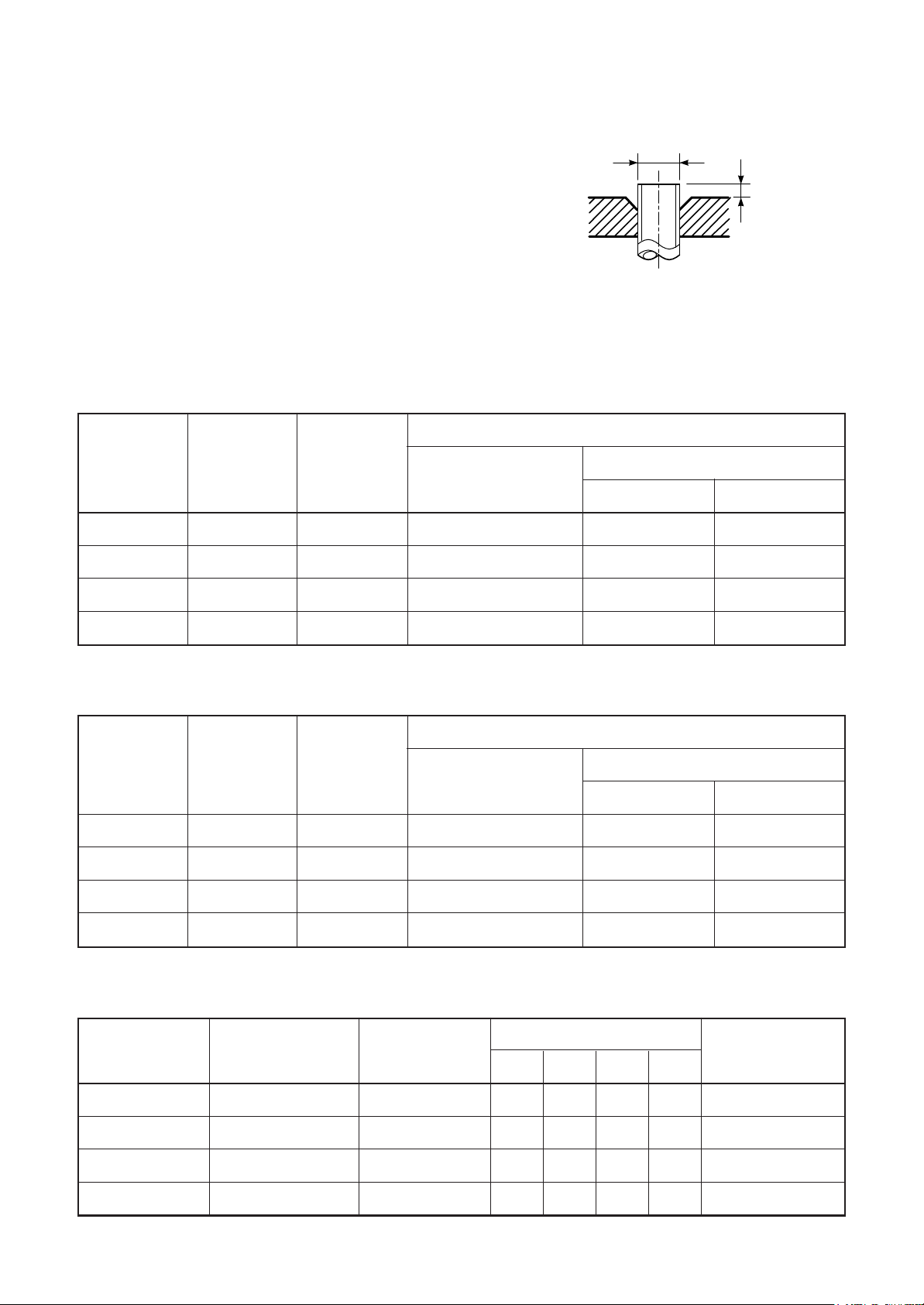
d) Flare Processing
FILE NO. SVM-15036
- 29 -
Make certain that a clamp bar and copper
pipe have been cleaned.
By means of the clamp bar, perform the flare
processing correctly.
Use either a flare tool for R410A or conventional flare tool.
Flare processing dimensions differ according
to the type of flare tool.
When using a conventional flare tool, be sure
to secure “dimension A” by using a gauge for
size adjustment.
Table 3-2-3 Dimensions related to flare processing for R410A
ØD
A
Fig. 3-2-1 Flare processing dimensions
Nominal
diameter
1/4
3/8
1/2
5/8
Nominal
diameter
1/4
3/8
Outer
diameter
(mm)
6.35
9.52
12.70
15.88
Table 3-2-4 Dimensions related to flare processing for R22
Outer
diameter
(mm)
6.35
9.52
Thickness
(mm)
0.8
0.8
0.8
1.0
Thickness
(mm)
0.8
0.8
Flare tool for R410A
clutch type
0 to 0.5 1.0 to 1.5 1.5 to 2.0
0 to 0.5 1.0 to 1.5 1.5 to 2.0
0 to 0.5 1.0 to 1.5 2.0 to 2.5
0 to 0.5 1.0 to 1.5 2.0 to 2.5
Flare tool for R22
clutch type
0 to 0.5 0.5 to 1.0 1.0 to 1.5
0 to 0.5 0.5 to 1.0 1.0 to 1.5
A (mm)
Conventional flare tool
Clutch type Wing nut type
A (mm)
Conventional flare tool
Clutch type Wing nut type
1/2
5/8
Nominal
diameter
1/4
3/8
1/2
5/8
12.70
15.88
Table 3-2-5 Flare and flare nut dimensions for R410A
Outer diameter
(mm)
6.35
9.52
12.70
15.88
0.8
1.0
Thickness
(mm)
0.8
0.8
0.8
1.0
0 to 0.5 0.5 to 1.0 1.5 to 2.0
0 to 0.5 0.5 to 1.0 1.5 to 2.0
Dimension (mm)
ABCD
9.1 9.2 6.5 13
13.2 13.5 9.7 20
16.0 16.6 12.9 23
19.0 19.7 16.0 25
Flare nut width
(mm)
17
22
26
29
Page 30
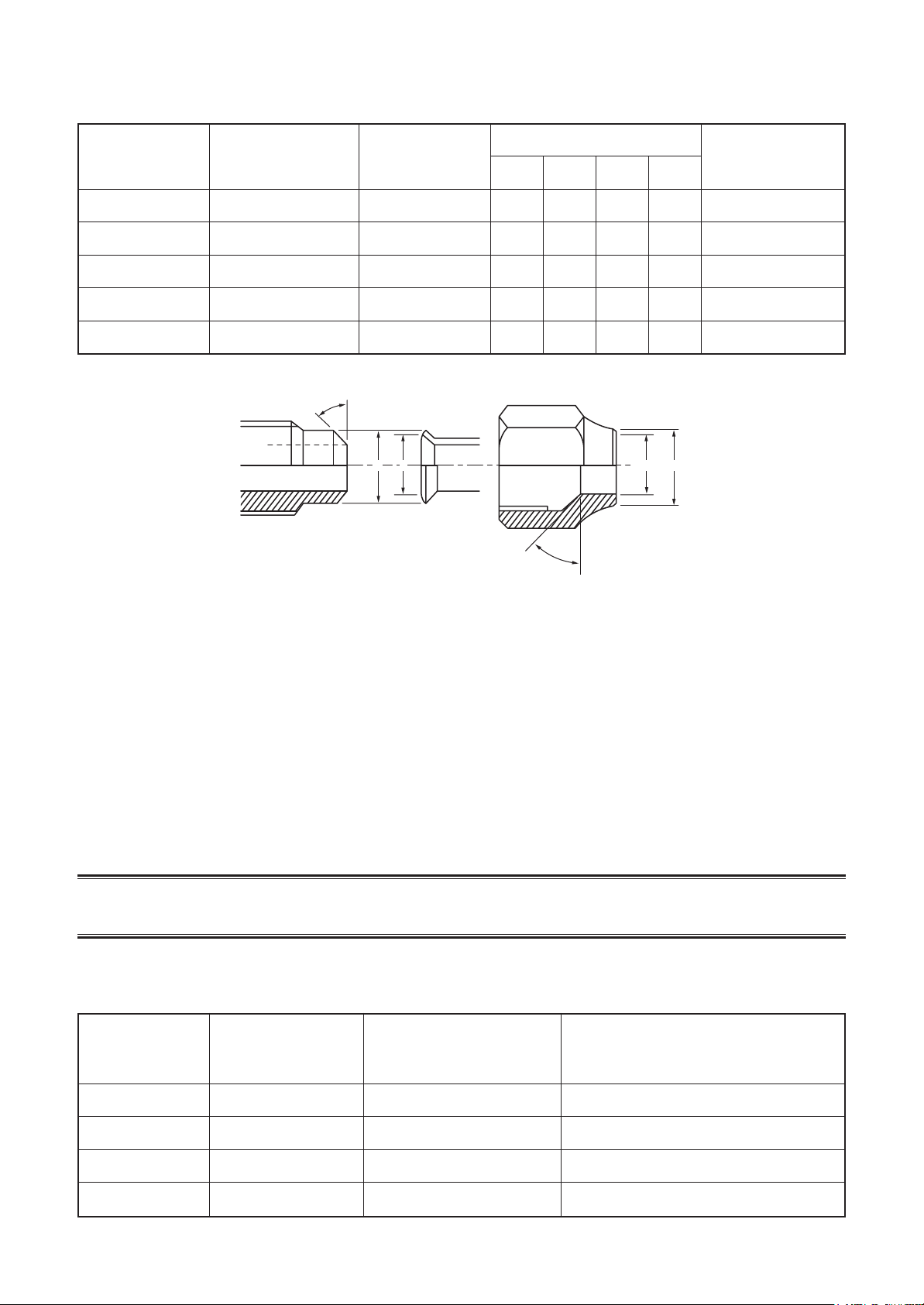
Table 3-2-6 Flare and flare nut dimensions for R22
FILE NO. SVM-15036
- 30 -
Nominal
diameter
1/4
3/8
1/2
5/8
3/4
Outer diameter
(mm)
6.35
9.52
12.70
15.88
19.05
45˚ to 46˚
Thickness
(mm)
0.8
0.8
0.8
1.0
1.0
B A
Dimension (mm)
ABCD
9.0 9.2 6.5 13
13.0 13.5 9.7 20
16.0 16.2 12.9 20
19.0 19.7 16.0 23
23.3 24.0 19.2 34
D
C
43˚ to 45˚
Flare nut width
(mm)
17
22
24
27
36
Fig. 3-2-2 Relations between flare nut and flare seal surface
2. Flare Connecting Procedures and Precautions
a) Make sure that the flare and union portions do not have any scar or dust, etc.
b) Correctly align the processed flare surface with the union axis.
c) Tighten the flare with designated torque by means of a torque wrench.
The tightening torque for R410A is the same as that for conventional R22.
Incidentally, when the torque is weak, the gas leakage may occur.
When it is strong, the flare nut may crack and may be made non-removable. When choosing the
tightening torque, comply with values designated by manufacturers. Table 3-2-7 shows reference values.
NOTE :
When applying oil to the flare surface, be sure to use oil designated by the manufacturer.
If any other oil is used, the lubricating oils may deteriorate and cause the compressor to burn out.
Table 3-2-7 Tightening torque of flare for R410A [Reference values]
Nominal
diameter
Outer diameter
(mm)
Tightening torque
N•m (kgf•cm)
Tightening torque of torque
wrenches available on the market
N•m (kgf•cm)
1/4
3/8
1/2
5/8
6.35
9.52
12.70
15.88
14 to 18 (140 to 180)
33 to 42 (330 to 420)
50 to 62 (500 to 620)
63 to 77 (630 to 770)
16 (160), 18 (180)
42 (420)
55 (550)
65 (650)
Page 31

3-3. Tools
FILE NO. SVM-15036
- 31 -
3-3-1. Required Tools
The service port diameter of packed valve of the outdoor unit in the air-water heat pump using R410A is
changed to prevent mixing of other refrigerant.
To reinforce the pressure-resisting strength, flare processing dimensions and opposite side dimension of flare
nut (For Ø12.7 copper pipe) of the refrigerant piping are lengthened.
The used refrigerating oil is changed, and mixing of oil may cause a trouble such as generation of sludge,
clogging of capillary, etc. Accordingly, the tools to be used are classified into the following three types.
1. Tools exclusive for R410A (Those which cannot be used for conventional refrigerant (R22))
2. Tools exclusive for R410A, but can be also used for conventional refrigerant (R22)
3. Tools commonly used for R410A and for conventional refrigerant (R22)
The table below shows the tools exclusive for R410A and their interchangeability.
Tools exclusive for R410A (The following tools for R410A are required.)
Tools whose specifications are changed for R410A and their interchangeability
No.
1
Flare tool
Copper pipe gauge for
2
adjusting projection margin
Torque wrench
3
(For Ø12.7)
4
Gauge manifold
5
Charge hose
6
Vacuum pump adapter
Electronic balance for
7
refrigerant charging
8
Refrigerant cylinder
9
Leakage detector
10
Charging cylinder
Used tool
Usage
Pipe flaring
Flaring by
conventional flare tool
Connection of flare nut
Evacuating, refrigerant
charge, run check, etc.
Vacuum evacuating
Refrigerant charge
Refrigerant charge
Gas leakage check
Refrigerant charge
air-water heat pump installation
R410A
Existence of Whether conventional
new equipment equipment can be
for R410A used
Ye s ∗ (Note 1)
Ye s ∗ (Note 1)
Ye s N o
Ye s N o
Ye s N o
Ye s N o
Ye s N o
Ye s N o
(Note 2) No
Conventional air-water
heat pump installation
Whether new equipment
can be used with
conventional refrigerant
Ye s
∗ (Note 1)
No
No
Ye s
Ye s
No
Ye s
No
(Note 1) When flaring is carried out for R410A using the conventional flare tools, adjustment of projection
margin is necessary. For this adjustment, a copper pipe gauge, etc. are necessary.
(Note 2) Charging cylinder for R410A is being currently developed.
In addition to the above exclusive tools, the following equipments which serve also for R22 are necessary as
the general tools.
1. Vacuum pump 7. Screwdriver (+, –)
Use vacuum pump by attaching vacuum pump adapter. 8. Spanner or Monkey wrench
2. Torque wrench (For Ø6.35, Ø9.52) 9. Hole core drill (Ø65)
3. Pipe cutter 10. Hexagon wrench (Opposite side 4mm)
4. Reamer 11. Tape measure
5. Pipe bender 12. Metal saw
6. Level vial
Also prepare the following equipments for other installation method and run check.
1. Clamp meter 3. Insulation resistance tester
2. Thermometer 4. Electroscope
General tools (Conventional tools can be used.)
Page 32

3-4. Recharging of Refrigerant
FILE NO. SVM-15036
- 32 -
When it is necessary to recharge refrigerant, charge the specified amount of new refrigerant according to the
following steps.
Recover the refrigerant, and check no refrigerant
remains in the equipment.
When the compound gauge’s pointer has indicated
–0.1 Mpa (–76 cmHg), place the handle Low in the
Connect the charge hose to packed valve service port
at the outdoor unit’s gas side.
fully closed position, and turn off the vacuum pump’s
power switch.
Connect the charge hose to the vacuum pump adapter.
Open fully both packed valves at liquid and gas sides.
Place the handle of the gauge manifold Low in the
fully opened position, and turn on the vacuum pump’s
power switch.
Then, evacuating the refrigerant in the cycle.
Keep the status as it is for 1 to 2 minutes, and ensure
that the compound gauge’s pointer does not return.
Set the refrigerant cylinder to the electronic balance,
connect the connecting hose to the cylinder and the
connecting port of the electronic balance, and charge
liquid refrigerant.
(For refrigerant charging, see the figure below.)
CAUTION
1. Never charge refrigerant exceeding the specified amount.
2. If the specified amount of refrigerant cannot be charged, charge refrigerant bit by bit in COOL mode.
3. Do not carry out additional charging.
When additional charging is carried out if refrigerant leaks, the refrigerant composition changes in the
refrigeration cycle, that is characteristics of the air conditioner changes, refrigerant exceeding the specified
amount is charged, and working pressure in the refrigeration cycle becomes abnormally high pressure, and
may cause a rupture or personal injury.
Electronic balance for refrigerant charging
Refrigerant cylinder
(with siphon)
Opened
Check valve
Opened
Open/close
valve for charging
Closed
Opened
Service port
Fig. 3-4-1 Configuration of refrigerant charging
(Outdoor unit)(Indoor unit)
Page 33

1. Be sure to make setting so that liquid can be charged.
FILE NO. SVM-15036
- 33 -
2. When using a cylinder equipped with a siphon, liquid can be charged without turning it upside down.
It is necessary for charging refrigerant under condition of liquid because R410A is mixed type of refrigerant.
Accordingly, when charging refrigerant from the refrigerant cylinder to the equipment, charge it turning the
cylinder upside down if cylinder is not equipped with siphon.
[ Cylinder with siphon ] [ Cylinder without siphon ]
Gauge manifold
OUTDOOR unit
Refrigerant
cylinder
Gauge manifold
OUTDOOR unit
cylinder
Refrigerant
Electronic
balance
R410A refrigerant is HFC mixed refrigerant.
Therefore, if it is charged with gas, the
composition of the charged refrigerant changes
and the characteristics of the equipment varies.
3-5. Brazing of Pipes
3-5-1. Materials for Brazing
1. Silver brazing filler
Silver brazing filler is an alloy mainly composed
of silver and copper.
It is used to join iron, copper or copper alloy,
and is relatively expensive though it excels in
solderability.
2. Phosphor bronze brazing filler
Phosphor bronze brazing filler is generally
used to join copper or copper alloy.
3. Low temperature brazing filler
Low temperature brazing filler is generally
called solder, and is an alloy of tin and lead.
Since it is weak in adhesive strength, do not
use it for refrigerant pipes.
Electronic
balance
Siphon
Fig. 3-4-2
1. Phosphor bronze brazing filler tends to react with
sulfur and produce a fragile compound water
solution, which may cause a gas leakage.
Therefore, use any other type of brazing filler at a hot
spring resort, etc., and coat the surface with a paint.
2. When performing brazing again at time of servicing,
use the same type of brazing filler.
3-5-2. Flux
1. Reason why flux is necessary
• By removing the oxide film and any foreign matter
on the metal surface, it assists the flow of brazing
filler.
• In the brazing process, it prevents the metal
surface from being oxidized.
• By reducing the brazing filler’s surface tension,
the brazing filler adheres better to the treated metal.
Page 34

2. Characteristics required for flux
FILE NO. SVM-15036
- 34 -
• Activated temperature of flux coincides with
the brazing temperature.
• Due to a wide effective temperature range, flux
is hard to carbonize.
• It is easy to remove slag after brazing.
• The corrosive action to the treated metal and
brazing filler is minimum.
• It excels in coating performance and is harmless to the human body.
As the flux works in a complicated manner as
described above, it is necessary to select an
adequate type of flux according to the type and
shape of treated metal, type of brazing filler and
brazing method, etc.
3. Types of flux
• Noncorrosive flux
Generally, it is a compound of borax and boric
acid. It is effective in case where the brazing
temperature is higher than 800°C.
• Activated flux
Most of fluxes generally used for silver brazing
are this type.
It features an increased oxide film removing
capability due to the addition of compounds
such as potassium fluoride, potassium chloride
and sodium fluoride to the borax-boric acid
compound.
4. Piping materials for brazing and used
brazing filler/flux
3-5-3. Brazing
As brazing work requires sophisticated techniques,
experiences based upon a theoretical knowledge, it
must be performed by a person qualified.
In order to prevent the oxide film from occurring in
the pipe interior during brazing, it is effective to
proceed with brazing while letting dry Nitrogen gas
(N2) flow.
Never use gas other than Nitrogen gas.
1. Brazing method to prevent oxidation
1) Attach a reducing valve and a flow-meter to
the Nitrogen gas cylinder.
2) Use a copper pipe to direct the piping material, and attach a flow-meter to the cylinder.
3) Apply a seal onto the clearance between the
piping material and inserted copper pipe for
Nitrogen in order to prevent backflow of the
Nitrogen gas.
4) When the Nitrogen gas is flowing, be sure to
keep the piping end open.
5) Adjust the flow rate of Nitrogen gas so that it
is lower than 0.05 m3/Hr or 0.02 MPa
(0.2kgf/cm2) by means of the reducing valve.
6) After performing the steps above, keep the
Nitrogen gas flowing until the pipe cools
down to a certain extent (temperature at
which pipes are touchable with hands).
7) Remove the flux completely after brazing.
Piping material
Copper - Copper
Copper - Iron
Iron - Iron
Used brazing filler
Phosphor copper
Silver
Silver
Used flux
Do not use
Paste flux
Vapor flux
1. Do not enter flux into the refrigeration cycle.
2. When chlorine contained in the flux remains
within the pipe, the lubricating oil deteriorates.
Therefore, use a flux which does not contain
chlorine.
3. When adding water to the flux, use water which
does not contain chlorine
(e.g. distilled water or ion-exchange water).
4. Remove the flux after brazing.
M
Flow meter
Stop valve
Nitrogen gas
cylinder
From Nitrogen cylinder
Pipe
Nitrogen
gas
Rubber plug
Fig. 3-5-1 Prevention of oxidation during brazing
Page 35

4-1. Outdoor Unit
FILE NO. SVM-15036
- 35 -
RAS-5M34S3AV-E, -A, -TR
365
Anchor b olt long hole pitch
17.5 17.5
320 30
890
24
165 534
148 581
2-dia.12x17 U-shape hole
(For dia.8-10 anchor bolt)
A leg part
dia.551
438
4. CONSTRUCTION VIEWS
600 150
2-dia.12x17 long hole
(For dia.8-10 anchor bolt)
900
55052
C
L
B leg part
411
Gravity position
Fan guard
Hanger
Liquid valve
Service port
Gas valve
193
157
Connecting pipe port :
Connecting pipe dia.6.35
Connecting pipe dia.9.52
Connecting pipe dia.6.35
Connecting pipe dia.9.52
Connecting pipe dia.6.35
Connecting pipe dia.9.52
Connecting pipe dia.6.35
Connecting pipe dia.12.7
Connecting pipe dia.6.35
Connecting pipe dia.12.7
E unit
D unit
C unit
B unit
A unit
Gravity position
400
195
327
60 178 178 178
68 518
67
74
191
71
Outdoor
air temperature sensor Fin guard
Hanger
5-drain long hole
dia.20x88
375
45
Drain hole
dia.25
260250
Gravity position
322
Mounting hole sold separately
12-dia.3 emboss
380
116
34
600
12
2-R10
Outside line
of product
80
87
56.5
34.5
72.5
83
11
11
65
Knock out
40
2.5
R6
365
Detailed A leg part
Outside line
17
600
of product
R6
12
56.5
365
40
Detailed B leg part
94.2 52 52 52 52 52 52 52 52 52
Page 36

5. WIRING DIAGRAM
FILE NO. SVM-15036
- 36 -
5-1.
Outdoor Unit
RAS-5M34S3AV-
A
MS
FAN MOTOR
MS
COMPRESSOR
4WAY VALVE COIL
PMV E
PMV D
PMV C
PMV B
PMV A
M
M
M
M
M
BLK
4WV
WHI
123
TO
INDOOR
UNIT C
3
3
5
5
5
5
5
REACTOR
GRN
BLK
11
2
2
3 3
MCC-1436
CN200
CN201
CN202
1
CN701
(WHI)
4
+ + +
C11
C12
C10
1
2
CN704
3
4
(BLK)
6
1
2
CN703
3
4
(BLU)
6
1
2
CN702
3
4
(GRN)
6
1
2
CN701
3
4
(RED)
6
1
2
CN700
3
4
(YEL)
6
CN01
(RED)
WHI
WHI
BLU
WHI
BLK
213 213
TO
INDOOR
UNIT D
TO
INDOOR
UNIT E
P09
CN300
3
MAIN P.C.
BOARD
(MCC-1571)
POWER
SUPPLY
CIRCUIT
F100
T3.15A
250V
F01
25A
250V
L/F
4
1
BLK
GRY
F01
T3.15A
250V
P05
WHI
BLK
CN802
(BLU)
1 2 435
(BLU)
P04
P03
5
CN800
(WHI)
12
345 12 345
CN804 CN802
(WHI)
CONTROL
P.C.BOARD
(MCC-5071)
3
312 12
TO
INDOOR
UNIT A
CN609
(BLU)
F03
T10A
250V
(WHI)
5
CN608
CN607
CN606
CN605
CN604
CN603
CN602
CN601
CN600
CN609
(PNK)
P025P01
3 1
DEMAND
P.C.BOARD
(MCC-1653)
YEL RED
WHI
TO
INDOOR
UNIT B
CN690
CN04
(BLK)
(BLU)
(GRN)
(RED)
(YEL)
(WHI)
(WHI)
(WHI)
(WHI)
21
3
P04
P05
P06
P07
1
2
P01
P02
1
3
5
7
P07
1
2
1
2
1
2
1
2
1
2
1
3
1
2
1
2
1
3
CN105
(WHI)
CN100
(WHI)
L
POWER
SUPPLY
220-240V 50Hz
220V 60Hz
REACTOR
REACTOR
THERMOSTAT
FOR
COMPRESSOR
HIGH PRESSURE
SWITCH
RED
WHI
WHI
BLK
t°
TGE
TGD
t°
TGC
t°
t°
TGB
t°
TGA
TS
t°
TO
t°
TE
t°
TD
t°
T-01
231 21
CN102
CN101
(WHI)
(YEL)
F-D
T3.15A
250V
123
RED
WHI
N
EARTH
SCREW
t°>
P<
P02
CN01
(BLK)
123 4
WHI
RED
1234
COM
DRM1
TO
DRED
BLU
BLK
DRM2
DRM3
COLOR IDENTIFICATION
BLK:BLACK
BLU:BLUE
RED:RED
PNK:PINK
Symbol
PMV
TD
TE
TO
TS
TGA TGE GAS SIDE PIPE TEMP. SENSOR A E
L / F LINE FILTER
GRN:GREEN
WHI:WHITE
YEL:YELLOW
Part name
PULSE MOTOR VALVE
DISCHARGE PIPE TEMP. SENSOR
CONDENSER PIPE TEMP. SENSOR
OUTDOOR TEMP. SENSOR
SUCTION PIPE TEMP. SENSOR
Page 37

5-2. Outdoor Unit
FILE NO. SVM-15036
- 37 -
RAS-5M34S3AV-E, -TR
MS
FAN MOTOR
MS
COMPRESSOR
4WV
4WAY VALVE COIL
PMV E
M
PMV D
M
PMV C
M
PMV B
M
PMV A
M
BLK
3
3
5
5
5
5
5
REACTOR
WHI WHI
GRN
BLK
3
1 2
TO
INDOOR
UNIT C
1 1
3 3
MCC-1436
CN200
CN201
CN202
1
CN701
(WHI)
4
+ + +
C11
C12
1
2
3
CN704
4
6
1
2
3
CN703
4
6
1
2
3
CN702
4
6
1
2
3
CN701
4
6
1
2
3
CN700
4
6
12
TO
INDOOR
UNIT D
22
3
POWER
SUPPLY
CIRCUIT
L/F
C10
CN800
(WHI)
12
4 21435
345 12 345
CN804
(WHI)
(BLK)
(BLU)
CONTROL
P.C.BOARD
(GRN)
(MCC-5071)
(RED)
(YEL)
CN01
(RED)
WHI
BLU
WHI
BLK
3
12
TO
INDOOR
UNIT E
F100
T3.15A
250V
F01
25A
250V
CN802
(BLU)
CN802
(BLU)
F01
T3.15A
250V
13
BLK
GRY
3
P09
CN300
MAIN P.C.
BOARD
(MCC-1571 )
F03
T10A
250V
5
P05
P04
WHI
BLK
1 2
TO
INDOOR
UNIT A
CN609
(BLU)
CN690
CN04
(WHI)
CN608
(BLK)
CN607
(BLU)
CN606
(GRN)
CN605
(RED)
CN604
(YEL)
CN603
(WHI)
CN602
(WHI)
CN601
(WHI)
CN600
(WHI)
P03
P02
5
5
3
P04
P05
P06
P07
1
2
1
3
5
7
P07
P01
YEL
TO
INDOOR
UNIT B
1
2
1
2
1
2
1
2
1
2
1
3
1
2
1
2
1
3
1
P01
P02
WHI
2
RED
WHI
WHI
BLK
3
THERMOSTAT
FOR
COMPRESSOR
HIGH PRESSURE
SWITCH
TGE
t°
TGD
t°
TGC
t°
TGB
t°
TGA
t°
TS
t°
TO
t°
TE
t°
TD
t°
RED
L
N
POWER
SUPPLY
220-240V 50Hz
220V 60Hz
REACTOR
REACTOR
t°>
P<
EARTH
SCREW
COLOR IDENTIFICATION
BLK:BLACK
BLU:BLUE
RED:RED
PNK:PINK
Symbol
PMV
TD
TE
TO
TS
TGA TGE GAS SIDE PIPE TEMP. SENSOR A E
L / F LINE FILTER
GRN:GREEN
WHI:WHITE
YEL:YELLOW
Part name
PULSE MOTOR VALVE
DISCHARGE PIPE TEMP. SENSOR
CONDENSER PIPE TEMP. SENSOR
OUTDOOR TEMP. SENSOR
SUCTION PIPE TEMP. SENSOR
Page 38

5-3. Outdoor Unit
FILE NO. SVM-15036
- 38 -
RAS-5M34S3AV-A
Wiring between DRED (Demand response enabling device) and Outdoor Unit
This model supports DRM1 DRM2 DRM3.
AS/NZS 4755 DRM1
■ Important notice
• Install in accordance with the wiring rules (AS/NZS 3000).
• The precautions described below include important items regarding safety.
Observe them without fail.
• The manufacturer shall not assume any liability for the damage caused by not observing the description of this manual.
DRM2 DRM3
WARNING
• Turn off the main power supply switch or breaker before attempting installation.
Make sure all power switches are off. Failure to do so may cause electric shock.
• Connect the connecting wire correctly.
If the connecting wire is incorrect, electric parts may be damaged.
•
Ensure that all terminals are securely fi xed, so preventing any external forces having a negative
effect on the terminals.
• Do not connect the DRED mains cable to the terminal block of the outdoor unit
(Power supply and Indoor/Outdoor connecting).
Improper installation may result in fi re.
Connect the demand connecting wires and relay connector (RJ45) so that they do not come
•
into contact with the refrigerant cycle parts or refrigerant pipes.
Wire breakage or water intrusion may cause electric shock or fi re.
• Do not screw the DRED signal receiver directly to the outdoor unit.
The screw may damage the internal parts and cause an electric shock, fire or refrigerant leak.
CAUTION
• Wear heavy gloves during the installation work to avoid injury.
Connection procedure
■
• This air conditioner complies with AS/NZS 4755.3.1.
• DRM available: DRM1, DRM2, DRM3
• The terminal block meets ELV requirements.
WARNING
Do not connect the DRED mains cable to
•
the terminal block of the outdoor unit
(Power supply and Indoor/Outdoor
connecting). Improper installation may
result in fi re.
• For the power supply of the DRED,
prepare exclusive power supply
separated from that of the outdoor unit.
WARNING
Connect the wire (4-wire) with a round
terminal to the Demand section (COM,
DRM1, DRM2, DRM3) on the terminal block.
Trans-
former
Demand response interface
CN101
CN102
COM DRM1 DRM2 DRM3
COM DRM1 DRM2 DRM3
DRED
COM DRM1 DRM2 DRM3
CN100
MCC-1653
CN105
Locally procured
LN
Power supply
Outdoor control
P.C. board
123
Indoor (A~E) unit
Connecting
Page 39

Air conditioner demand response
FILE NO. SVM-15036
- 39 -
Demand response mode
DRM1
DRM2
DRM3
*1: E30m = total electrical energy (kWh) used by the air conditioner for all purposes (including compressors, controls and fans) over a 30 min period.
*2: * = rated input electrical power of the air conditioner (kW) at rated capacity in the mode in which it is operating during the demand response event
(i.e.cooling or heating).
■ Wiring procedure
1. Securely fasten the demand connecting wires with the cord clamp located at the upper portion of the terminal block so that no external force is applied to the
terminal.
* The demand connecting wires having a relay connector (RJ45) should be wired in such a manner as to prevent water intrusion into the relay connector.
2. Bundle the demand connecting wires with indoor/outdoor connecting wires using a fi xing band (locally procured).
Description
Compressor off
E30m ≤ R × 0.50 × 0.5
E30m ≤ R × 0.75 × 0.5
Cord clamp
DRED terminal block connections
Banding band
Page 40

6. SPECIFICATIONS OF ELECTRICAL PARTS
FILE NO. SVM-15036
- 40 -
6-1. Outdoor Unit
RAS-5M34S3AV-E, -A, -TR
No.
1
Compressor
2
Outdoor fan motor
3
Reactor
4
Reactor
5
4-way valve coil
6
PMV coil
7
P.C. board (Main PCB)
8
P.C. board (Control PCB)
9
P.C. board (Fan motor connection)
10
Fuse (Mounted on P.C. board MCC-1571)
11
Fuse (Mounted on P.C. board MCC-1571)
12
Fuse (Mounted on P.C. board MCC-1571, MCC-5071)
13
Outdoor temp. sensor (TO sensor)
14
Evaporator temp. sensor (Te sensor)
15
Discharge temp. sensor (Td sensor)
Parts name
Model name
DA270A2T-20LD
WDF-340-A100-1
CH-56-3Z-T
CH-76-TM1
5TF-H01AP1874A1
UKV-A039
MCC-1571
MCC-5071
MCC-1436
—
—
—
—
—
—
Rating
—
Output 100 W
5.8 mH, 18.5 A
9.9 mH, 1 A
AC 200–240 V
DC 12 V
AC 220–240 V
AC 220–240 V
AC 220–240V
AC 250V, 25 A
AC 250V, 10 A
AC 250V, 3.15 A
10 kΩ (25°C)
10 kΩ (25°C)
50 kΩ (25°C)
16
Suction temp. sensor (Ts sensor)
17
Temp. sensor at A room gas side (TGa-sensor)
18
Temp. sensor at B room gas side (TGb-sensor)
19
Temp. sensor at C room gas side (TGc-sensor)
20
Temp. sensor at D room gas side (TGd-sensor)
21
Temp. sensor at E room gas side (TGe-sensor)
22
Compressor thermo.
23
Terminal block (9P)
—
—
—
—
—
—
CS-12AL
—
10 kΩ (25°C)
10 kΩ (25°C)
10 kΩ (25°C)
10 kΩ (25°C)
10 kΩ (25°C)
10 kΩ (25°C)
ON: 90°C, OFF: 125°C
AC 250 V, 20 A
Page 41

7. REFRIGERANT CYCLE DIAGRAM
FILE NO. SVM-15036
- 41 -
High Pressure switch
DA270A2T-20LD
Outdoor unit
NOTE :
• You need not add refrigerant if the piping length is 40m or less.
• If the length exceeds 41m, add 20g of refrigerant per 1 meter over.
• Connection of only one indoor unit is unavailable. Two or more indoor units should be connected.
Page 42

7-2. Operation Data
FILE NO. SVM-15036
- 42 -
Outdoor Unit : RAS-5M34S3AV-E,-A,-TR
<Cooling>
Temperature
condition
Indoor Outdoor A B C D E P (MP) T1 (°C) T2 (°C)
27 / 19 35 / – 13 13 07 — — 0.8 to 1.0 11 to 13 51 to 53 High 49
No. of
operating
units
1 unit 07 — — — — 0.9 to 1.1 15 to 17 36 to 42 High 16
2 units 07 07 — — — 0.8 to 1.0 10 to 1 2 47 to 49 High 35
3 units 07 07 07 — — 0.8 to 1.0 11 to 1 3 51 to 53 High 49
10 — — — — 0 .8 to 1.0 12 to 14 36 to 42 High 19
13 — — — — 0 .7 to 0.9 10 to 12 36 to 44 High 31
16 — — — — 0 .6 to 0.8 9 to 11 36 to 46 High 40
18 — — — — 0 .6 to 0.8 10 to 12 36 to 47 High 45
22 — — — — 0 .6 to 0.8 8 to 10 36 to 47 High 47
24 — — — — 0 .6 to 0.8 8 to 10 36 to 47 High 60
10 07 — — — 0.8 t o 1.0 10 to 12 47 to 49 High 35
13 07 — — — 0.8 t o 1.0 10 to 12 47 to 49 High 37
16 07 — — — 0.8 t o 1.0 10 to 12 47 to 49 High 40
18 07 — — — 0.8 t o 1.0 10 to 12 47 to 49 High 43
22 07 — — — 0.8 t o 1.0 10 to 12 49 to 51 High 46
24 07 — — — 0.7 t o 0.9 9 to 11 51 to 53 High 48
10 10 — — — 0.8 t o 1.0 10 to 12 47 to 49 High 35
13 10 — — — 0.8 t o 1.0 10 to 12 47 to 49 High 40
16 10 — — — 0.8 t o 1.0 10 to 12 49 to 51 High 43
18 10 — — — 0.8 t o 1.0 10 to 12 49 to 51 High 46
22 10 — — — 0.7 t o 0.9 9 to 11 51 to 53 High 48
24 10 — — — 0.7 t o 0.9 9 to 11 51 to 53 High 51
13 13 — — — 0.8 t o 1.0 10 to 12 47 to 49 High 35
16 13 — — — 0.7 t o 0.9 9 to 11 51 to 53 High 51
18 13 — — — 0.7 t o 0.9 9 to 11 51 to 53 High 51
22 13 — — — 0.7 t o 0.9 9 to 11 51 to 53 High 51
24 13 — — — 0.7 t o 0.9 9 to 11 51 to 53 High 51
16 16 — — — 0.7 t o 0.9 9 to 11 52 to 54 High 51
18 16 — — — 0.7 t o 0.9 9 to 11 52 to 54 High 51
22 16 — — — 0.7 t o 0.9 9 to 11 52 to 54 High 51
24 16 — — — 0.7 t o 0.9 9 to 11 52 to 54 High 51
18 18 — — — 0.7 t o 0.9 9 to 11 52 to 54 High 51
22 18 — — — 0.7 t o 0.9 9 to 11 52 to 54 High 51
24 18 — — — 0.7 t o 0.9 9 to 11 52 to 54 High 51
22 22 — — — 0.7 t o 0.9 9 to 11 52 to 54 High 51
22 24 — — — 0.7 t o 0.9 9 to 11 52 to 54 High 51
24 24 — — — 0.7 t o 0.9 9 to 11 52 to 54 High 51
10 07 07 — — 0.8 to 1.0 11 to 13 51 to 53 High 49
13 07 07 — — 0.8 to 1.0 11 to 13 51 to 53 High 49
16 07 07 — — 0.8 to 1.0 11 to 13 51 to 53 High 49
18
22 07 07 — — 0.8 to 1.0 11 to 13 51 to 53 High 49
24 07 07 — — 0.8 to 1.0 11 to 13 51 to 53 High 49
10 10 07 — — 0.8 to 1.0 11 to 13 51 to 53 High 49
13 10 07 — — 0.8 to 1.0 11 to 13 51 to 53 High 49
16 10 07 — — 0.8 to 1.0 11 to 13 51 to 53 High 49
18 10 07 — — 0.8 to 1.0 11 to 13 51 to 53 High 49
22 10 07 — — 0.8 to 1.0 11 to 13 51 to 53 High 49
24 10 07 — — 0.8 to 1.0 11 to 13 51 to 53 High 49
16 13 07 — — 0.8 to 1.0 11 to 13 51 to 53 High 49
18 13 07 — — 0.8 to 1.0 11 to 13 51 to 53 High 49
22 13 07 — — 0.8 to 1.0 11 to 13 51 to 53 High 49
24 13 07 — — 0.8 to 1.0 11 to 13 51 to 53 High 49
16 16 07 — — 0.8 to 1.0 11 to 13 51 to 53 High 49
18 16 07 — — 0.8 to 1.0 11 to 13 51 to 53 High 49
22 16 07 — — 0.8 to 1.0 11 to 13 51 to 53 High 49
24 16 07 — — 0.8 to 1.0 11 to 13 51 to 53 High 49
18 18 07 — — 0.8 to 1.0 11 to 13 51 to 53 High 49
22 18 07 — — 0.8 to 1.0 11 to 13 51 to 53 High 49
24 18 07 — — 0.8 to 1.0 11 to 13 51 to 53 High 49
10 10 10 — — 0.8 to 1.0 11 to 13 51 to 53 High 49
13 10 10 — — 0.8 to 1.0 11 to 13 51 to 53 High 49
16 10 10 — — 0.8 to 1.0 11 to 13 51 to 53 High 49
18 10 10 — — 0.8 to 1.0 11 to 13 51 to 53 High 49
22 10 10 — — 0.8 to 1.0 11 to 13 51 to 53 High 49
24 10 10 — — 0.8 to 1.0 11 to 13 51 to 53 High 49
13 13 10 — — 0.8 to 1.0 11 to 13 51 to 53 High 49
16 13 10 — — 0.8 to 1.0 11 to 13 51 to 53 High 49
18 13 10 — — 0.8 to 1.0 11 to 13 51 to 53 High 49
22 13 10 — — 0.8 to 1.0 11 to 13 51 to 53 High 49
24 13 10 — — 0.8 to 1.0 11 to 13 51 to 53 High 49
16 16 10 — — 0.8 to 1.0 11 to 13 51 to 53 High 49
18 16 10 — — 0.8 to 1.0 11 to 13 51 to 53 High 49
22 16 10 — — 0.8 to 1.0 11 to 13 51 to 53 High 49
24 16 10 — — 0.8 to 1.0 11 to 13 51 to 53 High 49
18 18 10 — — 0.8 to 1.0 11 to 13 51 to 53 High 49
13 13 13 — — 0.8 to 1.0 11 to 13 51 to 53 High 49
16 13 13 — — 0.8 to 1.0 11 to 13 51 to 53 High 49
18 13 13 — — 0.8 to 1.0 11 to 1
22 13 13 — — 0.8 to 1.0 11 to 13 51 to 53 High 49
24 13 13 — — 0.8 to 1.0 11 to 13 51 to 53 High 49
16 16 13 — — 0.8 to 1.0 11 to 13 51 to 53 High 49
16 16 16 — — 0.8 to 1.0 11 to 13 51 to 53 High 49
18 16 13 — — 0.8 to 1.0 11 to 13 51 to 53 High 49
22 16 13 — — 0.8 to 1.0 11 to 13 51 to 53 High 49
24 16 13 — — 0.8 to 1.0 11 to 13 51 to 53 High 49
18 18 13 — — 0.8 to 1.0 11 to 13 51 to 53 High 49
22 18 10 — — 0.8 to 1.0 11 to 13 51 to 53 High 49
22 18 13 — — 0.8 to 1.0 11 to 13 51 to 53 High 49
24 18 10 — — 0.8 to 1.0 11 to 13 51 to 53 High 49
24 18 13 — — 0.8 to 1.0 11 to 13 51 to 53 High 49
22 22 07 — — 0.8 to 1.0 11 to 13 51 to 53 High 49
22 22 10 — — 0.8 to 1.0 11 to 13 51 to 53 High 49
24 22 07 — — 0.8 to 1.0 11 to 13 51 to 53 High 49
24 22 10 — — 0.8 to 1.0 11 to 13 51 to 53 High 49
24 24 07 — — 0.8 to 1.0 11 to 13 51 to 53 High 49
24 24 10 — — 0.8 to 1.0 11 to 13 51 to 53 High 49
Indoor unit
07 07 — — 0.8 to 1.0 11 to 13 51 to 5 3 High 49
Standard
pressure
Heat exchanger
pipe temperature
3 51 to 53 High 49
Indoor
fan
Compressor
revolution
(rps)
NOTES :
1. Measure surface temperature of heat exchanger pipe around of heat exchanger path U bent. (Thermistor thermometer)
2. Connecting piping condition : 5 meters × 5 units (5m/each indoor unit)
Page 43

<Cooling> (Continued)
FILE NO. SVM-15036
- 43 -
Temperature
condition
Indoor Outdoor A B C D E P (MP) T1 (°C) T2 (°C)
27 / 19 35 / –
No. of
operating
units
4 units 07 07 07 07 — 0.9 to 1.1 12 to 14 51 to 53 High 50
10 07 07 0 7 — 0.9 to 1.1 12 to 14 51 to 53 High 50
13 07 07 0 7 — 0.9 to 1.1 12 to 14 51 to 53 High 50
16 07 07 0 7 — 0.9 to 1.1 12 to 14 51 to 53 High 50
18 07 07 0 7 — 0.9 to 1.1 12 to 14 51 to 53 High 50
22 07 07 0 7 — 0.9 to 1.1 12 to 14 51 to 53 High 50
24 07 07 0 7 — 0.9 to 1.1 12 to 14 51 to 53 High 50
10 10 07 0 7 — 0.9 to 1.1 12 to 14 51 to 53 High 50
13 10 07 0 7 — 0.9 to 1.1 12 to 14 51 to 53 High 50
16 10 07 0 7 — 0.9 to 1.1 12 to 14 51 to 53 High 50
18 10 07 0 7 — 0.9 to 1.1 12 to 14 51 to 53 High 50
22 10 07 0 7 — 0.9 to 1.1 12 to 14 51 to 53 High 50
24 10 07 0 7 — 0.9 to 1.1 12 to 14 51 to 53 High 50
13 13 07 0 7 — 0.9 to 1.1 12 to 14 51 to 53 High 50
16 13 07 0 7 — 0.9 to 1.1 12 to 14 51 to 53 High 50
18 13 07 0 7 — 0.9 to 1.1 12 to 14 51 to 53 High 50
22 13 07 0 7 — 1.0 to 1.2 15 to 17 51 to 53 High 53
24 13 07 0 7 — 1.0 to 1.2 15 to 17 51 to 53 High 55
16 16 07 0 7 — 0.9 to 1.1 12 to 14 51 to 53 High 50
18 16 07 0 7 — 1.0 to 1.2 15 to 17 51 to 53 High 53
22 16 07 0 7 — 1.0 to 1.2 15 to 17 51 to 53 High 55
24 16 07 0 7 — 1.0 to 1.2 15 to 17 51 to 53 High 55
18 18 07 0 7 — 1.0 to 1.2 15 to 17 51 to 53 High 55
22 18 07 0 7 — 1.0 to 1.2 15 to 17 51 to 53 High 55
24 18 07 0 7 — 1.0 to 1.2 15 to 17 51 to 53 High 55
10 10 10 0 7 — 0.9 to 1.1 12 to 14 51 to 53 High 50
13 10 10 0 7 — 0.9 to 1.1 12 to 14 51 to 53 High 50
16 10 10 0 7 — 0.9 to 1.1 12 to 14 51 to 53 High 50
18 10 10 0 7 — 0.9 to 1.1 12 to 14 51 to 53 High 50
22 10 10 0 7 — 0.9 to 1.1 12 to 14 51 to 53 High 50
24 10 10 0 7 — 1.0 to 1.2 15 to 17 51 to 53 High 53
13 13 10 0 7 — 0.9 to 1.1 12 to 14 51 to 53 High 50
16 13 10 0 7 — 0.9 to 1.1 12 to 14 51 to 53 High 50
18 13 10 0 7 — 0.9 to 1.1 12 to 14 51 to 53 High 50
22 13 10 0 7 — 1.0 to 1.2 15 to 17 51 to 53 High 55
24 13 10 0 7 — 1.0 to 1.2 15 to 17 51 to 53 High 55
16 16 10 0 7 — 1.0 to 1.2 15 to 17 51 to 53 High 53
18 16 10 0 7 — 1.0 to 1.2 15 to 17 51 to 53 High 55
22 16 10 0 7 — 1.0 to 1.2 15 to 17 51 to 53 High 55
24 16 10 0 7 — 1.
18 18 10 0 7 — 1.0 to 1.2 15 to 17 51 to 53 High 55
22 18 10 0 7 — 1.0 to 1.2 15 to 17 51 to 53 High 55
24 18 10 0 7 — 1.0 to 1.2 15 to 17 51 to 53 High 55
13 13 13 0 7 — 1.0 to 1.2 15 to 17 51 to 53 High 53
16 13 13 0 7 — 1.0 to 1.2 15 to 17 51 to 53 High 55
18 13 13 0 7 — 1.0 to 1.2 15 to 17 51 to 53 High 55
22 13 13 0 7 — 1.0 to 1.2 15 to 17 51 to 53 High 55
24 13 13 0 7 — 1.0 to 1.2 15 to 17 51 to 53 High 55
16 16 13 0 7 — 1.0 to 1.2 15 to 17 51 to 53 High 55
18 16 13 0 7 — 1.0 to 1.2 15 to 17 51 to 53 High 55
22 16 13 0 7 — 1.0 to 1.2 15 to 17 51 to 53 High 55
24 16 13 0 7 — 1.0 to 1.2 15 to 17 51 to 53 High 55
18 18 13 0 7 — 1.0 to 1.2 15 to 17 51 to 53 High 55
22 18 13 0 7 — 1.0 to 1.2 15 to 17 51 to 53 High 55
24 18 13 0 7 — 1.0 to 1.2 15 to 17 51 to 53 High 55
10 10 10 1 0 — 0.9 to 1.1 12 to 14 51 to 53 High 50
13 10 10 1 0 — 0.9 to 1.1 12 to 14 51 to 53 High 50
16 10 10 1 0 — 0.9 to 1.1 12 to 14 51 to 53 High 50
18 10 10 1 0 — 0.9 to 1.1 12 to 14 51 to 53 High 50
22 10 10 1 0 — 1.0 to 1.2 15 to 17 51 to 53 High 53
24 10 10 1 0 — 1.0 to 1.2 15 to 17 51 to 53 High 55
13 13 10 1 0 — 0.9 to 1.1 12 to 14 51 to 53 High 50
16 13 10 1 0 — 1.0 to 1.2 15 to 17 51 to 53 High 53
22 13 10 1 0 — 1.0 to 1.2 15 to 17 51 to 53 High 55
24 13 10 1 0 — 1.0 to 1.2 15 to 17 51 to 53 High 55
16 16 10 1 0 — 1.0 to 1.2 15 to 17 51 to 53 High 55
18 13 10 1 0 — 1.0 to 1.2 15 to 17 51 to 53 High 55
22 16 10 1 0 — 1.0 to 1.2 15 to 17 51 to 53 High 55
24 16 10 1 0 — 1.0 to 1.2 15 to 17 51 to 53 High 55
18 16 10 1 0 — 1.0 to 1.2 15 to 17 51 to 53 High 55
18 18 10 1 0 — 1.0 to 1.2 15 to 17 51 to 53 High 55
22 18 10 1 0 — 1.0 to 1.2 15 to 17 51 to 53 High 55
24 18 10 1 0 — 1.0 to 1.2 15 to 17 51 to 53 High 55
13 13 13 1 0 — 1.0 to 1.2 15 to 17 51 to 53 High 55
16 13 13 1 0 — 1.0 to 1.2 15 to 17 51 to 53 High 55
18 13 13 1 0 — 1.0 to 1.2 15 to 17 51 to 53 High 55
22 13 13 1 0 — 1.0 to 1.2 15 to 17 51 to 53 High 55
24 13 13 1 0 — 1.0 to 1.2 15 to 17 51 to 53 High 55
18 16 13 1 0 — 1.0 to 1.2 15 to 17 51 to 53 High 55
22 16
24 16 13 1 0 — 1.0 to 1.2 15 to 17 51 to 53 High 55
18 18 13 1 0 — 1.0 to 1.2 15 to 17 51 to 53 High 55
22 18 13 1 0 — 1.0 to 1.2 15 to 17 51 to 53 High 55
24 18 13 1 0 — 1.0 to 1.2 15 to 17 51 to 53 High 55
13 13 13 1 3 — 1.0 to 1.2 15 to 17 51 to 53 High 55
16 13 13 1 3 — 1.0 to 1.2 15 to 17 51 to 53 High 55
18 13 13 1 3 — 1.0 to 1.2 15 to 17 51 to 53 High 55
22 13 13 1 3 — 1.0 to 1.2 15 to 17 51 to 53 High 55
24 13 13 1 3 — 1.0 to 1.2 15 to 17 51 to 53 High 55
16 16 13 1 3 — 1.0 to 1.2 15 to 17 51 to 53 High 55
18 16 13 1 3 — 1.0 to 1.2 15 to 17 51 to 53 High 55
22 16 13 1 3 — 1.0 to 1.2 15 to 17 51 to 53 High 55
24 16 13 1 3 — 1.0 to 1.2 15 to 17 51 to 53 High 55
18 18 13 1 3 — 1.0 to 1.2 15 to 17 51 to 53 High 55
22 18 13 1 3 — 1.0 to 1.2 15 to 17 51 to 53 High 55
24 18 13 1 3 — 1.0 to 1.2 15 to 17 51 to 53 High 55
Indoor unit
13 10 — 1.0 to 1.2 15 to 1 7 51 to 53 High 55
Standard
pressure
0 to 1.2 15 to 17 51 to 53 High 55
Heat exchanger
pipe temperature
Indoor
fan
Compressor
revolution
(rps)
NOTES :
1. Measure surface temperature of heat exchanger pipe around of heat exchanger path U bent. (Thermistor thermometer)
2. Connecting piping condition : 5 meters × 5 units (5m/each indoor unit)
Page 44

<Cooling> (Continued)
FILE NO. SVM-15036
- 44 -
Temperature
condition
Indoor
27 / 19 35 / –
Outdoor
No. of
operating
units
5 units 07 07 07 07 07 1.0 to 1.2 15 to 17 51 to 53 High 65
A B C D E P (MP) T1 (°C) T2 (°C)
10 07 07 0 7 07 1.0 to 1.2 15 to 17 51 to 53 High 65
13 07 07 0 7 07 1.0 to 1.2 15 to 17 51 to 53 High 65
16 07 07 0 7 07 1.0 to 1.2 15 to 17 51 to 53 High 65
18 07 07 0 7 07 1.0 to 1.2 15 to 17 51 to 53 High 65
10 10 07 0 7 07 1.0 to 1.2 15 to 17 51 to 53 High 65
13 10 07 0 7 07 1.0 to 1.2 15 to 17 51 to 53 High 65
16 10 07 0 7 07 1.0 to 1.2 15 to 17 51 to 53 High 65
18 10 07 0 7 07 1.0 to 1.2 15 to 17 51 to 53 High 65
13 13 07 0 7 07 1.0 to 1.2 15 to 17 51 to 53 High 65
16 13 07 0 7 07 1.0 to 1.2 15 to 17 51 to 53 High 65
18 13 07 0 7 07 1.0 to 1.2 15 to 17 51 to 53 High 65
16 16 07 0 7 07 1.0 to 1.2 15 to 17 51 to 53 High 65
18 16 07 0 7 07 1.0 to 1.2 15 to 17 51 to 53 High 65
10 10 10 0 7 07 1.0 to 1.2 15 to 17 51 to 53 High 65
13 10 10 0 7 07 1.0 to 1.2 15 to 17 51 to 53 High 65
13 13 10 0 7 07 1.0 to 1.2 15 to 17 51 to 53 High 65
16 10 10 0 7 07 1.0 to 1.2 15 to 17 51 to 53 High 65
18 10 10 0 7 07 1.0 to 1.2 15 to 17 51 to 53 High 65
13 13 13 0 7 07 1.0 to 1.2 15 to 17 51 to 53 High 65
16 13 13 0 7 07 1.0 to 1.2 15 to 17 51 to 53 High 65
18 13 13 0 7 07 1.0 to 1.2 15 to 17 51 to 53 High 65
16 16 10 0 7 07 1.0 to 1.2 15 to 17 51 to 53 High 65
18 16 10 0 7 07 1.0 to 1.2 15 to 17 51 to 53 High 65
18 13 13 0 7 07 1.0 to 1.2 15 to 17 51 to 53 High 65
16 16 13 0 7 07 1.0 to 1.2 15 to 17 51 to 53 High 65
18 16 13 0 7 07 1.0 to 1.2 15 to 17 51 to 53 High 65
10 10 10 1 0 07 1.0 to 1.2 15 to 17 51 to 53 High 65
13 10 10 1 0 07 1.0 to 1.2 15 to 17 51 to 53 High 65
16 10 10 1 0 07 1.0 to 1.2 15 to 17 51 to 53 High 65
18 10 10 1 0 07 1.0 to 1.2 15 to 17 51 to 53 High 65
13 13 10 1 0 07 1.0 to 1.2 15 to 17 51 to 53 High 65
16 13 10 1 0 07 1.0 to 1.2 15 to 17 51 to 53 High 65
18 13 10 1 0 07 1.0 to 1.2 15 to 17 51 to 53 High 65
16 16 10 1 0 07 1.0 to 1.2 15 to 17 51 to 53 High 65
13 13 13 1 0 07 1.0 to 1.2 15 to 17 51 to 53 High 65
16 13 13 1 0 07 1.0 to 1.2 15 to 17 51 to 53 High 65
13 13 13 1 3 07 1.0 to 1.2 15 to 17 51 to 53 High 65
16 13 13 1 3 07 1.0 to 1.2 15 to 17 51 to 53 High 65
16 16 13 1 3 07 1.0 to 1.2 15 to 17 51 to 53 High 65
10 10 10 1 0 10 1.0 to 1.2 15 to 17 51 to 53 High 65
13 10 10 1 0 10 1.0 to 1.2 15 to 17 51 to 53 High 65
16 10 10 1 0 10 1.0 to 1.2 15 to 17 51 to 53 High 65
18 10 10 1 0 10 1.0 to 1.2 15 to 17 51 to 53 High 65
13 13 10 1 0 10 1.0 to 1.2 15 to 17 51 to 53 High 65
16 13 10 1 0 10 1.0 to 1.2 15 to 17 51 to 53 High 65
18 13 10 1 0 10 1.0 to 1.2 15 to 17 51 to 53 High 65
16 16 10 1 0 10 1.0 to 1.2 15 to 17 51 to 53 High 65
13 13 13 1 0 10 1.0 to 1.2 15 to 17 51 to 53 High 65
16 13 13 1 0 10 1.0 to 1.2 15 to 17 51 to 53 High 65
18 13 13 1 0 10 1.0 to 1.2 15 to 17 51 to 53 High 65
16 16 13 1 0 10 1.0 to 1.2 15 to 17 51 to 53 High 65
13 13 13 1 3 10 1.0 to 1.2 15 to 17 51 to 53 High 65
16 13 13 1 3 10 1.0 to 1.2 15 to 17 51 to 53 High 65
18 13 13 1 3 10 1.0 to 1.2 15 to 17 51 to 53 High 65
16 16 13 1 3 10 1.0 to 1.2 15 to 17 51 to 53 High 65
13 13 13 1 3 13 1.0 to 1.2 15 to 17 51 to 53 High 65
16 13 13 1 3 13 1.0 to 1.2 15 to 17 51 to 53 High 65
22 07 07 0 7 07 1.0 to 1.2 15 to 17 51 to 53 High 65
22 10 07 0 7 07 1.0 to 1.2 15 to 17 51 to 53 High 65
22 10 10 0 7 07 1.0 to 1.2 15 to 17 51 to 53 High 65
22 10 10 1 0 07 1.0 to 1.2 15 to 17 51 to 53 High 65
22 10 10 1 0 10 1.0 to 1.2 15 to 17 51 to 53 High 65
22 13 07 0 7 07 1.0 to 1.2 15 to 17 51 to 53 High 65
22 13 10 0 7 07 1.0 to 1.2 15 to 17 51 to 53 High 65
22 13 10 1 0 07 1.0 to 1.2 15 to 17 51 to 53 High 65
22 13 10 1 0 10 1.0 to 1.2 15 to 17 51 to 53 High 65
22 13 13 0 7 07 1.0 to 1.2 15 to 17 51 to 53 High 65
22 13 13 1 0 07 1.0 to 1.2 15 to 17 51 to 53 High 65
22 13 13 1 0 10 1.0 to 1.2 15 to 17 51 to 53 High 65
22 13 13 1 3 07 1.0 to 1.2 15 to 17 51 to 53 High 65
24 07 07 0 7 07 1.0 to 1.2 15 to 17 51 to 53 High 65
24 10 07 0 7 07 1.0 to 1.2 15 to 17 51 to 53 High 65
24 10 10 0 7 07 1.0 to 1.2 15 to 17 51 to 53 High 65
24 10 10 1 0 07 1.0 to 1.2 15 to 17 51 to 53 High 65
24 10 10 1 0 10 1.0 to 1.2 15 to 17 51 to 53 High 65
24 13 07 0 7 07 1.0 to 1.2 15 to 17 51 to 53 High 65
24 13 10 0 7 07 1.0 to 1.2 15 to 17 51 to 53 High 65
24 13 10 1 0 07 1.0 to 1.2 15 to 17 51 to 53 High 65
24 13 10 1 0 10 1.0 to 1.2 15 to 17 51 to 53 High 65
24 13 13 0 7 07 1.0 to 1.2 15 to 17 51 to 53 High 65
24 13 13 1 0 07 1.0 to 1.2 15 to 17 51 to 53 High 65
Indoor unit
Standard
pressure
Heat exchanger
pipe temperature
Indoor
fan
Compressor
revolution
(rps)
NOTES :
1. Measure surface temperature of heat exchanger pipe around of heat exchanger path U bent. (Thermistor thermometer)
2. Connecting piping condition : 5 meters × 5 units (5m/each indoor unit)
Page 45

Outdoor Unit : RAS-5M34S3AV-E,-A,-TR
FILE NO. SVM-15036
- 45 -
<Heating>
Temperature
condition
Indoor
20 / – 7 / 6 13 13 07 — — 2.5 to 2.7 37 to 39 –2 to 0 High 60
Outdoor
No. of
operating
units
1 unit 07 — — — — 2.1 to 2.3 36 to 38 3 to 5 High 27
2 units 07 07 — — — 2.8 to 3.0 45 to 47 0 to 2 High 46
3 units 07 07 07 — — 2.3 to 2.5 38 to 40 –1 to 1 High 59
A B C D E P (MP) T1 (°C) T2 (°C)
10 — — — — 2.7 to 2.9 44 to 46 2 to 4 High 38
13 — — — — 3.2 to 3.4 52 to 54 2 to 4 High 46
16 — — — — 3.6 to 3.9 53 to 55 2 to 4 High 50
18 — — — — 3.6 to 3.9 53 to 55 2 to 4 High 53
22 — — — — 3.6 to 3.9 53 to 55 2 to 4 High 57
24 — — — — 3.6 to 3.9 53 to 55 2 to 4 High 65
10 07 — — — 2.8 to 3.0 45 to 47 0 to 2 High 46
13 07 — — — 2.8 to 3.0 45 to 47 0 to 2 High 47
16 07 — — — 2.8 to 3.0 45 to 47 0 to 2 High 53
18 07 — — — 2.9 to 3.1 46 to 48 0 to 2 High 54
22 07 — — — 2.9 to 3.1 46 to 48 0 to 2 High 56
24 07 — — — 3.0 to 3.2 47 to 49 –1 to 1 High 57
10 10 — — — 2.8 to 3.0 45 to 47 0 to 2 High 46
13 10 — — — 2.8 to 3.0 45 to 47 0 to 2 High 48
16 10 — — — 2.9 to 3.1 46 to 48 0 to 2 High 54
18 10 — — — 2.9 to 3.1 46 to 48 0 to 2 High 56
22 10 — — — 3.0 to 3.2 47 to 49 –1 to 1 High 57
24 10 — — — 3.1 to 3.3 48 to 50 –1 to 1 High 58
13 13 — — — 2.8 to 3.0 45 to 47 0 to 2 High 50
16 13 — — — 3.0 to 3.2 47 to 49 –1 to 1 High 57
18 13 — — — 3.1 to 3.3 48 to 50 –1 to 1 High 58
22 13 — — — 3.1 to 3.3 48 to 50 –1 to 1 High 58
24 13 — — — 3.1 to 3.3 48 to 50 –1 to 1 High 58
16 16 — — — 3.1 to 3.3 48 to 50 –1 to 1 High 58
18 16 — — — 3.1 to 3.3 48 to 50 –1 to 1 High 58
22 16 — — — 3.1 to 3.3 48 to 50 –1 to 1 High 58
24 16 — — — 3.1 to 3.3 48 to 50 –1 to 1 High 58
18 18 — — — 3.1 to 3.3 48 to 50 –1 to 1 High 58
22 18 — — — 3.1 to 3.3 48 to 50 –1 to 1 High 58
24 18 — — — 3.1 to 3.3 48 to 50 –1 to 1 High 58
22 22 — — — 3.1 to 3.3 48 to 50 –1 to 1 High 58
22 24 — — — 3.1 to 3.3 48 to 50 –1 to 1 High 58
24 24 — — — 3.1 to 3.3 48 to 50 –1 to 1 High 58
10 07 07 — — 2.3 to 2.5 38 to 40 –1 to 1 High 59
13 07 07 — — 2.3 to 2.5 38 to 40 –1 to 1 High 59
16 07 07 — — 2.3 to 2.5 38 to 40 –1 to 1 High 59
18 07 07 — — 2.3 to 2.5 38 to 40 –1 to 1 High 59
22 07 07 — — 2.3 to 2.5 38 to 40 –1 to 1 High 59
24 07 07 — — 2.3 to 2.5 38 to 40 –1 to 1 High 59
10 10 07 — — 2.3 to 2.5 38 to 40 –1 to 1 High 59
13 10 07 — — 2.3 to 2.5 38 to 40 –1 to 1 High 59
16 10 07 — — 2.3 to 2.5 38 to 40 –1 to 1 High 59
18 10 07 — — 2.5 to 2.7 37 to 39 –2 to 0 High 60
22 10 07 — — 2.3 to 2.5 38 to 40 –1 to 1 High 59
24 10 07 — — 2.3 to 2.5 38 to 40 –1 to 1 High 59
16 13 07 — — 2.5 to 2.7 37 to 39 –2 to 0 High 60
18 13 07 — — 2.5 to 2.7 37 to 39 –2 to 0 High 60
22 13 07 — — 2.5 to 2.7 37 to 39 –2 to 0 High 60
24 13 07 — — 2.5 to 2.7 37 to 39 –2 to 0 High 60
16 16 07 — — 2.5 to 2.7 37 to 39 –2 to 0 High 60
18 16 07 — — 2.5 to 2.7 37 to 39 –2 to 0 High 60
22 16 07 — — 2.5 to 2.7 37 to 39 –2 to 0 High 60
24 16 07 — — 2.5 to 2.7 37 to 39 –2 to 0 High 60
18 18 07 — — 2.5 to 2.7 37 to 39 –2 to 0 High 60
22 18 07 — — 2.5 to 2.7 37 to 39 –2 to 0 High 60
24 18 07 — — 2.5 to 2.7 37 to 39 –2 to 0 High 60
10 10 10 — — 2.3 to 2.5 38 to 40 –1 to 1 High 59
13 10 10 — — 2.3 to 2.5 38 to 40 –1 to 1 High 59
16 10 10 — — 2.5 to 2.7 37 to 39 –2 to 0 High 60
18 10 10 — — 2.5 to 2.7 37 to 39 –2 to 0 High 60
22 10 10 — — 2.5 to 2.7 37 to 39 –2 to 0 High 60
24 10 10 — — 2.5 to 2.7 37 to 39 –2 to 0 High 60
13 13 10 — — 2.5 to 2.7 37 to 39 –2 to 0 High 60
16 13 10 — — 2.5 to 2.7 37 to 39 –2 to 0 High 60
18 13 10 — — 2.5 to 2.7 37 to 39 –2 to 0 High 60
22 13 10 — — 2.5 to 2.7 37 to 39 –2 to 0 High 60
24 13 10 — — 2.5 to 2.7 37 to 39 –2 to 0 High 60
16 16 10 — — 2.5 to 2.7 37 to 39 –2 to 0 High 60
18 16 10 — — 2.5 to 2.7 37 to 39 –2 to 0 High 60
22 16 10 — — 2.5 to 2.7 37 to 39 –2 to 0 High 60
24 16 10 — — 2.5 to 2.7 37 to 39 –2 to 0 High 60
18 18 10 — — 2.5 to 2.7 37 to 39 –2 to 0 High 60
13 13 13 — — 2.5 to 2.7 37 to 39 –2 to 0 High 60
16 13 13 — — 2.5 to 2.7 37 to 39 –2 to 0 High 60
18 13 13 — — 2.5 to 2.7 37 to 39 –2 to 0 High 60
22 13 13 — — 2.5 to 2.7 37 to 39 –2 to 0 High 60
24 13 13 — — 2.5 to 2.7 37 to 39 –2 to 0 High 60
16 16 13 — — 2.5 to 2.7 37 to 39 –2 to 0 High 60
16 16 16 — — 2.5 to 2.7 37 to 39 –2 to 0 High 60
18 16 13 — — 2.5 to 2.7 37 to 39 –2 to 0 High 60
22 16 13 — — 2.5 to 2.7 37 to 39 –2 to 0 High 60
24 16 13 — — 2.5 to 2.7 37 to 39 –2 to 0 High 60
18 18 13 — — 2.5 to 2.7 37 to 39 –2 to 0 High 60
22 18 10 — — 2.5 to 2.7 37 to 39 –2 to 0 High 60
22 18 13 — — 2.5 to 2.7 37 to 39 –2 to 0 High 60
24 18 10 — — 2.5 to 2.7 37 to 39 –2 to 0 High 60
24 18 13 — — 2.5 to 2.7 37 to 39 –2 to 0 High 60
22 22 07 — — 2.5 to 2.7 37 to 39 –2 to 0 High 60
22 22 10 — — 2.5 to 2.7 37 to 39 –2 to 0 High 60
24 22 07 — — 2.5 to 2.7 37 to 39 –2 to 0 High 60
24 22 10 — — 2.5 to 2.7 37 to 39 –2 to 0 High 60
24 24 07 — — 2.5 to 2.7 37 to 39 –2 to 0 High 60
24 24 10 — — 2.5 to 2.7 37 to 39 –2 to 0 High 60
Indoor unit
Standard
pressure
Heat exchanger
pipe temperature
Indoor
fan
Compressor
revolution
(rps)
NOTES :
1. Measure surface temperature of heat exchanger pipe around of heat exchanger path U bent. (Thermistor thermometer)
2. Connecting piping condition : 5 meters × 5 units (5m/each indoor unit)
Page 46

<Heating> (Continued)
FILE NO. SVM-15036
- 46 -
Temperature
condition
Indoor Outdoor A B C D E P (MP) T1 (°C) T2 (°C)
20 / – 7 / 6
No. of
operating
units
4 units 07 07 07 07 — 2.5 to 2.7 35 to 37 –2 to 0 High 60
10 07 07 0 7 — 2.5 to 2.7 35 to 37 –2 to 0 High 60
13 07 07 0 7 — 2.5 to 2.7 35 to 37 –2 to 0 High 60
16 07 07 0 7 — 2.5 to 2.7 35 to 37 –2 to 0 High 60
18 07 07 0 7 — 2.5 to 2.7 35 to 37 –2 to 0 High 60
22 07 07 0 7 — 2.5 to 2.7 35 to 37 –2 to 0 High 60
24 07 07 0 7 — 2.5 to 2.7 35 to 37 –2 to 0 High 60
10 10 07 0 7 — 2.5 to 2.7 35 to 37 –2 to 0 High 60
13 10 07 0 7 — 2.5 to 2.7 35 to 37 –2 to 0 High 60
16 10 07 0 7 — 2.5 to 2.7 35 to 37 –2 to 0 High 60
18 10 07 0 7 — 2.5 to 2.7 35 to 37 –2 to 0 High 60
22 10 07 0 7 — 2.5 to 2.7 35 to 37 –2 to 0 High 60
24 10 07 0 7 — 2.5 to 2.7 35 to 37 –2 to 0 High 60
13 13 07 0 7 — 2.5 to 2.7 35 to 37 –2 to 0 High 60
16 13 07 0 7 — 2.5 to 2.7 35 to 37 –2 to 0 High 60
18 13 07 0 7 — 2.5 to 2.7 35 to 37 –2 to 0 High 60
22 13 07 0 7 — 2.4 to 2.6 34 to 36 –2 to 0 High 60
24 13 07 0 7 — 2.2 to 2.4 33 to 35 –2 to 0 High 60
16 16 07 0 7 — 2.5 to 2.7 35 to 37 –2 to 0 High 60
18 16 07 0 7 — 2.4 to 2.6 34 to 36 –2 to 0 High 60
22 16 07 0 7 — 2.2 to 2.4 33 to 35 –2 to 0 High 60
24 16 07 0 7 — 2.2 to 2.4 33 to 35 –2 to 0 High 60
18 18 07 0 7 — 2.2 to 2.4 33 to 35 –2 to 0 High 60
22 18 07 0 7 — 2.2 to 2.4 33 to 35 –2 to 0 High 60
24 18 07 0 7 — 2.2 to 2.4 33 to 35 –2 to 0 High 60
10 10 10 0 7 — 2.5 to 2.7 35 to 37 –2 to 0 High 60
13 10 10 0 7 — 2.5 to 2.7 35 to 37 –2 to 0 High 60
16 10 10 0 7 — 2.5 to 2.7 35 to 37 –2 to 0 High 60
18 10 10 0 7 — 2.5 to 2.7 35 to 37 –2 to 0 High 60
22 10 10 0 7 — 2.5 to 2.7 35 to 37 –2 to 0 High 60
24 10 10 0 7 — 2.4 to 2.6 34 to 36 –2 to 0 High 60
13 13 10 0 7 — 2.5 to 2.7 35 to 37 –2 to 0 High 60
16 13 10 0 7 — 2.5 to 2.7 35 to 37 –2 to 0 High 60
18 13 10 0 7 — 2.5 to 2.7 35 to 37 –2 to 0 High 60
22 13 10 0 7 — 2.2 to 2.4 33 to 35 –2 to 0 High 60
24 13 10 0 7 — 2.2 to 2.
16 16 10 0 7 — 2.4 to 2.6 34 to 36 –2 to 0 High 60
18 16 10 0 7 — 2.2 to 2.4 33 to 35 –2 to 0 High 60
22 16 10 0 7 — 2.2 to 2.4 33 to 35 –2 to 0 High 60
24 16 10 0 7 — 2.2 to 2.4 33 to 35 –2 to 0 High 60
18 18 10 0 7 — 2.2 to 2.4 33 to 35 –2 to 0 High 60
22 18 10 0 7 — 2.2 to 2.4 33 to 35 –2 to 0 High 60
24 18 10 0 7 — 2.2 to 2.4 33 to 35 –2 to 0 High 60
13 13 13 0 7 — 2.4 to 2.6 34 to 36 –2 to 0 High 60
16 13 13 0 7 — 2.2 to 2.4 33 to 35 –2 to 0 High 60
18 13 13 0 7 — 2.2 to 2.4 33 to 35 –2 to 0 High 60
22 13 13 0 7 — 2.2 to 2.4 33 to 35 –2 to 0 High 60
24 13 13 0 7 — 2.2 to 2.4 33 to 35 –2 to 0 High 60
16 16 13 0 7 — 2.2 to 2.4 33 to 35 –2 to 0 High 60
18 16 13 0 7 — 2.2 to 2.4 33 to 35 –2 to 0 High 60
22 16 13 0 7 — 2.2 to 2.4 33 to 35 –2 to 0 High 60
24 16 13 0 7 — 2.2 to 2.4 33 to 35 –2 to 0 High 60
18 18 13 0 7 — 2.2 to 2.4 33 to 35 –2 to 0 High 60
22 18 13 0 7 — 2.2 to 2.4 33 to 35 –2 to 0 High 60
24 18 13 0 7 — 2.2 to 2.4 33 to 35 –2 to 0 High 60
10 10 10 1 0 — 2.5 to 2.7 35 to 37 –2 to 0 High 60
13 10 10 1 0 — 2.5 to 2.7 35 to 37 –2 to 0 High 60
16 10 10 1 0 — 2.5 to 2.7 35 to 37 –2 to 0 High 60
18 10 10 1 0 — 2.5 to 2.7 35 to 37 –2 to 0 High 60
22 10 10 1 0 — 2.4 to 2.6 34 to 36 –2 to 0 High 60
24 10 10 1 0 — 2.4 to 2.6 34 to 36 –2 to 0 High 60
13 13 10 1 0 — 2.5 to 2.7 35 to 37 –2 to 0 High 60
16 13 10 1 0 — 2.4 to 2.6 34 to 36 –2 to 0 High 60
22 13 10 1 0 — 2.2 to 2.4 33 to 35 –2 to 0 High 60
24 13 10 1 0 — 2.2 to 2.4 33 to 35 –2 to 0 High 60
16 16 10 1 0 — 2.4 to 2.6 34 to 36 –2 to 0 High 60
18 13 10 1 0 — 2.4 to 2.6 34 to 36 –2 to 0 High 60
22 16 10 1 0 — 2.2 to 2.4 33 to 35 –2 to 0 High 60
24 16 10 1 0 — 2.4 to 2.6 34 to 36 –2 to 0 High 60
18 16 10 1 0 — 2.4 to 2.6 34 to 36 –2 to 0 High 60
18 18 10 1 0 — 2.2 to 2.4 33 to 35 –2 to 0 High 60
22 18 10 1 0 — 2.4 to 2.6 34 to 36 –2 to
24 18 10 1 0 — 2.4 to 2.6 34 to 36 –2 to 0 High 60
13 13 13 1 0 — 2.2 to 2.4 33 to 35 –2 to 0 High 60
16 13 13 1 0 — 2.2 to 2.4 33 to 35 –2 to 0 High 60
18 13 13 1 0 — 2.2 to 2.4 33 to 35 –2 to 0 High 60
22 13 13 1 0 — 2.4 to 2.6 34 to 36 –2 to 0 High 60
24 13 13 1 0 — 2.4 to 2.6 34 to 36 –2 to 0 High 60
18 16 13 1 0 — 2.2 to 2.4 33 to 35 –2 to 0 High 60
22 16 13 1 0 — 2.4 to 2.6 34 to 36 –2 to 0 High 60
24 16 13 1 0 — 2.4 to 2.6 34 to 36 –2 to 0 High 60
18 18 13 1 0 — 2.2 to 2.4 33 to 35 –2 to 0 High 60
22 18 13 1 0 — 2.4 to 2.6 34 to 36 –2 to 0 High 60
24 18 13 1 0 — 2.4 to 2.6 34 to 36 –2 to 0 High 60
13 13 13 1 3 — 2.2 to 2.4 33 to 35 –2 to 0 High 60
16 13 13 1 3 — 2.2 to 2.4 33 to 35 –2 to 0 High 60
18 13 13 1 3 — 2.2 to 2.4 33 to 35 –2 to 0 High 60
22 13 13 1 3 — 2.4 to 2.6 34 to 36 –2 to 0 High 60
24 13 13 1 3 — 2.4 to 2.6 34 to 36 –2 to 0 High 60
16 16 13 1 3 — 2.2 to 2.4 33 to 35 –2 to 0 High 60
18 16 13 1 3 — 2.2 to 2.4 33 to 35 –2 to 0 High 60
22 16 13 1 3 — 2.4 to 2.6 34 to 36 –2 to 0 High 60
24 16 13 1 3 — 2.4 to 2.6 34 to 36 –2 to 0 High 60
18 18 13 1 3 — 2.2 to 2.4 33 to 35 –2 to 0 High 60
22 18 13 1 3 — 2.4 to 2.6 34 to 36 –2 to 0 High 60
24 18 13 1 3 — 2.4 to 2.6 34 to 36 –2 to 0 High 60
Indoor unit
Standard
pressure
4 33 to 35 –2 to 0 High 60
Heat exchanger
pipe temperature
Indoor
fan
0 High 60
Compressor
revolution
(rps)
NOTES :
1. Measure surface temperature of heat exchanger pipe around of heat exchanger path U bent. (Thermistor thermometer)
2. Connecting piping condition : 5 meters × 5 units (5m/each indoor unit)
Page 47

<Heating> (Continued)
FILE NO. SVM-15036
- 47 -
Temperature
condition
Indoor Outdoor A B C D E P (MP) T1 (°C) T2 (°C)
20 / – 7 / 6
No. of
operating
units
5 units 07 07 07 07 07 2.0 to 2.2 32 to 35 –2 to 0 High 78
10 07 07 0 7 07 2.0 to 2.2 32 to 35 –2 to 0 High 78
13 07 07 0 7 07 2.0 to 2.2 32 to 35 –2 to 0 High 78
16 07 07 0 7 07 2.0 to 2.2 32 to 35 –2 to 0 High 78
18 07 07 0 7 07 2.0 to 2.2 32 to 35 –2 to 0 High 78
10 10 07 0 7 07 2.0 to 2.2 32 to 35 –2 to 0 High 78
13 10 07 0 7 07 2.0 to 2.2 32 to 35 –2 to 0 High 78
16 10 07 0 7 07 2.0 to 2.2 32 to 35 –2 to 0 High 78
18 10 07 0 7 07 2.0 to 2.2 32 to 35 –2 to 0 High 78
13 13 07 0 7 07 2.0 to 2.2 32 to 35 –2 to 0 High 78
16 13 07 0 7 07 2.0 to 2.2 32 to 35 –2 to 0 High 78
18 13 07 0 7 07 2.0 to 2.2 32 to 35 –2 to 0 High 78
16 16 07 0 7 07 2.0 to 2.2 32 to 35 –2 to 0 High 78
18 16 07 0 7 07 2.0 to 2.2 32 to 35 –2 to 0 High 78
10 10 10 0 7 07 2.0 to 2.2 32 to 35 –2 to 0 High 78
13 10 10 0 7 07 2.0 to 2.2 32 to 35 –2 to 0 High 78
13 13 10 0 7 07 2.0 to 2.2 32 to 35 –2 to 0 High 78
16 10 10 0 7 07 2.0 to 2.2 32 to 35 –2 to 0 High 78
18 10 10 0 7 07 2.0 to 2.2 32 to 35 –2 to 0 High 78
13 13 13 0 7 07 2.0 to 2.2 32 to 35 –2 to 0 High 78
16 13 13 0 7 07 2.0 to 2.2 32 to 35 –2 to 0 High 78
18 13 13 0 7 07 2.0 to 2.2 32 to 35 –2 to 0 High 78
16 16 10 0 7 07 2.0 to 2.2 32 to 35 –2 to 0 High 78
18 16 10 0 7 07 2.0 to 2.2 32 to 35 –2 to 0 High 78
18 13 13 0 7 07 2.0 to 2.2 32 to 35 –2 to 0 High 78
16 16 13 0 7 07 2.0 to 2.2 32 to 35 –2 to 0 High 78
18 16 13 0 7 07 2.0 to 2.2 32 to 35 –2 to 0 High 78
10 10 10 1 0 07 2.0 to 2.2 32 to 35 –2 to 0 High 78
13 10 10 1 0 07 2.0 to 2.2 32 to 35 –2 to 0 High 78
16 10 10 1 0 07 2.0 to 2.2 32 to 35 –2 to 0 High 78
18 10 10 1 0 07 2.0 to 2.2 32 to 35 –2 to 0 High 78
13 13 10 1 0 07 2.0 to 2.2 32 to 35 –2 to 0 High 78
16 13 10 1 0 07 2.0 to 2.2 32 to 35 –2 to 0 High 78
18 13 10 1 0 07 2.0 to 2.2 32 to 35 –2 to 0 High 78
16 16 10 1 0 07 2.0 to 2.2 32 to 35 –2 to 0 High 78
13 13 13 1 0 07 2.0 to 2.2 32 to 35 –2 to
16 13 13 1 0 07 2.0 to 2.2 32 to 35 –2 to 0 High 78
13 13 13 1 3 07 2.0 to 2.2 32 to 35 –2 to 0 High 78
16 13 13 1 3 07 2.0 to 2.2 32 to 35 –2 to 0 High 78
16 16 13 1 3 07 2.0 to 2.2 32 to 35 –2 to 0 High 78
10 10 10 1 0 10 2.0 to 2.2 32 to 35 –2 to 0 High 78
13 10 10 1 0 10 2.0 to 2.2 32 to 35 –2 to 0 High 78
16 10 10 1 0 10 2.0 to 2.2 32 to 35 –2 to 0 High 78
18 10 10 1 0 10 2.0 to 2.2 32 to 35 –2 to 0 High 78
13 13 10 1 0 10 2.0 to 2.2 32 to 35 –2 to 0 High 78
16 13 10 1 0 10 2.0 to 2.2 32 to 35 –2 to 0 High 78
18 13 10 1 0 10 2.0 to 2.2 32 to 35 –2 to 0 High 78
16 16 10 1 0 10 2.0 to 2.2 32 to 35 –2 to 0 High 78
13 13 13 1 0 10 2.0 to 2.2 32 to 35 –2 to 0 High 78
16 13 13 1 0 10 2.0 to 2.2 32 to 35 –2 to 0 High 78
18 13 13 1 0 10 2.0 to 2.2 32 to 35 –2 to 0 High 78
16 16 13 1 0 10 2.0 to 2.2 32 to 35 –2 to 0 High 78
13 13 13 1 3 10 2.0 to 2.2 32 to 35 –2 to 0 High 78
16 13 13 1 3 10 2.0 to 2.2 32 to 35 –2 to 0 High 78
18 13 13 1 3 10 2.0 to 2.2 32 to 35 –2 to 0 High 78
16 16 13 1 3 10 2.0 to 2.2 32 to 35 –2 to 0 High 78
13 13 13 1 3 13 2.0 to 2.2 32 to 35 –2 to 0 High 78
16 13 13 1 3 13 2.0 to 2.2 32 to 35 –2 to 0 High 78
22 07 07 0 7 07 2.0 to 2.2 32 to 35 –2 to 0 High 78
22 10 07 0 7 07 2.0 to 2.2 32 to 35 –2 to 0 High 78
22 10 10 0 7 07 2.0 to 2.2 32 to 35 –2 to 0 High 78
22 10 10 1 0 07 2.0 to 2.2 32 to 35 –2 to 0 High 78
22 10 10 1 0 10 2.0 to 2.2 32 to 35 –2 to 0 High 78
22 13 07 0 7 07 2.0 to 2.2 32 to 35 –2 to 0 High 78
22 13 10 0 7 07 2.0 to 2.2 32 to 35 –2 to 0 High 78
22 13 10 1 0 07 2.0 to 2.2 32 to 35 –2 to 0 High 78
22 13 10 1 0 10 2.0 to 2.2 32 to 35 –2 to 0 High 78
22 13 13 0 7 07 2.0 to 2.2 32 to 35 –2 to 0 High 78
22 13 13 1 0 07 2.0 to 2.2 32 to 35 –2 to 0 High 78
22 13 13 1 0 10 2.0 to 2.2 32 to 35 –2 to 0 High 78
22 13 13 1 3 07 2.0 to 2.2 32 to 35 –2 to 0 High 78
24 07 07 0 7 07 2.0 to 2.2 32 to 35 –2 to 0 Hig
24 10 07 0 7 07 2.0 to 2.2 32 to 35 –2 to 0 High 78
24 10 10 0 7 07 2.0 to 2.2 32 to 35 –2 to 0 High 78
24 10 10 1 0 07 2.0 to 2.2 32 to 35 –2 to 0 High 78
24 10 10 1 0 10 2.0 to 2.2 32 to 35 –2 to 0 High 78
24 13 07 0 7 07 2.0 to 2.2 32 to 35 –2 to 0 High 78
24 13 10 0 7 07 2.0 to 2.2 32 to 35 –2 to 0 High 78
24 13 10 1 0 07 2.0 to 2.2 32 to 35 –2 to 0 High 78
24 13 10 1 0 10 2.0 to 2.2 32 to 35 –2 to 0 High 78
24 13 13 0 7 07 2.0 to 2.2 32 to 35 –2 to 0 High 78
24 13 13 1 0 07 2.0 to 2.2 32 to 35 –2 to 0 High 78
Indoor unit
Standard
pressure
Heat exchanger
pipe temperature
Indoor
fan
0 High 78
Compressor
revolution
(rps)
h 78
NOTES :
1. Measure surface temperature of heat exchanger pipe around of heat exchanger path U bent. (Thermistor thermometer)
2. Connecting piping condition : 5 meters × 5 units (5m/each indoor unit)
Page 48

8. CONTROL BLOCK DIAGRAM
FILE NO. SVM-15036
- 48 -
8-1. Outdoor Unit (Inverter Assembly)
RAS-5M34S3AV-A
Outdoor air temp. sensor
A unit P.M.V.
B unit P.M.V.
C unit P.M.V.
D unit P.M.V.
E unit P.M.V.
MCC-1653
(Demand P.C.B)
Demand
signal
Converter
(AC → DC)
Driver
circuit of
P.M.V.
M.C.U
• Inverter outdoor frequency control
• A/D converter function
• P.M.V. control
• Processing (Temp. processing)
• Error display
• Serial signal communication with indoor unit
• Signal communication with main P.C. board
• Function select
Function
select
Clock frequency
oscillator circuit
20 MHz
Signal communication
Discharge temp. sensorGas side pipe temp. sensor Suction temp. sensor Evaporator temp. sensor
MCC-5071 (CONTROL P.C. B)
A unit serial signal
communication circuit
B unit serial signal
communication circuit
C unit serial signal
communication circuit
D unit serial signal
communication circuit
E unit serial signal
communication circuit
220 ⎯ 240V ~50Hz
220V ~60Hz
Transformer
Noise filter
Input current
sensor
Converter
(AC → DC)
Inverter
(DC → AC)
Output current
sensor
Compressor
High power factor
correction circuit
Gate drive
circuit
M.C.U 1
• PWM synthesis function
• Input current release control
• IPM over current detect control
• High power factor correction control
• Signal communication with
control P.C. board
• Fan motor control
• Compressor motor control
•
High pressure protective operation.
•
Case thermostat operation.
Inverter
(DC→AC)
Output current
sensor
Outdoor
fan motor
Gate drive
circuit
P.M.V : Pulse motor valve
PWM : Pulse width modulation
IPM
MCC-1571 (MAIN P.C. B)
• Signal communication with
control P.C. board
• 4-way valve control
Clock frequency
oscillator circuit
8 MHz
High-pressure switch
Case thermo
: Intelligent power module
M.C.U 2
Clock frequency
oscillator circuit
20 MHz
Relay circuit
4-way valve
Page 49

8-2. Outdoor Unit (Inverter Assembly)
FILE NO. SVM-15036
- 49 -
RAS-5M34S3AV-E, -TR
Outdoor air temp. sensor
A unit P.M.V.
B unit P.M.V.
C unit P.M.V.
D unit P.M.V.
E unit P.M.V.
Driver
circuit of
P.M.V.
M.C.U
• Inverter outdoor frequency control
• A/D converter function
• P.M.V. control
• Processing (Temp. processing)
• Error display
• Serial signal communication with indoor unit
• Signal communication with main P.C. board
• Function select
Function select
Clock frequency
oscillator circuit
20 MHz
Signal communication
Discharge temp. sensorGas side pipe temp. sensor Suction temp. sensor Evaporator temp. sensor
MCC-5071 (CONTROL P.C. B)
A unit serial signal
communication circuit
B unit serial signal
communication circuit
C unit serial signal
communication circuit
D unit serial signal
communication circuit
E unit serial signal
communication circuit
220–240V ~50Hz
220V
~60Hz
Noise filter
Input current
sensor
Converter
(AC → DC)
Inverter
(DC → AC)
Output current
sensor
High power factor
correction circuit
Gate drive
circuit
M.C.U 1
• PWM synthesis function
• Input current release control
• IPM over current detect control
• High power factor correction control
• Signal communication with
control P.C. board
• Fan motor control
• Compressor motor control
•
High pressure protective operation.
•
Case thermostat operation.
Inverter
(DC → AC)
Output current
sensor
Gate drive
circuit
MCC-1571 (MAIN P.C. B)
M.C.U 2
• Signal communication with
control P.C. board
• 4-way valve control
Clock frequency
oscillator circuit
8 MHz
High-pressure switch
Case thermo
Relay circuit
Clock frequency
oscillator circuit
20 MHz
Compressor
Outdoor
fan motor
P.M.V : Pulse motor valve
PWM : Pulse width modulation
IPM : Intelligent power module
4-way valve
Page 50

9. OPERATION DESCRIPTION
FILE NO. SVM-15036
- 50 -
9-1. Outline of Air Conditioner Control
This air conditioner is a capacity-variable type air
conditioner, which uses DC motor for the indoor fan
motor and the outdoor fan motor. And the capacityproportional control compressor which can change the
motor speed in the range from 12 to 100 rps is mounted.
The DC motor drive circuit is mounted to the indoor
unit. The compressor and the inverter to control fan
motor are mounted to the outdoor unit.
The entire air conditioner is mainly controlled by the
indoor unit controller.
The indoor unit controller drives the indoor fan motor
based upon command sent from the remote controller,
and transfers the operation command to the outdoor
unit controller.
The outdoor unit controller receives operation
command from the indoor unit side, and controls the
outdoor fan and the pulse motor valve. (PMV)
Besides, detecting revolution position of the
compressor motor, the outdoor unit controller controls
speed of the compressor motor by controlling output
voltage of the inverter and switching timing of the
supply power (current transfer timing) so that motors
drive according to the operation command.
And then, the outdoor unit controller transfers reversely
the operating status information of the outdoor unit to
control the indoor unit controller.
As the compressor adopts four-pole brushless DC
motor, the frequency of the supply power from
inverter to compressor is two-times cycles of the
actual number of revolution.
1. Role of indoor unit controller
The indoor unit controller judges the operation
commands from the remote controller and assumes
the following functions.
• Judgment of suction air temperature of the indoor
heat exchanger by using the indoor temp. sensor.
(TA sensor)
• Judgment of the indoor heat exchanger
temperature by using heat exchanger sensor
(TC sensor) (Prevent-freezing control, etc.)
• Louver motor control
• Indoor fan motor operation control
• LED (Light Emitting Diode) display control
• Transferring of operation command signal
(Serial signal) to the outdoor unit
• Reception of information of operation status
(Serial signal including outside temp. data) to the
outdoor unit and judgment/display of error
• Air purifier operation control
2. Role of outdoor unit controller
Receiving the operation command signal
(Serial signal) from the indoor unit controller, the
outdoor unit performs its role.
• Compressor operation control
• Operation control of outdoor fan motor
• P.M.V. control
• 4-way valve control
⎫
Operations followed to judgment of
⎬
serial signal from indoor side.
⎭
• Detection of inverter input current and current
release operation
• Over-current detection and prevention operation
to IGBT module (Compressor stop function)
• Compressor and outdoor fan stop function when
serial signal is off (when the serial signal does not
reach the board assembly of outdoor control by
trouble of the signal system)
• Transferring of operation information (Serial
signal) from outdoor unit controller to indoor unit
controller
• Detection of outdoor temperature and operation
revolution control
• Defrost control in heating operation
(Temp. measurement by outdoor heat exchanger
and control for 4-way valve and outdoor fan)
3. Contents of operation command signal
(Serial signal) from indoor unit controller to
outdoor unit controller
The following three types of signals are sent from
the indoor unit controller.
• Operation mode set on the remote controller
• Compressor revolution command signal defined
by indoor temperature and set temperature
(Correction along with variation of room
temperature and correction of indoor heat
exchanger temperature are added.)
• Temperature of indoor heat exchanger
• For these signals ([Operation mode] and
[Compressor revolution] indoor heat exchanger
temperature), the outdoor unit controller monitors
the input current to the inverter, and performs the
followed operation within the range that current
does not exceed the allowable value.
4. Contents of operation command signal
(Serial signal) from outdoor unit controller
to indoor unit controller
The following signals are sent from the outdoor unit
controller.
• The current operation mode
• The current compressor revolution
• Outdoor temperature
• Existence of protective circuit operation
For transferring of these signals, the indoor unit
controller monitors the contents of signals, and
judges existence of trouble occurrence.
Contents of judgment are described below.
• Whether distinction of the current operation
status meets to the operation command signal
• Whether protective circuit operates
When no signal is received from the outdoor
unit controller, it is assumed as a trouble.
Page 51

9-2. Operation Description
FILE NO. SVM-15036
- 51 -
1. Basic operation ....................................................................................................................... 52
1. Operation control ............................................................................................................... 52
2. Operating mode selection when performing 2-room operation ......................................... 53
3. Cooling/Heating operation ................................................................................................. 53
2. Outdoor fan motor control ....................................................................................................... 54
3. Capacity control ...................................................................................................................... 55
4.
Current release control ........................................................................................................... 55
5. Winding/Coil heating control ................................................................................................... 56
6. Defrost control (Only in heating operation) ............................................................................. 56
7. Compressor protective control ................................................................................................ 56
8. Discharge temperature control ............................................................................................... 57
9. Pulse motor valve (PMV) control ............................................................................................ 57
High-pressure switch/Compressor case thermostat control .................................................... 57
10.
Various setting on outdoor unit (Power save, Cooling-only, etc.) ............................................ 58
11.
9-3. Intermittent Operation Control for Indoor Fans of the Indoor Unit
at Thermo-off Side in Heating Operation............................................................... 58
Page 52

Item
FILE NO. SVM-15036
- 52 -
Operation flow and applicable data, etc.
Description
1. Basic
operation
1. Operation control
Receiving the user’s operation condition setup, the operation statuses of indoor/outdoor units are
controlled.
1) The operation conditions are selected by the remote controller as shown in the below.
2) A signal is sent by ON button of the remote controller.
3) The signal is received by a sensor of the indoor unit and processed by the indoor controllers as
shown in the below.
4) The indoor controller controls the indoor fan motor and louver motor.
5) The indoor controller sends the operation command to the outdoor controller, and sends/receives
the control status with a serial signal.
6) The outdoor controller controls the operation as shown in the below, and also controls the
compressor, outdoor fan motor, 4-way valve and pulse motor valve.
Selection of
operation conditions
ON/OFF
Remote controller
Control contents of remote controller
• ON/OFF (Air conditioner/Air purifier)
• Operation select (COOL/HEAT/AUTO/DRY)
• Temperature setup
• Air direction
• Swing
• Air volume select (AUTO/LOW/LOW+/MED/MED+/HIGH)
• Sleep mode
• ON timer setup
• OFF timer setup
• High power
Signal receiving
Indoor unit control
ation command
Oper
Serial signal send/receiv
Serial signal send/receive
Outdoor unit control
Indoor unit
Indoor unit control
• Command signal generating function of indoor unit
operation
• Calculation function (temperature calculation)
• Activation compensation function of indoor fan
Cold draft prev
•
• Timer function
• Indoor heat exchanger release control
e
Clean function
•
entive function
Outdoor unit
Outdoor unit control
• Frequency control of inverter output
• Waveform composite function
• Calculation function
(Temperature calculation)
• AD conversion function
• Quick heating function
• Delay function of compressor reactivation
• Current release function
• IPM over-current preventive function
• Defrost operation function
Inverter
• Indoor fan motor
• Louv
er motor
• Moving panel motor
• Air purifier
~
• Compressor
• Outdoor fan motor
• 4-way valve
• Pulse motor valve
(P.M.V.)
Page 53

Item
FILE NO. SVM-15036
- 53 -
Operation flow and applicable data, etc.
Description
1. Basic
operation
2. Operating mode selection when performing 2-room operation
1) The outdoor unit operating mode conforms to the instructions of the indoor unit that was pushed first.
2) When combined operation consisting of cooling (dry) and heating, fan (air purification) and heating,
or cleaning operation and heating is performed, operation conforms to the instructions of the indoor
unit that was pushed first as shown in the following table.
3) The indoor fan stops for the indoor unit that was pushed last and which instructions are ignored.
4) When three or four indoor units are operated concurrently, the priority is also given to operating
mode of the indoor unit which was pushed first as same as the case when two indoor units are
operated concurrently.
No.
1
2
3
4
5
6
7
8
9
10
11
12
13
14
15
16
Indoor unit
Pushed first
Pushed last
Pushed first
Pushed last
Pushed first
Pushed last
Pushed first
Pushed last
Pushed first
Pushed last
Pushed first
Pushed last
Pushed first
Pushed last
Pushed first
Pushed last
Pushed first
Pushed last
Pushed first
Pushed last
Pushed first
Pushed last
Pushed first
Pushed last
Pushed first
Pushed last
Pushed first
Pushed last
Pushed first
Pushed last
Pushed first
Pushed last
Set operating mode
Cooling (dry)
Cooling (dry)
Heating
Heating
Fan (solo air purification)
Fan (solo air purification)
Fan (solo air purification)
Cooling (dry)
Cooling (dry)
Fan (solo air purification)
Cooling (dry)
Heating
Heating
Cooling (dry)
Fan (solo air purification)
Heating
Heating
Fan (solo air purification)
Cleaning operation
Cleaning operation
Cleaning operation
Cooling (dry)
Cooling (dry)
Cleaning operation
Cleaning operation
Fan (solo air purification)
Fan (solo air purification)
Cleaning operation
Cleaning operation
Heating
Heating
Cleaning operation
Actual indoor unit operation
Cooling (dry)
Cooling (dry)
Heating
Heating
Fan (solo air purification)
Fan (solo air purification)
Fan (solo air purification)
Cooling (dry)
Cooling (dry)
Fan (solo air purification)
Cooling (dry)
Fan stopped
Heating
Fan stopped
Fan (solo air purification)
Fan stopped
Heating
Fan stopped
Cleaning operation
Cleaning operation
Cleaning operation
Cooling (dry)
Cooling (dry)
Cleaning operation
Cleaning operation
Fan (solo air purification)
Fan (solo air purification)
Cleaning operation
Cleaning operation
Fan stopped
Heating
Fan stopped
Actual outdoor unit operation
Cooling
Heating
Stopped
Cooling
Cooling
Cooling
Heating
Stopped
Heating
Stopped
Cooling
Cooling
Stopped
Stopped
Stopped
Heating
3. Cooling/Heating operation
The operations are performed in the following parts by controls according to cooling/heating conditions.
1) Receiving the operation ON signal of the remote controller, the cooling or heating operation signal
starts being transferred from the indoor controller to the outdoor unit.
2) At the indoor unit side, the indoor fan is operated according to the contents of “2. Indoor fan motor
control” and the louver according to the contents of “10. Louver control”, respectively.
3) The outdoor unit controls the outdoor fan motor, compressor, pulse motor valve (PMV) and
4-way valve according to the operation signal sent from the indoor unit.
∗1. The relay of 4-way valve is turned on, for a few seconds when 4-way valve is driven.
Operation ON
Indoor unit control
Setup of remote controller
Indoor fan motor control / Louver control
Sending of operation command signal
Outdoor unit control
Compressor revolution control / Outdoor fan motor control / 4-way valve control
Pulse motor valve control
Page 54

Item
FILE NO. SVM-15036
- 54 -
Operation flow and applicable data, etc.
Description
Outdoor fan
2.
motor control
The blowing air volume at the outdoor unit side is controlled.
Receiving the operation command from the controller of indoor
unit, the controller of outdoor unit controls fan speed.
∗ For the fan motor, a DC motor with non-stage variable speed
system is used.
However, it is limited to 8 stages for reasons of controlling.
Air conditioner ON
(Remote controller)
Indoor unit controller
1) Outdoor unit
operation command
(Outdoor fan control)
2) Fan speed ≥ 400
when the motor stopped.
YES
OFF status of
fan motor continues.
NO
Fan motor ON
1) The operation command sent
from the remote controller is
processed by the indoor unit
controller and transferred to the
controller of the outdoor unit.
2) When strong wind blows at
outdoor side, the operation of air
conditioner continues with the fan
motor stopped.
3) Whether the fan is locked or not
is detected, and the operation of
air conditioner stops and an
alarm is displayed if the fan is
locked.
4) According to each operation
mode, by the conditions of
outdoor temperature (To) and
compressor revolution, the speed
of the outdoor fan shown in the
table is selected.
3) Fan lock
YES
Air conditioner
OFF
NO
4) Motor operates as shown in the table below.
Cooling operation, dry operation
Compressor revolution (rps)
Normal operation
Outdoor temp. sensor To
Sleep operation
To is abnormal
Heating operation
Compressor revolution (rps)
Normal operation
Outdoor temp. sensor To
Sleep operation
To is abnormal
Alarm
display
~16.8 ~41.3 ~51.5 52.1~
To≧38℃ 390 650 800 800
28≦To<38℃ 390 650 650 800
15≦To<28℃ 300 650 650 650
10≦To<15℃ 300 650 650 650
5≦To<10℃ 390 390 390 650
0≦To<5℃ 390 300 300 390
To<0℃ 0 0~300 0~300 0~390
To≧38℃ 390 650 650 800
To<38℃ 390 650 650 650
390 650 650 800
To : Outdoor temp sensor
~16.8 ~27.5 28.1~
To≧10℃ 390 650 650
0≦To<10℃ 500 650 830
-5≦To<0℃ 650 830 850
To<-5℃ 650 830 850
To≧10℃ 390 500 650
0≦To<10℃ 390 650 650
-5≦To<0℃ 390 650 650
To<-5℃ 390 650 650
390 650 830
To : Outdoor temp sensor
Page 55

Item
FILE NO. SVM-15036-2
- 55 -
Operation flow and applicable data, etc.
Description
Capacity
3.
control
1) Four indoor units from A to E determine the respective instruction revolutions from the difference
between the remote controller setting temperature (Ts) and the indoor temperature (Ta), and
transmit this to the outdoor unit.
2) The outdoor unit receives the instructions from the indoor units, and the inverter operates the
compressor at the calculated revolutions.
3) The compressor operation range in each operating mode is shown in the left table.
Indoor unit A
Indoor unit B
Indoor unit C
Indoor unit D
Indoor unit E
Operation
mode
COOL
No.of
operating
unit
1 unit
2 units
3 units
4 units
5 units
Combination
of indoor units
M07
M10
M13
M16
M18
M22
M24
∗
{
∗
{
∗
{
∗
{
Compressor
revolution
12.0 to 22.1
12.0 to 22.1
12.0 to 34.1
12.0 to 43.1
12.0 to 44.9
12.0 to 56.2
12.0 to 80.2
12.0 to 53.3
24.5 to 56.2
24.5 to 56.2
24.5 to 80.2
∗ : In case that any multiple indoor units are combined.
(rps)
Outdoor unit
Inverter
Operation
mode
HEAT
Compressor
No.of
operating
unit
1 unit
2 units
3 units
4 units
5 units
Combination
of indoor units
M07
M10
M13
M16
M18
M22
M24
∗
{
∗
{
∗
{
∗
{
Compressor
revolution
(rps)
12.0 to 42.5
12.0 to 42.5
12.0 to 51.5
12.0 to 54.4
12.0 to 69.4
12.0 to 73.6
12.0 to 100.5
12.0 to 73.6
14.4 to 73.6
18.0 to 73.6
18.0 to 100.5
Current release
4.
control
Outdoor unit inverter main
circuit control current
Operating current ≤
Setup value
Low
Capacity control continues.
Outdoor temp.
45˚C
40˚C
16˚C
11˚C
This function prevents troubles on the electronic parts of the
compressor driving inverter.
This function also controls drive circuit of the compressor
speed so that electric power of the compressor drive circuit
does not exceed the specified value.
Outdoor temp. To
Setup of current release point
High
Reduce compressor speed
Current decrease
44˚C
39˚C
Cooling current
release value
9.5 A
12.0 A
Heating current
release value
12.6 A
15.5˚C
10.5˚C
15.0 A
12.6 A
16.4 A
1) The input current of the outdoor
unit is detected in the inverter
section of the outdoor unit.
2) According to the detected
outdoor temperature, the
specified value of the current is
selected.
3) Whether the current value
exceeds the specified value or
not is judged.
4) If the current value exceeds the
specified value, this function
reduces the compressor speed
and controls speed up to the
closest one commanded from
the indoor unit within the range
which does not exceed the
specified value.
Page 56

Item
FILE NO. SVM-15036
- 56 -
Operation flow and applicable data, etc.
Description
Winding/Coil
5.
heating control
Defrost control
6.
(Only in heating
operation)
When the outdoor temperature is low, the windings/
coils are heated to ensure compressor reliability.
Outdoor temperature To
0˚C
-1˚C
–5˚C
–6˚C
Winding/Coil
heating amount
OFF
20 W
65 W
(This function removes frost adhered to the outdoor
heat exchanger.)
The temperature sensor of the outdoor heat exchanger (Te sensor) judges the frosting status of the
outdoor heat exchanger and the defrost operation is
performed with 4-way valve reverse defrost system.
Start of heating operation
0’
10’ 15’
–5°C
–8°C
–10°C
Outdoor heat
–20°C
exchanger temperature
29’ 35’
Operation time
(Minute)
C zone
A zone
B zone
90’ 6 hours
*
* The minimum value of Te sensor 10 to 15 minutes after start of
operation is stored in memory as Te0 and Te1. (–10°C < Te1 ≤ 10°C)
Table 1
A zone
B zone
C zone
D zone
E zone
When Te0 - TE ≥ 2.5 continued for 2 minutes in A zone,
defrost operation starts.
When the operation continued for 2 minutes in B zone,
defrost operation starts.
When Te0 - TE ≥ 3 continued for 2 minutes in C zone,
defrost operation starts.
When the operation continued for 2 minutes in D zone,
defrost operation starts.
When Te1 - TE ≥ 1 continued for 2 minutes in E zone,
defrost operation starts.
E zone
D zone
Winding/Coil heating is performed when
the following conditions are met.
Condition 1 :
When the discharge sensor temperature
(Td) is less than 30°C.
Condition 2 :
When the outdoor sensor temperature (To)
is as shown in the left figure.
The necessity of defrost operation is
detected by the outdoor heat exchanger
temperature. The conditions to detect the
necessity of defrost operation differ in A,
B, C, D or E zone each. (Table 1)
<Defrost operation>
• Defrost operation in A to E zones
1) Stop operation of the compressor for
30 seconds.
2) Invert (OFF) 4-way valve 10 seconds
after stop of the compressor.
3) The outdoor fan stops at the same time
when the compressor stops.
4) When temperature of the indoor heat
exchanger becomes 38°C or lower,
stop the indoor fan.
<Finish of defrost operation>
• Returning conditions from defrost
operation to heating operation
1) Temperature of outdoor heat exchanger
rises to +8°C or higher.
2) Temperature of outdoor heat exchanger
is kept at +5°C or higher for 80 seconds.
3) Defrost operation continues for
10 minutes.
<Returning from defrost operation>
1) Stop operation of the compressor for
approx. 60 seconds.
2) Invert (ON) 4-way valve approx. 40
seconds after stop of the compressor.
3) The outdoor fan starts rotating at the
same time when the compressor starts.
Compressor
7.
protective
control
1) This control purposes to raise the operation frequency until 36Hz for 2 minutes in order to
protect the compressor (Prevention of oil accumulation in the refrigerating cycle) when the status
that the operation frequency is 36Hz or less has continued for 10 hours was calculated.
The operation frequency follows the normal indoor command after controlling.
2) Although the compressor may stop by THERMO-OFF control when the room temperature varies
and then attains the set temperature by this control, it is not abnormal.
3) During this control works, it stopping the operation by the remote controller, the operation does
not continue.
Page 57

Item
FILE NO. SVM-15036
- 57 -
Operation flow and applicable data, etc.
Description
Discharge
8.
temperature
control
Td value
Pulse motor
9.
valve (PMV)
control
∗ SH control
120°C
115°C
111°C
108°C
101°C
Control operation
Judges as an error and stops the compressor.
Reduce the compressor speed.
Reduce slowly compressor speed.
Keeps the compressor speed.
If the operation is performed with lower speed than
one commanded by the serial signal, speed is slowly
raised up to the commanded speed.
Operates with speed commanded by the serial signal.
This function controls throttle amount of the
refrigerant in the refrigerating cycle.
According to operating status of the air conditioner,
this function also controls the open degree of valve
with an expansion valve with pulse motor.
Starting up
Initialize
Move to initial position
Compressor ON
TD release control
1. Purpose
This function detects error on the
refrigerating cycle or error on the
compressor, and performs protective control.
2. Operation
• Control of the compressor speed
The speed control is performed as
described in the left table based upon
the discharge temperature.
1) When starting the operation, move the
valve once until it fits to the stopper.
(Initialize)
∗ In this time, “Click” sound may be heard.
2) Adjust the open degree of valve by super
heat amount. (SH control)
3) If the discharge temperature was
excessively up, adjust the open degree of
valve so that it is in the range of set
temperature. (Discharge temp. control)
4) When defrost operation is performed, the
open degree of PMV is adjusted according
to each setup conditions during
preparation for defrost and during defrost
operation (4-way valve is inversed.).
5) When turning off the compressor by
thermo. OFF or STOP by remote
controller, the open degree of the PMV is
adjusted to the setup value.
Stop by
remote controller
Setup value
Power OFF
10. High-pressure
switch/
Compressor
case
thermostat
control
∗ PMV open degree control
Thermo. OFF Defrost
Setup value Setup value
∗ SH (Super Heat amount) =
Ts (Temperature of suction pipe of the compressor) –
Tc or Te (Heat exchanger temperature at evaporation side)
∗ PMV: Pulse Motor Valve
1) When the high-pressure switch or the compressor case thermostat operates, the operation of
the compressor is terminated.
The compressor restarts after 2 minutes 30 seconds using [1] as an error count.
2)
After restart, the error count is cleared
when operation continues for 10 minutes or more.
3) An error is confirmed with the error count [10].
4) For the indicated contents of error, confirm using the check code table.
Page 58

Item
FILE NO. SVM-15036
- 58 -
Operation flow and applicable data, etc.
Description
Various setting
11.
The following settings are availiable by DIP switch setup.
on outdoor unit
(Power save,
Cooling-only, etc.)
Function
Power save
setup
Cooling-only
setup
Heating-only
setup
Setting position Control contents
SW802
1 2 3 4
SW801
1 2 3 4
ON
OFF
Select current limit
Power save function
ON
OFF
Cooling only setting
Heating only setting
Turn the switch to ON, when using the power save function.
SW802
No.1 ON ON OFF OFF
No.2 OFF ON ON OFF
Current limit 11A 8.5A Full Full (Default)
When using the air conditioner as a cooling-only
conditioner, turn the switch to ON.
(If the heating mode is selected by remote controll, outdoor
unit will remain stop. If mixed with indoor unit cooling and
heating, outdoor unit performs cooling operation.)
When using the air conditioner as a heating-only
conditioner, turn the switch to ON.
(If the cooling mode is selected by remote controll, outdoor
unit will remain stop. If mixed with indoor unit cooling and
heating, outdoor unit performs heating operation.)
Caution:Set the switch before turning on the power supply.
9-3. Intermittent Operation Control for Indoor Fans of the Indoor Unit at Thermo-off
Side in Heating Operation
While heating operation is executed in two rooms, if room temperature reached the setup temperature in one
room and thermo-off occurred, the following operations start. (Refer to the figure below.)
1. The indoor unit of the room (A room) in which thermo-off did not occur starts a continuous operation with
the setup number of revolution.
2. The indoor unit of the room (B room) in which thermo-off occurred starts intermittent operation of the indoor fan.
The indoor fan operates with number of revolution of UL or SUL. Fan-ON time is 2 minutes and Fan-OFF
time is 2 to 4 minutes.
However if temperature of the indoor heat exchanger becomes over 55°C or more in B room, the indoor fan
stops the intermittent operation and starts continuous operation.
While heating operation is executed in 2 rooms, if room temperature reached the setup temperature in both
rooms and thermo-off occurred, both indoor units start intermittent operation of the indoor fan.
Indoor fan: Operates with setup number of revolution
Thermo-ON continues
A room
B room thermo-ON
↓
Thermo-OFF
↓
Thermo-ON
0 rpm
0 rpm
UL
(∗1)
B room thermo-OFF B room thermo-ON
Operated with setup number
of revolution
∗1 Operated with UL or SUL
Fan stop
UL
(∗1)
(∗1)
Fan stop Fan stop
UL
T on T on T on
T off T off T off
∗ In case which Tc sensor temperature exceeds 55˚C
in B room, the fan stops intermittent operation and
starts continuous operation with UL or SUL (∗1).
T on=2 min.
T off time
To < 5˚C
5 < To < 10
10 < To
2 min.
3 min.
4 min.
Page 59

10. INSTALLATION PROCEDURE
FILE NO. SVM-15036
- 59 -
10-1. Installation/Servicing Tools
Changes in the product and components
In the case of an air conditioner using R410A, in order to prevent any other refrigerant from being charged
accidentally, the service port diameter of the outdoor unit control valve (3-way valve) has been changed.
(1/2 UNF 20 threads per inch)
• In order to increase the pressure resisting strength of the refrigerant piping flare processing diameter and
size of opposite side of flare nuts has been changed. (for copper pipes with nominal dimensions 1/2 and 5/8)
New tools for R410A
New tools for R410A
Gauge manifold
Charge hose
Electronic balance
for refrigerant charging
Torque wrench
(nominal diam. 1/2, 5/8)
Flare tool (clutch type)
Gauge for projection
adjustment
Vacuum pump adapter
Applicable to R22 model
×
×
{
×
{
——
{
Changes
As pressure is high, it is impossible to measure by means of
conventional gauge. In order to prevent any other refrigerant from
being charged, each port diameter has been changed.
In order to increase pressure resisting strength, hose materials and
port size have been changed (to 1/2 UNF 20 threads per inch).
When purchasing a charge hose, be sure to confirm the port size.
As pressure is high and gasification speed is fast, it is difficult to
read the indicated value by means of charging cylinder, as air
bubbles occur.
The size of opposite sides of flare nuts have been increased.
Incidentally, a common wrench is used for nominal diameters 1/4
and 3/8.
By increasing the clamp bar’s receiving hole, strength of spring in
the tool has been improved.
Used when flare is made by using conventional flare tool.
Connected to conventional vacuum pump. It is necessary to use
an adapter to prevent vacuum pump oil from flowing back to the
charge hose. The charge hose connecting part has two ports-one
for conventional refrigerant (7/16 UNF 20 threads per inch) and
one for R410A. If the vacuum pump oil (mineral) mixes with R410A
a sludge may occur and damage the equipment.
Gas leakage detector
• Incidentally, the “refrigerant cylinder” comes with the refrigerant designation (R410A) and protector coating in the
U. S’s ARI specified rose color (ARI color code: PMS 507).
• Also, the “charge port and packing for refrigerant cylinder” require 1/2 UNF 20 threads per inch corresponding to
the charge hose’s port size.
• Incorrect wiring connection may cause electrical parts to burn out.
• Be sure to comply with local regulations/codes when running the wire from outdoor unit to indoor unit.
(Size of wire and wiring method etc.)
• Every wire must be securely connected.
• If incorrect or incomplete wiring is carried out, fire or smoke may result.
• Prepare the power supply for the exclusive use of the air conditioner.
×
Exclusive for HFC refrigerant.
CAUTION
Page 60

10-2. Outdoor Unit
FILE NO. SVM-15036
- 60 -
10-2-1. Accessory and Installation Parts
Inst
allation manual
F-GAS label
∗1
15
1
Rubber cap
(Water-proof)
Drain nipple
1
CD-ROM
(Installation manual)
∗1
1
∗1 Part that do not exist in RAS-5M34S3AV-A,-TR.
10-2-2. Refrigerant Piping
• Piping kit used for the conventional refrigerant cannot be used.
• Use copper pipe with 0.8 mm or more thickness.
• Flare nut and flare works are also different from those of the conventional refrigerant.
Take out the flare nut attached to the main unit of the air conditioner, and use it.
10-2-3. Installation Place
• A place which provides the spaces around the outdoor unit.
• A place where the operation noise and discharged air do not disturb your neighbors.
• A place which is not exposed to a strong wind.
• A place which does not block a passageway.
• When the outdoor unit is to be installed in an elevated position, be sure to secure its feet.
• There must be sufficient spaces for carrying the unit into and out of the site.
• A place where the drain water does not raise any problem.
• A place which can bear the weight of the outdoor unit and does not allow an increase in noise level and vibration.
CAUTION
1. Install the outdoor unit without anything blocking the air discharging.
2. When the outdoor unit is installed in a place exposed always to a
strong wind like a coast or on a high story of a building, secure the
normal fan operation using a duct or a wind shield.
3. Especially in windy area, install the unit to prevent the admission of wind.
4. Installation in the following places may result in trouble. Do not install the unit in such places.
• A place full of machine oil. • A place full of sulfide gas.
• A place where high-frequency waves are likely • A saline-place such as a coast.
to be generated as from audio equipment,
welders, and medical equipment.
10-2-4. Optional Installation Parts (Local Supply)
Parts name
Refrigerant piping ∗1
Putty, PVC tapes
Indoor unit (abbreviation) Liquid side (O.D.) Gas side (O.D.)
07, 10, 13 6.35 mm 9.52 mm
16, 18, 22, 24 6.35 mm 12.7 mm
Parts name
OK NO GOOD
Strong
wind
Fig. 10-2-1
Q’ty
1 ea.
1 ea.
∗1 Refrigerant piping covered with insulating material (Polyetylene form, 6 mm thick).
When duct-type or cassette-type unit is to be installed, it shall be covered with thicker insulating material
(Polyetylene form, 10 mm thick).
Page 61

10-2-5. Installation
FILE NO. SVM-15036
- 61 -
NOTE
For installation, at least 3 dimensions should be
kept free from obstacles (walls).
Necessary space for installation
If you need to install the outdoor unit in a location
where there are some obstructions or a wall, secure
sufficient space as shown in the figure below.
The cooling/heating effect may be reduced by 10%.
Upper side view (Unit: mm)
200
or more
150
or more
500
or more
150
or more
300
or more
150
or more
1000
or more
1. Piping connections to the outdoor unit should be
arranged in the sequence A, B, C, D, E starting
from the bottom.
(For each piping connection, the gas pipe is on
the bottom and the liquid pipe is on the top.)
2. When multiple indoor units are to be connected to
the outdoor unit, make the ends of the pipes and
wires from each indoor unit to ensure that they will
be connected to the outdoor unit correctly.
(Problems caused by indoor units being connected to the outdoor unit incorrectly are very
common in multiple-unit installations.)
3. The length and height difference of the connecting pipes between the indoor and outdoor units
must be within the ranges indicated below.
• Total piping length :
Non. Additional refrigerant ....................... 40 m
Additional refrigerant .............................. 80 m
..................... 41 to 80 m
Additional 20 g of refrigerant ..... Per every 1 m
• Minimum piping length :
A or B or C or D or E = 3 m or more
• Maximum indoor piping length :
A or B or C or D or E = 25 m or less
• Maximum piping height difference :
A or B or C or D or E = 15 m or less
• Maximum piping/height difference between
2 units = 15 m or less
Fig. 10-2-2
Side view (Unit: mm)
500
or more
150
or more
Fig. 10-2-3
1000
or more
1000
or more
Fixing bolt arrangement of outdoor unit
600
Suction side
365
Diffuser
Fig. 10-2-4
• Secure the outdoor unit with the fixing bolts and nuts
if the unit is likely to be exposed to a strong wind.
• Use Ø8 mm or Ø10 mm anchor bolts and nuts.
C
D
E
15 m or less
less
15 m or
A
Outdoor
unit
15 m or less
B
Fig. 10-2-5
4. Connect 2 or more indoor units for heat pump.
5. If the outdoor units is to be mounted on a wall,
make sure that the platform supporting it is
sufficiently strong.
The platform should be designed and manufactured to maintain its strength over a long period
of time, and sufficient consideration should be
given to ensuring that the outdoor unit will not fall.
6. When the outdoor unit is to be mounted high on
a wall, take particular care to ensure that parts
do not fall installer is protected.
7. When doing installation work on level ground, it
is usual to wiring and piping connections to the
indoor units. And/then make to the outdoor unit.
However if outdoor work is difficult it is possible
instead to make changes to the procedure.
For example by making adjustments to the wiring
and piping length on the inside
(rather than the outside).
Page 62

FILE NO. SVM-15036
- 62 -
How to remove the front panel
1. Remove 5 screws of the front panel.
2. Pull the front panel downward.
• Tightening torque of flare pipe
The pressure of R410A is higher than R22.
(Approx. 1.6 times)
Therefore securely tighten the flare pipes which
connect the outdoor unit and indoor unit with the
specified tightening torque using a torque wrench.
If any flare pipe is incorrectly connected, it may
cause not only a gas leakage but also trouble in
the refrigeration cycle.
Flare at
indoor
unit side
Flare at
outdoor
unit side
Fig. 10-2-7
Fig. 10-2-6
Tightening connection
Align the centers of the connecting pipes and
tighten the flare nut as far as possible with your
fingers.
Then tighten the nut with a spanner and torque
wrench as shown in the figure.
CAUTION
• Do not apply excess torque.
Otherwise, the nut may break.
(Unit : N·m)
Outer dia. of copper pipe
Tightening torque
Half union
Externally
threaded side
Use a wrench to secure.
Flare nut
Internally
threaded side
Use a torque wrench to tighten.
Fig. 10-2-8
Ø6.35 mm
Ø9.52 mm
Ø12.7 mm
14 to 18 (1.4 to 1.8 kgf•m)
33 to 42 (3.3 to 4.2 kgf•m)
50 to 62 (5.0 to 6.2 kgf•m)
Fig. 10-2-9
Connectable capacity class
ABCDE
07, 10, 13 16
(with reducer) (with expander)
16, 18, 22, 24 07, 10, 13
Total
68
Page 63

10-2-6. Refrigerant Piping Connection
FILE NO. SVM-15036
- 63 -
CAUTION
10-2-7. Evacuating
After the piping has been connected to all indoor unit(s),
you can perform the air purge together at once.
KEEP IMPORTANT 4 POINTS FOR PIPING WORK
1. Keep dust and moisture from entering the pipes.
2. Tight connection (between pipes and unit)
3. Evacuate the air in the connecting pipes using
VACUUM PUMP.
4. Check gas leak. (connected points)
Flaring
1. Cut the pipe with a pipe cutter.
OK NO GOOD
90˚
Fig. 10-2-10
2. Insert a flare nut into the pipe, and flare the
pipe. As the flaring sizes of R410A differ from
those of refrigerant R22, the flare tools newly
manufactured for R410A are recommended.
However, the conventional tools can be used by
adjusting projection margin of the copper pipe.
• Projection margin in flaring :
B (Unit : mm)
Rigid (Clutch type)
Outer dia. of
copper pipe
6.35
9.52
12.7
R410A tool used
R410A R22
0 to 0.5 (Same as left)
0 to 0.5 (Same as left)
0 to 0.5 (Same as left)
Imperial (Wing nut type)
Outer dia. of copper pipe
6.35
9.52
12.7
• Flaring size : A (Unit : mm)
Obliquity Roughness Warp
Fig. 10-2-11
Conventional tool used
R410A R22
1.0 to 1.5 0.5 to 1.0
1.0 to 1.5 0.5 to 1.0
1.0 to 1.5 0.5 to 1.0
R410A R22
1.5 to 2.0 1.0 to 1.5
1.5 to 2.0 1.0 to 1.5
2.0 to 2.5 1.5 to 2.0
A
AIR PURGE
Evacuate the air in the connecting pipes and in the
indoor unit using vacuum pump.
Do not use the refrigerant in the outdoor unit.
For details, see the manual of vacuum pump.
Use a vacuum pump
Be sure to use a vacuum pump with counter-flow
prevention function so that inside oil of the pump
does not flow backward into pipes of the air
conditioner when the pump stops.
(If inside oil of the vacuum pump enters into the air
conditioner which adopts R410A, a trouble of the
refrigeration cycle may be caused.)
1. Connect the charge hose from the manifold valve
to the service port of the gas side packed valve.
2. Connect the charge hose to the port of vacuum
pump.
3. Open fully the low pressure side handle of the
gauge manifold valve.
4. Operate the vacuum pump to start for evacuating.
Perform evacuating for about 40 minutes if the
piping length is total 80 meters.
B
(assuming a pump capacity of 27 liters per minute.)
Then confirm that the compound pressure gauge
reading is –101 kPa ( –76 cmHg).
5. Close the low pressure side valve handle of
gauge manifold.
6. Open fully the valve stem of the packed valves
(both sides of Gas and Liquid).
7. Remove the charging hose from the service port.
8. Securely tighten the caps on the packed valves.
Compound
pressure gauge
–101kPa
(–76cmHg)
Handle Lo
Charge hose
(For R410A only)
Pressure gauge
Manifold valve
Handle Hi
(Keep full closed)
Charge hose
(For R410A only)
Outer dia. of copper pipe
6.35
9.52
12.7
∗ In the case of flaring for R410A with the conventional
flare tool, pull out it approx. 0.5 mm more than that
for R22 to adjust to the specified flare size.
The copper pipe gauge is useful for adjusting
projection margin size.
Fig. 10-2-12
R410A R22
9.1 9.0
13.2 13.0
16.6 16.2
+0
A
- 0.4
Service port
(Valve core
(Setting pin))
Packed valve
at gas side
Packed valve
at liquid side
Vacuum pump
adapter for
counter-flow prevention
(For R410A only)
Vacuum pump
Fig. 10-2-13
Page 64

FILE NO. SVM-15036
- 64 -
Packed valve handling precautions
• Open the valve stem all the way out ; do not try
to open it beyond the stopper.
• Securely tighten the valve stem cap in torque
is as follows :
Gas side (Ø12.7 mm)
Gas side (Ø9.52 mm)
Liquid side (Ø6.35 mm)
Service port
50 to 62 N•m (5.0 to 6.2 kgf•m)
33 to 42 N•m (3.3 to 4.2 kgf•m)
14 to 18 N•m (1.4 to 1.8 kgf•m)
14 to 18 N•m (1.4 to 1.8 kgf•m)
Hexagonal wrench is required.
Fig. 10-2-14
10-2-8. Electrical Work
For the air conditioner that has no power cord,
connect a power cord to it as mentioned below.
Fig. 10-2-15
Fig.10-2-16
Model
Power supply
Maximum running current
Installation fuse rating
Power cord
Wiring connection
5 Units Multi
5M34S3AV-E,-A,-TR
220 – 240 V, ~50 Hz
220 V, ~60 Hz
19.5 A
20 A breaker of fuse
(All types can be used.)
H07 RN-F or 245 IEC 66
(2.5 mm² or more)
1. Remove the front panel and cord clamp from
the outdoor unit.
2. Connect the connecting cable to the terminal
as identified by the matching numbers on the
terminal block of indoor and outdoor unit.
3. Insert the power cord and the connecting
cable fully into the terminal block and secure
it tightly with screws.
4. Insulate the unused cords (conductors) from
water entering in the outdoor unit. Locate
them so that they do not touch any electrical
or metal parts.
5. Secure the power cord and the connecting
cable with the cord clamp.
6. Attach the front panel on the outdoor unit.
CAUTION
• Wrong wiring connection may cause some electrical
parts burn out.
• Be sure to use the cord clamps specified positions
with attached to the product.
• Do not damage or scratch the conductive core and
inner insulator of power and inter-connecting cables
when peeling them.
• Be sure to comply with local codes on running the
wire from outdoor unit to indoor unit (size of wire and
wiring method etc.)
• Use the power cord and Inter-connecting cable with
specified thickness, specified type, and protective
devices specified.
Stripping length power cord and
connecting cable
10
123
10
30
40
Earth line
Power cord
10
L N
10
40
30
Earth line
Connecting
cable
Fig. 10-2-17
Page 65

10-2-8. Check and Test Operation
FILE NO. SVM-15036
- 65 -
For R410A, use the leak detector exclusively manufactured for HFC refrigerant (R410A, R134a, etc.).
* The conventional leak detector for HCFC refriger-
ant (R22, etc.) cannot be used because its sensitivity for HFC refrigerant lowers to approx. 1/40.
• Pressure of R410A becomes approx. 1.6 times of
that of R22. If installation work is incompletely
finished, a gas leakage may occur in the cases
such as pressure rise during operation. Therefore,
be sure to test the piping connections for leaking.
Fig. 10-2-18
• Check the flare nut connections, valve stem cap
connections and service port cap connections for
gas leak with a leak detector or soap water.
10-2-9. Miswiring (Mispiping) Check
Make sure that the wiring and piping for each room
have the same alphabetical codes (A, B, C, D, E).
Connect and secure the power cord.
Use the power cord/cables with thickness, type and
protective devices specified in this manual.
Insulate the unused cords (conductors) with PVC tape.
1. Detach the front panel of the outdoor unit.
Do not remove the air discharge grille.
2. Turn on the circuit breaker to supply electricity.
3. Start running all the indoor units connected to the
outside unit in the cooling mode.
• You need not specify the temperature setting of
the indoor units.
• You cannot check wiring/piping when the external
temperature is 5°C or less.
4. Turn on the SW802 No.4 switch on hte P.C. board
MCC 5071.
The wiring / piping check starts automatically.
While checking, each LED flashes consecutively to
indicate that the checking each indoor unit is in
progress. When checking is complete, the check
result is displayed on the LED panel.
See the table below for datails.
4-1. If no problems are detected.
The checking operation returns to the normal
operation automatically.
The compressor stops temporarily, then it
restarts. The D801 LED flashes while the
compressor is stopped.
4-2. If incorrect wiring/piping is detected.
The checking operation stops.
Check the status of the LED to confirm the
details of the problem. Turn off the circuit
breaker, then check wiring/piping again.
5. Turn off SW802 No.4 switch on the P.C. board
MCC 5071.
• The checking operation changes to the normal
operation.
• Use a circuit breaker of a type that is not tripped
by shock waves.
• If incorrect/incomplete wiring is carried out, it will
cause an electrical fire or smoke.
• Prepare the power supply for exclusive use with
the air conditioner.
• This product can be connected to the mains.
Connection to fixed wiring :
A switch or circuit breaker which disconnects all
poles and has a contact separation of at least
3 mm must be incorporate in the fixed wiring.
An approved short circuit breaker or switches
must be used.
∗ (A breaker having a sensitivity of approxi-
mately 0.1 second or less and a capacity of
approximately 30 mA is usually used.)
CAUTION
Fig. 10-2-19
Page 66

: LED ON, z : LED OFF, : LED Flash
FILE NO. SVM-15036
- 66 -
¤
Before check
During check
Check results
LED
D800 D801 D802 D803 D804 D805
¤
¤
zzzzz
zzzz
z
zz
zzz
zzzz
zzz
zz
z
zzzzz
¤
z
zz
zzz
zzzz
¤¤
¤
¤
¤
z
z
z
zz
zz
zzz
¤¤¤
¤¤
¤¤
¤
¤
¤
z
z
z
zz
¤¤¤¤
¤¤¤
¤¤
¤
z
zzzz
¤
zzz
¤
zz
¤
z
¤
zzz
z
¤
zz
zzz
¤¤
¤
¤
z
zz
¤¤
¤
zz
¤
z
¤
zz
¤
z
¤
z
z
¤
¤¤
zz
z
¤
zz
z
z
zz
¤¤
¤
z
¤¤
¤¤¤
¤¤
¤
z
z
¤¤
z
¤
z
¤
z
¤
¤¤¤
z
z
z
z
¤¤
¤¤¤
¤
¤¤¤¤
¤¤¤¤¤
Description
Normal operation (no error)
Checking A unit
Checking B unit
Checking C unit
Checking D unit
Checking E unit
Normal operation (no error)
Trouble in unit A
Trouble in unit B
Trouble in unit C
Trouble in unit D
Trouble in unit E
Trouble in unit A and B
Trouble in unit A and C
Trouble in unit A and D
Trouble in unit A and E
Trouble in unit B and C
Trouble in unit B and D
Trouble in unit B and E
Trouble in unit C and D
Trouble in unit C and E
Trouble in unit D and E
Trouble in unit A,B and C
Trouble in unit A,B and D
Trouble in unit A,B and E
Trouble in unit A,C and D
Trouble in unit A,C and E
Trouble in unit A,D and E
Trouble in unit B,C and D
Trouble in unit B,C and E
Trouble in unit B,D and E
Trouble in unit C,D and E
Trouble in unit A,B,C and D
Trouble in unit A,B,C and E
Trouble in unit A,B,D and E
Trouble in unit A,C,D and E
Trouble in unit B,C,D and E
“Trouble in all units service valve stays closed”
Page 67

10-3. Test Operation
FILE NO. SVM-15036
- 67 -
10-3-4. Remote Control A-B Selection
10-3-1. Gas Leak Test
Check the flare nut connections for gas leaks with a
gas leak detector and/or soapy water.
Fig. 10-3-1
10-3-2. Test Operation
To switch the TEST RUN (COOL) mode, press
RESET button for 10 sec.
(The beeper will make a short beep.)
• When two indoor units are installed in the same room or
adjacent two rooms, if operating a unit, two units may
receive the remote control signal simultaneously and
operate. In this case, the operation can be preserved
by setting either one remote control to B setting.
(Both are set to A setting in factory shipment.)
•
The remote control signal is not received when the
settings of indoor unit and remote control are different.
•
There is no relation between A setting/B setting and A
room/B room when connecting the piping and cables.
<Remote control A-B selection>
To separate using of remote control for each indoor unit
in case of 2 air conditioners are installed nearly.
<Remote Control B Setup>
1. Press [RESET] button on the indoor unit to turn the air
conditioner ON.
2.. Point the remote control at the indoor uni
Push and hold [CHECK] button on the Remote Control
3.
by the tip of the pencil. "00" will be shown on the display
(Picture )
1
4. Press [MODE] during pushing [CHECK]. "B" will show
on the display and "00" will disappear and the air
conditioner will turn OFF. The Remote Control B
is memorized [Picture ).
NOTE : 1. Repeat above step to reset Remote
2
Control to be A.
2.. Remote Control A has not "A" displa
3.. Default setting of Remote Control fr
factory is A.
RESET button
Fig. 10-3-2
10-3-3. Setting the Auto Restart
This product is designed so that, after a power
failure, it can restart automatically in the same
operating mode as before the power failure.
NOTE
The product was shipped with Auto Restart function
in the OFF position. Turn it ON as required.
1) Push and hold the RESET button for about
3 seconds. After 3 seconds, three short electric
beeps will be heard to inform you that the Auto
Restart has been selected.
2) To cancel the Auto Restart, follow the steps
described in the section Auto Restart Function of
the Owner’s Manual.
12
Fig. 10-3-3
Page 68

11. HOW TO DIAGNOSE THE TROUBLE
FILE NO. SVM-15036
- 68 -
The pulse modulating circuits are mounted to both indoor and outdoor units.
Therefore, diagnose troubles according to the trouble diagnosis procedure as described below.
(Refer to the check points in servicing written on the wiring diagrams attached to the indoor/outdoor units.)
Table 11-1
No.
1
2
3
4
5
6
7
8
9
Troubleshooting Procedure
First Confirmation
Primary Judgment
Judgment by Flashing LED of Indoor Unit
Self-Diagnosis by Remote Controller
(Check Code)
Judgment of Trouble by Symptom
Trouble Diagnosis by Outdoor LED
Troubleshooting
Inspection of the Main Parts
How to Simply Judge Whether Outdoor
Fan Motor is Good or Bad
Page
94
95
95
96
99
105
113
114
118
NOTE
A large-capacity electrolytic capacitor is used in the
outdoor unit controller (inverter). Therefore, if the
power supply is turned off, charge (charging voltage
DC280V to 373V) remains and discharging takes a lot of
time (for more than 5 minutes). After turning off the
power source, if touching the charging section before
discharging, an electrical shock may be caused.
Discharge the electrolytic capacitor completely by
using solder iron, etc.
WARNING
The electrolytic capacitor may not normally discharge
according to error contents and the voltage may remain.
Therefore, be sure to discharge the capacitor.
WARNING
For discharging, never use a screwdriver and others
for short-circuiting between + and – electrodes,
As the electrolytic capacitor is one with a large
capacity, it is very dangerous because a large electric
spark will occur.
<Discharging method>
Connect the discharge resistance (approx. 100Ω/40W)
or plug of the soldering iron to voltage between +
and – of C13 on the main P.C. board MCC-1571, and
then perform discharging.
Discharge position + and - of C13
(Discharging period: 10 seconds or more)
Fig. 11-1
Page 69

11-1. First Confirmation
FILE NO. SVM-15036
- 69 -
11-1-1. Confirmation of Power Supply
Confirm that the power breaker operates (ON)
normally.
11-1-2. Confirmation of Power Voltage
Confirm that power voltage is AC 220–240 ±10%.
If power voltage is not in this range, the unit may not
operate normally.
Table 11-1-1
11-1-3. Operation Which is not a Trouble
(Program Operation)
For controlling the air conditioner, the program
operations are built in the microcomputer as
described in the following table.
If a claim is made for running operation, check
whether or not it meets to the contents in the
following table.
When it does, we inform you that it is not trouble of
equipment, but it is indispensable for controlling and
maintaining of air conditioner.
No.
1
When power breaker is turned “ON”, the operation
lamp (Green) of the indoor unit flashes.
2
Compressor may not operate even if the room
temperature is within range of compressor-ON.
3
In DRY and SLEEP MODE, FAN (air flow) display
does not change even though FAN (air flow select)
button is operated.
4
Increasing of compressor motor speed stops
approx. 30 seconds after operation started, and
then compressor motor speed increases again
approx. 30 seconds after.
5
The set value of the remote control should be
below the room temperature.
Operation of air conditioner
Description
The OPERATION lamp of the indoor unit flashes when
power source is turned on.
If “START/STOP” button is operated once, flashing
stops. (Flashes also in power failure)
The compressor does not operate while compressor
restart delay timer (3-minutes timer) operates.
The same phenomenon is found after power source has
been turned on because 3-minutes timer operates.
The air flow indication is fixed to [AUTO].
For smooth operation of the compressor, the
compressor motor speed is restricted to Max. 33 rps
for 2 minutes and Max. 57 rps for 2 minutes to
4 minutes, respectively after the operation has started.
If the set value is above the room temperature,
Cooling operation is not performed.
And check whether battery of the remote control is
consumed or not.
6
In AUTO mode, the operation mode is changed.
7
In HEAT mode, the compressor motor speed does
not increase up to the maximum speed or
decreases before the temperature arrives at the
set temperature.
8
Cool, Dry, or Heat operation cannot be performed.
After selecting Cool or Heat mode, select an operation
mode again if the compressor keeps stop status for
15 minutes.
The compressor motor speed may decrease by
high-temp. release control (Release protective
operation by temp.-up of the indoor heat exchanger)
or current release control.
When the unit in other room operates previously in
different mode, Fan Only operation is performed
because of first-push priority control. (Cool operation
and Dry operation can be concurrently performed.)
Page 70

11-2. Primary Judgment
FILE NO. SVM-15036
- 70 -
To diagnose the troubles, use the following methods.
1) Judgment by flashing LED of indoor unit
2) Self-diagnosis by service check remote controller
3) Judgment of trouble by every symptom
Firstly use the method (1) for diagnosis. Then, use the method (2) or (3) to diagnose the details of troubles.
For any trouble occurred at the outdoor unit side, detailed diagnosis is possible by 6-serial LED on the control
P.C. board.
11-3. Judgment by Flashing LED of Indoor Unit
While the indoor unit monitors the operation status of the air conditioner, if the protective circuit operates, the
contents of self-diagnosis are displayed with block on the indoor unit indication section.
Table 11-3-1
Indoor indication
lamp flashes.
Which lamp
does flash?
Item
A
B
C
D
E
Check code
—
Block display
OPERATION (Green)
Flashing display (1 Hz)
OPERATION (Green)
Flashing display (5 Hz)
OPERATION (Green)
TIMER (Orange)
Flashing display (5 Hz)
OPERATION (Green)
Flashing display (5 Hz)
OPERATION (Green)
TIMER (Orange)
Flashing display (5 Hz)
Description for self-diagnosis
Power failure
(when power is ON)
Protective circuit operation
for indoor P.C. board
Protective circuit operation
for connecting cable and
serial signal system
Protective circuit operation
for outdoor P.C. board
Protective circuit operation for others
(including compressor)
NOTE
• The contents of items B and C and a part of item E are displayed when air conditioner operates.
• When item B and C, and item B and a part of item E occur concurrently, priority is given to the block of item B.
• The check codes can be confirmed on the remote controller for servicing.
Page 71

11-4. Self-Diagnosis by Remote Controller (Check Code)
FILE NO. SVM-15036
- 71 -
1. If the lamps are indicated as shown B to E in Table 11-3-1, execute the self-diagnosis by the remote controller.
2. When the remote controller is set to the service mode, the indoor controller diagnoses the operation
condition and indicates the information of the self-diagnosis on the display of the remote controller with the
check codes.
If a fault is detected, all lamps on the indoor unit will flash at 5Hz and it will beep for 10 seconds
(beep, beep, beep ... ). The timer lamp usually flashes (5Hz) during self-diagnosis.
11-4-1. How to Use Remote Controller in Service Mode
1
2
Push [CHECK] button with a tip of pencil to set the
remote controller to the service mode.
• “ ” is indicated on the display of the remote
controller.
Push [ON ] or [OFF ] button
If there is no fault with a code, the indoor unit will beep
once (Beep) and the display of the remote controller will
change as follows :
• • •
• The TIMER indicator of the indoor unit flashes continuously.
(5 times per 1 sec.)
• Check the unit with all 52 check codes ( to )
as shown in Table-11-4-1.
• Press [ON ] or [OFF ] button to change the check
code backward.
If there is a fault, the indoor unit will beep for 10
seconds (Beep, Beep, Beep ... ).
Note the check code on the display of the remote
controller.
• 2-digits alphanumeric will be indicated on the display.
• All indicators on the indoor unit will flash.
(5 times per 1 sec.)
Alphanumeric characters are
used for the check codes.
is 5. is 6.
is C. is D.
3
is B. is A.
4
Push [START/STOP] button to release the service mode.
• The display of the remote controller returns to as it
was before service mode was engaged.
Time shortening method.
1. Push SET button while pushing CHECK button.
2. Push [START/STOP] button.
Fig. 11-4-1
Page 72

11-4-2 Caution at Servicing
FILE NO. SVM-15036
- 72 -
1. After using the service mode of remote controller finished, press the [ ] button to reset the remote controller to
normal function.
2. After finished the diagnosis by the remote controller, turn OFF power supply and turn its ON again to reset the air
conditioner to normal operation. However, the check codes are not deleted from memory of the microcomputer.
3. After servicing finished, press [CLR] button of remote controller under service mode status to send code "7F" to the
indoor unit. The check code stored in memory is cleared.
Table 11-4-2
Block distinction Operation of diagnosis function
Check
code
Block
Indoor P.C. TA sensor ; The room Operation Flashes when 1. Check the sensor TA and connection.
board. temperature sensor is continues. error is detected. 2. In case of the sensor and its
Check
code
Cause of operation
short-Circuit or disconnection. connection is normal, check the
TC sensor ; The heat Operation Flashes when 1. Check the sensor TC and connection.
exchanger temperature continues. error is detected. 2. In case of the sensor and its
sensor of the indoor unit connection is normal, check the
is out of place, disconnection, P.C. board.
short-circuit or migration.
Air
conditioner
status
Display flashing
error
Action and Judgment
P.C. board.
Fan motor of the indoor unit All OFF Flashes when 1. Check the fan motor and connection.
is failure, lock-rotor, short- error is detected. 2. In case of the motor and its
circuit, disconnection, etc. connection is normal, check the
Or its circuit on P.C. board P.C. board.
has problem.
Other trouble on the indoor Depend on Depend on Replace P.C. board.
P.C. board. cause of cause of
failure. failure.
Page 73

Block distinction Operation of diagnosis function
FILE NO. SVM-15036
- 73 -
Check
code
Block
Serial signal 1) Defective wiring of the Indoor unit Flashes when 1) to 3) The outdoor unit never
and connecting connecting cable or operates error is detected. operate.
cable. miss-wiring. continue. Flashing stop Check connecting cable and correct
Check
code
Cause of operation
2) Operation signal has not Outdoor unit and outdoor unit if defective wiring.
send from the indoor unit stop. start to operate Check 25A fuse of inverter P.C. board.
when operation start. when the return Check 3.15A fuse of inverter
3) Outdoor unit has not signal from the P.C. board.
send return signal to the outdoor unit is Check operation signal of the indoor
indoor unit when operation normal. unit by using diode. Measure voltage
started. at terminal block of the indoor unit
4) Return signal from the between No.2 and No.3 (or L2 and S)
outdoor unit is stop during If signal is varied 15-60V continuously,
operation. replace inverter P.C. board.
Some protector If signal is not varied, replace indoor
(hardware, if exist) of the P.C. board.
outdoor unit open 4) The outdoor unit abnormal stop at
circuit of signal. some time.
Signal circuit of indoor If the other check codes are found
P.C. board or outdoor concurrently, check them together.
P.C. board is failure Check protector (hardware) such
in some period. as Hi-Pressure switch,
Note : Operation signal of the indoor unit shall be measured in the sending period as
picture below.
Sending signal of the indoor unit when have not return
VDC
signal from the outdoor unit.
60
3 minutes Delay, start
counting from power
supply ON or remote
OFF.
*
Voltage variation stop
or have not voltage
output.
3 minutes stop
**
conditioner
***
Air
status
Display flashing
error
Thermal-Relay, etc.
Check refrigerant amount or any
possibility case which may caused
high temperature or high pressure.
Check operation signal of the indoor
unit by using diode. Measure voltage
at terminal block of the indoor unit
between No.2 and No.3 (or L2 and S)
If signal is varied 15-60V continuously,
replace inverter P.C. board.
If signal is not varied, replace indoor
P.C. board.
Action and Judgment
15
Measured signal voltage by apply diode
0
* Signal send only 1 minute and stop. Because of return signal from outdoor unit has not received.
** Signal resend again after 3 minutes stop. And the signal will send continuously.
** * 1 minute after resending, the indoor unit display flashes error.
34 78
Time (Min)
Page 74

Block distinction Operation of diagnosis function
FILE NO. SVM-15036
- 74 -
Check
code
Block
Outdoor P.C. Current on inverter circuit All OFF Flashes after 1. Remove connecting lead wire of the
board is over limit in short time. error is detected compressor, and operate again.
Check
code
Cause of operation
Inverter P.C. board is
failure, IPM shortage, etc.
Compressor current is
higher than limitation,
lock rotor, etc.
Compressor position-detect All OFF Flashes after 1. Remove connecting lead wire of the
circuit error or short-circuit error is detected compressor, and operate again.
between winding of 8 times*. 2. If outdoor fan does not operate or
compressor. operation but stop after some period,
Air
conditioner
status
Display flashing
error
8 times*. 2. If outdoor fan does not operate or
operate but stop after some period,
replace the inverter P.C. board.
3. If outdoor fan operates normally,
measure 3-Phase output of inverter
P.C. board (150-270VAC) at the
connecting lead wire of compressor.
4. If 3-Phase output is abnormal, replace
inverter P.C.Board.
5. If 3-Phase output is normal, replace
compressor. (lock rotor, etc.)
replace the inverter P.C. board.
3. If outdoor fan operates normally,
measure resistance of compressor
winding. If circuit is shortage, replace
the compressor.
Action and Judgment
Current-detect circuit of All OFF Flashes after Even if trying to operate again, all
inverter P.C. board error. error is detected operations stop, replace inverter
4 times*. P.C. board.
TE sensor ; The heat All OFF Flashes after 1. Check sensors TE, TS and connection.
exchanger temperature error is detected 2. In case of the sensors and its
sensor of the outdoor unit 4 times*. connection is normal, check the
either TS sensor ; Suction inverter P.C. board.
pipe temperature sensor,
out of place, disconnection
or shortage.
TD sensor ; Discharge pipe All OFF Flashes after 1. Check sensors TD and connection.
temperature sensor is error is detected 2. In case of the sensor and its
disconnection or shortage. 4 times*. connection is normal, check the
inverter P.C. board.
Outdoor fan failure or its All OFF Flashes after 1. Check the motor, measure winding
drive-circuit on the inverter error is detected resistance, shortage or lock rotor.
P.C. board failure. 8 times*. 2. Check the inverter P.C. board.
TO sensor ; The outdoor Operation Record error 1. Check sensors TO and connection.
temperature sensor is continues. after detected 2. In case of the sensor and its
disconnection or shortage. 4 times*. connection is normal, check the
But does not inverter P.C. board.
flash display.
Page 75

Block distinction Operation of diagnosis function
FILE NO. SVM-15036
- 75 -
Check
code
Block
Check
code
Cause of operation
Compressor drive output error. All OFF Flashes after 1. Check installation conditions such as
(Relation of voltage, current error is detected packed valve opening, refrigerant
and frequency is abnormal) 8 times*. amount and power supply (rate +
Overloading operation of both of operation and non operation
compressor caused by condition).
over-charge refrigerant, 2. Check P.M.V. by measure the
P.M.V. failure, etc. resistance of the coil and confirm its
Compressor failure (High operation (sound of initial
current). operation, etc.)
Air
conditioner
status
Display flashing
error
Action and Judgment
10%,
3. Observe any possibility cause which
may affect operation load of
compressor.
4. Operate again. If compressor
operation is failure when 20 seconds
passed (count time from operation
starting of compressor), replace
compressor.
* 4 or 8 times ; When first error is detected, error is count as 1 time, then once operation is stop and re-started.
After re-starting operation within 6 minutes, if same error is detected, error count is add (count become 2 times)
When error count comes 4 or 8 times, record error to check code. But after re-starting operation, if no error is
detected and air conditioner can operate more than 6 minutes, error count is cleared.
The others Return signal of the outdoor Indoor unit Flashes when 1. Check power supply (Rate +
(including unit has been sent when operates error is detected. 2. If the air conditioner repeat operates
compressor) operation start. But after continue. Flashing stop and stop with interval of approx. 10
that, signal is stop some time. Outdoor unit and outdoor unit to 40 minutes.
Instantaneous power stop. start to operate Check protector (hardware) such
failure. when the return as Hi-Pressure switch,
Some protector signal from the Thermal-Relay, etc.
(hardware) of the outdoor unit is Check refrigerant amount, packed
outdoor unit open normal. valve opening and any possibility
circuit of signal. cause which may affect high
Signal circuit of indoor temperature or high pressure.
P.C. board or outdoor 3. Check operation signal of the indoor
P.C. board is failure unit by using diode. Measure voltage
in some period. at terminal block of the indoor unit
between No.2 and No.3 (or L2 and S)
If signal is varied 15-60V continuously,
replace inverter P.C. board.
If signal is not varied, replace indoor
P.C. board.
10%)
Page 76

Block distinction Operation of diagnosis function
FILE NO. SVM-15036
- 76 -
Check
code
Block
Check
code
Cause of operation
Compressor does not rotate. All OFF Flashes after 1. Remove connecting lead wire of the
Because of missed wiring, error is detected compressor, and operate again.
missed phase or shortage. 8 times*. 2. If outdoor fan does not operate or
Discharge temperature All OFF Flashes after 1. Check sensors TD.
o
exceeded 117
C.
Air
conditioner
status
Display
Action and Judgment
flashing error
operation but stop after some period,
replace the inverter P.C. board.
3. If outdoor fan operates normally,
measure 3-Phase output of inverter
P.C. board (150-270VAC) at the
connecting lead wire of compressor.
4. If 3-Phase output is abnormal, replace
inverter P.C.Board.
5. If 3-Phase output is normal, measure
resistance of compressor winding.
6. If winding is shortage, replace the
compressor.
error is detected 2. Check refrigerant amount.
4 times*. 3. Check P.M.V. by measure the
resistance of the coil and confirm its
operation (sound of initial
operation, etc.)
4. Observe any possibility cause which
may affect high temperature of
compressor.
Compressor is high current All OFF Flashes after 1. Check installation conditions such as
though operation Hz is error is detected packed valve opening, refrigerant
decreased to minimum limit. 8 times*. amount and power supply (rate +
Installation problem. both of operation and non operation
Instantaneous power condition).
failure. 2. Check P.M.V. by measure the
Refrigeration cycle resistance of the coil and confirm its
problem. operation (sound of initial
Compressor break down. operation, etc.)
Compressor failure (High
current).operation, etc.)
3. Observe any possibility cause which
may affect high current of compressor.
4. If 1, 2 and 3 are normal, replace
compressor.
10%,
Page 77

Block distinction Operation of diagnosis function
FILE NO. SVM-15036
- 77 -
Check
code
Block
Check
code
Cause of operation
Return signal of the outdoor
unit has been sent when
operation start. But after
that, signal is stop some time.
Instantaneous power
failure.
Some protector
(hardware) of the
outdoor unit open circuit
of signal.
Signal circuit of indoor
P.C. board or outdoor
P.C. board is failure in
some period.
TE, TC high tmperature
TE for cooling operation
TC for heating operation.
Indoor unit Flashes when 1.
Air
conditioner
status
operates
continue.
Outdoor unit
stop.
Display
flashing error
error is detected
11 times*.
Flashing stop
and outdoor unit
start to operate
when the return
signal from the
outdoor unit is
normal.
Action and Judgment
. Check power supply (Rate +10%)
. If the air conditioner repeat operat
2.
and stop with interval of approx. 10
to 40 minutes.
Check protector (hardware) such
as Hi-Pressure switch,
Thermal-Relay, etc.
Check refrigerant amount, packed
valve opening and any possibility
cause which may affect high
temperature or high pressure.
3.
. Check operation signal of the indo
unit by using diode. Measure voltage
at terminal block of the indoor unit
between No.2 and No.3 (or L2 and S)
If signal is varied 15-60V continuously,
replace inverter P.C. board.
If signal is not varied, replace indoor
P.C. board.
4. Check and clean heat exchanger
area Indoor and Outdoor unit.
*
4, 8 or 11 times ; When first error is detected, error is count as 1 time, then once operation is stop and re-started.
After re-starting operation within 6 minutes, if same error is detected, error count is add (count become 2 times)
When error count comes 4, 8 or 11 times, record error to check code. But after re-starting operation, if no error
is detected and air conditioner can operate more than 6 minutes, error count is cleared.
Page 78

11-5. Judgment of Trouble by Symptom
FILE NO. SVM-15036
- 78 -
11-5-1. Wiring Failure (Interconnecting and Serial Signal
Wire)(1) Outdoor unit does not operate
1) Is the voltage between d and e of the indoor terminal block varied?
2) Confirm that transmission from indoor unit to outdoor unit is correctly performed based upon the
following diagram.
NOTE
• Measurement should be performed 2 minutes and 30 seconds after starting of the operation.
• Be sure to prepare a diode for judgment.
Terminal block at indoor side
Red
White
3
2
Terminal block
1
S5277G
S5277G or equivalent (G or J type)
(Diode with rated voltage of 400V
or more is acceptable.)
Tester
Normal time : Voltage swings between DC15 and 60V. ........................ Inverter Assembly check
Abnormal time : Voltage does not vary.
(2) Outdoor unit stops in a little while after operation started
<Check procedure> Select phenomena described below.
1) The outdoor unit stops 10 to 20 minutes after operation started, and 10 minutes or more are required to
restart the unit.
Gas circulation amount is down.
Measure gas pressure.
Thermo. operation of compressor
2) If the unit stops once, it does not operate until the power will be turned on again.
To item of Outdoor unit does not operate.
Gas shortage
Gas leak
Pipe clogging
3) The outdoor unit stops 10 minutes to 1 hour after operation started, and an alarm is displayed.
(Discharge temp. error check code 03, 1E Sensor temp. error check code 02, 1C)
Gas leak
P.M.V. is defective.
Miswiring of connecting wires of indoor/outdoor units
Clogging of pipe and coming-off of TC sensor
Refer to the chart in 11-6.
Page 79

Service Support Function (LED Display, Switch Operation)
FILE NO. SVM-15036
- 79 -
1. Outline
A various setup and operation check can be performed by DIP switches at 2 positions (SW801, SW802)
and the pushdown button switches (SW800) on the outdoor control P.C. board MCC-5071.
Operation part
Part No.
SW800
SW801
SW802
Specifications
Pushdown button switch
DIP switch
DIP switch
Performs the specific operation to check maintenance and various initial settings.
Display part
Part No.
D502, D511, D517, D524, D531
D501, D508, D515, D520, D527
D800
D801 to D805
Specifications
Orange LED
Green LED
Green LED
Red LED
∗ Every LED is colorless when it goes off.
Operation contents
Operation contents
Indoor/Outdoor communication (Serial communication) signal display
(Receive signal from indoor signal)
Indoor/Outdoor communication (Serial communication) signal display
(Send signal from outdoor signal)
(1) Power-ON display
When the power of the outdoor unit is turned on, D800 LED goes on.
(2) Error display
When the outdoor controller detects some errors, some LEDs go on
or flash according to the error as described in Error display table.
(Refer to 11-6)
(3) Specific operation display
When SW800 is pushed and a specific operation is operated, some
LEDs go on or flash.
Control P.C.B MCC-5071
D502, D511, D517, D524, D531 (Orange LED)
: Serial signal (Indoor → Outdoor)
D501, D508, D515, D520, D527 (Green LED)
: Serial signal (Outdoor → Indoor)
D800 (Green LED)
D801 (Red LED)
D802 (Red LED)
D803 (Red LED)
D804 (Red LED)
D805 (Red LED)
: Error display / various display
SW800,SW801,SW802
: Specific operation switch /
Selection of various initial settings
Page 80

11-6. Trouble Diagnosis by Outdoor LED
FILE NO. SVM-15036
- 80 -
For the outdoor unit, the self-diagnosis is possible by LED (Green) and five LEDs (Red).
∗ LED (Green)(D800) and LEDs (Red)(D801 to D805) are provided on the control P.C. board MCC-5071.
1.
If there is an error, LED (Red or Green) goes on or flashes according to the error as described in the below table.
2. When there are two or more errors, LEDs go on cyclically.
3. Usually, LED (Green)(D800) goes on.
(Legend)
D800 (Green)
D801 (Red)
{
D802 (Red)
z
D803 (Red)
z
D804 (Red)
z
D805 (Red)
z
: Go off, { : Go on, : Flash
z
PMV. : Pulse Motor Valve
LED display
D800 D801 D802 D803 D804 D805
{
z
zz
z
zzz
z
zz
z
∗1
zzzz
z
zz
z
zzz
z
∗2
z
∗2
z
∗2
z
∗2
zzzzz
∗2
zzz
z
z
z
zz
{
zzzzz
{
{{
{
{{{
{
{{
{
{{{{
{
{{
{{{
{{
{
zzzz
{
zzz
zzz
{
z
{
{{
zz
{
z
z
{{
z
{{
zzz
zz
{
z
z
{{{{
{{{
zzzz
z
zz
{
zzz
{
zzz
zz
zz
zz
zz
{
{
{
{
z
z
z
z
z
z
z
{
{
{
z
z
{
{
{{
zz
{
z
Indoor
check code
—
07
14
16
17
1C
19
1A
1B
1D
1E
1F
18
18
1C
1C
1C
1C
1C
1C
1C
1C
1C
20
20
20
20
20 PMV error for E room
21
During normal operation
Case thermo. operation, Power supply error
Driving element short-circuit
Position detection circuit error
Current detection circuit error
Compressor system error, Compressor lock
Discharge temp. sensor (TD) error
Fan system error
Outside temp. sensor (TO) error
Compressor lock
Discharge temp. error, gas leakage
Compressor break down
Suction temp. sensor (TS) error
Heat exchanger temp. sensor (TE) error
A room gas side temp. sensor (TGa) error
B room gas side temp. sensor (TGb) error
C room gas side temp. sensor (TGc) error
D room gas side temp. sensor (TGd) error
E room gas side temp. sensor (TGe) error
Gas leak detection, PMV error
Communication error between MCU
Communication error between MCU
Communication error between MCU
PMV error for A room
PMV error for B room
PMV error for C room
PMV error for D room
High pressure SW system error
Description
∗1: Back-up operation is performed without error display of the indoor unit.
∗2: Operated normally when the air conditioners in other rooms are driven.
Page 81

Check
FILE NO. SVM-15036
- 81 -
code
[07]
Outdoor
LED display
z{zzzz
Check and troubleshooting
(Item without special mention indicates part of outdoor unit.)
[Case thermo operation, Power supply error ]
Is AC mains voltage correct?
(198 to 264V)
YES
Are CN609 of P.C. board MCC-1571
connection and case thermostat correct?
YES
Short each pins of CN609.
Can compressor operate?
YES
Is there gas leak?
Is there refrigerant shortage?
NO
Is service valve fully opened?
YES
Is PMV under correct conditions?
YES
NO
NO
NO
YES
NO
NO
Confirm power supply
construction. etc.
Correct connector.
Case thermostat error → Replace.
Check ourdoor P.C.B MCC-1571.
Defect → Replace.
Repair defective position.
Recharge refrigerant.
Open service valve fully.
Correct defective position.
Replace defective part.
Check crushed or broken pipe.
Defect → Correct and Replace.
[14]
[16]
[17]
zz{zzz
{{
z
zzz
zzz{zz
[Short-circuit of compressor drive element]
compressor lead and reactor correct?
Are connections of
(Check referring to the Wiring diagram.)
YES
Does the same error occur in operation
without compressor lead?
NO
NO
YES
[Position detection circuit error]
Check outdoor P.C.B MCC-1571.
Defect → Replace.
[Current detection circuit error]
Check outdoor P.C.B MCC-1571.
Defect → Replace.
Correct wiring.
Replace outdoor P.C.B MCC-1571.
Check compressor. (Rare short, etc.)
Defect → Replace.
Page 82

Check
FILE NO. SVM-15036
- 82 -
code
[18]
Outdoor
LED display
zzz
{{
Check and troubleshooting
(Item without special mention indicates part of outdoor unit.)
∗ There is a possibility that it is one of the following errors.
Confirm LED on outdoor P.C. board to judge which error it is.
Heat exchanger temp. sensor (TE) error, Suction temp. sensor (TS) error
[Suction temp. sensor (TS) error]
z
[19]
z{z
{{
zz
{{
zz
Is connection of CN603
on P.C.B MCC-5071 correct?
Is resistance value of TS sensor correct?
YES
[Heat exchanger temp. sensor (TE) error]
z
Is connection of CN601
on P.C.B MCC-5071 correct?
Is resistance value of TE sensor correct?
YES
[Discharge temp. sensor (TD) error]
Is connection of CN600
on P.C.B MCC-5071 correct?
Is resistance value of TD sensor correct?
YES
NO
NO
NO
Correct connector.
Sensor error → Replace.
Check outdoor P.C.B MCC-5071
Defect → Replace.
Correct connector.
Sensor error → Replace.
Check outdoor P.C.B MCC-5071
Defect → Replace.
Correct connector.
Sensor error → Replace.
Check outdoor P.C.B MCC-5071
Defect → Replace.
[1A]
[1B]
{{{
z
zz
zzzz{z
[Fan system error]
Is AC mains voltage correct?
(198 to 264V)
YES
Rotate shaft of the fan motor by hands
during power-OFF, Can it rotate smoothly?
Is coil resistance of fan motor correct?
Between red and white lead wire :12 to 20Ω.
Between white and black lead wire :12 to 20Ω.
Between black and red lead wire :12 to 20Ω.
NO
Replace fan motor.
[Outside temp. sensor (TO) error]
Is connection of CN602
on P.C.B MCC-5071 correct?
Is resistance value of TO sensor correct?
YES
NO
NO
NO
Check wiring construction.
Ask repair of power supply.
Check outdoor P.C.B MCC-1571
Defect → Replace.
Correct connector.
Sensor error → Replace.
Check outdoor P.C.B MCC-5071
Defect → Replace.
Page 83

Check
FILE NO. SVM-15036
- 83 -
code
[1C]
Outdoor
LED display
z{z{zz
Check and troubleshooting
(Item without special mention indicates part of outdoor unit.)
∗ There is a possibility that it is one of the following errors.
Confirm LED on outdoor P.C. board to judge which error it is.
Compressor system error, Compressor lock, Gas side temp. sensor (TGa to TGe)
error, Gas leakage, PMV error
[Compressor system error, Compressor lock]
Is AC mains voltage correct?
(198 to 264V)
YES
Is wire connection correct?
Compressor lead
(Board side, Compressor Side),
Reactor lead, Power supply lead.
YES
Is compressor under correct condition?
NO
Is there refrigerant stagnation?
YES
Does PMV correctly operate?
YES
1
NO
NO
YES
Check wiring construction.
Ask repair of power supply.
Check wire connection
and correct it.
1
NO
NO
Compressor lock → Replace.
Check TE, TS sensor and PMV.
Detect → Replace.
.
1
Are the power devices on P.C. board
MCC-1571 screwed without looseness?
(Rear sides of Q201, Q300, Q650, DB01, DB02)
Are radiation grease properly applied?
(Q201)
YES
Apply radiation grease to objective parts.
(Be sure not to forget to attach insulating sheet
between heat sink and Q300, Q650, DB01, DB02)
Does something block
the ventilation around the heat sink?
Does something air flow from the fan?
NO
Check outdoor P.C.B MCC-1571 and MCC-5071.
NO
Retightening of screws.
YES
Remove blocking matter.
Correct short-circuit.
Defect → Replace
Page 84

Check
FILE NO. SVM-15036
- 84 -
code
[1C]
(Continued)
Outdoor
LED display
{{{{
z
z{zzz
Check and troubleshooting
(Item without special mention indicates part of outdoor unit.)
[A room gas side temp. sensor (TGa) error]
z
Is connection of CN604
on P.C.B MCC-5071 correct?
Is resistance value of TGa sensor correct?
YES
[B room gas side temp. sensor (TGb) error]
{
Is connection of CN605
on P.C.B MCC-5071 correct?
Is resistance value of TGb sensor correct?
YES
NO
NO
Correct connector.
Sensor error → Replace.
Check outdoor P.C.B. MCC-5071.
Defect → Replace.
Correct connector.
Sensor error → Replace.
Check outdoor P.C.B. MCC-5071.
Defect → Replace.
{{
z
zz
zzzzz
zzz{z
{{{z{
z
[C room gas side temp. sensor (TGc) error]
{
Is connection of CN606
on P.C.B MCC-5071 correct?
Is resistance value of TGc sensor correct?
YES
[D room gas side temp. sensor (TGd) error]
{
Is connection of CN607
on P.C.B MCC-5071 correct?
Is resistance value of TGd sensor correct?
YES
[E room gas side temp. sensor (TGe) error]
{
Is connection of CN608
on P.C.B MCC-5071 correct?
Is resistance value of TGe sensor correct?
YES
[Gas leak detection, PMV error]
Is there gas leak?
Is there refrigerant shortage?
NO
Is service valve fully opened?
YES
Is PMV under correct conditions?
YES
Is there crushed pipe?
NO
Check temp. sensor.
TS, TE, TG, TC
OK
NO
NO
NO
YES
NO
NO
YES
Error
Correct connector.
Sensor error → Replace.
Check outdoor P.C.B. MCC-5071.
Defect → Replace.
Correct connector.
Sensor error → Replace.
Check outdoor P.C.B. MCC-5071.
Defect → Replace.
Correct connector.
Sensor error → Replace.
Check outdoor P.C.B. MCC-5071.
Defect → Replace.
Repair defective position.
Recharge refrigerant.
Open service valve fully.
Correct defective position.
Replace defective part.
Correct and replace piping.
Correct connector.
Sensor error → Replace.
Check outdoor P.C.B. MCC-5071.
Defect → Replace
Page 85

Check
FILE NO. SVM-15036
- 85 -
code
[1C]
(Continued)
Outdoor
LED display
{{z{{
z
z{z
{{{
Check and troubleshooting
(Item without special mention indicates part of outdoor unit.)
[Communication error between MCUs]
Are connections of CN802 on P.C.B MCC-5071
and CN802 on P.C.B MCC-1571 correct?
YES
NO
Correct connection.
Check outdoor P.C. Boards.
Defect → Replace.
[1D]
{{{{
zz
z{zz{z
[Communication error between MCUs]
Are connections of CN804 on P.C.B MCC-5071
and CN800 on P.C.B MCC-1571 correct?
YES
[Compressor lock]
Is AC mains voltage correct?
(198 to 264V)
YES
Is wire connection correct?
Compressor lead
(Board side, Compressor Side),
Reactor lead, Power supply lead.
YES
Is compressor under correct condition?
NO
Is there refrigerant stagnation?
YES
Does PMV correctly operate?
YES
NO
NO
NO
YES
NO
NO
Correct connection.
Check outdoor P.C. Boards.
Defect → Replace.
Check wiring construction.
Ask repair of power supply.
Check wire connection
and correct it.
Check outdoor P.C.B MCC-1571.
Defect → Replace.
Compressor lock → Replace.
Check TE, TS sensors and PMV.
Detect → Replace.
[1E]
zz{z{z
[Discharge temp. error]
Is there gas leak?
Is there refrigerant shortage?
NO
Is PMV under correct conditions?
YES
Does an abnormal overload happen?
NO
Is connection of CN600 on P.C.B. MCC-5071?
Is resistance value of TD sensor correct?
YES
Check outdoor P.C.B MCC-5071.
Defect → Replace.
YES
NO
YES
NO
Repair defective position.
Recharge refrigerant.
Repair defective position.
Replace defective part.
Remove and improve
the cause of overload.
Correct connector.
Sensor error → Replace.
Check outdoor P.C.B MCC-5071.
Defect → Replace.
Page 86

Check
FILE NO. SVM-15036
- 86 -
code
[1F]
Outdoor
LED display
{{z{
z
(Item without special mention indicates part of outdoor unit.)
[Compressor break down]
z
Is AC mains voltage correct?
(198 to 264V)
YES
Check and troubleshooting
NO
Check wiring construction.
Ask repair of power supply.
[20]
{
zzzz
Is wire connection correct?
Compressor lead
(Board side, Compressor Side),
Reactor lead, Power supply lead.
YES
Does an abnormal overload happen?
NO
NO
YES
Check wire connection
Check outdoor P.C.B MCC-1571.
∗ There is a possibility that it is one of the following errors.
Confirm LED on outdoor P.C. board to judge which error it is.
PMV error for A room, B room, C room, D room, E room.
[PMV error for A room]
Is PMV under correct conditions?
YES
Check temp. sensor of A room indoor unit?
TA sensor, TC sensor
OK
NO
Error
Repair defective position.
Replace defective part.
Sensor error → Replace.
Check outdoor P.C.B. MCC-5071
and indoor A room P.C. board.
and correct it.
Remove and improve
the cause of overload.
Defect → Replace.
Correct connector.
Defect → Replace.
z{
zzz
zz{zz
[PMV error for B room]
Is PMV under correct conditions?
YES
Check temp. sensor of B room indoor unit?
TA sensor, TC sensor
OK
[PMV error for C room]
Is PMV under correct conditions?
YES
Check temp. sensor of C room indoor unit?
TA sensor, TC sensor
OK
NO
Error
NO
Error
Repair defective position.
Replace defective part.
Correct connector.
Sensor error → Replace.
Check outdoor P.C.B. MCC-5071
and indoor B room P.C. board.
Defect → Replace.
Repair defective position.
Replace defective part.
Correct connector.
Sensor error → Replace.
Check outdoor P.C.B. MCC-5071
and indoor C room P.C. board.
Defect → Replace.
Page 87

Check
FILE NO. SVM-15036
- 87 -
code
[20]
(Continued)
Outdoor
LED display
zzz{z
(Item without special mention indicates part of outdoor unit.)
[PMV error for D room]
Is PMV under correct conditions?
YES
Check and troubleshooting
NO
Repair defective position.
Replace defective part.
[21]
Error
NO
Error
Correct connector.
Sensor error → Replace.
Check outdoor P.C.B. MCC-5071
and indoor D room P.C. board.
Defect → Replace.
Repair defective position.
Replace defective part.
Correct connector.
Sensor error → Replace.
Check outdoor P.C.B. MCC-5071
and indoor E room P.C. board.
Defect → Replace.
zzzz
Check temp. sensor of D room indoor unit?
[PMV error for E room]
{
Is PMV under correct conditions?
Check temp. sensor of E room indoor unit?
TA sensor, TC sensor
OK
YES
TA sensor, TC sensor
OK
∗ There is a possibility that it is one of the following errors.
Confirm LED on outdoor P.C. board to judge which error it is. (1) high-pressure SW system error,
(2) power supply error (Vdc), (3) high-pressure protective operation, (4) case thermo operation.
[High pressure SW system error]
{{{{
z
{
High pressure protective operation.
Doesn’t high pressure switch
high pressure switch normal?
Is service valve fully opened?
Reset the power supply and
then do a trial operation according
which blocks heat exchanger
operate?
YES
Are parts of
YES
YES
to the season.
B Cooling operation.
Does cooling outdoor fan
normally operate?
YES YES
Is there any element
of the outdoor unit?
Clogging of heat exchanger
Short circuit
NO
NO
Is circuit wiring normal?
NO
NO
B ← Cooling operation
C ← Heating operation
NO
YES
Parts check
Defective → Replace
Open service valve fully.
Is there no fan breakage
or coming-off?
NO
Wiring check,
Correct.
YES
Check IPDU PC board
Defective → Replace
NO
Repair defective position.
Connection of connectors,
IPDU, Fan motor, Wiring.
Elimination of
blocking element
Overcharge of refrigerant/
Clogging/Pipe breakage/
Abnormal overload
Page 88

Check
FILE NO. SVM-15036
- 88 -
code
[21]
(Continued)
Outdoor
LED display
Check and troubleshooting
(Item without special mention indicates part of outdoor unit.)
C
Heating operation
Does the heating indoor fan
normally operate?
YES
Is there any element which
blocks indoor heat exchanger?
Filter clogging
Clogging of heat exchanger
Short circuit
NO
Clogging by refrigerant
overcharge/Pipe breakage/
Abnormal overload
Check indoor P.C. board
Defective → Replace
NO NO
YES
blocking element
Are connections of
connectors,capacitors
and fan motor normal?
YES
Elimination of
Are characteristics
of TC and TCJ sensor
resistance value normal?
YES
defective position.
Replace
TC or TCJ sensor.
Repair
NO
Page 89

11-6. TROUBLESHOOTING
FILE NO. SVM-15036
- 89 -
RAS-5M34S3AV-A
1. Before Troubleshooting
Each model corresponds to DRED (Demand response enabling device) by AS/NZS 4755.3.1.
DRM1, DRM2 and DRM3 are executed as follows, upon directions from the power company,
Be sure to confirm they are not operated before usually troubleshooting.
Air conditioner demand response
Demand response mode
DRM1
DRM2
DRM3
Description
Compressor off
E30m ≤ R × 0.50 × 0.5
E30m ≤ R × 0.75 × 0.5
*1: E30m = total electrical energy (kWh) used by the all conditioner for all purposes (including compressors,
controls and fans) over a 30 min period.
*2: R = rated input electrical power of the air conditioner (kW) at rated capacity in the mode in which it is
operating during the demand response event (i.e. cooling or heating).
2. Troubleshooting Procedure
When a symptom such as the following table is found without a check code is not displayed on the remote
controller, there is a possibility that a demand operation or demand P.C. board is failed, therefore diagnose it
according to the following diagram.
No. Operating conditions of air conditioner
Each condition is within the operating condition,
1
but the compressor does not work.
2 Cooling/Heating of the room is poor
Diagnosis when compressor does not work Diagnosis when cooling/heating is poor
Disconnect the
connecting wiring
of DRED.
Compressor works.
NO
LED of the demand
P.C. board is on.
YES
Remove wiring of
CN105 on DRED
P.C. board.
YES
NO
Normal
(Demand operation)
or DRED is failed.
Demand
P.C. board is failed.
Refer to next page
∗
Disconnect the
connecting wiring
of DRED.
Cooling/heating
improved.
NO
Abnormal cycle
system, etc. *1
YES
(Demand operation)
or DRED is failed.
Normal
Compressor works.
YES
Exchange of
Demand P.C. board
NO
Indoor unit
satisfies ON conditions
of the compressor.
NO
Indoor thermostat
is off.
YES
When a failure with *1 appears,
advance the diagnosis further according
to the basic service manual.
Inverter Ass’y
is failed *1
Page 90

Troubleshooting for Demand Unit
FILE NO. SVM-15036
- 90 -
Demand
P.C. board
is failed.
Fuse
F100 is melted.
NO
Exchange of transformer,
YES
exchange of Demand
P.C. board
Take off wiring of
CN102. Short-circuit is
found between “~” and
“~” of DB100.
NO
Short-circuit is
found between 1 and 2
pins of connector connected to
CN102 of
transformer.
NO
Exchange of
Demand
P.C. board
YES
YES
Exchange of transformer,
exchange of Demand
P.C. board
Exchange of transformer
Page 91

11-7. Inspection of the Main Parts
FILE NO. SVM-15036
- 91 -
[1] Sensor characteristic table
100
90
80
70
60
50
40
30
Resistance value (kΩ)
20
10
0
0102030 4050
11-8. Outdoor Unit
No.
1
Compressor
(Model : DA270A2T-20LD)
Part name
TD
TO, TE, TS, TGa to TGe
Temperature (˚C)
Measure the resistance value of each winding by using the tester.
TD
TO
TE
TS
TGa to TGe : Gas side temp. sensor
Red
White Black
: Discharge temp. sensor
: Outdoor temp. sensor
: Outdoor heat exchanger temp. sensor
: Suction temp. sensor
Checking procedure
Position
Red - White
White - Black
Black - Red
Resistance value
0.49 ± 0.03Ω
Under 20°C
2
Outdoor fan motor
(Model : WDF-340-A100-1)
3
Compressor thermo. Bimetal type
(Model : CS-12AL)
4 High pressure switch
(Model : ACB-4UB83W)
Outdoor temperature sensor (TO),
5
pipe temperature sensor
(TGa, TGb, TGc, TGd, TGe),
discharge temperature sensor (TD),
suction temperature sensor (TS),
evaporator temperature sensor
(TE),
Measure the resistance value of winding by using the tester.
Red
White Black
Position
Red - White
White - Black
Black - Red
For details, refer to Section 11-10.
Resistance value
17.3 ± 1.7Ω
Check conduction by using the tester.
Check conduction by using the tester.
Disconnect the connector, and measure resistance value with the tester.
(Normal temperature)
Sensor
Temperature
TD (kΩ)
TO, TE, TS (kΩ)
TGa to TGe (kΩ)
10°C 20°C 25°C 40°C 50°C
105 64 51 27 18
20.6 12.6 10.0 5.1 3.4
20.0 12.5 10.0 5.3 3.6
Page 92

11-9. How to Simply Judge Whether Outdoor Fan Motor is Good or Bad
FILE NO. SVM-15036
- 92 -
1. Symptom
• Outdoor fan motor does not rotate.
• Outdoor fan motor stops within several tens seconds though it started rotating.
• Outdoor fan motor rotates or does not rotate according to the position where the fan stopped, etc.
Remote controller check code “02 : Outdoor block, 1A : Outdoor fan drive system error”
2. Cause
The following causes are considered when the outdoor fan motor does not normally rotate.
1) Mechanical lock of the outdoor fan motor
2) Winding error of the outdoor fan motor
Position-detect circuit error inside of the outdoor fan motor
3)
4) Motor drive circuit error of the outdoor P.C. board
3. How to simply judge whether outdoor fan motor is good or bad
Turn OFF the breaker.
Disconnect connector of the outdoor fan motor
from P.C. board, MCC-1436.
Does the fan rotate without trouble
when rotating it with hands?
YES
If the resistance value between
1 (Red lead) – 2 (White lead)
2 (White lead) – 3 (Black lead)
3 (Black lead) – 1 (Red lead)
of the connector
(CN300 : Motor winding)
is 13.3 to 16.3Ω, it is normal.
YES
Fan motor is normal.
(Outdoor P.C. board error)
NO
NO
Fan motor error
NOTE
However, GND circuit error inside of the motor may be accepted in some cases when the above check is
performed.
When the fan motor does not become normal even if P.C. board is replaced, replace the outdoor fan motor.
Page 93

<MCC-1571>
FILE NO. SVM-15036
- 93 -
Electrolytic capacitors
(760µF/400V)
Compressor
Compressor
Compressor
output terminals
output terminalsoutput terminals
CN200
CN200CN200
CN201
CN201CN201
CN202
CN202CN202
Lead wire for grounding
P09 (Black)
Fan motor output
Fan motor outputFan motor output
CN300
CN300CN300
(Red, White, Black)
(Red, White, Black)(Red, White, Black)
Power supply protective fuse
F01 (250V, 25A)
Power supply
connecting lead wire
P01 (Red)
P02 (White)
Reactor connecting
connectors
Power supply circuit protective fuse
Power supply circuit protective fuse
F100
F100
(250V, 3.15A plastic case)
(250V, 3.15A plastic case)
Case thermo connector
CN609 (Blue)
Lead wire for High pressure
switch connecting connector
CN690 (Black)
Inter-unit wire protective fuse
F03 (250V, 10A)
Inter-unit wire connector
CN04 (White)
4-way valve protective fuse
F700 (250V, 3.15A, plastic case)
Heater output connector
CN703 (Gray)
4-way valve connector
CN701 (White)
UART communication connector
CN802 (Blue)
UART communication connector
CN800 (White)
Page 94

<MCC-5071>
Power,
Alarm display LED
FILE NO. SVM-15036
- 94 -
Indoor/Outdoor communication signal LED
D502, D511, D517, D524, D531
(Orange,Indoor → Outdoor)
D501, D508, D515, D520, D527
(Green,Outdoor → Indoor)
Power,
Power,
Alarm display LED
Alarm display LED
D800 (Green)
D800 (Green)D800 (Green)
D801 to D805 (Red)
D801 to D805 (Red)D801 to D805 (Red)
Specific operation
Specific operation pecific operation
and Initial set SW
and Initial set SWand Initial set SW
SW800
SW800SW800
SW801
SW801SW801
SW802
SW802SW802
Lead wire for grounding
Lead wire for groundingead wire for grounding
P07 (Black)
P07 (Black)P07 (Black)
Power supply
connecting connector
CN01 (Red)
Indoor/Outdoor communication wire
Protective fuse
F01 (250V, 3.15A ,plastic case)
Lead wire for Indoor/
Outdoor communication
P01 (Yellow)
P02 (Red)
P03 (Green)
P04 (Blue)
P05 (Gray)
Demand response connector
CN609 (Pink)
Temp. sensor connector
TS CN603 (White)
TO CN602 (White)
TE CN601 (White)
TD CN600 (White)
TGE CN608 (Black)
TGD CN607 (Blue)
TGC CN606 (Green)
TGB CN605 (Red)
TGA CN604 (Yellow)
UART communication connector
CN804 (White)
UART communication connector
CN802 (Blue)
PMV connector
A room CN700 (Yellow)
B room CN701 (Red)
C room CN702 (Green)
D room CN703 (Blue)
E room CN704 (Black)
Page 95

12-1. Outdoor Unit
FILE NO. SVM-15036
- 95 -
12. HOW TO REPLACE THE MAIN PARTS
No.1Part name
Common
procedure
Procedure
CAUTION
Never forget to put on the gloves at working time;
otherwise an injury will be caused by the parts etc.
1. Detachment
1) Stop operation of the air conditioner, and turn
off the switch of the breaker.
2) Remove the front panel.
(Hexagonal screw Ø4 × 10, 5 pcs.)
• After taking off screws, draw the front panel
2
to this side and remove it while pulling the
1
front panel downward
3) Remove the power supply cable and the
indoor/outdoor connecting wire from the cord
clamp and the terminal.
4) Remove the upper cabinet.
(Hexagonal screw Ø4 × 10, 4 pcs.)
2. Attachment
1) Mount the upper cabinet.
(Hexagonal screw Ø4 × 10, 4 pcs.)
In this time, insert the fin guard at rear side
between the front panel and the heat
exchanger (at rear side).
2) Connect the power supply cable and the
indoor/outdoor connecting wire to the terminal
and then fix them with the cord clamp.
3) Mount the front panel.
(Hexagonal screw Ø4 × 10, 5 pcs.)
.
Front panel
Remarks
This sidThis sid
This sid
DownwardDownward
Downward
Insert the fin guard at rear side
between the front panel and the
heat exchanger (at rear side).
Page 96

Rear cabinet
Inverter assembly
Rear cabinet
No.
FILE NO. SVM-15036-2
- 96 -
Part name
Procedure
Remarks
2
Discharge
port cabinet
1. Detachment
1) Perform work of Detachment 1 of 1 .
2) Take off screws for the discharge port cabinet
and the partition plate. (ST1T Ø4 × 8, 3 pcs.)
3) Take off screws for the discharge port cabinet
and the bottom plate.
(Hexagonal screw Ø4 × 10, 2 pcs.)
4) Take off screws for the discharge port cabinet
and the motor base. (ST1T Ø4 × 8, 2 pcs.)
5) Take off screw for the discharge port cabinet
and the heat exchanger.
(ST1T Ø4 × 8, 1 pc.)
6) Take off screws for the discharge port cabinet
and the fin guard.
(Hexagonal screw Ø4 × 10, 2 pcs.)
Heat exchanger
Fin guard
Discharge port cabinet
Motor base
Partition plate
Rear cabinet
3
1. Detachment
1) Perform work of Detachment 1 of 1 .
2) Take off screw for the rear cabinet and the
valve fixed board.
(Hexagonal screw Ø4 × 10, 2 pcs.)
3) Take off screw for the rear cabinet and the
anchor board.
(Hexagonal screw Ø4 × 10, 1 pc.)
4) Take off screws for the rear cabinet and the
heat exchanger.
(Hexagonal screw Ø4 × 10, 3 pcs.)
5) Remove the rear cabinet by shifting it
obliquely backward and upward.
Rear cabinet
Rear cabinet
Inverter assembly
Inverter assembly
Rear cabinet
Rear cabinet
Page 97

No.4Part name
FILE NO. SVM-15036
- 97 -
Procedure
Remarks
Inverter
assembly
1) Perform works Detachment 1 of 1 and 3 .
WARNING
Never disassemble the inverter until 5 minutes
after the power supply was turned off because
there is a fear that an electric shock may occur.
NOTE)
When working, be sure to use the insulate tools
and put on the insulated gloves.
2) Take off screw for the inverter assembly and the
valve fixed board. (ST1T Ø4 × 8, 1 pc.)
3) Take off the screw fixed to the terminal fixed board
in order to remove the inverter fixed board.
(ST1T Ø4 × 8, 1 pc.)
4) Remove the connectors that are connected from
CDB P.C. board to the other parts.
CN600: TD sensor (3P, White)
CN601: TE sensor (2P, White)
CN602: TO sensor (2P, White)
CN603: TS sensor (3P, White)
CN604: TGa sensor (2P, Yellow)
CN605: TGb sensor (2P, Red)
CN606: TGc sensor (2P, Green)
CN607: TGd sensor (2P, Blue)
CN608: TGe sensor (2P, Black)
CN609: Demand response connector (3P, Pink)
CN700: PMV coil (6P, Yellow)
CN701: PMV coil (6P, Red)
CN702: PMV coil (6P, Green)
CN703: PMV coil (6P, Blue)
CN704: PMV coil (6P, Black)
5) Cut the bundling band that binds the PMV coil and
the relay lead wire.
6)
Remove the connectors, relay connector and the
lead wire that are connected from IPDU P.C. board
to the other parts.
CN701 : 4-way valve c
Relay connector for reactor to mount the partition
plate (2P: White)
CN609 : Compressor case thermo. (2P: White)
CN690 : Relay connector for High pressure
switch (2P: White)
7) Remove connectors that are connected from the
fan motor to the fan motor relay P.C. board.
• Unlock the lock of the housing unit and then
remove the connectors.
oil (2P, White)
Inverter fixed board
Valve fixing board
CDB P.C. board
Temperature sensor
IPDU P.C. board
Fixing
screw
Fixing screw
PMV coil
Bundling band
4-way coil
Fan motor relay connector
Page 98

Inverter box side
Black
No.4Part name
FILE NO. SVM-15036
- 98 -
Procedure
Remarks
Inverter
assembly
(Continued)
8) Remove the soundproof plate (upper).
9) Remove the terminal cover of the compressor
and then remove the compressor lead of the
compressor.
10) Pull up the inverter assembly and then remove it.
Reactor cover side
Inverter box side
Inverter box side
Soundproof plate (upper)
Compressor lead Case thermo
Black
Black
∗ Hold up both the reactor cover side and the
inverter box side and then remove the inverter
assembly upward.
∗ Caution to mount the inverter assembly
When mounting the inverter assembly to the
partition plate, be sure to do hooking.
Partition cover
NOTE)
Using the bundling band on the market, be sure
to bind the portions which were bound before.
White Red
Hook
Page 99

No.
FILE NO. SVM-15036
- 99 -
Part name
Procedure
Remarks
5
CDB P.C.
board
1) Perform works of Detachment 1 of 1 and 4)
4
of
.
CAUTION
Never disassemble the inverter until 5 minutes
after the power supply was turned off because
there is a fear that an electric shock may occur.
2) Remove the connector and the relay connector
that are connected from CDB P.C. board to
IPDU P.C. board, power supply and the inter-
unit wire.
CN802: UART (5P, Blue)
CN804: UART (5P, White)
CN01: Power supply (3P, Red)
Terminal relay connector (6P, White)
∗ Unlock the lock of the housing unit and
then remove the connectors.
3) Remove the earth wire of CDB P.C. board
(Truss head B tight Ø4 × 6, 1 pc.)
4) Remove CDB P.C. board from CDB fixed
board.
5) Mount a new CDB P.C. board.
∗ When connecting the connectors on CDB
P.C. board to support CDB fixed board with
hand.
Power supply
connector
CDB P.C. board
UART
(CN804)
CDB fixed board
Earth screw
Terminal relay
connector
UART
(CN802)
6
IPDU
P.C. board
1) Perform works of Detachment 1 of 1 , 3) of
, 4 and 2), 3) of 5 .
2
CAUTION
Never disassemble the inverter until 5 minutes
after the power supply was turned off because
there is a fear that an electric shock may occur.
2) Take off screw for CDB fixed board and the
inverter box. (ST1T Ø4 × 8, 1 pc.)
3) Remove CDB P.C. board assembly.
4)
Remove the connectors connected to IPDU
P.C. board. (4-way valve coil, compressor
case thermo, UART × 2, Inter-unit wire)
5)
Remove the relay connector for fan
motor, reac
6) Remove the lead wire connected to IPDU
P.C. board.
(Tightening torque: 1.47 ± 0.1 N•m)
Compressor lead
Remove the power supply cable from the
power supply terminal block.
Power supply lead L: Red
Power supply lead N: White
tor, and High pressure switch.
U : CN200, Red
V : CN201, White
W : CN202, Black
Reactor relay connector
Compressor
lead
Compressor
case thermo
High pressure switch relay connector
IPDU
P.C. board
UART
Power supply terminal block
4-way
valve coil
Fan motor
relay connector
Page 100

g
No.6Part name
FILE NO. SVM-15036
- 100 -
IPDU P.C.
board
(Continued)
Procedure
7)
Remove the earth wire of IPDU P.C. board.
(Truss head B tight screw Ø4 × 6, 1 pc.).
8)
e off fixing screws for IPDU P.C.
Tak
(Flange nut to fix element Ø3 × 16, 7 pcs.: Pan
head S tight scre
Ø3 × 20, 1 pc.)
9)
Remove IPDU P.C. board. (3 supporters)
w to fix P.C.
board
board.
NOTE)
Be careful that IPDU P.C. board is difficult to be
taken out by radiating grease for the heat sink.
10)
Mount a new IPDU P.C. board.
NOTE)
• Take note that the compressor lead V:
CN201 (white) and the reactor lead CN05,
CN06 are correctly attached.
(For the compressor lead, the transparent
sleeve is attached to the circular terminal,
and for the reactor lead, the transparent
sleeve is not attached to the circular terminal.)
• Be sure not to forget to attach the Sub heat
sink and also the rediating sheet.
(If you apply a little amount of radiating
grease beforehand to the rear side of the
insulation sheet, the attaching work to the
heat sink will become easy.)
Remarks
Fixing screws
for element
(7 positions)
IPDU P.C. board
fixing screw
IPDU P.C. board
Earth screw
Supporters
(3 positions)
Radiating grease
Sub heat sink Rediatin
sheet
 Loading...